
1
19
99
99
9
C
CA
AM
MP
PA
AI
IG
GN
N
B
BU
UL
LL
LE
ET
TI
IN
NS
S
© 2006 GM Holden LTD. A.B.N. 84 006 893 232
Service Department
A “HOLDEN” Product.
BRISBANE SYDNEY MELBOURNE ADELAIDE PERTH
For the latest and/or any missing Campaign Bulletins,
please refer to Holden Lionheart
PRODUCT CAMPAIGN BULLETIN
99-H-01
February 22nd, 1999
SUBJECT : UPPER AND LOWER CONTROL ARM TO REAR SUSPENSION ARM
BOLT TORQUE CHECK & INSPECTION
MODEL : JS SERIES VECTRA
This bulletin is t o advise Holden Dealerships of the initiat ion of a saf et y relat ed cam paign t o t orq ue
check and inspect the upper and lower control arm to rear suspension arm bolts (both sides) on
JS Series Vectra vehicles.
Description of Def ect
The specified torq ue setting for the upper and lower contr ol arm to rear suspension ar m may not
have been achieved in production. In certain cir cum stances, this may result in poor and
unpredictable vehicle handling.
Details of Affected Vehicles
Vehicles requir ing this campaign action are JS Series Vect r a vehicles.
Build dates of affected vehicles fall within the r ange July 1998 to December 1998.
Vehicle Identification Numbers (VIN) L314383 to L406948 inclusive, sets the range of vehicles
affected.
2552 vehicles are involved.
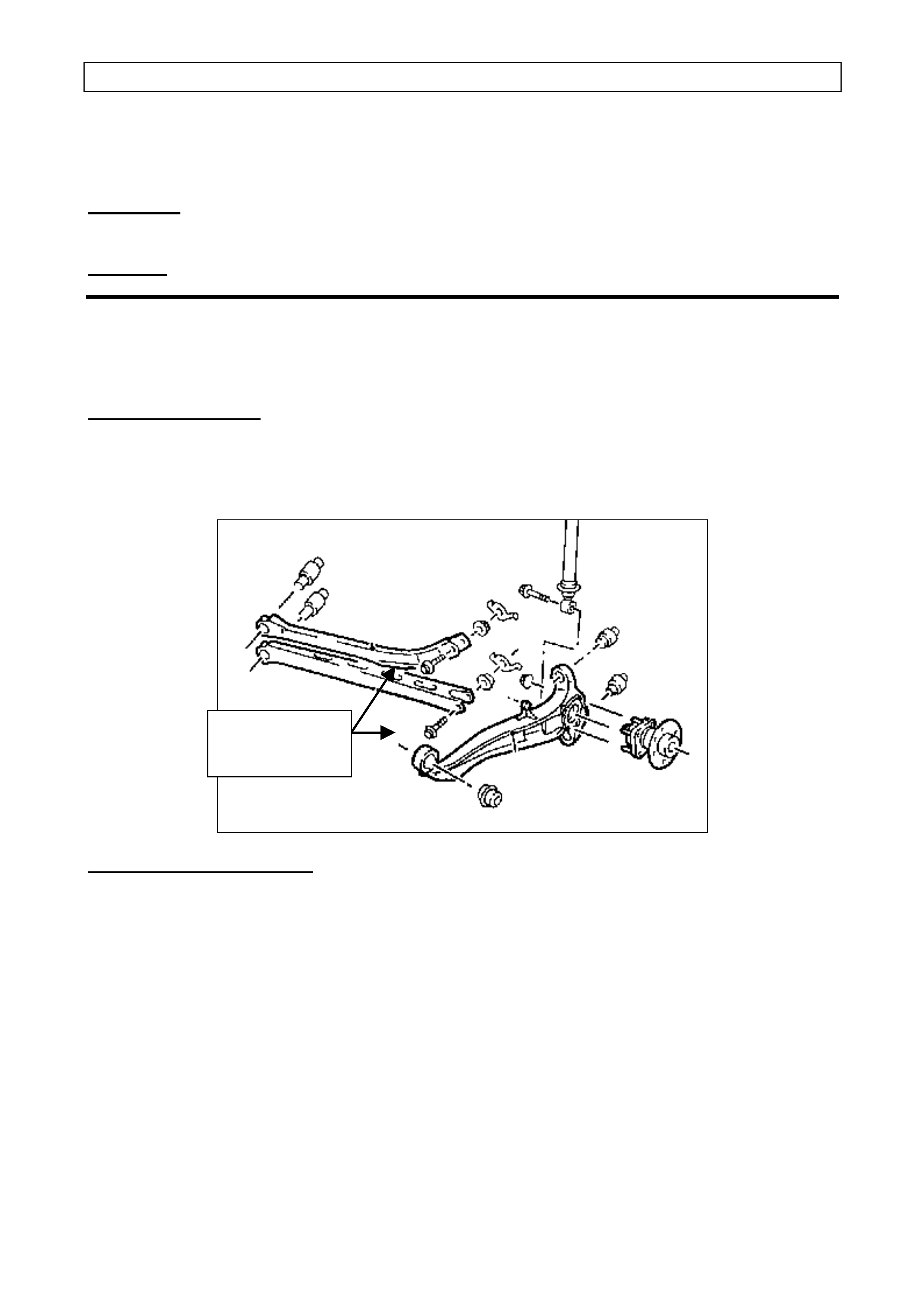
Torque Check
Bolts, LH & RH
Side of Vehicle

DEALERSHIP ACTION REQUIRED
Vehicles in Dealership Stock
Perform the necessary campaign action on any JS Series Vectra vehicle that falls within the VIN
range held in Dealership Stock. These vehicles must have this campaign action completed before
retail delivery of the vehicle or transfer to another dealership.
On Presentation of Any JS Series Vectra Vehicle
On presentation of any JS Series Vectra vehicle considered by the customer to be affected by this
action, or on presentation of a JS Series Vectra vehicle for any reason, confirm that the vehicle
falls within the affected VIN range. If the vehicle requires campaign action, refer to the Detailed
Technical Instructions included at the end of this bulletin.
In summary, the rear upper and lower control arm to rear suspension arm bolts (both sides) are to
be torque checked. If the bolts are not to the specified checking torque (90Nm), the upper and
lower control arms should be inspected and replaced where necessary.
Apply a Campaign Completed identification label to the right hand front ‘A’ pillar and submit a
warranty claim using the information provided.
Vehicle Identification
All campaigned vehicles must have a Campaign Completed identification label applied to the right
hand front ‘A’ pillar, between the hinges, with details of the campaign, 99-H-01, dealership code
and date completed, legibly entered on the label with a permanent ink pen.
Extra campaign identification labels are available free of charge from:
Moore Business Systems
Facsimile: (03) 9270 8900
Attention: Mr. Bob Curry
Quote stock No. SD 28156, on a Moore Business Systems ‘packaged goods’ order form (or
facsimile if not available) for a box of 100 labels.
Vehicle Listings
Listings of affected vehicles shown in our customer name and address files are included with this
bulletin. Should dealers have any information to update the supplied listings, please update listing
and fax to:
Holden Ltd
Att: D. McMurray
Warranty Administration
Facsimile: (03) 9647 2525
Parts Information
No parts are required to complete this campaign action, except for in the unlikely event where a
vehicle has control arm damage. Parts when required can be ordered from HSPO. Refer to
PartFinderTM for specific service part numbers.

Owner Notification
Owners will be contacted directly by letter from Holden, providing details of the recall and
requesting them to arrange for the campaign action to be carried out together with the additional
field rework on applicable vehicles. Following is a draft of the cust om er letter.
Dear Holden Customer ,
At Holden we continually strive to enhance the ownership experience of our customers through
continuous product improvement, aftersales service and effective customer communication.
Holden’s foremost concern is the continued safety of our customers. Accordingly the recall
campaign described below is being under t aken as a safety precaut ion.
Holden has been alerted to the fact that within a determined production range of vehicles, the
specified torque settings may not have been achieved for attaching bolts incorporated in the rear
suspension system of your vehicle. In certain circu mstances, this may r esu lt i n poor and
unpredictable vehicle handling.
Holden has initiated this action as a precautionary measure to ensure the handling characteristics of
your vehicle are not compromised.
Our records show that your Holden Vect ra vehicle was manufact ured w ithin the det erm ined range. I t
is therefor e necessary for you to m ake a service booking w ith a H ol den dealership of your choice to
have the necessary wor k per f or m ed on your vehicle.
Some additional wor k may also be performed on your vehicle on presentation at the dealership. A
slight adjustment may be made to the routing of brake pipes located at the front of the vehicle.
This will ensure components are located correctly and prevent rubbing of the brake pipes which
may lead to paint r emoval and the potent ial f or corrosion.
All work will be carried out free of charge and can be completed while you wait, provided the
necessary arrangements have been made with the Holden dealer. The work required will take
approximately half an hour to complete.
We know that effective communication is vital to helping your understanding of the issues involved
and trust that this letter provides you with all the infor m ation you need. If you have any quest ions, t he
Holden Customer Assistance Line - 1 800 033349 would be pleased to assist.
Thank you for your at t ention to this matter. Please accept our apologies for any inconvenience that
may be caused by this action.
Yours Sincerely
I.J.MURRAY
Manager Customer Assistance

WARRANTY CLAIM INFORMATION
ON COMPLETION OF CAMPAIGN ACTION DEALERS MUST IMMEDIATELY SUBMIT A
WARRANTY CLAI M using the following data.
Description: Inspect Rear Suspensi on Control Arms
Labour Operat ion No: T980401
Standard T im e: 0.5 Hours
Failure Code: 96
Case Type: 08
In the event that components are replaced, use the appropriate labour operation number listed
below:
Description: Replace RH Lower Cont rol Arm (including inspect i on)
Labour Operat ion No: T980402
Standard T im e: 1.0 Hours
Failure Code: 96
Case Type: 08
Description: Replace LH Lower Cont rol Arm (including inspection)
Labour Operat ion No: T980403
Standard T im e: 1.0 Hours
Failure Code: 96
Case Type: 08
Description: Replace RH Upper Control Arm (including i nspection)
Labour Operat ion No: T980404
Standard T im e: 0.8 Hours
Failure Code: 96
Case Type: 08
Description: Replace LH Upper Control Arm (including i nspect i on)
Labour Operat ion No: T980405
Standard T im e: 0.8 Hours
Failure Code: 96
Case Type: 08
The range of vehicles has been identified using t he VIN number. Please ensure all vehicle details
are included when submitting warrant y claim informat ion as per t he normal warranty processes.
War ranty claim submission is used to updat e our r ecord of cam paign completion and determines
whether furt her cust omer contact is necessar y to act ion all af fected vehicles. Please ensur e on
completion of the campaig n action that a warranty claim is submitted prompt ly. I n the event that
parts ar e r eplaced, REPAC will request ret ur n of all replaced par t s via the REPAC r epor t .
DETAILED TECHNICAL INSTRUCTIONS CAMPAIGN 99-H-01
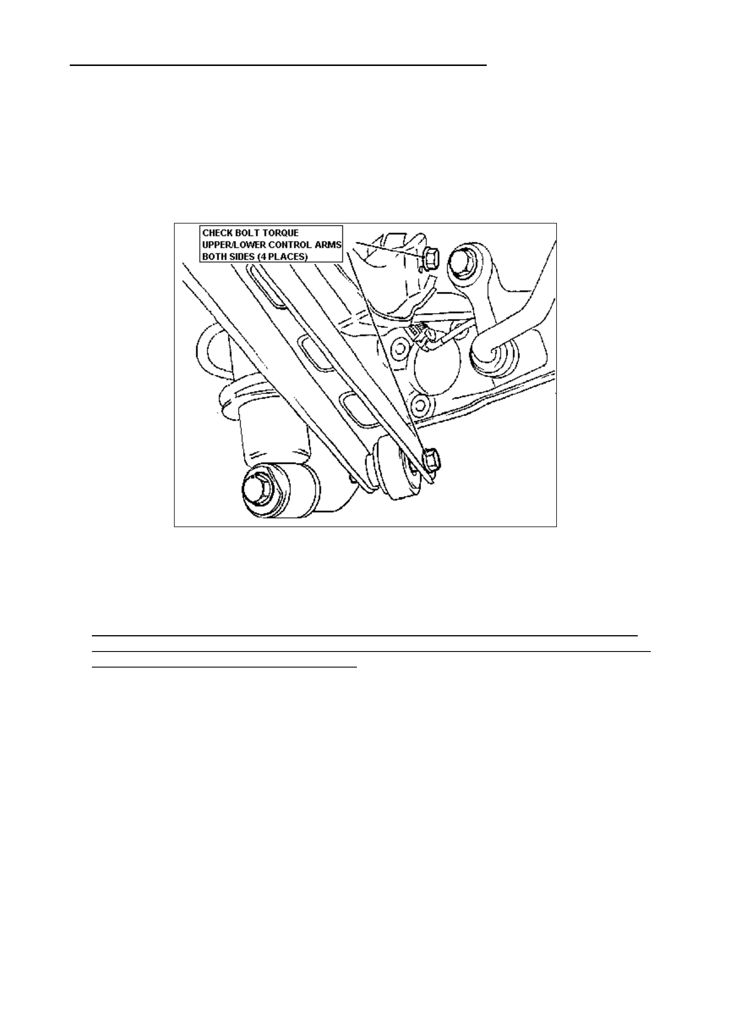
STEP 1: Raise the vehicle on a hoist and locate the upper and lower contr o l ar m bolts as
indicated in the figure below.
STEP 2: Using a tor que wrench set to 90 Nm, check t he t or que of all four ( 4) upper and
lower control arm t o r ear suspension arm bolts on bot h r ight-hand and left-hand sides of the
vehicle. The torque specif ied, 90 Nm, is the checking tor que req uir ed for t his cam paign action.
Refer t o TIS if the specific torq ue settings and pr ocedur es ar e r e quired f or component
replacement (not necessary for the checking pr ocedur es).
STEP 3: If t he upper or lower control arm bolts are found to be excessively loose, disconnect
the respective arms and inspect. Replace the arm s , bolts and other parts where necessary only if
elongation of the holes or other damag e is evident. Ensur e that service procedures ar e followed
and use the appropriat e t orque sett ings in TIS.
Important: The control ar m to suspension link fastener s ar e single use bolts only. DO NO T
remove bolts unnecessarily. Only completely remove the nut and bolt if excessively loose and
inspection of t he control arm( s) is necessar y.

Attachment “A”
FIELD REWORK: Proximity of Brake Pipes to the Automatic Transmission
Input Speed Sensor
• Corrective action applies to all JS Ser ies Vect r a vehicles with AUTOMATIC TR ANSMI SSION
and ABS built from st ar t of pr oduction L314383 to L390426.
• Ensure the vehicle f alls within the above VIN range and is equipped with autom at ic
transmission and ABS. Warranty claims subm it ted outside this r ange and without the
necessary options will not be accepted.
INTRODUCTION: The purpose of the field rework is to ensur e t hat the 3 brake pipes that run out
of t he ABS m odulat or and down past the top of the automatic transmission clear t he speed sensor
by at least 10mm. Under vehicle accelerat ion or traversing over bumps, a rubbing condition m ay
occur if t her e is not at least 10 mm clearance.
A minimum clear ance of 10 mm is required.
PROCEDURE:
1. Determine ther e is at least 10 mm clear ance between the brake pipes and the speed sensor
as indicated in Figur e 1 ( next page). I f ther e is 10 m m or m ore clearance, no further r ework
action is req uir ed.
2. If t her e is less than 10 mm clearance, suppor t the brake pipes using a long edgeless object
such as a wooden hammer handle positioned as indicated in Figure 1.
3. Holding the ham m er , grasp the br ake pipes near the speed sensor and with an upward and
outward gentle m ovement t owards the passenger side, slightly bend the brak e pipes to
achieve at least 10 mm clear ance. DO NOT excessively bend the pipes.
Only 10 – 15 mm clearance is required. Too much force can result in excessive clearance and
damage t o t he br ake pipes. In som e instances, it may be necessary to bend the brake pipes
individually.
4. Once the corr ect clear ance has been obtained, ensure the pipes ar e evenly spaced and
correctly engaged in the spacer br acket. The spacer brack et should be positioned as close as
possible to the bend in the br ake pipes as possible.
All vehicles requiring this r ew o r k are subject to t he ( 99- H- 01) campaign action. The vehicle
Campaign Com pleted identification label used to ident ify campaign 99-H-01 action (SD 28156)
should be used as an identif icat ion to record completion of t he above rework action. Place a “B”
on the label if t he rework has been performed.
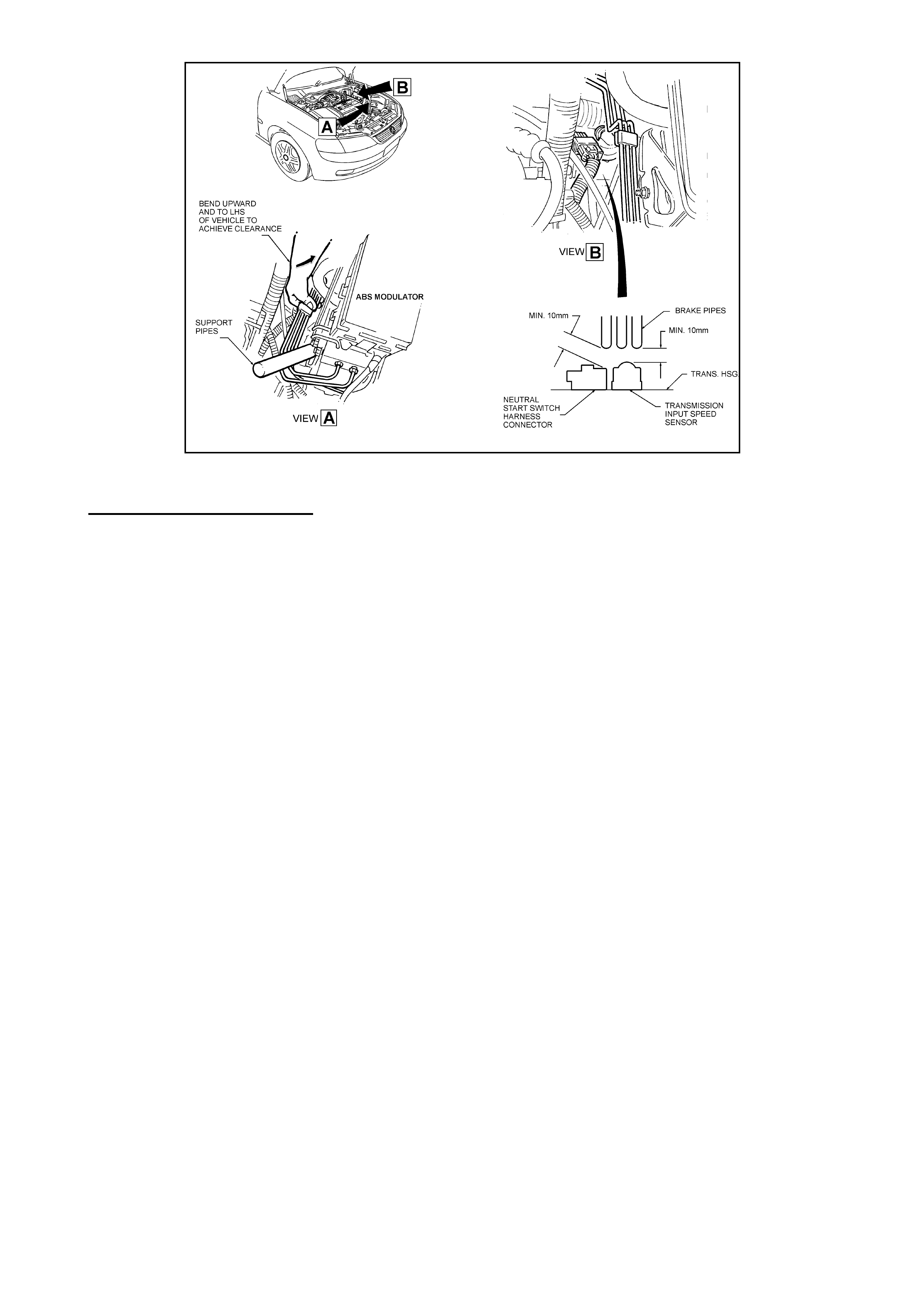
FIGURE 1
Warranty Claim Information
Use the f ollowing informa t ion for warrant y claims:
Description : Position Brak e Pipes for Clear ance
Time : 0.3 hr
Labour Op.No. : H000213
Failure Code : 95
SUBMITTING W ARRANTY CLAIMS:
Dealers are rem inded that warranty claim submission is used to updat e our r ecor d of campaign
and rework complet ion. Please ensur e on com pletion of t he r equired action that a warranty claim
is promptly submit t ed and the replaced parts ar e r etained for return to REPAC when requested.

PRODUCT CAMPA IGN BULLETIN
99-H-02
March 1st , 1999
SUBJECT : PROTECTION OF WIRING HARNESS TO SEAT LIFTER MOTORS
MODEL : 1997 VT SERIES VEHICLES
This bulletin is t o advise Holden Dealerships of the init iation of a saf ety relat ed campaign on some
1997 VT Series vehicles. The wiring harness to some drivers’ (all models) and passengers’
(Calais model only) seat lifter m ot or s is t o be inspected and where necessary replaced.
Description of Def ect
Investigations have identified a batch of seats that were assembled with unprotected wiring which
is routed between the motor bracket and mat supporting the seat cushion. Under extreme
pressure, t he seat cushion may deflect enoug h to crush t he wiring harness and expose bare wires
to the motor bracket resulting in a short circuit. As a result, sufficient heat may be generated to
cause the wiring insulation at the seat to burn, however the likelihood of this happening is
extremely low.
Details of Affected Vehicles
Vehicles requiring this campaign action ar e some 1997 built VT Ser ies vehicles built f rom 24/ 06/97
to 15/08/97 inclusive.
VIN numbers L246596 to L259927 inclusive, sets the range of vehicles affected.
3691 vehicles require inspection.
Dealership Action Requi red
On presentat ion of any vehicle considered by the customer to be aff ected by this campaign, or on
presentation of a 1997 VT Series vehicle for any reason, confirm that the vehicle falls within the
affected range. Refer to the Detailed Instructions included with this bulletin (Attachment “A”) for
campaign act ion.
In summary, the wiring harness to the seat motors is to be inspected for presence of a PVC
sleeve. If the sleeve is not installed, replace t he seat harness.
Vehicle Ident ification
All campaigned vehicles must have a completed campaign identification label applied to the right
hand front ‘A’ pillar, between the hinges, with details of the campaign, 99-H-02, dealership code
and date completed, legibly entered on the label with a permanent ink pen.
Extra campaign ident ification labels ar e available free of charge from :
Moore Business Systems
Facsimile: (03) 9270 8900
Attention: Mr. Bob Curry
Quote stock No. SD 28156, on a Moore Business Systems ‘packaged goods’ order form (or
facsim ile if not available) for a box of 100 labels.

Vehicle List ings
Listings of affect ed vehicles shown in our customer nam e and addr ess files are included with this
bulletin. Should dealers have any infor m at ion to update the supplied list ings, please update listing
and fax to:
Holden Limited
Att: P. STARICK
War ranty Administration
Facsimile: (03) 9647 2525
Parts Information
Holden expects that less than 20% of the vehicles inspected will require harness replacement.
Each dealership will receive as an initial quantity of one 8VK/8VL harness and a set of tie straps
(Item 1 and 3 from below) free of charge. Use the Attached Material Order form to order
additional parts from Salmat.
Consume stock from the initial quant ity supplied and then only order replacement har nesses in line
with customer bookings.
Note: When making a booking for a VT Calais, imm ediat ely order I tem 2 and 3 f rom below in case
replacement is r equired. I f not r equired, hold in st ock f or possible fut u r e needs.
Item Part No. Description Qty/seat
1 Holden
92142707 • Right Hand 4- way seat lif t e r
harness f or dr iver seat.
8VK and 8VL models
1
2 Holden
92142714 • Right Hand 8 way seat lifter
harness f or dr iver seat
8VX models only
1
Holden
92142715 • Left Hand 8 way seat lif ter
harness passenger seat
8VX models only
1
3 92138137 • Tie straps 2

Owner Notification
Owners will be contacted directly by letter from Holden, providing details of the safety related
campaign and req uesting them to arrange f or the seat harness inspection and rectification by any
Holden dealership. T he t ext of the let ter is as follows:
Dear Holden Customer ,
At Holden we continually strive to enhance the ownership experience of our customers through
continuous product improvement, industry leading afters ales service and clear and concise cust omer
communication.
Holden’s foremost concern is the continued safety of our customers and the recall campaign
described below is being undert aken as a necessar y saf et y pr ecaut ion.
Holden has identified a small number of vehicles where the wiring to the seat lifter motors
(beneath the seat), was assembled without added protection. This may result in damage to the
wiring from the seat frame which in extreme cases may cause an electrical short circuit. As a
result, sufficient heat may be generated to cause the w iring insulation at the seat to burn, how ever
the likelihood of this happening is extremely low .
Holden has initiated a recall to inspect the harness of potentially affected vehicles. This action is
necessary to ensure that the harness is protected and free of damage.
Should an inspection reveal that the seat harness is not adequately protected a replacement seat
harness will be fitted. This action is a precautionary measure to ensure the seat operat es effectively
for the longer term.
Our records show that your Holden vehicle was manufactured within the affected range. It is
therefore necessary for you to make a service booking with a Holden dealership of your choice to
have the necessary inspection and serv ice per f or med.
This work will be carried out free of charge and can be completed while you wait, provided the
necessary arrangements have been made with your Holden dealer. If corrective action is
necessary, the work requir ed will take approximately 1 hour to complete.
We know that effective communication is vital to helping your understanding of the issues involved
and trust that this letter provides you with all the information you need. If you should have any
questions, the Customer Assistance Line - 1 800 033349, would be pleased to assist.
Thank you for your attention in this matter. Please accept our apologies for any inconvenience
which may be caused by this act ion.
Yours Sincerely
I.J.MURRAY
Manager Customer Assistance

WARRANTY CLAIM INFORMATION
ON COMPLETION OF CAMPAIGN ACTION DEALERS MUST IMMEDIATELY SUBMIT A
WARRANTY CLAI M using the following data.
Use ONE of the following Labour Operat ion Num bers for this campaign.
1. If inspect ing one or both seats:
Description: Inspect seat harness f or sl eeve fitment.
Labour Operat ion No: T980801
Standard T im e: 0.4 Hours
Failure Code: 96
Case Type: 08
2. If t he dr iver seat har ness needs r eplacing:
Description: Inspect and Replace Driver seat harness.
Labour Operat ion No: T980802
Standard T im e: 0.8 Hours
Failure Code: 96
Case Type: 08
3. If t he passenger seat har ness needs r eplacing (Calais only):
Description: Inspect and Replace Passenger seat harness.
Labour Operat ion No: T980803
Standard T im e: 0.8 Hours
Failure Code: 96
Case Type: 08
4. If bot h seat harnesses need replacing ( Calais only):
Description: Inspect and Replace both seat harnesses.
Labour Operat ion No: T980804
Standard T im e: 1.2 Hours
Failure Code: 96
Case Type: 08
The range of vehicles has been identified using t he VIN number. Please ensure all vehicle details
are included when submitting warrant y claim information as per the norm al warrant y procedur es.
War ranty claim submission is used to updat e our r ecor d of complet ion and det er m ines whether
further customer cont act is necessar y to act ion all af fected vehicles. Please ensur e on com plet ion
of t he cam paign action that a warrant y claim is subm it ted promptly.
REPAC will request re t urn of all replaced parts via the REPAC r eport.
DETAILED TECHNICAL INSTRUCTIONS CAM PAIGN 99-H- 02
The flow chart below provides an overview of the rectification required for campaign 99-H-02.
Dealers should follow this when diagnosing affected vehicles. The procedures referred to in the
flow chart are explained further individually.
Dealers should check that the vehicle falls within the affected range before performing campaign
action.
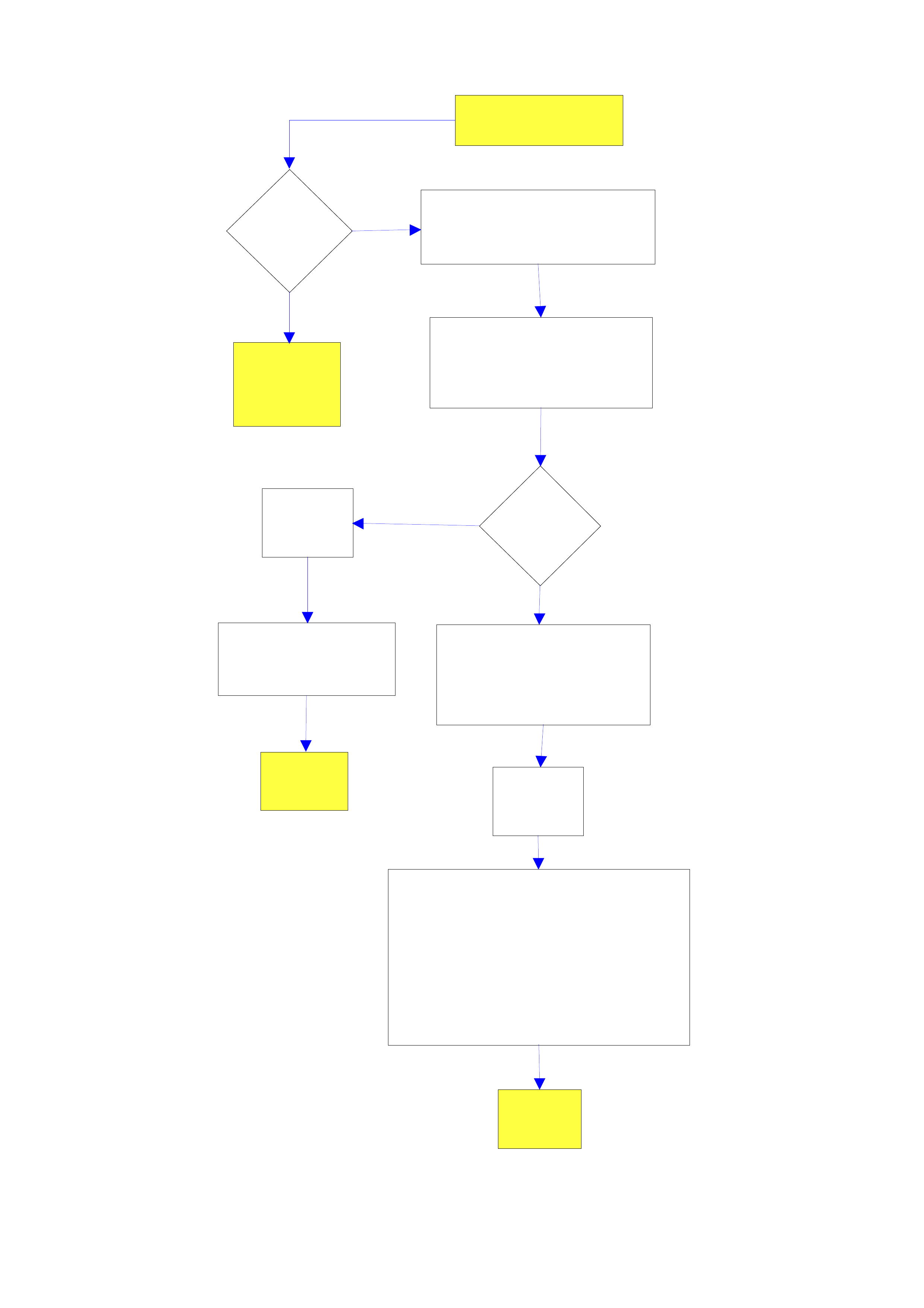
START
Is PVC
sleeve
fitted ? R ef
to Fig 1
Replace seat harness. Ref to
Fig 2 View A for revised
routing path -Fi g 2 View B for
Calais. Follow Procedure B.
I ns pect seat har ness. Include
passenger seat for Calais.
Refer t o Proc edure A ..
Apply
Campaign
Label
Submit warranty claim
using LOp T980801.
END
Submit warranty claim using appropriate
Labour Operation number.
If drivers seat harness was only replaced,
use LOp T980802.
I f passenger se at harnes s was only
replaced used LOp T980803.
If both seat harnesses were replaced use
LOp T980804.
Apply
Campaign
Label
END
Is PSN b/w
L246596 and
L259927 incl?
A rr ange vehic l e booking and
order parts. Allow 3 days for
parts delivery.
Not involved
in Campaign
99-H-02.
Yes
No
Yes
No
Attachment A
Procedures:
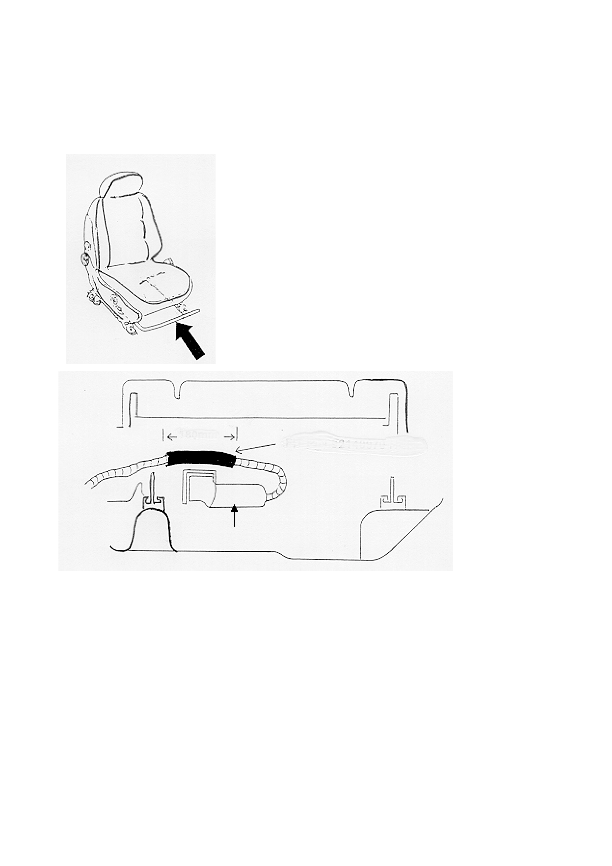
A) Check the harness for the fitment of PVC t ube.
• Position the seat fully rearward and adjust t he whole seat upward to its m aximum height
• Locate, under the seat, the harness for the seat lif ter mot or (this harness runs acr oss the top of
the seat lifter m ot or mounting bracket - ref er Figure1.)
180 mm Check for fitment of
this sleeve
Seat lifter motors
Figure 1
• If there is an existing PVC sleeve over the harness no further campaign action required,
otherwise, replace the harness- ref er to Procedure B.
B) Replace the harness for the seat lifter motor- Also applicable to passenger seat (Calais
only)
• Remove the fuse F26 for t he SRS system - this will prevent a code logging .
• Remove the driver’s seat from the vehicle (refer to 2.1 FRONT BUCKET SEAT ASSEMBLY of
the VT Ser ies I Ser vice Information)
• Remove the harness f or the seat lif ter motor. Note: mar k on the seat the position of the t wo tie
straps retaining the harness pr ior t o removing the tie str aps.
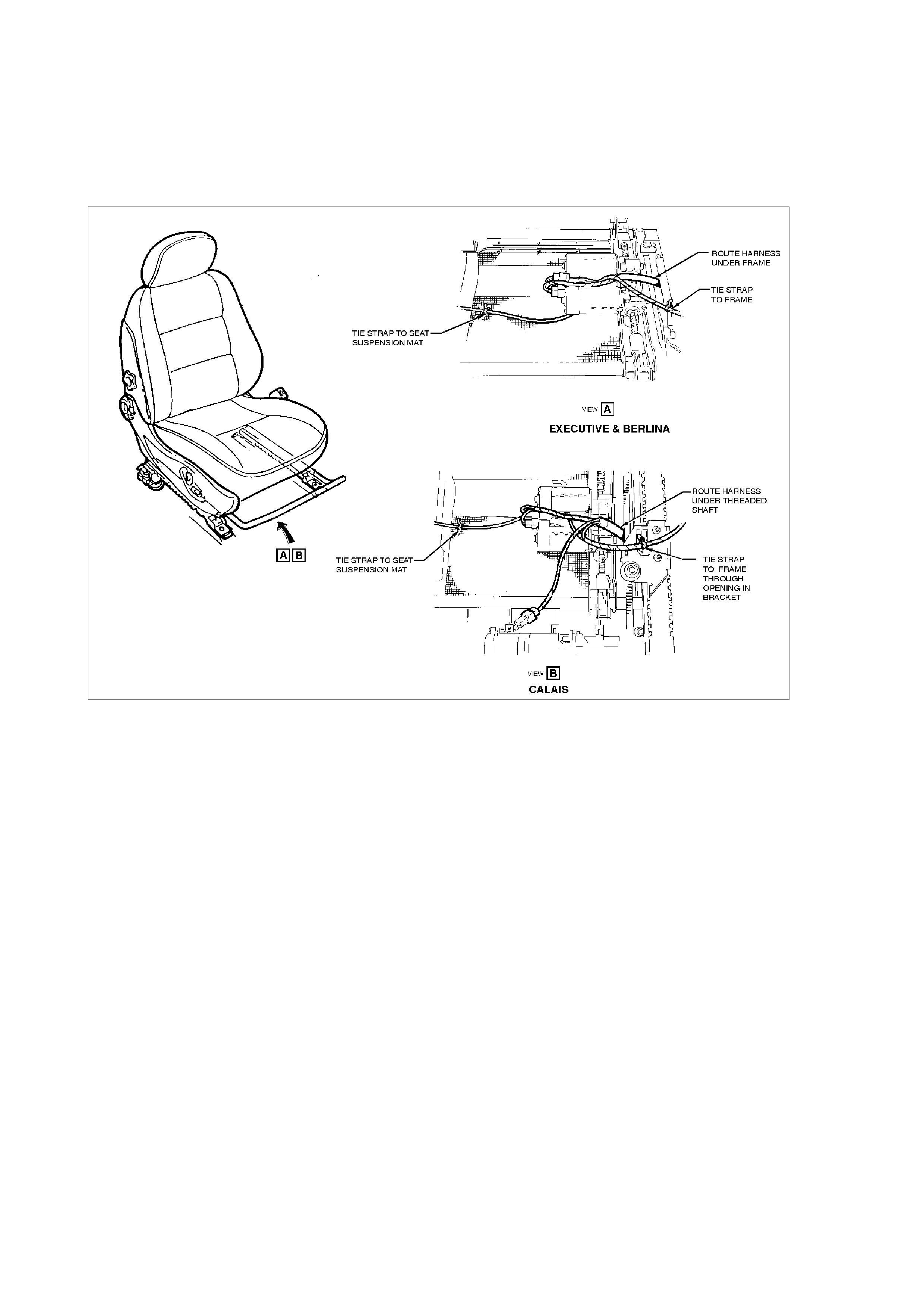
• Fit the new harness for the seat lifter motor. Refer Fig 2 View A.
• For Calais: Harness is to be routed between the threaded shaft (lead screw) and motor
mounting bracket. Refer to Fig 2 View B. Retain the harness with tie straps in the positions
previous marked. Red tape identifies the point s on t he har ness which are to be r etained.
• Plug in the connectors for the seat lif ter motors (white and black connectors). If f itting harness
to a Calais model connect t o the horizontal slide motor (red). Refer t o Fig 2 View B.
• Install the pr et ensioner connector clip.
• Reinstall the seat to the vehicle (refer to 2.1 FRONT BUCKET SEAT ASSEMBLY of the VT
Series I Service Information)
• Reinstall fuse F26 for t he SRS system
• Check seat elect r ical functions for corr ect oper ation
• Apply Campaign completed label
• Submit warranty claim
Figure 2
Attachment to Campaign Bulletin (Following)

SALMAT
MATERIAL ORDER FORM
Holden VT Series
Seat Harness and Tie Strap
Fax No.: (03)-9251-6352
Attention: N. Kennedy
This dealership wishes to order additional Seat Harness/s and Tie Straps for completion of
recall Campaign 99-H-02.
Please dispatch the parts detailed below, to this dealership, as soon as possible.
__________________________________________________________________________
Item Part Number Amount
1 92142707 (Drivers seat -RH 4 way
8VK and 8VL models)
2 92142714 (Drivers seat -RH 8 way
8VX models)
92142715 (Passengers seat - LH 8
way 8VX models)
3 92138137 in packs of 5
___________________________________________________________________________
From Dealer Code: ___________ Date:_____________________
Dealership Name: ______________________________________
Dealership Service Manager: _____________________________________
(please PRINT your name)
Fax This Form To : SALMAT (03)-9251-6352

PRODUCT CAMPAIGN BULLETIN
99-H-03
April 21, 1999
SUBJECT : JS VECTRA CHILD RESTRAINT ANCHORAGES
MODEL : JS SERIES VECTRA (IMPORT, HATCH ONLY)
This bulletin is t o advise Holden Dealerships of the init iat ion of a saf et y r elated campaign t o rework
the rear child r est r aint anchorage br ackets on JS Series Vect r a ( hatch only) vehicles.
Description of Def ect
Insuf ficient weld penetration of the spot weld that at taches the child anchorag e br acket to the rear
panel.
Details of Affected Vehicles
Vehicles requir ing this campaign action are impor ted JS Series Vectra ( hatch ONLY) vehicles.
A list of all affected vehicles, ‘Attachment A’, is included with this bulletin. The broad range of
affected vehicles falls within the tag range Y067450 to Y076366 (build date as per the Australian
Compliance Plate, August 1998 to February 1999). Dealers must verify that the vehicle to be
reworked is on the affected vehicle listing provided with this bulletin.
267 vehicles within the above rang e are involved.
DEALERSHIP ACTION REQUIRED
Vehicles in Dealership Stock
Perform the necessary campaign action on any JS Series Vectra (hatch) vehicle that falls within
the Tag number range held in Dealership Stock. These vehicles must have this campaign action
completed before ret ail delivery of the vehicle or transfer to anot her dealership.
On Presentati on of Any JS Series Vectra Vehicle
On presentation of any JS Series Vectr a vehicle considered by the customer to be af f ected by this
action, or on presentation of a JS Series Vectra vehicle for any reason, confirm that the vehicle
falls within the broad affected Tag number range. If the vehicle falls within the broad affected tag
range and is on the affected vehicle listing (Attachment A) provided with this bulletin, rework the
vehicle.
If the vehicle requires campaig n action, ref er to the Detailed T echnical Instructions included at the
end of t his bulletin.
In summary, the three child anchorage brackets located behind the rear inner panel trim and rear
bumper facia, are to be reworked by drilling 2 holes in each anchorage (3 anchorage’s, 6 holes in
total) and fastening with a screw and nut assembly.
Apply a Campaign Completed identification label to the right hand front ‘A’ pillar and submit a
warranty claim using t he inform at ion pr ovided.

Vehicle Ident ification
All campaigned vehicles must have a Campaign Completed identif ication label applied to the rig ht
hand front ‘A’ pillar, between the hinges, with details of the campaign, 99-H-03, dealership code
and date completed, legibly entered on the label with a permanent ink pen.
Extra campaign ident ification labels ar e available free of charge from :
Moore Business Systems
Facsimile: (03) 9270 8900
Attention: Mr. Bob Curry
Quote stock No. SD 28156, on a Moore Business Systems ‘packaged goods’ order form (or
facsim ile if not available) for a box of 100 labels.
Vehicle List ings
Two listings are included with this bullet in:
1. A summarised list ing of all vehicles affe ct ed by this cam paign action (Attachment ‘A’) .
2. Listing of af fected vehicles shown in our customer nam e and addr ess files.
Should dealers have any informat ion t o updat e the supplied listings, please updat e listing and fax
to:
Holden Ltd
Att: P. Starick
War ranty Administration
Facsimile: (03) 9647 2525
Parts Information
Parts required to complete this campaign action are tabulated below. Parts are available from
HSPO.
Part No.: Description: Qty
Req’d:
92138175 (SP3836) SCREW 6
11094423 NUT 6
11035613 WASHER 6

Owner Notification
Owners will be contacted directly by letter from Holden, providing details of the recall and
requesting them to arrange for the campaign action to be carried out. Following is a draft of the
customer letter.
Dear Holden Customer ,
At Holden we continually strive to enhance the ownership experience of our customers through
continuous product improvement, aftersales service and effective customer communication.
Holden’s foremost concern is the continued safety of our customers. Accordingly the recall
campaign described below is being under t aken as a safety precaut ion.
Holden has been alerted to the fact that within a determined production range of vehicles, the spot
weld that secures the rear child seat anchorage brackets to the rear panel may not have had
sufficient penetration causing possible weaknesses in the restraint anchorage system.
To improve the st r ength of the anchorage system, your Holden dealer will modif y t he anchorage
by fitting additional f ast ener s.
Holden has initiated this action as a precautionary measure to ensure the anchorage brackets are
sufficiently secured and that the safety of all passengers is not compromised.
Our records show that your Holden Vect ra vehicle was manufact ured w ithin the det erm ined range. I t
is therefor e necessary for you to m ake a service booking w ith a H ol den dealership of your choice to
have the necessary wor k per f or m ed on your vehicle.
All work will be carried out free of charge and can be completed while you wait, provided the
necessary prior arrangements have been made with your Holden dealer. The work required will
take approximat ely one hour to complete.
We know that effective communication is vital to helping your understanding of the issues involved
and trust that this letter provides you with all the infor m ation you need. If you have any quest ions, t he
Holden Customer Assistance Line - 1 800 033349 would be pleased to assist.
Thank you for your at t ention to this matter. Please accept our apologies for any inconvenience that
may be caused by this action.
Yours Sincerely
D.McMurray
Manager Customer Assistance
WARRANTY CLAIM INFORMATION
ON COMPLETION OF CAMPAIGN ACTION DEALERS MUST IMMEDIATELY SUBMIT A
WARRANTY CLAI M using the following data.
Description: Rework Child Restraint Anchorage on Hat c h Models
Labour Operat ion No: T980901
Standard T im e: 1.1 Hours
Failure Code: 96
Case Type: 08
The range of vehicles has been identified using the Tag number. Please ensure all vehicle details
are included when submitting warrant y claim informat ion as per t he normal warranty processes.
War ranty claim submission is used to updat e our r ecord of cam paign completion and determines
whether furt her cust omer contact is necessar y to act ion all af fected vehicles. Please ensur e on
completion of the campaig n action that a warranty claim is subm it t ed promptly.
DETAILED TECHNICAL INSTRUCTIONS CAMPAIGN 99-H-03
1. Remove rear bumper facia as per t he ser vice instructions.
2. Remove the inner tr im panel t hat covers the child rest r aint anchors.
3. Place a piece of cardboard or dropsheet i n t he hat ch t o cat ch any swarf from the
drilling operation.
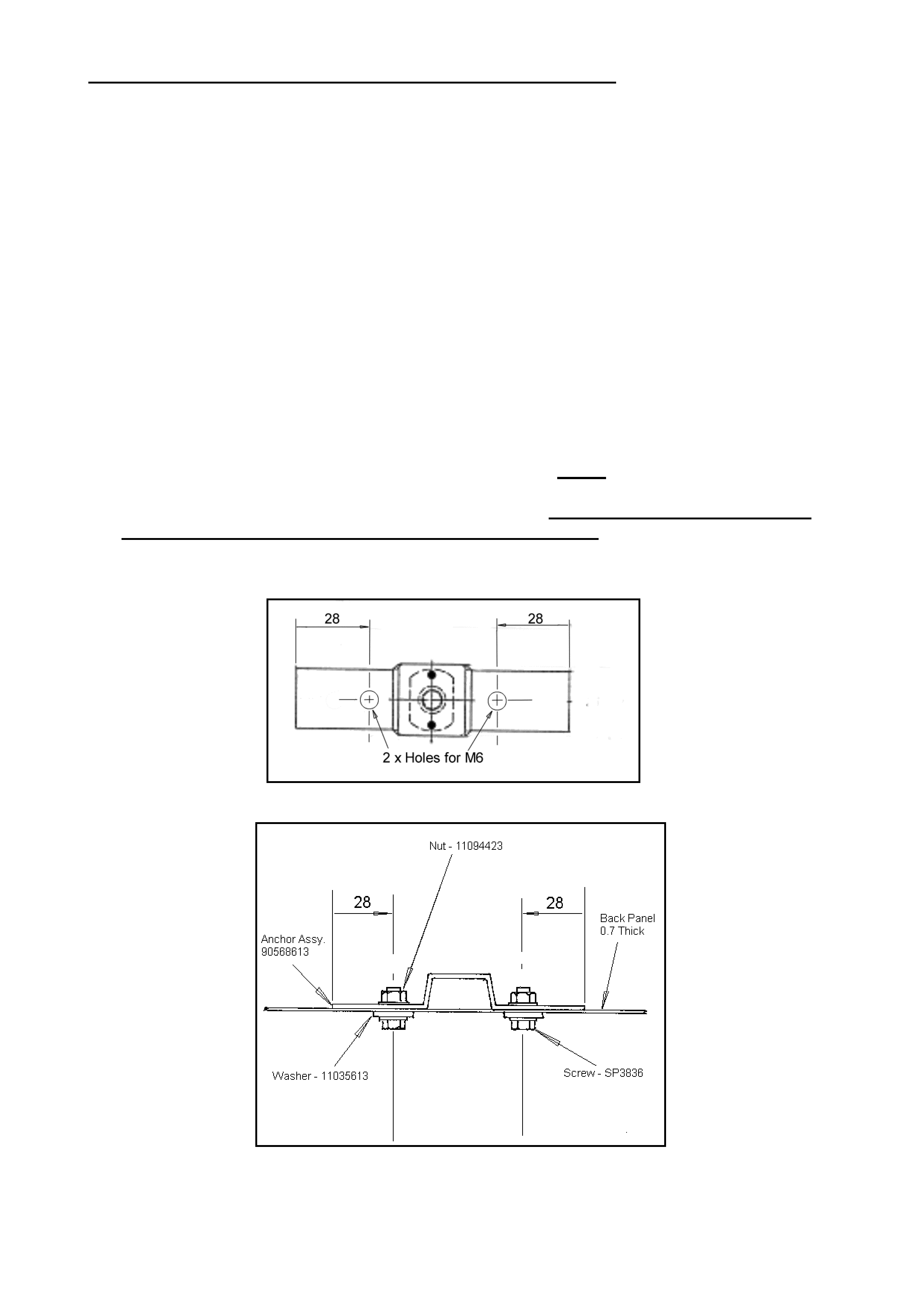
4. As per Figur e 1& 2 below, drill 6. 0m m diameter holes for M6 screw’s with centres 28 mm from
the outer end of the 3 anchor s as shown. Mark, centre punch and drill carefully throug h the
anchor assembly and the back panel from inside t he hatch.
5. Apply a bead of silicon sealer (92140051) ar ound the head of each scr ew, under t he nut
flang e and on t he outer panel surface under the scr ew head.
6. Place 18mm washers (11035613) onto t he scr ews.
7. Insert scr ews (92138175) int o each hole with head outboard.
8. Place nuts (11094423) ont o each scr ew and torque each screw to 12Nm.
9. Ensure all 3 anchors are secur ed and t or qued correct ly. Ensure al l swarf is cleaned from
the inside of t he vehicle, including in the spare wheel wel l.
10. Refit the inner trim panel and rear bumper facia assembly.
Figure 1: View f rom within hatch looking rearward.
Figure 2
92138175

Page 1 99-H-03
TAG #
ISOVIN #
W/SALE D/C
TAG #
ISOVIN #
W/SALE D/C
Y067450 W0L0JBF68W7137415 269 Y072635 W0L0JBF68W7156553 415
Y067451 W0L0JBF68W7137499 603 Y072636 W0L0JBF68W7156864 300
Y067452 W0L0JBF68W7137583 603 Y072637 W0L0JBF68W7156892 706
Y067453 W0L0JBF68W7137680 406 Y072638 W0L0JBF68W7159262 706
Y067454 W0L0JBF68W7138217 124 Y072640 W0L0JBF68W7159424 434
Y067456 W0L0JBF68W7138374 452 Y072641 W0L0JBF68W7159520 280
Y067457 W0L0JBF68W7138480 438 Y072642 W0L0JBF68W7159557 376
Y071345 W0L0JBF68W7156689 385 Y072643 W0L0JBF68W7159847 126
Y071346 W0L0JBF68W7156209 435 Y072644 W0L0JBF68W7159898 107
Y071347 W0L0JBF68W7156301 862 Y072645 W0L0JBF68W7159922 437
Y071348 W0L0JBF68W7156423 724 Y072646 W0L0JBF68W7159946 865
Y071349 W0L0JBF68W7156493 888 Y072647 W0L0JBF68W7159959 562
Y071350 W0L0JBF68W7156738 367 Y072648 W0L0JBF68W7161874 630
Y071441 W0L0JBF68W7156096 455 Y072649 W0L0JBF68W7162069 300
Y071442 W0L0JBF68W7156381 700 Y072650 W0L0JBF68W7162087 368
Y071443 W0L0JBF68W7157017 502 Y072651 W0L0JBF68W7162524 166
Y071550 W0L0JBF68W7155735 107 Y072750 W0L0JBF68W7156545 663
Y071551 W0L0JBF68W7155843 502 Y072751 W0L0JBF68W7156772 452
Y071552 W0L0JBF68W7156534 603 Y072752 W0L0JBF68W7156811 353
Y071553 W0L0JBF68W7156731 374 Y072753 W0L0JBF68W7159906 764
Y071589 W0L0JBF68W7156246 368 Y072754 W0L0JBF68W7161935 706
Y071591 W0L0JBF68W7156278 445 Y072755 W0L0JBF68W7161941 422
Y071592 W0L0JBF68W7156316 435 Y072756 W0L0JBF68W7162203 895
Y071593 W0L0JBF68W7156564 502 Y072757 W0L0JBF68W7162305 610
Y071594 W0L0JBF68W7156783 512 Y072758 W0L0JBF68W7162487 300
Y071595 W0L0JBF68W7156836 659 Y072759 W0L0JBF68W7162576 412
Y071638 W0L0JBF68W7156411 616 Y072760 W0L0JBF68W7162759 369
Y071639 W0L0JBF68W7156463 434 Y072761 W0L0JBF68W7162788 124
Y071640 W0L0JBF68W7156583 343 Y072762 W0L0JBF68W7162839 376
Y071725 W0L0JBF68W7156204 773 Y072763 W0L0JBF68W7162849 526
Y071726 W0L0JBF68W7156221 434 Y072764 W0L0JBF68W7162913 126
Y071727 W0L0JBF68W7156263 858 Y072765 W0L0JBF68W7163121 520
Y071728 W0L0JBF68W7156401 300 Y072766 W0L0JBF68W7163131 124
Y071729 W0L0JBF68W7156724 822 Y072767 W0L0JBF68W7163136 727
Y071730 W0L0JBF68W7156905 435 Y072768 W0L0JBF68W7163163 888
Y071731 W0L0JBF68W7157251 800 Y072769 W0L0JBF68W7163168 124
Y071732 W0L0JBF68W7157315 603 Y072770 W0L0JBF68W7163363 502
Y071733 W0L0JBF68W7157661 616 Y072771 W0L0JBF68W7163806 343
Y071734 W0L0JBF68W7158564 502 Y072772 W0L0JBF68W7164368 437
Y071735 W0L0JBF68W7158604 455 Y072925 W0L0JBF68W7156637 631
Y071796 W0L0JBF68W7156526 313 Y072926 W0L0JBF68W7162347 381
Y071798 W0L0JBF68W7157074 342 Y072927 W0L0JBF68W7162424 141
Y071799 W0L0JBF68W7159182 438 Y072928 W0L0JBF68W7162621 502
Y071800 W0L0JBF68W7159569 612 Y072929 W0L0JBF68W7164130 163
Y072632 W0L0JBF68W7156329 435 Y072930 W0L0JBF68W7164260 700
Y072633 W0L0JBF68W7156416 362 Y072931 W0L0JBF68W7164592 455
Y072634
W0L0JBF68W7156451
605
Y072932
W0L0JBF68W7164762
616
ATTACHMENT 'A'
99-H-03 - AFFECTED VEHICLE LISTING

Page 2 99-H-03
TAG #
ISOVIN #
W/SALE D/C
TAG #
ISOVIN #
W/SALE D/C
Y072933 W0L0JBF68W7164961 107 Y073413 W0L0JBF68W7170409 581
Y072948 W0L0JBF68W7162326 484 Y073570 W0L0JBF68W7164374 141
Y072949 W0L0JBF68W7162782 124 Y073571 W0L0JBF68W7167016 422
Y072950 W0L0JBF68W7164292 166 Y073572 W0L0JBF68W7170422 376
Y072951 W0L0JBF68W7165250 435 Y073573 W0L0JBF68W7170851 338
Y072995 W0L0JBF68W7162678 381 Y073574 W0L0JBF68W7171807 141
Y072996 W0L0JBF68W7163092 603 Y073617 W0L0JBF68W7170320 802
Y072997 W0L0JBF68W7163357 166 Y073618 W0L0JBF68W7170649 415
Y072998 W0L0JBF68W7164239 739 Y073620 W0L0JBF68W7170900 706
Y072999 W0L0JBF68W7164280 636 Y073622 W0L0JBF68W7171505 413
Y073000 W0L0JBF68W7164917 706 Y073623 W0L0JBF68W7171594 547
Y073174 W0L0JBF68W7161862 376 Y073638 W0L0JBF68W7162156 565
Y073175 W0L0JBF68W7162529 373 Y073640 W0L0JBF68W7170185 252
Y073176 W0L0JBF68W7162668 610 Y073641 W0L0JBF68W7170719 616
Y073177 W0L0JBF68W7163313 486 Y073642 W0L0JBF68W7171464 124
Y073178 W0L0JBF68W7164286 603 Y073643 W0L0JBF68W7171599 434
Y073179 W0L0JBF68W7165188 124 Y073644 W0L0JBF68W7171675 564
Y073180 W0L0JBF68W7165302 320 Y073645 W0L0JBF68W7171820 894
Y073181 W0L0JBF68W7165344 124 Y073646 W0L0JBF68W7171849 166
Y073183 W0L0JBF68W7166889 512 Y073647 W0L0JBF68W7171887 129
Y073184 W0L0JBF68W7166942 636 Y073648 W0L0JBF68W7171947 434
Y073185 W0L0JBF68W7167000 50 Y073649 W0L0JBF68W7171983 339
Y073186 W0L0JBF68W7167155 368 Y073650 W0L0JBF68W7172472 434
Y073187 W0L0JBF68W7167222 354 Y073651 W0L0JBF68W7172703 461
Y073188 W0L0JBF68W7167228 438 Y073680 W0L0JBF68W7162534 895
Y073189 W0L0JBF68W7167239 438 Y073681 W0L0JBF68W7163156 413
Y073190 W0L0JBF68W7167495 502 Y073682 W0L0JBF68W7164865 437
Y073191 W0L0JBF68W7167531 455 Y073683 W0L0JBF68W7165468 343
Y073192 W0L0JBF68W7167680 438 Y073684 W0L0JBF68W7170657 437
Y073256 W0L0JBF68W7162118 434 Y073685 W0L0JBF68W7171826 354
Y073257 W0L0JBF68W7162296 437 Y073686 W0L0JBF68W7171832 636
Y073258 W0L0JBF68W7164234 658 Y073687 W0L0JBF68W7172228 163
Y073259 W0L0JBF68W7164298 437 Y073688 W0L0JBF68W7172416 437
Y073260 W0L0JBF68W7165202 124 Y073689 W0L0JBF68W7172616 574
Y073261 W0L0JBF68W7166766 313 Y073690 W0L0JBF68W7172634 124
Y073333 W0L0JBF68W7162194 437 Y073691 W0L0JBF68W7172862 374
Y073334 W0L0JBF68W7162463 811 Y073692 W0L0JBF68W7172890 376
Y073335 W0L0JBF68W7163391 875 Y073693 W0L0JBF68W7173081 434
Y073336 W0L0JBF68W7163438 126 Y073694 W0L0JBF68W7173086 563
Y073337 W0L0JBF68W7164870 437 Y073695 W0L0JBF68W7173474 438
Y073338 W0L0JBF68W7165143 124 Y073708 W0L0JBF68W7163188 129
Y073339 W0L0JBF68W7166852 124 Y073709 W0L0JBF68W7165038 616
Y073340 W0L0JBF68W7167184 376 Y073710 W0L0JBF68W7170621 369
Y073341 W0L0JBF68W7170192 435 Y073712 W0L0JBF68W7173274 498
Y073405 W0L0JBF68W7162582 875 Y073713 W0L0JBF68W7173484 565
Y073406 W0L0JBF68W7163149 631 Y073714 W0L0JBF68W7173686 435
Y073407 W0L0JBF68W7163173 313 Y073716 W0L0JBF68W7174032 354
Y073408 W0L0JBF68W7165462 124 Y073753 W0L0JBF68W7163114 412
Y073409 W0L0JBF68W7166794 438 Y073797 W0L0JBF68W7163244 435
Y073410 W0L0JBF68W7167213 320 Y073798 W0L0JBF68W7172478 435
Y073411 W0L0JBF68W7167692 445 Y073799 W0L0JBF68W7173495 437
Y073412
W0L0JBF68W7169862
676
Y073801
W0L0JBF68W7173749
300

Page 3 99-H-03
TAG #
ISOVIN #
W/SALE D/C
TAG #
ISOVIN #
W/SALE D/C
Y073802 W0L0JBF68W7173888 445 Y075861 W0L0JBF68W7183572 616
Y073803 W0L0JBF68W7174215 635 Y075862 W0L0JBF68W7183577 902
Y073840 W0L0JBF68W7164874 512 Y075864 W0L0JBF68W7185014 512
Y073841 W0L0JBF68W7171754 888 Y075870 W0L0JBF68W7180656 622
Y073842 W0L0JBF68W7172589 141 Y075871 W0L0JBF68W7181772 616
Y073843 W0L0JBF68W7174389 173 Y075873 W0L0JBF68W7183903 434
Y074012 W0L0JBF68W7172724 280 Y075874 W0L0JBF68W7184242 888
Y074126 W0L0JBF68W7173691 320 Y075875 W0L0JBF68W7184314 622
Y074127 W0L0JBF68W7176332 636 Y075879 W0L0JBF68W7184890 809
Y074491 W0L0JBF68W7176244 888 Y075881 W0L0JBF68W7185215 502
Y074492 W0L0JBF68W7176616 630 Y075978 W0L0JBF68W7183257 368
Y074493 W0L0JBF68W7176622 647 Y075979 W0L0JBF68W7183667 435
Y074495 W0L0JBF68W7176852 561 Y076239 W0L0JBF68W7190319 857
Y074496 W0L0JBF68W7176970 381 Y076250 W0L0JBF68W7191695 100
Y074498 W0L0JBF68W7163179 706 Y076291 W0L0JBF68W7191489 100
Y074499 W0L0JBF68W7165480 420 Y076297 W0L0JBF68W7191886 502
Y074500 W0L0JBF68W7170249 636 Y076366 W0L0JBF68W7190618 857
Y074503 W0L0JBF68W7176867 561
Y074506 W0L0JBF68W7177227 631
Y074507 W0L0JBF68W7177286 894
Y074571 W0L0JBF68W7177117 598
Y074572 W0L0JBF68W7177278 124
Y074573 W0L0JBF68W7177696 486
Y074574 W0L0JBF68W7177851 445
Y074575 W0L0JBF68W7179447 562
Y074660 W0L0JBF68W7177619 616
Y074773 W0L0JBF68W7176916 794
Y074872 W0L0JBF68W7179453 706
Y074874 W0L0JBF68W7179664 435
Y075440 W0L0JBF68W7176787 434
Y075443 W0L0JBF68W7179809 875
Y075449 W0L0JBF68W7180369 875
Y075455 W0L0JBF68W7180984 888
Y075532 W0L0JBF68W7179689 562
Y075536 W0L0JBF68W7179796 107
Y075538 W0L0JBF68W7180036 434
Y075539 W0L0JBF68W7180041 892
Y075541 W0L0JBF68W7180215 435
Y075542 W0L0JBF68W7180228 455
Y075545 W0L0JBF68W7180644 616
Y075548 W0L0JBF68W7180741 107
Y075626 W0L0JBF68W7176628 163
Y075628 W0L0JBF68W7179579 896
Y075630 W0L0JBF68W7180298 896
Y075631 W0L0JBF68W7180304 875
Y075632 W0L0JBF68W7180334 455
Y075634 W0L0JBF68W7180841 300
Y075635 W0L0JBF68W7182027 700
Y075856 W0L0JBF68W7177138 616
Y075857 W0L0JBF68W7179466 434
Y075858 W0L0JBF68W7180222 124
Y075859 W0L0JBF68W7180375 810

1
PRODUCT CAMPA IGN BULLETIN
99-H-04
21st April, 1999
SUBJECT : AIRBAG SENSING & DIAGNOSTIC MODULES
MODEL : 1998 VT SERIES VEHICLES
This bulletin is t o advise Holden Dealerships of the init iation of a saf ety relat ed campaign on some
1998 VT Series vehicles in order to identify and replace suspect Sensing and Diagnostic Module
(SDM) located under the centr e console assembly.
DESCRIPTION O F DEFECT
The Sensing and Diagnostic Module is part of the Supplemental Restraint System (SRS) with its
prime function to sense crash events and discriminate between non-deployment and required
deployment events.
Investigations have identified that certain batches of SDMs were manufactured with potentially
faulty microprocessors. As a consequence, the module may sense inaccurate information and
impede the behaviour of the Supplemental Restraint System.
DETAILS OF AFFECTED VEHICLES
Vehicles requiring this campaign action are 1998 built VT Series vehicles within the following Tag
No. rang e. From L367025 built (24/8/98) t o L413138 built (11/12/ 98) inclusive.
A total of 30,700 vehicles require inspection in order t o locate 19,300 suspect modules.
Only those modules whose serial number falls within an affected batch r equire replacement.
DEALERSHIP ACTION REQUIRED
On presentat ion of any vehicle considered by the customer to be aff ected by this campaign, or on
presentation of a 1998 VT Series vehicle for any reason, confirm that vehicle falls within the
affected range. For campaign action on vehicles within the affected range refer to
“Attachment A flow chart”.
In summary, the SDM module is to be inspected to determine whether its’ serial number falls
within an aff ected batch. I f so, t he m odule will need to be replaced.
VEHICLE IDENTIFICATION
All campaigned vehicles must have a completed campaign identification label applied to the right
hand front ‘A’ pillar, between the hinges, with details of the campaign, 99-H-04, dealership code
and date completed, legibly entered on the label with a permanent ink pen.
Extra campaign ident ification labels ar e available free of charge from :
Moore Business Systems
Facsimile: (03) 9270 8900
Attention: Mr. Bob Curry
Quote stock No. SD 28156, on a Moore Business Systems ‘packaged goods’ order form (or
facsim ile if not available) for a box of 100 labels.

2
VEHICLE LISTINGS
Listings of affected vehicles shown in our customer name and address files are included with this
bulletin. Should dealers have any information to update t he supplied listings, please update listing
and fax to:
Holden Limited
Att: P. STARICK
War ranty Administration
Facsimile: (03) 9647 2525
PARTS INFORMATION
Each dealership will receive an initial quantity of modules representing approximately 30% of the
total affected parts free of charge.
Use the Attached Material Order form to order additional parts from Salmat. Ensure your
dealership stock is frequently replenished.
Part No. Description Qty.
92057981 • SDM version 6. 2
Driver air bag 1
92057980 • SDM version 6. 2
Driver and Passenger air bags
1
92057976
• SDM version 8. 1
Driver, Passeng er and Side air bags
1
92053352
• SDM version 6. 2
No air bags fitted- Not installed to
Australian use vehicles – “EXPORT
ONLY”
1
OWNER NO TIFICATION
Owners will be contacted directly by letter from Holden, providing details of the safety related
campaign and requesting them to arrange for the module inspection and rectification by any
Holden dealership. T he t ext of the let ter is as follows:
Dear Holden Customer ,
At Holden we continually strive to enhance the ownership experience of our customers through
continuous product improvement, industry leading afters ales service and clear and concise cust omer
communication.
Holden’s foremost concern is the continued safety of our customers and the recall campaign
described below is being undert aken as a necessar y saf et y pr ecaut ion.
Holden has identified a number of vehicles where the control module for the Supplemental
Restraint System (Air bag & Seat belt pre-tensioners) may malfunction. This control module is
provided by an external supplier .
This may result in the warning light coming on and in very rare cases t his may cause the syst em to
be activated. Should your vehicles’ Supplemental Restraint System warning light illuminate prior
to the inspection for this campaign, it is important that the vehicle not be driven and you contact
your Holden dealer.
Holden has initiated a recall to inspect, and if necessary replace the control module. This action is
necessary to ensure that the Supplemental Restraint System will function correctly when required.

3
Our records show that your Holden vehicle was manufactured within the production range of
vehicles with a potentially affected control module. It is theref or e necessar y f or you to make a service
booking with a Holden dealership of your choice to have the control module inspected and if
necessay replaced.
This work will be carried out free of charge and can be completed while you wait, provided the
necessary arrangements have been made with your Holden dealer. The work required will take
approximately 1 hour t o complete.
We know that effective communication is vital to helping your understanding of the issues involved
and trust that this letter provides you with all the information you need. If you should have any
questions, please contact your dealer or call the Holden Customer Assistance Line - 1 800 632826,
and our operators will be pleased to assist.
Thank you for your attention in this matter. Please accept our apologies for any inconvenience
that may be caused by t his act ion.
Yours Sincerely
D.J.McMURRAY
Manager Customer Assistance
A single campaign notice will appear in the major metropolitan and regional daily newspapers, on
Tuesday 27th April, 1999 advising owners of the requirement for this rectification.
WARRANTY CLAIM INFORMATION
On completion of campaign action, dealers are requested to immedi ately submit a w arranty
claim using O NE of the Labour Operation Numbers as shown i n Attachment A, Flow chart.
Warranty claim submission is used to update our record of completion and determines whether
further customer cont act is necessar y to act ion all af fected vehicles.
Once again, please ensure on completion of the campaign action that a warranty claim is
submitted pr omptly.
REPAC will request re t urn of all replaced parts via the REPAC r eport.
DETAILED TECHNICAL INSTRUCTIONS CAM PAIGN 99-H- 04
Not all vehicles will need to have the Sensing and Diagnostic Module (SDM) r eplaced. Only those
modules whose serial number f alls within an affect ed batch requir e replacement.
The flow chart on Attachment A will guide dealers to identify the affected modules. Refer to the
following procedur es for the inspection and where, necessary replacement of the module.
STEP 1. REMOVE T HE CENTRE CONSO LE ASSEMBLY
• Remove four screws securing centre console to transmission tunnel and slide front seats
forward to gain access to rear screws.
• Remove screws securing centre facia side extensions and remove centre facia side
extensions. Note there ar e three screws for the left-hand side extension and two screws for t he
right- hand side extension.
• Open centre console bin and pull rubber insert out from console bin. Remove two retaining
nuts.
4
• For vehicles with manual transmission, remove gearshift knob by rotating counter clockwise.
Prise gear shift boot from centre console.
• Remove rubber cap from transmission console and remove two screws from transmission
console. Prise out t r ansm ission console, disconnect ing power window harness where fitted.
• Remove two screws attaching storag e com par t ment to instr um ent console and r em ove st or age
compartm ent . Remove four screws attaching centre console t o inst r um ent panel.
• Partially remove centre console and disconnect wiring harness to centr e console. Fully remove
centre console by lifting rear end up and pulling assembly out.
STEP 2. INSPECTIO N OF SDM SERIAL NUMBER
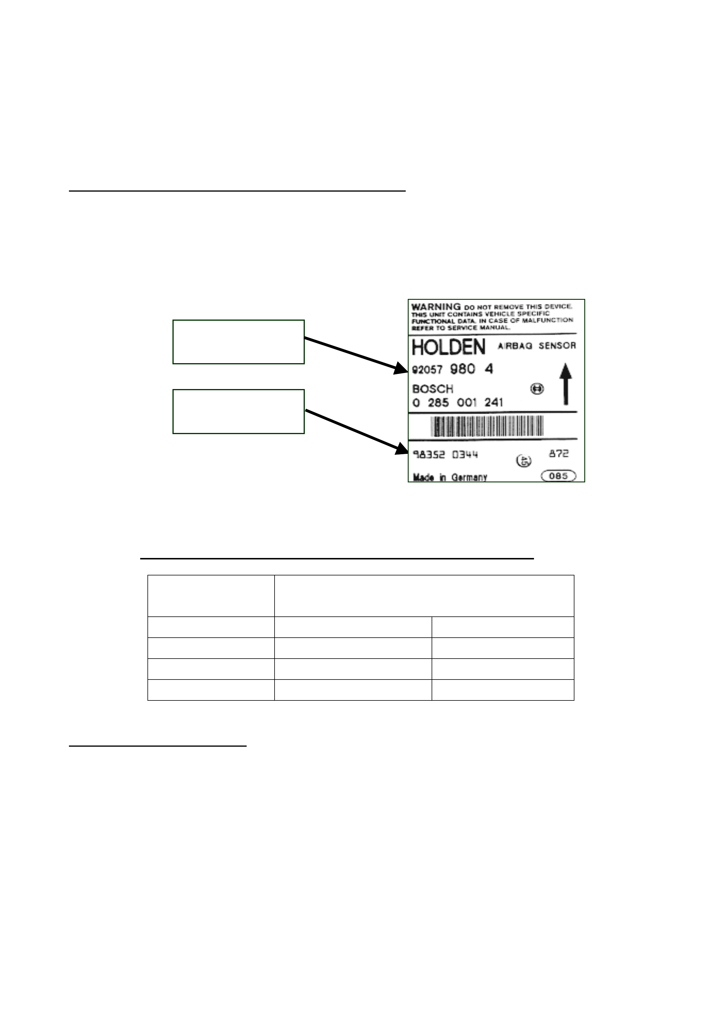
• Check the SDM part number and serial number as shown in Figure 1 below. If the ser ial
number falls within the affected range of ser ial numbers shown for that par t number (refer t o
Table 1 on the next pag e) , then the SDM must be replaced with a new one. Proceed to step
3. If the SDM serial number does not fall within the af fected r ange proceed to St ep 6.
Figure 1
• Table 1- Af f ect ed bat ches of SDM seri al numbers for each part number
SDM Part Number
Affected SDM Serial Numbers
From To
92075492
982510001
982880542
92075493
982400001
982930028
92075494
982450001
982940183
92057976
981920001
982930003
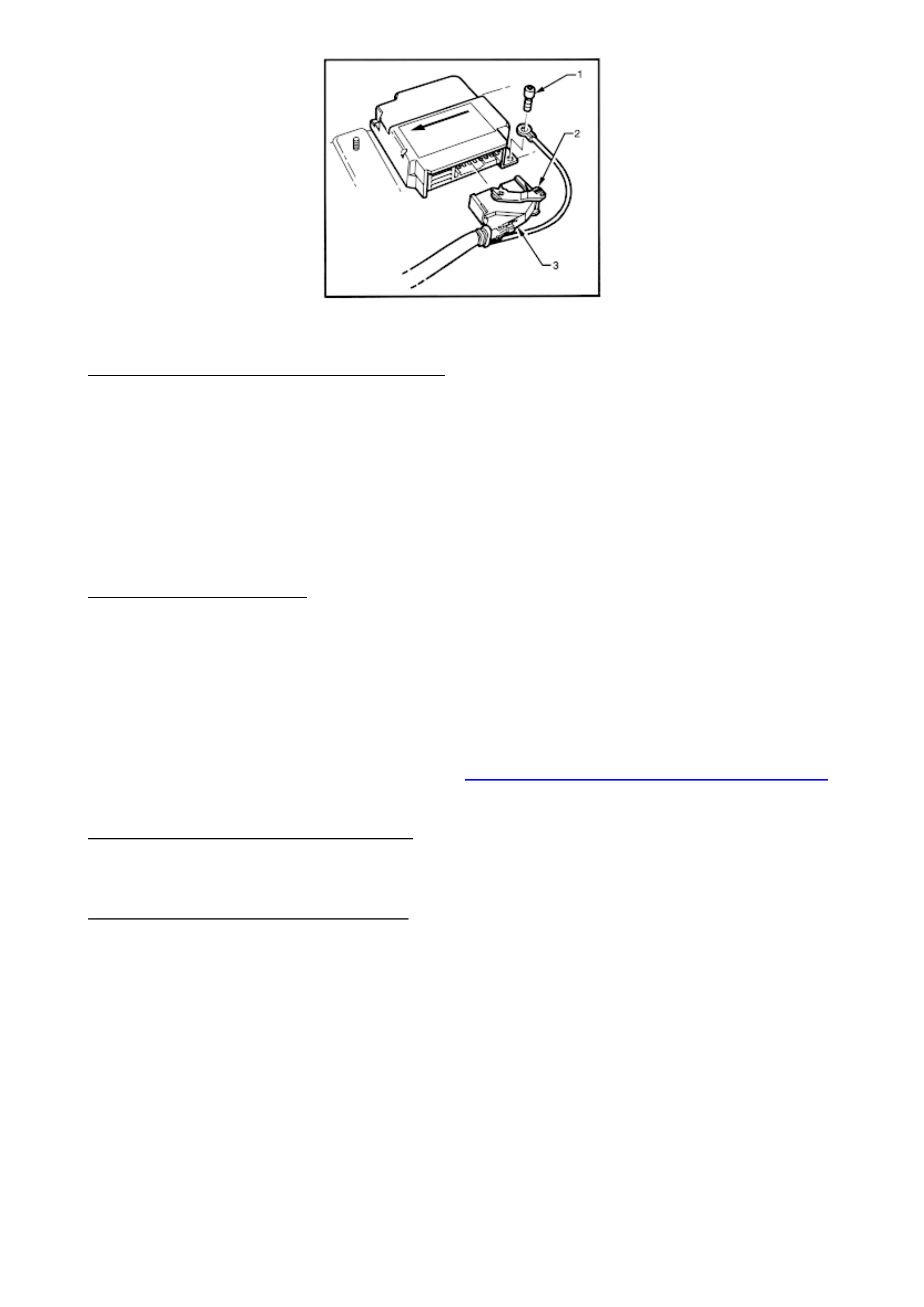
STEP 3. REMOVE SDM
• Disable the SRS system by disconnecting bot h t he battery earth and power leads and wait at
least 10 seconds bef or e per form ing any work on the vehicle.
CAUTION: T he SDM can maintain sufficient voltage t o cause SRS deployment for up t o 10
seconds aft er t he ignition switch is turned O FF or t he battery is disconnected.
• Using a number T30H Torx bit, Tool No. ETX30H and suitable holder such as Tool No.
J25359-8, loosen and rem ove the SDM to f loor attaching scr ew (1) with the earth lead attached
to it. Refer Figure 2 below.
• Lift up SRS wiring harness connector locking lever (2) and pull harness connector (3) out of
SDM. Refer Fig 1 below.
• Using the number T30H Torx bit, Tool No. ETX30H and suitable holder such as Tool No.
J25359-8, loosen and rem ove the r em aining two SDM to floor attaching screws.
• Remove SDM.
Holden Part Number
First 8 digits
SDM Serial Number
First 9 digits
5
Figure 2
STEP 4. INSTALL REPLACEMENT SDM
Installation of the new SDM is the reverse of r em oval procedur es, noting the following points:
• Ensure that the dir ectional arr ow on the SDM identificat ion label is point ing t owards the f r ont of
the vehicle.
• Install the SRS wiring har ness earth lead to t he left hand r ear SDM retaining screw.
• Using a number T30H Torx bit, Tool No. ETX30H and suitable holder such as Tool No.
J25359-8, tig hten SDM to floor att aching screws between 7-11 Nm.
• Connect the SRS wiring harness connector, ensuring that the connector is fully seated into
SDM module and the locking lever is locked down.
STEP 5. ENABLE SRS
• Reconnect both the bat tery power and earth leads.
• Switch ignition on, and observe the SRS warning lamp in the instrument cluster. The warning
lamp should be illuminated f or approximately 5 seconds. During this period the SDM performs
a wiring and self check .
• If no system faults ar e detected, t he SRS warning lam p will be switched off.
• If the warning lamp remains illuminated and an audible alarm chimes, or the warning lamp
illuminates 2 seconds after it was originally switched off , an SRS fault is present. Ref er to the
relevant volume of the VT Service Manual, 12M SUPPLEMENTAL RESTRAINT SYSTEM,
3 - DIAGNOSTICS.
STEP 6. REFIT CENTRE CONSOLE
• Reverse of r em oval procedur e.
STEP 7. APPLY CAMPAIGN LABEL
• Apply a ‘Campaign Completion’ label on the RHF door ‘A’ pillar between the door hinges and
submit a warranty claim.
6
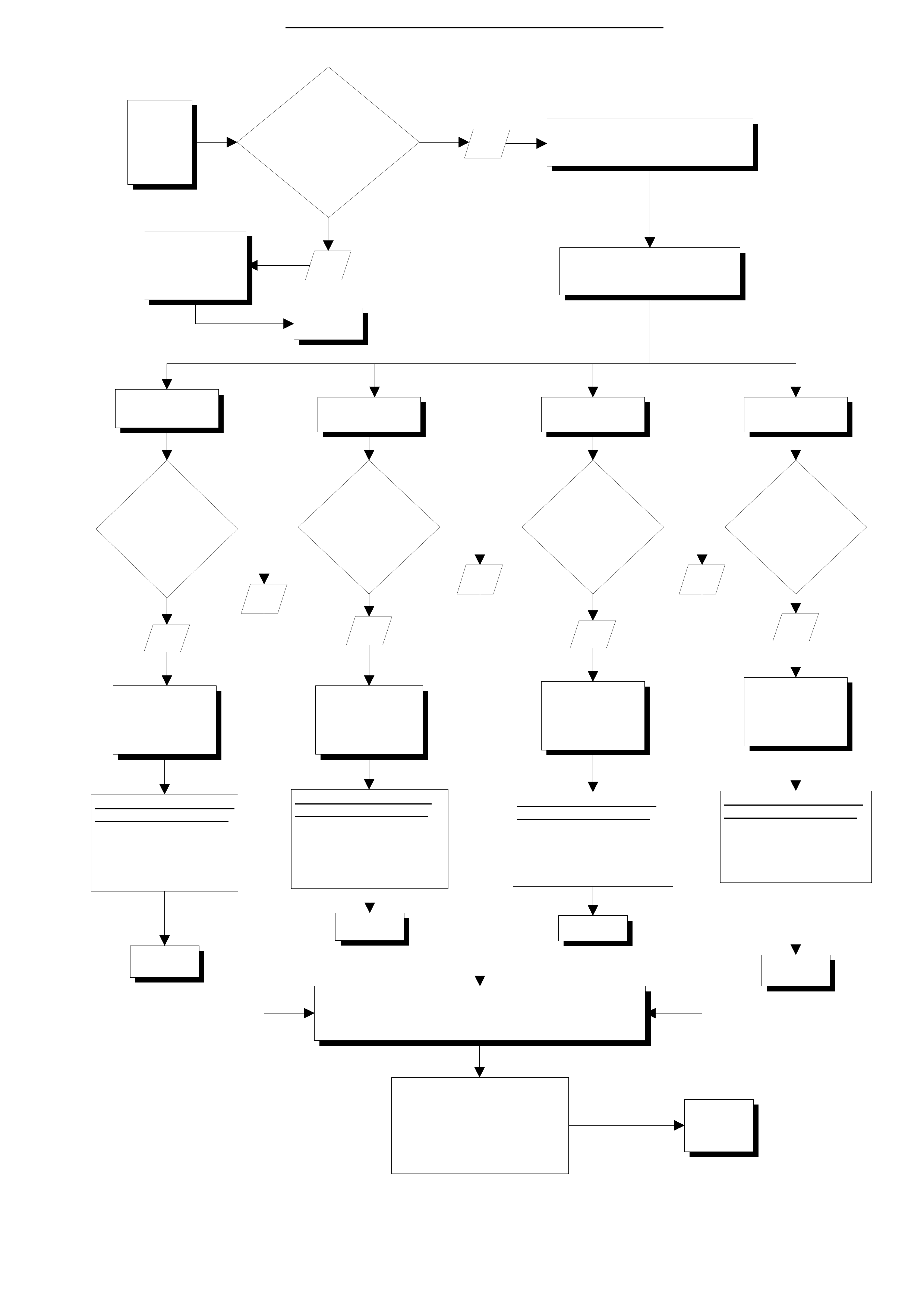
START
VEHICLE IS NOT
AFFECTED
(RETURN T O
CUSTOMER
REMO V E CE NT RE CONSOLE TO
DETERMINE SDM PART NUMBER AND
SERIAL NUMBER
SENSING & DIAGNOSTIC MODULE
(SDM) PART NUMBER
92075492 92075493 92075494 92057976
REPLACE SDM
WITH P ART
NUMBE R
92053352
REPLACE SDM
WITH P ART
NUMBE R
92057981
REPLACE SDM
WITH P ART
NUMBE R
92057980
APP LY CAMP AIGN L ABE L &
SUBMIT WARRANTY CLAIM
Lab our Op. : T 981002
Std Time : 1.0 Hrs
F/C : 96
Case T ype : 08
REPLACE SDM
WITH P ART
NUMBE R
92057976
IS SDM
SERIAL N U M BER
BETWEEN
982510001
AND
982880542
INCLUSIVE
IS
VEHICLE TAG
NUMBE R WIT HI N TAG
RANGE
L367025 TO L413138
INCLUSIVE?
IS SDM
SERIAL N U M BER
BETWEEN
982400001
AND
982930028
INCLUSIVE
IS SDM
SERIAL N U M BER
BETWEEN
982450001
AND
982940183
INCLUSIVE
IS SDM
SERIAL N U M BER
BETWEEN
981920001
AND
982930003
INCLUSIVE
APP LY CAMP AIGN L ABE L &
SUBMIT WARRANTY CLAIM
Lab our Op. : T 981002
Std Time : 1.0 Hrs
F/C : 96
Case Type : 08
APP LY CAMP AIGN L ABE L &
SUBMIT WARRANTY CLAIM
Lab our Op. : T 981002
Std Time : 1.0 Hrs
F/C : 96
Case Type : 08
APP LY CAMP AIGN L ABE L &
SUBMIT WARRANTY CLAIM
Lab our Op. : T 981002
Std Time : 1.0 Hrs
F/C : 96
Case Type : 08
SDM SERIAL NUM BER IS NOT IN THE AFFECTED RANGE
VEHICLE IS NOT AFFECTED -
DO NOT REPLACE SDM - Reinstall console
APPLY CAMPAIGN LABEL &
SUBMIT WARRANTY CLAIM
Labour Op. : T981001
Std Time : 0.8 Hrs
F/C : 96
Case Ty pe : 08
FINISH
FINISH
FINISH
FINISH
FINISH
YES YES
YES YES
NO
NO NO
NO
YES
FINISH
Attacmnent A - 99-H-04 SDM IDENTIFICATION PROCESS FLOW CHART

7
Attachment to Campaign Bulletin 99-H-04
SALMAT
MATERIAL ORDER FORM
Holden VT Series
Sensing and Diagnostic Modules
Fax No.: (03)-9251-6352
Attention: Kelly Sherriff
This dealership wishes to order additional Sensing and Diagnostic Modules for completion
of recall Campaign 99-H-04.
Please dispatch the parts detailed below, to this dealership, as soon as possible.
Part No. Description Amount
92057981
SDM version 6.2
Driver air bag
92057980
SDM version 6.2
Driver and Passenger air bags
92057976
SDM version 8.1
Driver, Passenger and Side air
bags
From Dealer Code: ___________ Date:_____________________
Dealership Name: ______________________________________
Dealership Service Manager: _____________________________________
(please PRINT your name)
Fax This Form To : SALMAT (03)-9251-6352

PRODUCT CAMPAIGN BULLETIN
99-H-05
July 9, 1999
SUBJECT : INSPECTION OF STEERING GEAR ASSEMBLY
MODEL : VT SERIES II – ALL LEVEL 1 & 2 VEHICLES
This bulletin is to advise Holden Dealerships of the initiation of a safety related campaign to
inspect the steering gear assembly on VT Series II, Level 1 & 2 vehicles (excluding Calais).
Description of Def ect
During assembly of the steering gear at the supplier, the rackbar and the inner ball joint housing
are staked (crimped) af ter the correct attaching torque has been achieved. It has been brought to
Holden’s attention that on a small number of steering gear assemblies, the final attaching torque
may not have been achieved and subsequent staking has not occurred.
Details of Affected Vehicles
Vehicles requiring this campaign action are VT Series II, Level 1 & 2 (excluding Calais) vehicles.
Vehicles requir ing this campaign action are all 1999 built VT Series II vehicles built bet ween
27/05/99 to 22/06/99 inclusive.
Vehicle Identification Numbers (VIN) L464495 to L473691 (6H8VTK35HXL464495 to
6H8VTK69HXL473691) inclusive, sets the range of vehicles affected.
5941 vehicles require inspection.
DEALERSHIP ACTION REQUIRED
Vehicles in Dealership Stock
Perform the necessary campaign action on any VT Series II vehicle held in Dealership stock that
falls within the affected VIN range. These vehicles must have this campaign action completed
befor e r etail delivery of the vehicle, or transf er to another dealer ship.
On Presentati on of Any VT Series I I Vehicle
On presentation of any VT Series II vehicle considered by the customer to be affected by this
action, or on presentation of a VT Series II vehicle for any reason, confirm that the vehicle falls
within the affected VIN range. If the vehicle requires campaign action, refer to the Detailed
Technical Inst r uctions included at the end of this bulletin.
In summary, the steering gear needs to be visually inspected to ensure that staking has occurred
which validates that the inner ball joint housing has been
torqued correctly into the rackbar. Both sides are staked simultaneously, so to prove the process,
only the left-hand side needs to be inspected as it is easier to access. If the inspection fails to
validate the process, the steering gear must be replaced. Upon replacing the steering gear, carry
out a f r ont-end alignm ent.
Aft er ‘inspection’ or ‘inspect ion and replacement’, apply a Campaig n Com pleted identif ication label
to the right hand front ‘A’ pillar and subm it a warranty claim using t he inform ation provided.

Vehicle Ident ification
All campaigned vehicles must have a Campaign Complet ed identification label applied to t he right
hand front ‘A’ pillar, between the hinges, with details of the campaign, 99-H-05, dealership code
and date completed, legibly entered on the label with a permanent ink pen.
Extra campaign ident ification labels ar e available free of charge from :
Moore Business Systems
Facsimile: (03) 9270 8900
Attention: Mr. Bob Curry
Quote stock No. SD 28156, on a Moore Business Systems ‘packaged goods’ order form (or
facsim ile if not available) for a box of 100 labels.
Vehicle List ings
Listings of affect ed vehicles shown in our customer nam e and addr ess files are included with this
bulletin. Should dealers have any infor m at ion to update the supplied list ings, please update listing
and fax to:
Holden Ltd
Att: P. Starick
War ranty Administration
Facsimile: (03) 9647 2525
Parts Information
Required par t s ar e to be ordered from HSPO.
The single part required to complete the inspection is the Inner Bellows Strap – Holden P/N
92140017.
In the unlikely event that a vehicle fails the inspection, the steering gear assembly must be
replaced. Replacement steering gears – Holden P/N 92057321 m ust be ordered through DCS via
the Emergency Order Process. Only order steering gear assemblies when a defective steering
gear has been ident ified.
Under no circumstances is a vehicle that fails the steering gear inspection to be returned to the
customer unt il a r eplacem ent steering gear assembly has been f it ted.
Owner Notification
Owners will be contacted directly by letter from Holden, providing details of the recall and
requesting them to arrange for the campaign action to be carried out. Following is a draft of the
customer letter.
Dear Holden Customer ,
At Holden we continually strive to enhance the ownership experience of our customers through
continuous product improvement, aftersales service and effective customer communication.
Holden’s foremost concern is the continued safety of our customers. Accordingly the recall
campaign described below is being under t aken as a safety precaut ion.
Holden has been alerted to the fact that in a limited number of vehicles within a determined
production range, a steering system component supplied to Holden may not have been
manufactur ed to the correct specification. In cert ain circumst anc es, this m ay resul t in poor or
unpredictable steer ing r esponse.

Our records show that your Holden VT Series II vehicle was manufactured within the vehicle range
which may include this component. It is therefore necessar y for you to contact a H olden dealership
of your choice as soon as possible to have your vehicle inspected and any necessary work
performed.
All work w ill be car ried out free of charge and your vehicle can be inspected w hile you w a it ,
provided the necessary ar r angem ents are made in advance w ith a Holden dealer . If on inspect ion
it is determined that your st eering syst em component requires replacement, the dealership w ill
endeavour to minimise any inconvenience t o you.
Holden has initiated this action as a precautionary measure to ensure the steering system of your
vehicle is functioning correctly.
We know that ef fect ive communicat ion is vital t o helping your under standing of the issues involved
and trust that this letter provides you with all the information you need. If you should have any
questions, please contact your dealer or call the Holden Recall Assistance Line - 1800 632 826,
and our operator s w ill be pleased to assist.
Thank you for your at t ention to this matter. Please accept our apologies for any inconvenience t hat
may be caused by this action.
Yours Sincerely
D. McMurray
Manager Customer Assistance
WARRANTY CLAIM INFORMATION
ON COMPLETION OF CAMPAIGN ACTION DEALERS MUST IMMEDIATELY SUBMIT A
WARRANTY CLAI M using the following data.
Description: Inspect Steering Gear
Labour Operat ion No: T981201
Standard T im e: 0.5 Hours
Failure Code: 96
Case Type: 08
In the event that t he steering gear is replaced:
Description: Inspect, Replace Steering Gear & Wheel Align
Labour Operat ion No: T981202
Standard T im e: 2.5 Hours
Failure Code: 96
Case Type: 08
The range of vehicles has been identified using t he VIN number. Please ensure all vehicle details
are included when submitting warrant y claim informat ion as per t he normal warranty processes.
War ranty claim submission is used to updat e our r ecord of cam paign completion and determines
whether furt her cust omer contact is necessar y to act ion all af fected vehicles. Please ensur e on
completion of the campaig n action that a warranty claim is submitted prompt ly. I n the event that
parts ar e r eplaced, REPAC will request ret ur n of all replaced par t s via the REPAC r epor t .
DETAILED TECHNICAL INSTRUCTIONS CAMPAIGN 99-H-05
The purpose of the inspection is t o locate a stak e m ar k that signif ies that the inner ball joint to
rackbar t or queing and subseq uent staking process was achieved by the supplier. The stak e m ark
is located in the k e yway type slot and located slightly above the normal field of view, made visible
by removing the tie rod inner bellows. T he st ake def or ms (crimps) the mating t hr eads, which aids
in preventing t he inner ball joint from r ot ating.
INSPECTION PROCESS:
1. Ensure the vehicle is a VT Series II, Level 1 or 2 vehicle (non-variatronic) and the vehicle is
within the affected ISO VI N r ange 6H8VTK35HX L464495 t o 6H8VTK69HXL473691.
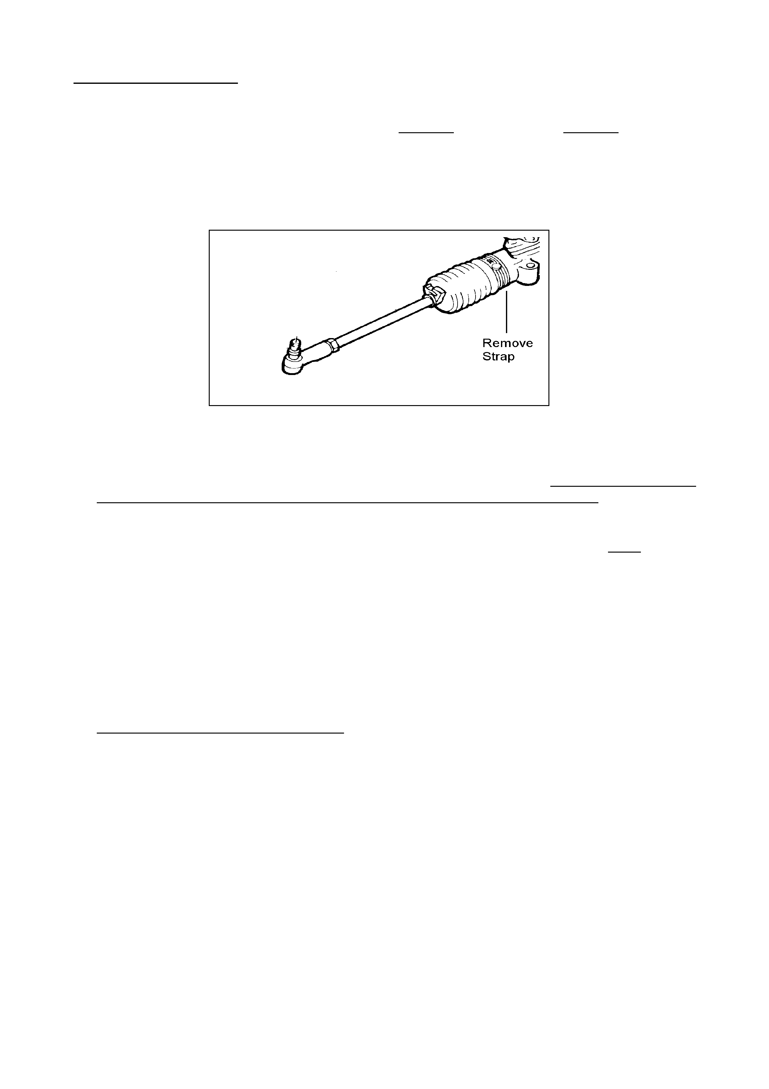
2. Raise the vehicle on a hoist and remove the inner left steering gear inner bellows strap that
secures the bellows to the steering gear main housing as indicated in Figure 1. Slide the
bellows outboard, off the steering rack housing, exposing the inner steering gear ball joint
housing. O nly the left side of the steering g ear needs to be inspected.
Figure 1
3. Locate the milled keyway on the rackbar by standing at the front of the vehicle and feeling for
the milled slot. The keyway is slightly above the normal field of view at the joining of the inner
ball joint housing and the rack bar. To inspect for the staking mark, a mirror and light source
must be used to locate the keyway otherwise proper inspection is not possible as indicated in
Figure 2 on t he following page.
4. Once this milled keyway has been located, the technician must identify a small surface
indentation in the keyway. Now move and stand behind the steering gear. Place the mirror
forward of the inner ball joint. From this position angle the mirror to enable a clear view of the
milled keyway. Refer Figure 2 and 3.
5. The stake indentation is approximately of rectangular shape in the milled keyway close to the
connection of the inner ball joint housing onto the rackbar. The dimensions of the stake mark
may vary slightly from gear to gear. The process has been completed if there is a definitive
surf ace ‘mark up’ within the keyway. Figure 3 is r epresentative (mir rored ref lection) of what the
technician will see.
Information Regarding the Stake Mark: During the manufacturing process, the tie rod / inner
ball joint assembly is attached to the rack bar via the threaded stud protruding from the inner
ball joint housing. Once the inner ball joint housing has been torqued correctly, the rackbar is
staked in the keyway area which deforms the mating threads increasing the screw friction of
the assembly.
NOTE: If during the tightening process the inner ball joint housing to rackbar attaching torque
is not reached, no st aking occur s , and t here will be no surface ‘mar k up’ of any kind evident. If
the surface at the base of the keyway is a smooth machined surface, then no staking has
taken place and t he r ack f ails the inspection.
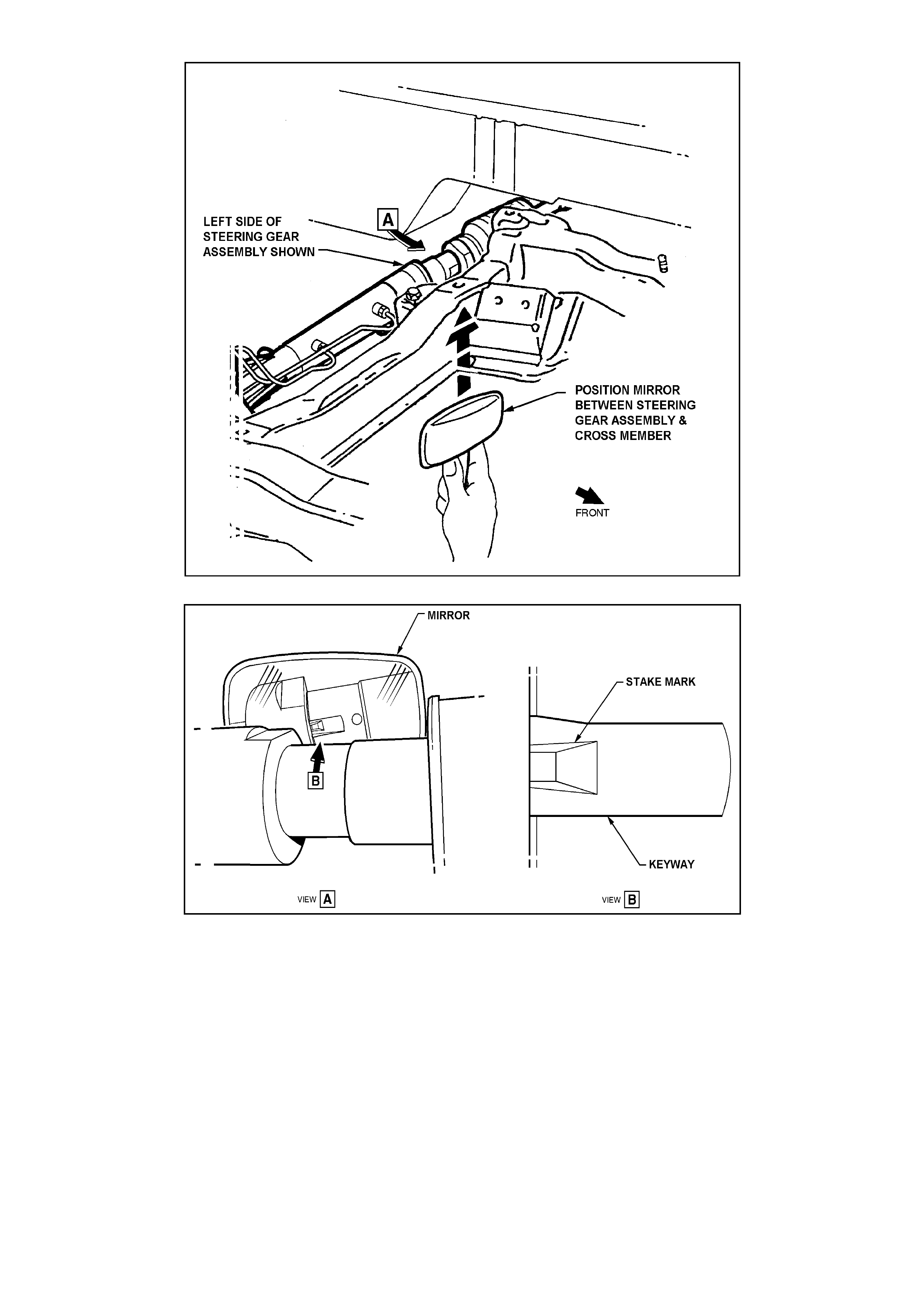
Figure 2
Figure 3 – Example of mirrored stake mark (may vary slightly between gears)

VEHICLES PASSING INSPECTION
• If the stake mark is positively observed and there is a definite change in the surface
characteristics of the r ackbar k eyway as indicated in Figure 3, t he vehicle passes inspection.
• Using part num ber 92140017 – Strap Bellows Inner, r eat t a ch t he bellows to t he st eer ing gear .
• Apply a Campaign Completed identification label to the right hand front ‘A’ pillar and submit a
warranty claim using the inform ation provided.
VEHICLES THAT FAIL INSPECTION
• If the stake mark is not positively observed and there is no definitive change in the surface
characteristics of the rackbar keyway, the steering gear must be replaced. After replacing the
steering gear, Holden P/ N 92057321, perf orm a f ront-end alig nment.
• Apply a Campaign Complet ed identification label to the r ight hand front ‘A’ pillar and submit a
warranty claim using the inform ation provided.
1
PRODUCT CAMPAIGN BULLETIN
99-H-06
November 4, 1999
SUBJECT : STEERING KNUCKLE
MODEL : 1999 VT SERIES II VEHICLES
This bulletin announces t he initiation of a safety relat ed cam paign on eig hty ( 80) 1999 VT Series II
vehicles in order to replace bot h St eer ing Knuckles.
DESCRIPTION O F DEFECT
Investigation has shown that a small number of Steering Knuckles may have been manufactured
in a specific batch where the casting operation may have caused casting defects to occur. This
may potentially comprom ise t he dur abilit y of the k nuckle.
DETAI L S O F AFFECTED VEHICLES
A total of eighty (80) vehicles are affected and require BOTH knuckle assemblies to be replaced.
These vehicles are identified in Table 1 below:
List of Affected Vehicles
L477764 L481425 L481557 L481589
L477999 L481426 L481561 L481592
L480047 L481427 L481562 L481593
L480858 L481428 L481563 L481595
L481194 L481461 L481564 L481596
L481342 L481513 L481566 L481597
L481365 L481538 L481567 L481599
L481402 L481540 L481569 L481600
L481404 L481542 L481570 L481603
L481406 L481543 L481571 L481604
L481408 L481544 L481572 L481605
L481410 L481545 L481574 L481609
L481411 L481547 L481576 L481610
L481412 L481548 L481578 L481611
L481413 L481550 L481579 L481613
L481415 L481551 L481580 L481614
L481416 L481552 L481583 L481620
L481419 L481553 L481585 L481621
L481420 L481555 L481587 L481622
L481421 L481556 L481588 L481630
Table 1
2
OWNER NO TIFICATION
A Holden representative has contacted each owner affected by this campaign by phone and
provided details of t he safety related cam paign. Your dealership has been nom inated to carry out
the campaig n r ect ification work and a booking dat e and time has been arranged.
Your cooperation and assistance in complying with the customer’s request via Holden CAS is
specifically requested so that customer inconvenience is minimised and the required action is
completed on all vehicles as quickly as possible.
DEALERSHIP ACTION REQUIRED
On presentation of the vehicle considered by the customer to be affected by this campaign,
confir m that the vehicle is listed in T able 1.
If the vehicle is listed in Table 1, both knuckles must be replaced. Refer to “Detailed Technical
Instruct ions Campaign 99-H- 06” .
CAMPAIGN COMPLETION IDENTIFICATION
All campaigned vehicles must have a Campaign Completed identif ication label applied to the rig ht
hand front ‘A’ pillar, between the hinges, with details of the campaign, 99-H-06, dealership code
and date legibly entered on t he label with a perm anent ink pen.
Extra campaign ident ification labels ar e available free of charge from :
Moore Business Systems
Facsimile: (03) 9270 8900
Attention: Mr. Bob Curry
Quote stock No. SD 28156 on a Moore Business Systems ‘packaged goods’ order form (or
facsim ile if not available) for a box of 100 labels.
PARTS INFORMATION
All requir ed parts (as listed below) will be supplied directly f rom Holden (via Salmat) in a pack age.
Parts will be shipped so they arrive prior to t he vehicle arr iving for this cam paign action.
Item Part No. Description Qty.
1 92078263 • Left Hand Steer ing Knuckle Ass. 1
2 92078262 • Rig ht Hand Steering Knuckle Ass. 1
3 11090821 • Bolt- St eer ing knuckle to str ut 4
4 92138205 • Nut- St eering k nuckle to str ut 4
5 92138554 • Nut- Ball joint to Steering knuckle 2

3
WARRANTY CLAIM INFORMATION
On completion of campaign action, dealers are requested to immedi ately submit a w arranty
claim.
Description: Replace Front Suspension Steer ing Knuckle (bot h sides)
Labour Operat ion No: T981301
Standard T im e: 2.5 Hours (includes Wheel Alignment)
Failure Code: 96
Case Type: 08
Please note that the fr ont wheel alignment check included in the repair procedur e is included in the
Standard T im e.
Also note that a 0.5 hrs bonus is included in the Standard Time to cover miscellaneous activities
associated with priority booking of customer s.
Please ensure all vehicle details are included when submitting warranty claim information as per
the normal warranty process.
Warranty claim submission is used to update our record of campaign completion and determines
whether furt her cust omer contact is necessar y to act ion all af fected vehicles.
Please ensure on completion of the campaign action that a warrant y claim is submitted promptly.
On completion of the campaign action ensure a defective material tag is attached to the steering
knuckle.
REPAC will request return of all replaced part s via the REPAC r epor t.
4
DETAI L ED TECHNICAL INSTRUCTIONS CAMPAIGN 99-H-06
Vehicles requiring this campaign action are eighty (80) 1999 built VT Series 2 vehicles listed in
Table 1.
DO NOT REPLACE THE STEERING KNUCKLES UNLESS THE TAG NUMBER IS LISTED ON
TABLE 1 AND YOU HAVE RECEIVED A CUSTOMER BOO KI NG DETAIL FORM .
STEERING KNUCKLE
REMOVE
1. Remove wheel cover (steel wheels) or centre
cap (alloy wheels).
2. Mark relationship of front road wheels to hub
and brake disc. Loosen then remove road
wheel attaching nuts. Remove the road wheels.
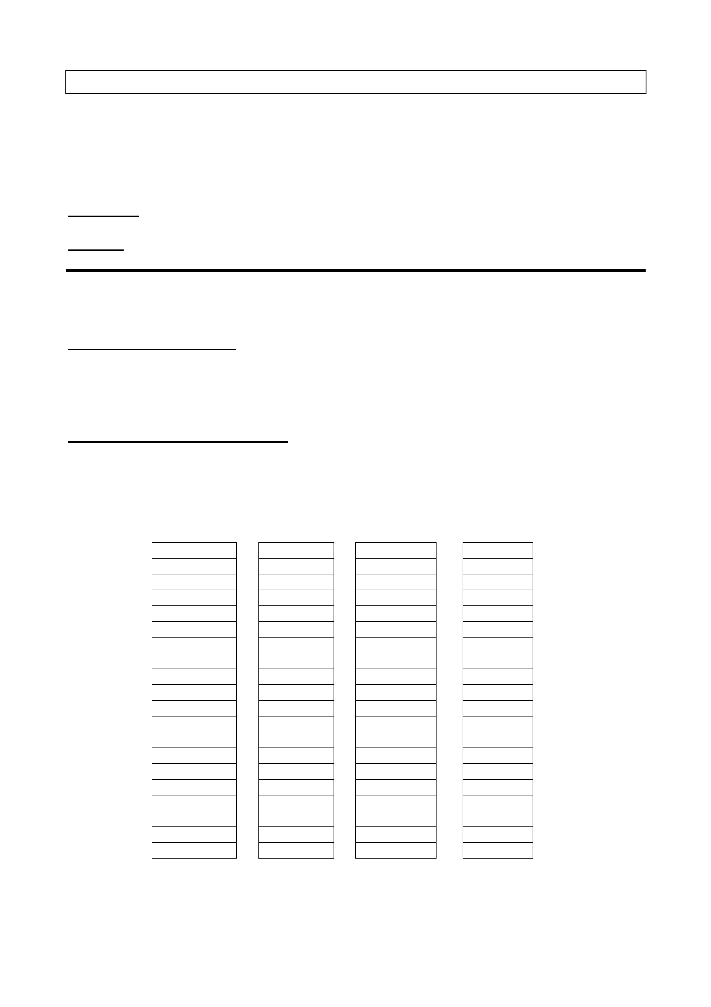
3. Remove brake caliper anchor plate retaining
bolts and washers (1), lift caliper assembly (2)
from brake disc. Position caliper (2) in such a
way that no strain is placed on the brake hose.
If necessary, tie caliper to the suspension
spring with a piece of wire. THE CALIPER IS
NOT TO HANG BY BRAKE HOSE.
4. While the brake disc to hub location is marked
in production, ensure that the disc to hub
position is carefully marked.
NOTE: This is necessary to overcome the
possibility of inducing a brake shudder condition
after reassembly.
5. Remove brake disc from the wheel bearing
hub.
NOTE: For vehicles equipped with ABS, disconnect
the wheel speed sensor connector (5) from the hub
sensor connector, by lifting the connector locking
tab and pulling on the connector to disconnect.
6. Using a commercially available 10 mm Allen
key socket and a suitable socket bar, loosen
each of the three bolts (4) holding the hub to
the steering knuckle.
NOTE 1: If the Allen key socket is too long to fit into
the front, upper hub bolt, then the lower strut to
steering knuckle nut (and bolt) will need to be
loosened and removed. Discard the removed bolt
and nut, as they must be replaced on reassembly.
NOTE 2: For the front lower hub bolt, turn wheel
outwards to provide sufficient clearance.
Figure 1
7. If the hub is a tight fit to the knuckle, it may be
necessary to loosen the three loosened bolts
and tap on the heads. DO NOT STRIKE THE
HUB.
8. Remove the three bolts and then the hub from
steering knuckle.
9. To remove the brake shield from the steering
knuckle, drill the heads from the three rivets
securing the shield to the steering knuckle.
NOTE: While the next series of illustrations show
the brake caliper, disc and shield still installed, the
service oper ations described ar e unaffec ted by this
background.
5
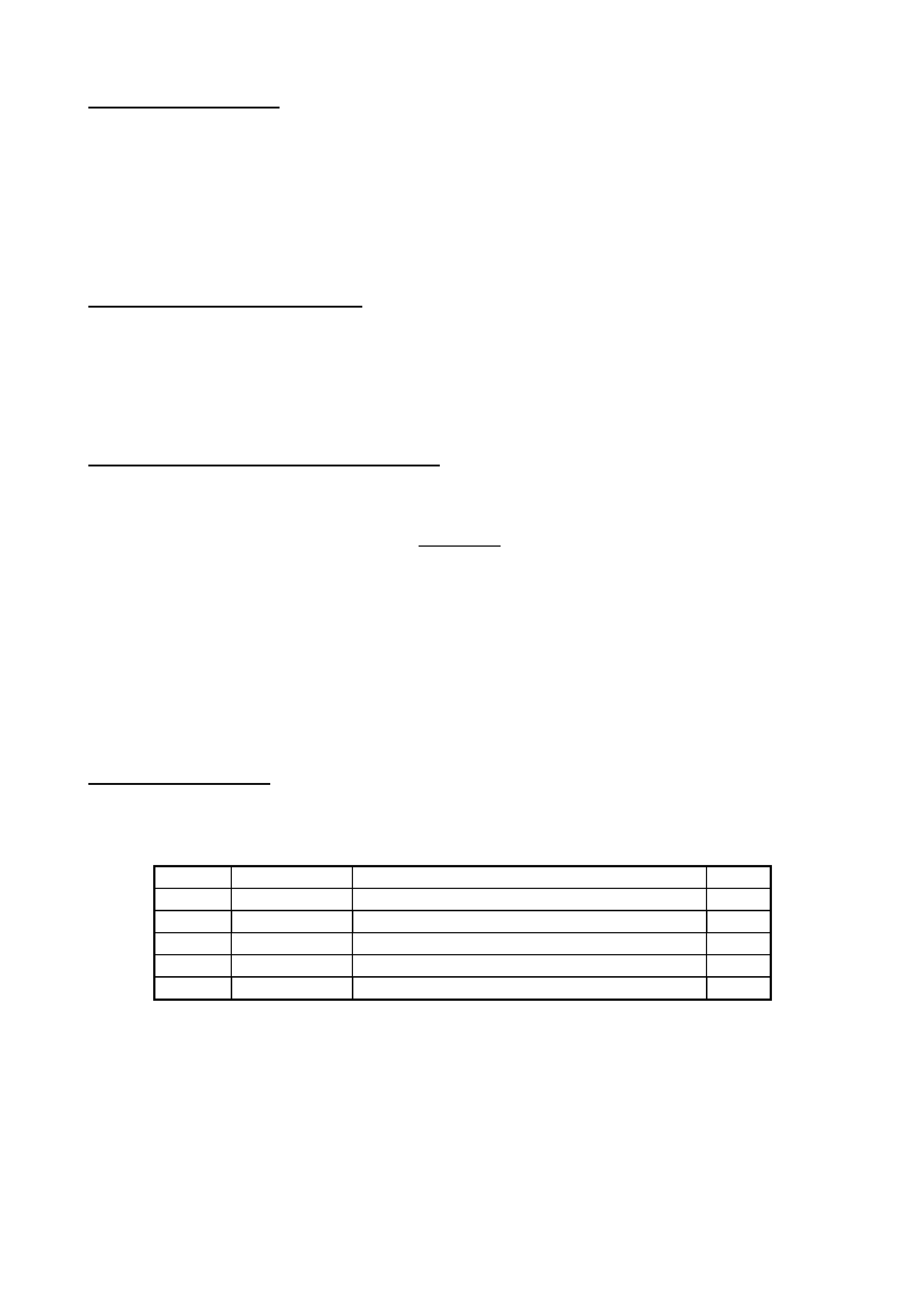
10. Remove the tie rod end s plit pin and loosen the
castellated nut (1) until the nut is flush with the
end of the tie rod ball joint stud.
11. Install T ool No. 7311 as shown, then us e a ring
spanner (2) to press stud out from steering
knuckle.
12. Fully remove the castellated nut to free the tie
rod end completely.
Figure 2
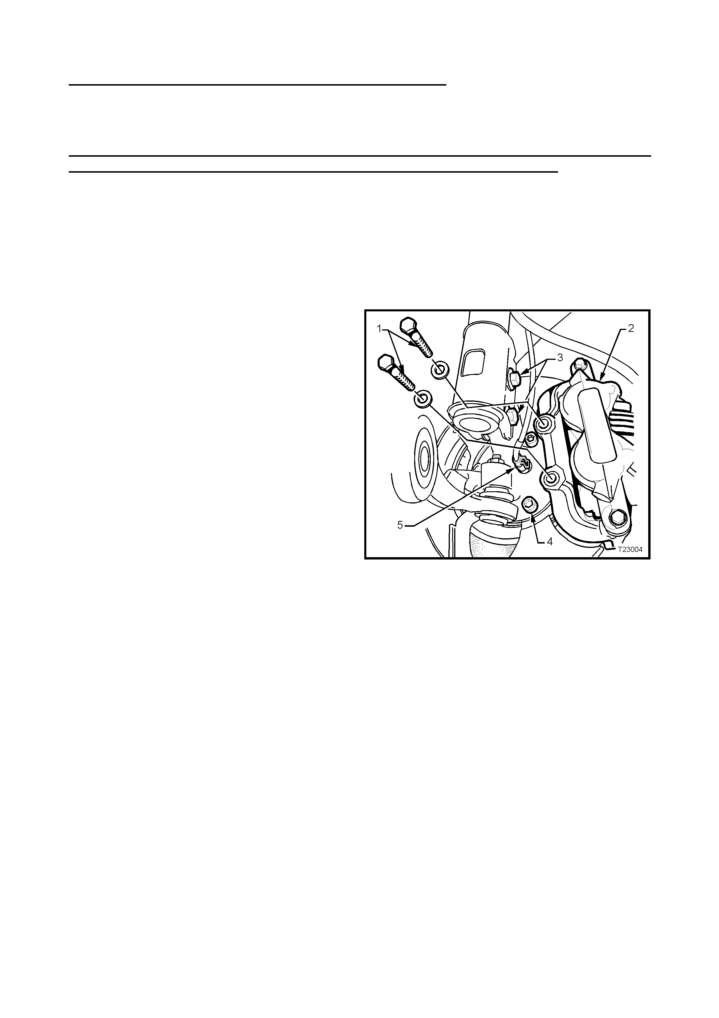
13. Loosen, rem ove and disc ar d the two lower strut
attaching nuts (2).
14. Remove the camber adjusting bolt (1) from the
original steering knuckle and reinstall into the
replacement knuckle, screwing in by
approximately the same amount.
Figure 3
15. Loosen the ball joint retaining nut (1) until the
nut is flush with the end of the ball joint stud
thread.
16. Install separation Tool No. E9332-A as shown,
then apply force to the top of the ball joint stud
by tightening the forcing bolt on the tool,
separating the ball joint from the knuckle.
NOTE: Once load is applied by the release tool
loading bolt, a sharp tap on the nut end of the tool
(E9332-A) will lessen the apply force required.
17. Temporarily jam the ball joint stud taper into the
knuckle to hold the stud, before fully removing
the retaining nut.
NOTE: Because the nut has micro-encapsulated
sealant applied to the threads, it must be replaced
after removal.
18. Separate the knuckle from the ball joint stud,
rem ove the two lower strut attaching bolts , then
remove the knuckle from the vehicle. Figure 4
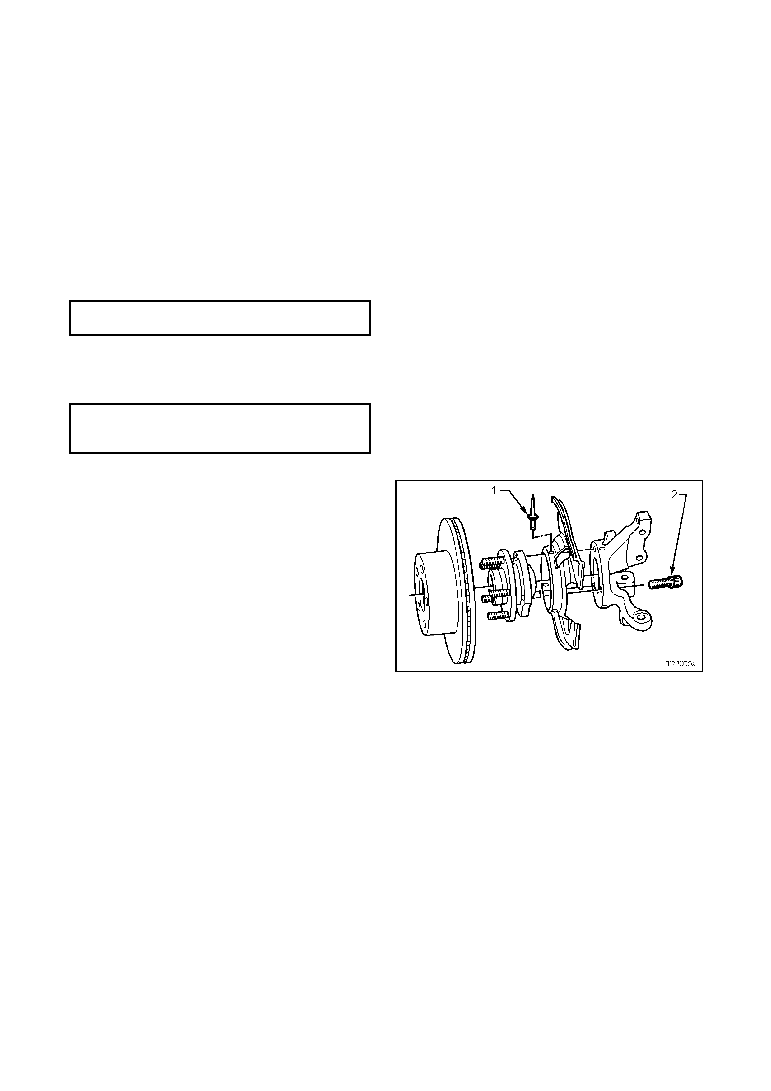
6
REINSTALL
Reinstallation is the reverse of removal procedures
except for the following:
1. Reinstall the steering knuc kle over the ball joint
stud, then install NEW lower strut to steering
knuckle, bolts and nuts but do not tighten fully
at this stage.
2 Using a suitable floor jack fitted with a block of
wood, position under the control arm, just
suff ic ient to suppor t the weight and j am the ball
joint stud taper into the knuckle.
3. Install a NEW self-locking nut to the ball joint
stud and tighten the nut to the correct torque
specification.
BALL JOINT STUD NUT
TORQUE SPECIFICATION 50 - 70 Nm
4. Install steering tie rod end ball joint stud to the
steering knuckle, reinstall the castellated
attaching nut and tighten to the correct torque
specification. Install new split pin.
TIE ROD BALL JOINT STUD
CASTELLATED NUT 50 – 80 Nm
TORQUE SPECIFICATION
All Models:
5. Secure the brake shield in place on the new
steering knuckle, using three, common pop
rivets (1), using a commercially available pop
rivet gun.
NOTE: Install the first rivet in the brake shield hole
with the round hole. This will ensure that the
clearance to brake caliper is correct.
6. Before installing the hub, inspect both mating
surfaces to make sure that they are clean and
free from burrs that could prevent correct
alignment of both parts, once installed.
Figure 5
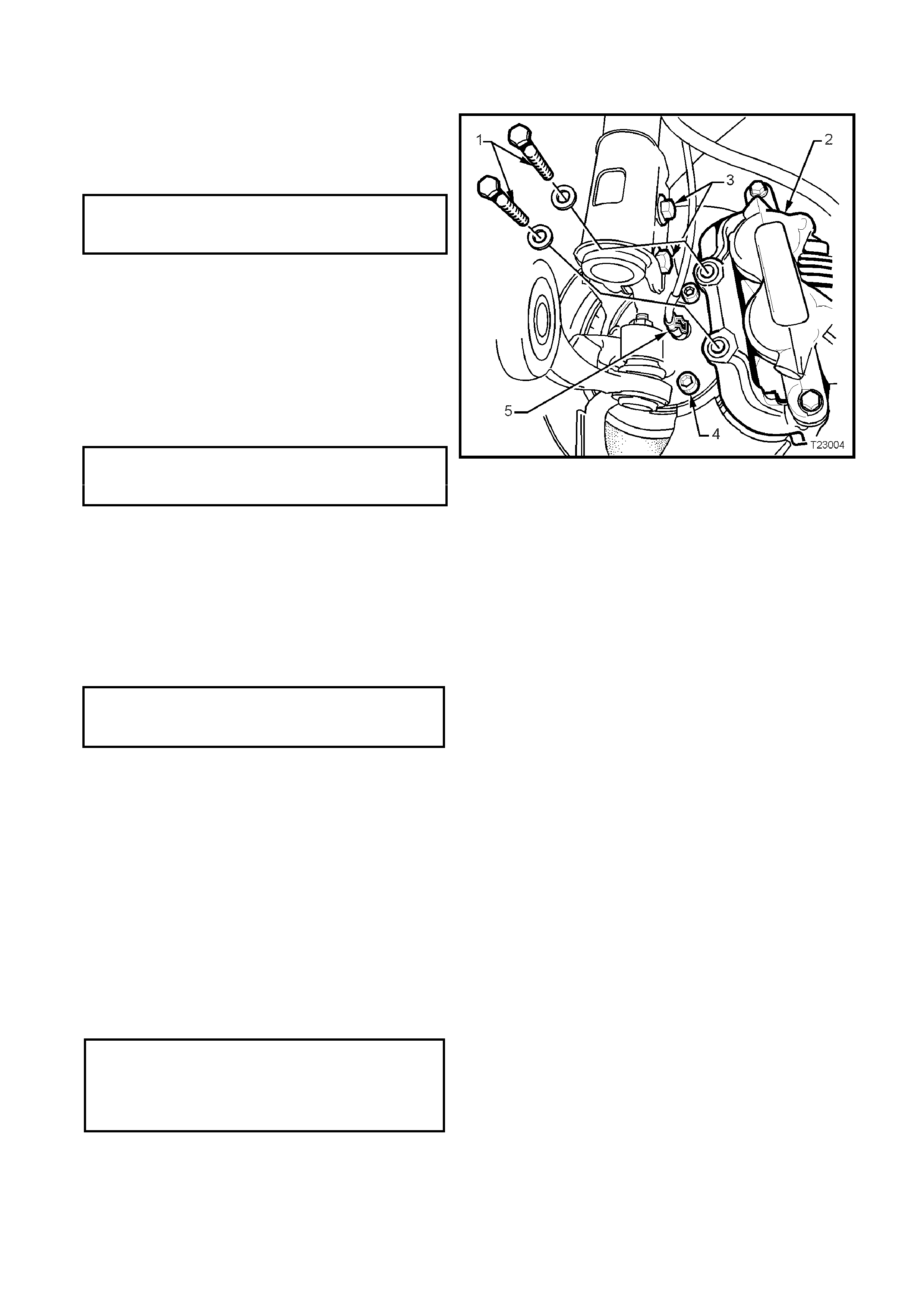
7
• Without ABS:
7. Install the hub assembly to the steering
knuckle.
8. Install the three attaching bolts (4) and tighten
to the correct torque specification.
FRONT HUB TO STEERING
KNUCKLE ATTACHING BOLT 100 - 115 Nm
TORQUE SPECIFICATION
NOTE: The three hub attaching bolts are micro-
encapsulated with thread sealant and are not to be
re-used more than three times. If in doubt, the bolts
should be replaced.
• With ABS:
9. Carefully align the sensor connection on the
hub with the hole in the steering knuckle, then
install the three hub attaching bolts (4) and
tighten to the correct torque specification.
FRONT HUB TO STEERING
KNUCKLE ATTACHING BOLT 100 - 115 Nm
TORQUE SPECIFICATION
10. Fit the wheel speed sensor connector (5),
ensuring that the locking tang is in place.
All Models:
11. Reinstall brake disc, aligning the marks made
before removal.
Figure 6
12. Reinstall the brake caliper and attaching bolts,
tightening bolts to the correct torque
specification.
BRAKE CALIPER ANCHOR 80 - 90 Nm,
PLATE RETAINING BOLTS then turn through
TORQUE SPECIFICATION 40° - 50°
13. Temporarily install road wheel/s, aligning the
marks made, following the brake disc runout
checks, then lower vehicle to the ground.
14. Bounce vehicle up and down several times to
settle suspension.
15. Check front wheel alignment, adjusting as
required. Refer to 2.1 WHEEL ALIGNMENT
CHECKING AND ADJUSTM ENT, in 3 FRONT
SUSPENSION, of the VT Series II Service
Information for the current procedure.
16. Following wheel alignment operations , it will be
necessary to raise the vehicle, remove the road
wheels once again and tighten the NEW
steering knuckle to strut bolts and nuts to the
correct torque specification.
STEERING KNUCKLE TO
STRUT ATTACHING Stage 1 85 Nm
BOLTS & NUTS Stage 2 100 Nm
TORQUE SPECIFICATION Stage 3 Turn
through 90°
17. After reinstallation of the road wheels and
aligning the marks made prior to removal,
install the nuts, lower the vehicle to the ground
and tighten road wheel attaching nuts to the

8
correct torque specification, working in a ‘star’
pattern. Do not over-tighten nuts.
ROAD WHEEL ATTACHING NUT
TORQUE SPECIFICATION 110 – 140 Nm
18. Refit wheel cover/centre cap.
19. Road test vehicle to ensure correct tracking
and smooth brake operation.
20. APPLY CAMPAIGN LABEL
• Fill out and apply a ‘Campaign Completion’
label on the RHF door ‘A’ pillar between the
door hinges and subm it a warrant y claim.
PRODUCT CAMPAIGN BULLETIN
99-H-07
November 4, 1999
SUBJECT: SEMI TRAILING ARM REPLACEMENT
MODEL: 1999 VT SERIES II (19 vehicles only)
This bulletin announces the initiation of a safety related campaign to replace the rear semi-trailing
arm assemblies (both sides) on nineteen (19) 1999 VT Series II vehicles.
Description of Defect
The integrity of a weld used in the rear semi-trailing arm manufacturing process may not have
been in accordance with Holden specifications and subsequently the durability of the semi-trailing
arm may be compromised.
Details of Affected Vehicles
Vehicles requiring this campaign action are nineteen (19) VT Series II vehicles and require both
semi-trailing arm assemblies to be replaced. Vehicle tag and ISOVIN numbers are listed below:
TAG ISOVIN
L486167 6H8VTK69HXL486167
L487159 6H8VTK35HXL487159
L487825 6H8VTL69HXL487825
L487831 6H8VTK69HXL487831
L487840 6H8VTK35HXL487840
L487921 6H8VTL35HXL487921
L487934 6H8VTL69HXL487934
L487938 6H8VTK69HXL487938
L487940 6H8VTK69FXL487940
L487955 6H8VTK69HXL487955
L487956 6H8VTK35HXL487956
L487967 6H8VTK35HXL487967
L487976 6H8VTK35HXL487976
L488008 6H8VTK69HXL488008
L488020 6H8VTK69HXL488020
L488022 6H8VTK69HXL488022
L488124 6H8VTK35HXL488124
L488130 6H8VTL69FXL488130
L488226 6H8VTK35HXL488226

Owner Notification
A Holden representative has contacted each owner affected by this campaign by phone and
provided details of the safety related campaign. Your dealership has been nominated to carry out
the campaign rectification work and a booking date and time has been arranged.
Your cooperation and assistance in complying with the customer’s request via Holden CAS is
specifically requested so that customer inconvenience is minimised and the required action is
completed on all vehicles as quickly as possible.
On Presentation of a VT Series II Vehicle
On presentation of a VT Series II vehicle considered by the customer to be affected by this action,
confirm that the vehicle is identified on the affected vehicle listing. If the vehicle is listed as
requiring campaign action, both rear semi-trailing arm assemblies must be replaced. Refer to the
Detailed Technical Instr uctions included at the end of this bulletin.
In summary, on identification of an affected vehicle, both rear semi-trailing arm assemblies must be
replaced with the supplied assemblies.
After r eplacement, apply a Campaign Completed identification label t o the rig ht hand front ‘A’ pillar
and submit a warrant y claim using the information provided.
Campaign Completion Identification
All campaigned vehicles must have a Campaign Completed identification label applied to the right
hand front ‘A’ pillar, between the hinges, with details of the campaign, 99-H-07, dealership code
and date legibly entered on the label with a permanent ink pen.
Extra campaign identification labels are available free of charge from:
Moore Business Systems
Facsimile: (03) 9270 8900
Attention: Mr. Bob Curry
Quote stock No. SD 28156 on a Moore Business Systems ‘packaged goods’ order form (or
facsimile if not available) f or a box of 100 labels.
Parts Info rmation
Required parts will be supplied directly fr om Holden. Parts will be shipped prior to the vehicle being
presented at the dealership.
Parts supplied per vehicle:
• Complete Left and Right Semi-Trailing Arm Assemblies (complete with tr unnion, bushing and
park brake assembly).
• Lock nuts x 4.

Warranty Claim Information
ON COMPLETION OF CAMPAIGN ACTION DEALERS MUST IMMEDIATELY SUBMIT A
WARRANTY CLAIM using th e following data.
Description: Replace Semi-Trailing Arm Assemblies (both sides)
Labour Operation No: T981401
Standard Time: 4.0 hours
Failure Code: 96
Case Type: 08
Please Note: A 0.5 hour bonus has been included in the Standard Time to cover miscellaneous
activities associated with priority booking of customer’s.
Please ensure all vehicle details are included when submitting warranty claim information as per
the normal warranty processes.
Warranty claim submission is used to update our record of campaign completion and determines
whether further customer contact is necessary to action all affected vehicles. Please ensure on
completion of the campaign action that a warranty claim is submitted promptly.
On completion of the campaign action, ensure a defective material tag is attached to the trailing
arms. REPAC will req uest r eturn of all r eplaced parts via the REPAC report.
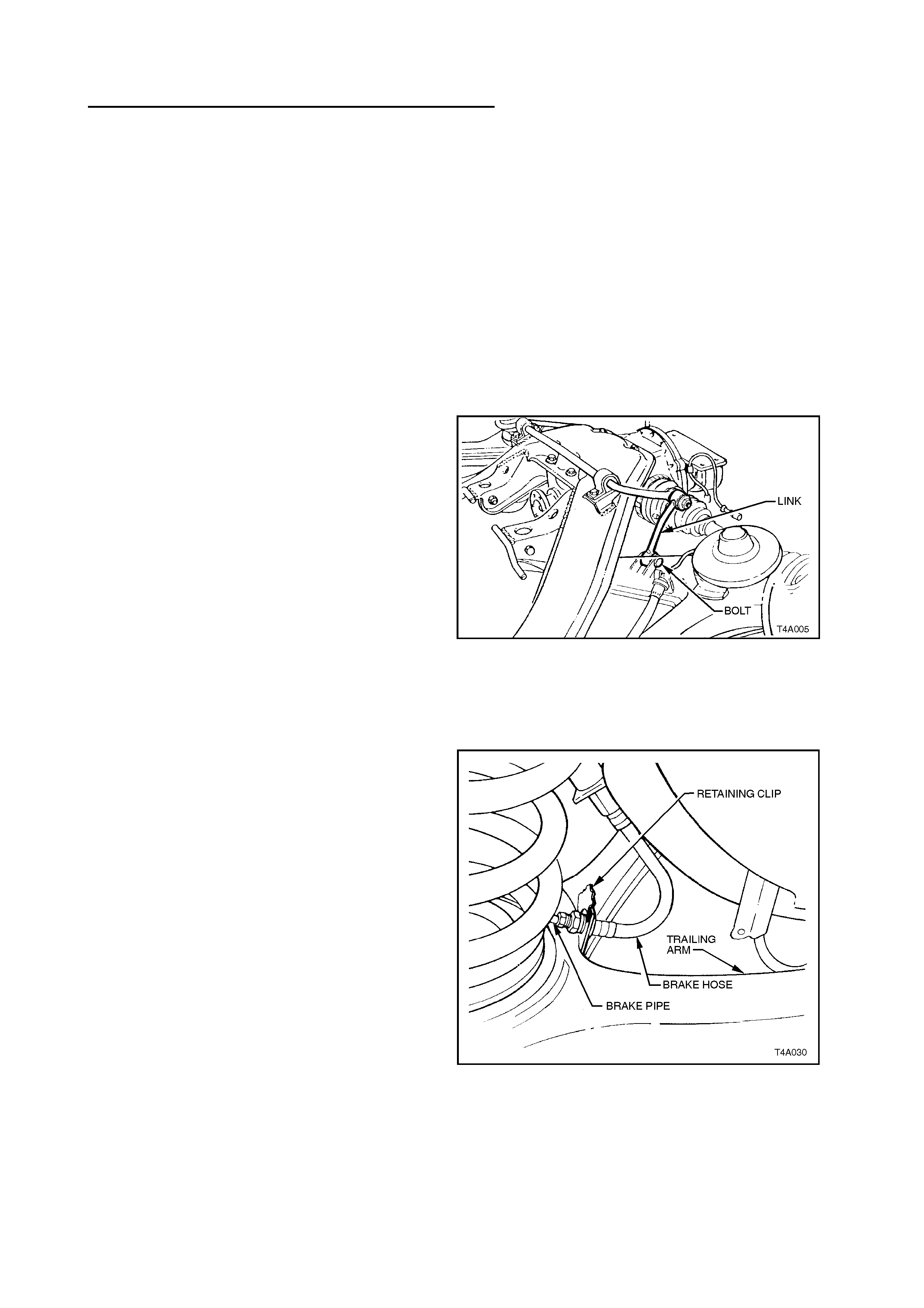
Detailed Technical Instructions Campaign 99-H-07
SEMI TRAILING AR M ASSEMBLY
REPLACEMENT
CAUTION: Whenever any component that
forms part of the ABS (if fitted) is disturbed
during Service Operations, it is vital that the
complete ABS system be checked, using the
procedure as detailed in DIAGNOSIS, ABS
FUNCTION CHECK, in Section 12L ABS &
ABS/ETC, of the VT Series I Service
Information.
NOTE: For this operation, new trailing arm to
crossmember lock nuts (supplied), must be used
on reassembly.
REMOVE
1. Using a floor jack under centre of differential
carrier, jack up rear of vehicle and place
safet y stands under bo dy rear jack ing points .
Refer to Section 0A GENERAL
INFORMATION of the VT Series I Service
Information for location of jacking points.
2. Remove wheel cover (steel wheels) or centre
cap (alloy wheels) from the vehicle side
where the spring is to be removed.
3. Remove road wheel attaching nuts and
remove wheel.
4. Loosen both stabiliser bar link, attaching
bolts and nuts, to reduce stress on the
insulator bus h.
5. Remove the stabiliser link to trailing arm
attaching bolt and nut from side of vehicle
where the trailing arm is being removed.
6. Remove rear brake hose retaining clip from
trailing arm to be removed. Pull brake pipe
and hose forward from bracket and
disconnect from trailing arm by lifting up
brake pipe through slot in bracket.
Figure 1
Figure 2
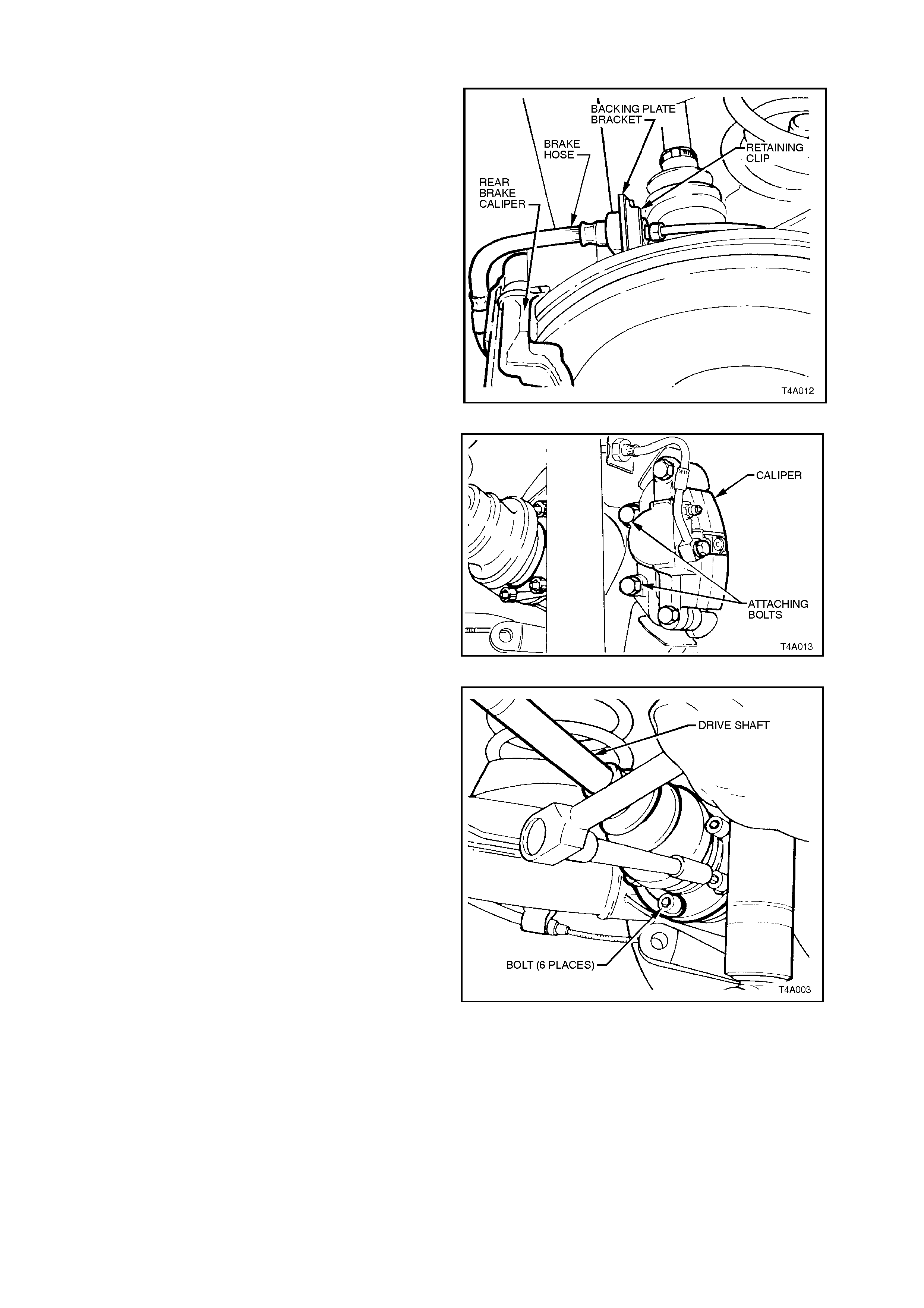
7. Remove brake hose retaining clip from brake
backing plate bracket. Disconnect rear caliper
brake hose from brake pipe and disconnect
pipe from backing plate bracket.
Plug open ends of brake pipe and hose to
prevent fluid loss and foreign matter entry.
Figure 3
8. Remove brake caliper anchor plate to trailing
arm attaching bolts and remove caliper from
disc. Support the brake caliper with tie wire
secured to the vehicle underbody. THE
CALIPER IS NOT TO HANG BY THE BRAKE
HOSE.
Remove brake disc.
NOTE: Should it be necessary to adjust the park
brake shoes to allow disc to be removed, refer to
Section 5A, STANDARD BRAKES, of the VT
Series I Service Information for the necessary
procedure.
Figure 4
9. Hold the trunnion assembly hub from rotating,
loosen the six drive shaft outer constant
velocity joint to trunnion flange attaching bolts,
using an 8 mm Allen key socket and bar.
Figure 5
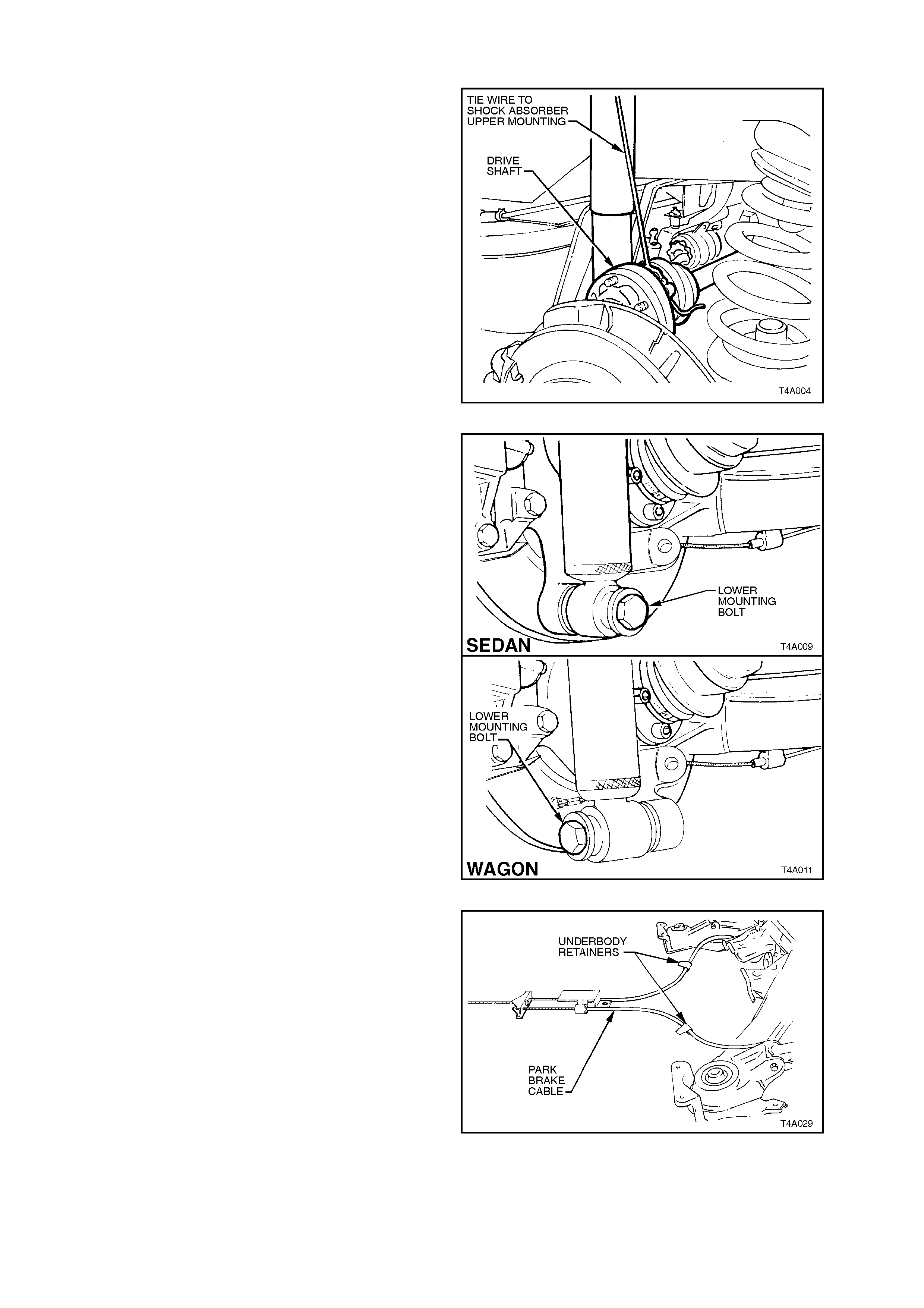
Disconnect drive shaft from flange and lift
upward. Keeping drive shaft vertical and, using
a piece of wire, tie up drive shaft to lower end
of shock absorber upper mounting.
NOTE: Bruising to the inside of the drive shaft
constant velocity joint boots will occur if the trailing
arm is lowered any further. This will lead to
prem ature failure of the bo ot and ev entual f ailure of
the joint if unchecked.
For this reason, it is important that the constant
velocity joint is disconnected from the trunnion
flange before removing the shock absorber lower
mounting bolt.
Figure 6
10. Position floor j ac k under trai li ng arm. Rais e j ack
slightly to take spring load off trailing arm.
Disconnect rear shock absorber lower
mounting bolt from trailing arm, then pull the
lower end of shock absorber from trailing arm.
Figure 7
11. Set park brake in fully released position.
Release each of the underbody to park brake
cable retaining clips and free cables.
Figure 8
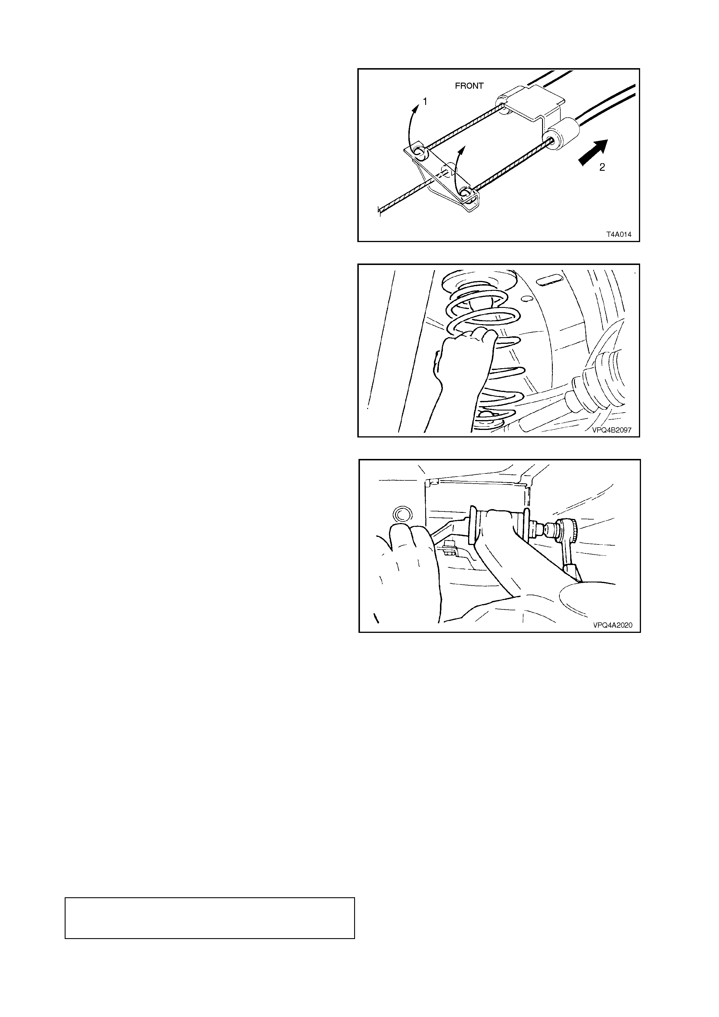
12. Remove park brake outer cable retaining
bracket bolt from the vehicle underbody.
13. Pull each park brake inner cable forward and
up, (1) out of the cable retainer. Pull the outer
cable rearward (2) to remove from the
underbody retainer.
Figure 9
14. Lower jack and if necessary, push down on
trailing arm and remove rear spring and
insulators from vehicle underbody and trailing
arm.
Figure 10
15. Loosen and remove trailing arm to rear
crossmember attaching bolts and nuts, remove
trailing arm and discard nuts.
Figure 11
REINSTALLREINSTALL
The reinstallation of the supplied trailing arm
assembly is the reverse of removal procedure, with
the exception of the following steps:
1. Install trailing arm to rear crossmember, but do
not fully tighten attaching bolts at this stage.
NOTE: Always use new self-locking nuts.
2. Index brake disc to trunnion so minimum runout
specification is achieved (less than 0.080mm).
Refer to VT Series II Service Information,
Section 5A, STANDARD BRAKES, for the
necessary procedure.
3. Tighten brake caliper anchor plate-to-trailing arm
attaching bolts to the correct torque
specification.
BRAKE CALIPER ANCHOR PLATE
TO TRAILING ARM ATTACHING 70 - 100 Nm
BOLT TORQUE SPECIFICATION

4. Tighten shock absorber and stabiliser bar
attaching bolts and nuts to the correct torque
specifications.
NOTE: Sedan and station wagon torque
specifications are the same.
SHOCK ABSORBER LOWER
MOUNTING BOLT 105 - 125 Nm H
TORQUE SPECIFICATION
STABILISER BAR LINK TO
TRAILING ARM ATTACHING BOLT 90 - 105 Nm H
TORQUE SPECIFICATION
5. Tighten dr ive shaft ou ter consta nt velocit y joint
to trunnion flange attach ing bolts to the correct
torque specification.
DRIVE SHAFT CONSTANT 50 Nm, plus
VELOCITY JOINT TO TRUNNION 60° - 75°
TORQUE SPECIFICATION turn angle
Important: Those torque settings marked as H
must only be carried out with the weight of the
vehicle on the four wheels and at curb weight.
6. Bleed rear brakes and ch eck for leak s. For the
recommended procedure, refer to
Section 5, BRAKES, of the VT Series I
Service Information.
7. Install road wheels and fit attaching nuts.
8. Remove safety stands and lower vehicle.
9. Tighten road wheel attaching nuts to the
correct torque specification.
ROAD WHEEL ATTACHING NUT
TORQUE SPECIFICATION 110 - 140 Nm
10. Refit wheel covers/centre caps.
11. With vehicle in kerb height position, tighten
trailing arm to crossmember attaching bolts to
the correct torque specification.
TRAILING ARM TO REAR
CROSSMEMBER ATTACHING NUT 95 - 105 Nm
TORQUE SPECIFICATION
12. Adjust park brake as required.
13. Fill out and apply a Campaign Identification
Label – SD28156.