
111999999999 SSSEEERRRVVVIIICCCEEE TTTEEECCCHHHLLLIIINNNEEESSS
© 2006 GM Holden Ltd. A.B.N. 84 006 893 232
Service Department
A “HOLDEN” Product.
BRISBANE SYDNEY MELBOURNE ADELAIDE PERTH
MONTEREY BULL BAR (March 1999)
MONTEREY/ JACKAROO GROUP 0B
The current bull bar (part no. 92141571) released for Jackaroo and Monterey models incorporates turn
signals and park lights which are necessary to comply with regulations.
W hen the bull bar is installed the original bumper is discarded. On the Monterey model the bumper bar
incorporates fog lamps and these will also be discarded as no provision has been made in the bull bar for
their fitment.
RODEO FAN MOTOR / RESISTOR FAILURE (March 1999)
1999 RODEO GROUP 2
Some Rodeo vehicles may experience repeated heater fan resistor or motor failure due to moisture entry.
Moisture can enter the motor assembly through the cowling screw on the passenger
side (directly above motor). Ref er to diagram 1on the following page.
Please remove screw, apply silicone / sealant and refit screw.
Diagram 1
RODEO 4X4 & 4X2 AIR CONDITIONER KITS INTERCHANGEABILITY (March 1999)
1999 RODEO GROUP 2
Confusion has arisen on the interchangeability of the A/C kit applicable for Rodeo vehicles. The A/C kit part
number M41682 can be installed on either the 4x2 or the 4x4 vehicle. A/C kit part number 92141532 is for 4
x 4 only, and will be phased out once all stock is exhausted.

JACKAROO ANTI THEFT & IMMOBILISER (March 1999)
JACKAROO GROUP 12
1998 UBS THEFT DETERRENT SYSTEMS
Two separate theft deterrent systems are provided on the 1998 Jackaroo & Monterey:
• Anti-theft Warning – provided by the Anti-Theft Alarm/Keyless Entry system fitted to Jackaroo SE and
Monterey.
• Drive-away deterrent – provided on all models by the Engine Immobiliser system.
When diagnosing a vehicle concern, it is important for the technician to have a basic understanding of the
operation of each system and be aware of the correct diagnostic procedures.
The diagnostic procedures are specific for each system. Failure to follow the correct procedure will result in
lost time, possible replacement of serviceable components and an aggrieved customer.
To determine which system is at fault, the technician must remember two very important points:
• Except in exceptional circumstances, the Anti-theft Warning/key-less entry system cannot prevent the
vehicle from starting .
• The Engine Immobiliser system cannot prevent the doors from locking or unlocking via the remote
keypads or the mechanical key.
Having determined which system has failed, the correct diagnostic procedures can then be applied:
• Anti-Theft Alarm/ Keyless Entry System diagnosis is performed by referring to the charts in section 8D
– 242/261 of the service manual.
• Engine Immobiliser system diagnosis is performed with the aid of TECH-2 and the LATEST version of
the program card.
To assist in the understanding of the operation of these systems, a brief description of each follows.
ANTI- T HEFT & KEYLESS ENTRY SYSTEM
The basic central locking system and anti-theft alarm system hardware carried over from the 1997
Jackaroo. The keyless entry system fitted to SE and Monterey was new for 1998 Australian vehicles.
Anti-theft/Key-less Entry Module
The Anti-theft Alarm system and Key-less Entry share the same module. The module is located in the
center dash, immediately above the PCM, and is identified by a black ABS plastic casing and a green 22-pin
harness connector.
The circuit consists of the ignition switch, anti-theft module, anti-theft horn, anti-theft indicator light, front
door and tailgate key switches, door lock switches, courtesy light switches, door lock act uator s, engine hood
switch, and A/T mode switch.
The module uses an “earth-sensing” system for monitoring of the doors and engine hood status – opening
of any of these items will cause the relevant circuit in the module to be grounded, triggering the alarm
function. The key switches & lock actuators provide the input signals required for arming or disarming the
system.
As a further safe guard, the front door locks and tailgate lock incorporate ‘tamper’ switches that will also
ground the relevant circuit should the lock be forced or ‘pulled’.
Arming Operation
• Remove the key from the i gnition switch.
• Ensure all doors and the engine hood are closed.
• Lock the vehicle with either the mechanical key or the remote keypad.
• 30 seconds after locking the vehicle, the Anti-theft LED will begin to flash.
• The system is now armed with the module monitoring all doors and the engine hood.
• Triggered Operation
Anti-theft LED
Once triggered, the system will
• Pulse both the anti-theft and vehicle horns at a rate of one pulse per second.
• Flash all indicator lig hts at a rate of once per second.
• Disable the starter motor relay.
Triggered operation will continue for approximately 30 seconds. At the end of this period, the system will
rearm itself, and continue to monitor the relevant circuits.
Disarming Procedure
• Unlock the vehicle with the correct mechanical key or the remote key.
• If the alarm is sounding, insert the key into the ignition switch and turn the switch to the “ACC” position.
Keyless Entry
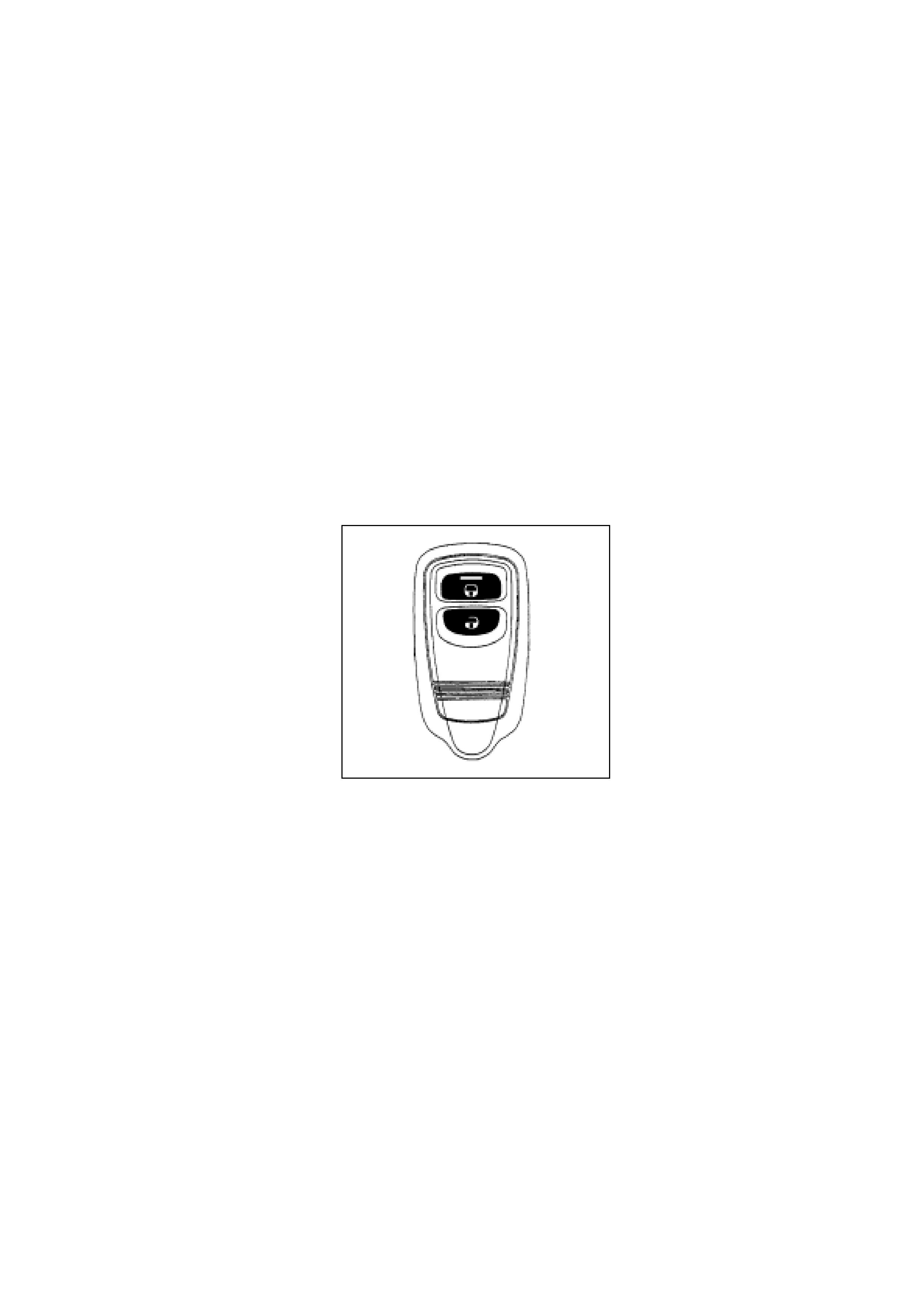
The keyless entry circuitry is incorporated in the anti-theft module. Two two-butt on radio rem ote transmitt ers
are initially prog rammed into the module.
Up to four transmitters can be programmed into the module, should an attempt be made to program a fifth
key, the module will clear the first key code.
The transmitters are of the rolling code type, each transmission incrementing the code.
The minimum range of the transmitters is specified at 3 meters, although this can vary with proximity to
other radio or telephone transmitting towers. The estimated service life of the two lithium CR2016 cells in
each remote is at least two years with an average usage of 10 lock/unlock cycles per day.
The key-less entry system is powered through the interior light circuit via the 10-amp ‘Room’ fuse (C16),
located in the I.P. fuse panel. This fuse must be fitted during pre-delivery inspection of the vehicle. Failure of
the fuse will disable the key-less entry function and dome light operation.
The anti-theft horn performs an ‘answer-back’ function when the remote keys are used. Locking the vehicle
will cause the anti-theft horn to ‘chirp’ once. Unlocking will result in the anti-theft horn ‘chirping’ twice.

As an additional night-time safety measure, the dome light is turned ‘ON’ for 30 seconds when the vehicle is
unlocked. Should the driver so desire the anti-theft horn ‘answer-back’ function can be disabled.
Anti - Theft & Keyless Entry System – Initial Diagnosis
PIN FUNCTION PIN FUNCTION
1 Door switches – front 12 Engine hood switch
2 Door switches – rear 13 Key switch detect – front
doors/tailgate
3NA 14NA
4 NA 15 Key lock switches – unlock signal
5 Key Lock switches – lock signal 16 Lock tamper switch signal
6 Door switch – tailgate 17 Ground
7 Horn relay 18 Power – ignition switch – ‘ACC.
ON’
8 Anti-t heft hor n 19 Anti-t heft I ndicator lam p
9 NA 20 Door switches – rear – dome
10 Power – B+ 21 Hazard Warning lamp relay
11 Door switches – unlock – all doors 22 Starter motor relay
Anti-Theft Alarm/Keyless Entry System diagnosis is performed by referring to the charts in section 8H of the
service manual.
However, there are several quick initial checks the technician can perform to narrow down the area in which
the fault has occurred.
Vehicle will not lock/unlock with the remote keypads
• Does the dome light operate when a door is opened?
- If ‘NO’ check the Fuse C16 and the dome light switch position.
• Does the vehicle lock/unlock with the mechanical key and the driver door switch?
- If ‘YES’ then the central locking system is functioning.
Anti-Theft/Keyless Entry Harness Connector Pin Arrangement
- Face View -
1 2 3 4 5 6 7 8 9 10
11 12 13 14 15 16 17 18 19 20 21 22

• Can the alarm system be ‘armed’ with the mechanical key?
- ‘NO’ would indicate a possible incorrect door/engine hood input to the module.
‘YES’ would point to a keypad fault or failur e of the relevant circuit within th e module.
• Perform the “Keypad Test” as outlined on the following page.
Keypad Testing
As the keypad transmits a FM radio signal, the vehicle radio can be used to check the operation of the
keypad. The actual frequency of the keypad may vary from 101mHz to 106mHz. It is best to commence
testing with the radio set on 101mHz.
• Turn the radio ‘ON’ with the frequency set to 101mHz, and the volume control at about ½ level.
• Hold the keypad against the base of the antenna then press and hold the keypad ‘lock’ button.
• If a pulsing signal is heard from the speakers, the keypad is functioning.
• Should you fail to hear a signal, try 102mHz and so on up to 106mHz.
• If you have tried all the frequencies without hearing a signal, replace the two CR2016 lithium cells in t he
keypad and repeat the frequency test.
Keypad Programming
The programming sequence appears in section 8D - 258 of the 1998 UBS Workshop Manual.
Four program modes are available:
• ID Code New Registration – erases all programmed codes and registers new code.
• ID Code Additional Registration – registers additional ID codes.
• ID Code Check – checks how many ID codes are programmed in the module.
• Answer Back Change Mode – enables/disables the horn answer back function.
Note:
It is important to keep within the time frame stipulated for each operation – the system will time-out and
abort the programming sequence if these times are exceeded.
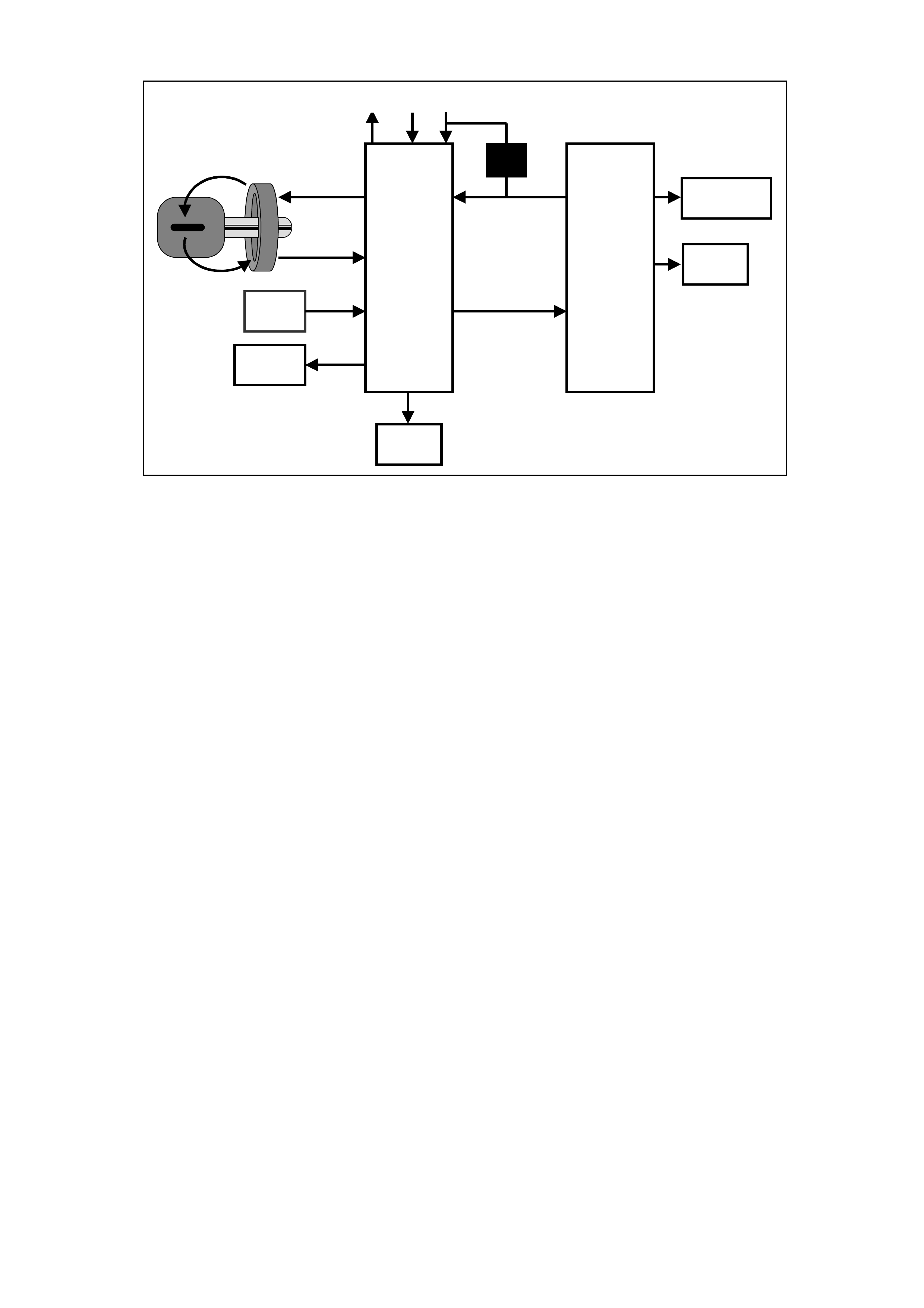
IMMOBILI SATION SYSTEM
The Engine Immobiliser system is the second of the two independent theft deterrent systems fitted t o 1998
UBS vehicles. The system is designed to provide “Drive-away” protection by electronically disabling the fuel
and ignition systems and the starter motor relay. It is a passive system, r equir ing no action on the part of t he
driver other than removing the ignition key from the switch.
The system uses a conventional mechanical-cut ignition key containing a miniature transponder in the
plastic handle. Within the transponder is an antenna and an integrated circuit. Each transponder is
programmed with it’s own specific ID code during manufacture.
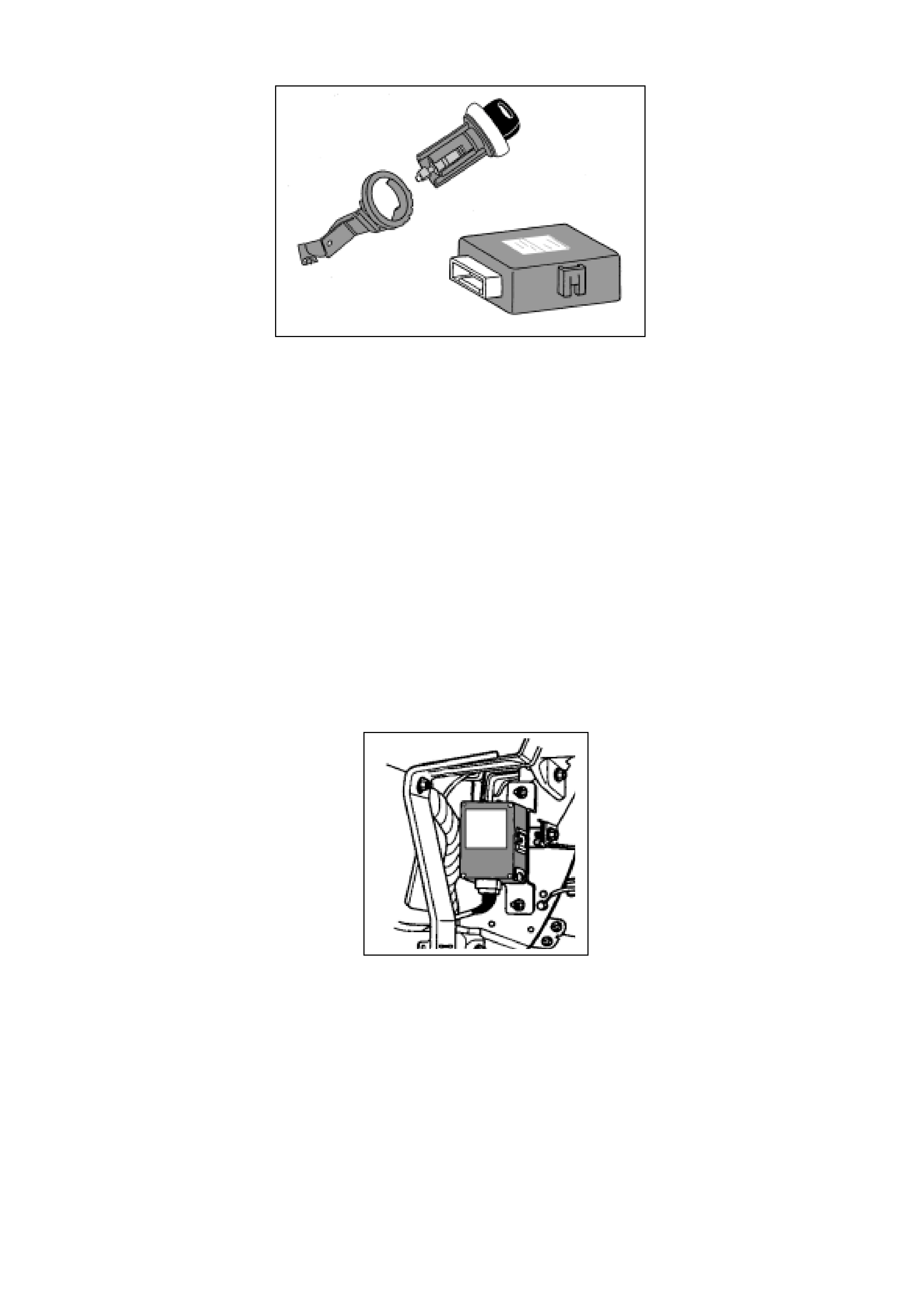
The main system components are:
• Ignition/transponder key
• Immobiliser antenna
• Immobiliser Contr ol Unit
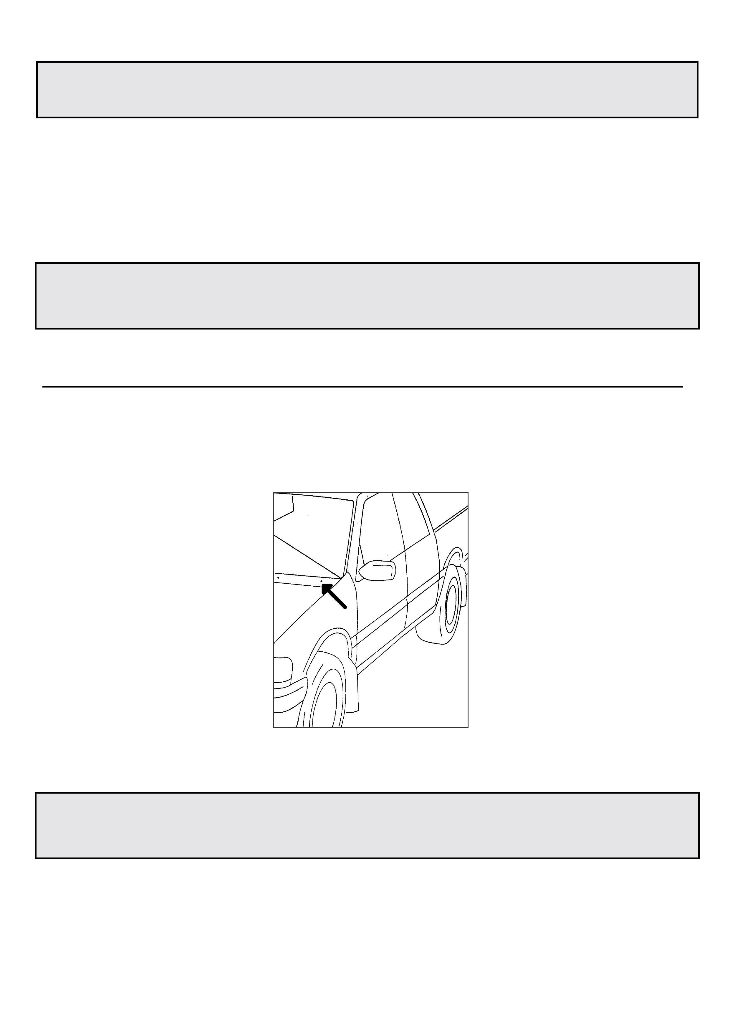
The antenna surrounds the ignition switch lock barrel, and is accessed by removing the steering column
shroud.
The Immobiliser Contr ol Unit is located to the right of the glovebox opening. Removing glovebox and the LH
lower instrument panel accesses the Immobiliser Cont r ol Unit. The Immobiliser Contr ol Unit and the PCM
are programmed to the vehicle via TECH2.
A non-contact radio frequency is used to transfer information between the key and the Immobiliser Control
Unit. Surrounding the ignition lock is a coil-type antenna, which is connected to the Immobiliser transceiver
and module. The antenna is designed to have a very limited range, ensuring that only the key inserted in t he
ignition can have its transponder code transferred. This excludes the possibility of interference from other
transponder keys in the vehicle.
W hen the ignition is turned ‘ON’, a radio frequency signal is sent from the antenna ring to the transponder in
the key. The transmitted energy powers the key’s integrated circuit, and the transponder transmits its code
back to the antenna ring. The transmitted code is received by the Immobiliser module and compared with
the stored codes. At the same time, the Powertrain Control Module (PCM) will req uest permission to start. If
the transponder and Immobiliser module codes match, the module will enable the Starter Motor relay and
send a coded signal to the PCM. Once the PCM recognizes the coded signal, it will enable the fuel and
circuits.
If the transmitted code from the transponder key is incorrect or the module receives no code, the starter
motor will not operate and the fuel and spark systems remain disabled.
If there is a malfunction – either incorrect transponder or no communication, the ‘CHECK ENGINE’ lamp in
the instrument cluster flashes and the relevant trouble code is stored in both the ICU and the PCM.
The module is initially programmed as standard with two transponder codes, corresponding to the two k eys
supplied with the vehicle. Should a key be lost, or an additional key required, uncoded keys are easily
programmed into the system with the aid of TECH-2. A maximum of 5 transponder codes can be stored in
the ICU.
System Programming
Programming of the Immobiliser system is perform ed with TECH- 2 when:
• The Immobiliser Contr ol Unit is replaced.
• The Immobiliser Contr ol Unit is reset.
• The PCM is replaced.
• Additional ignit ion keys ar e required.
• An ignition key has been lost.
CEL
VSS
STARTER
RELAY
GND B+ IGN
INJECTORS
IGNITION
VSS / CODE
START STATUS
PCM
POWER
CODE ICU
DLC
Pin #7

To enable the completion of the programming sequence, the technician should have obtained:
• The Vehicle Identification Number.
• The vehicle security code.
• The mechanical key number.
• Permission from TIS.
Security Data
The following codes/data are stored in the ICU reference memory during vehicle production:
• The Vehicle Identification Number.
• The vehicle security code.
• The mechanical key number.
• Engine type
• Transponder code/s
The security code cannot be deleted or altered with TECH-2. The transponder code/s and engine type are
processed internally only and are not displayed on TECH-2. The Vehicle Identification Number and
mechanical key number are stored as further information for vehicle identification and can be displayed on
TECH-2.
Security Code
The 4-digit security code prevents unauthorized programming and access to the data in the ICU via TECH-
2. The security code is programmed into the ICU.
Program Security Code
New Immobiliser Control Units do not contain a programmed security code. If the ICU is replaced, the
security code for that vehicle must be obtained, and then programmed into the ICU with TECH-2.
Replacement of the Immobiliser Control Unit
Due to the complex nature of the coded signals transmitted between the key and the ICU, it is necessary t o
replace both existing ignition keys when the ICU is replaced.
Resetting of the Immobiliser Control Unit
Resetting of the ICU may necessitate replacement of either of both existing ignition keys. This situation is
most likely to occur if the ICU is swapped from one vehicle to another.
Replacement of the PCM
Once programmed to the vehicle Immobiliser system, the PCM cannot be removed and used in another
vehicle. The is no PCM reset procedure available at this point in time – the Service Programming System
(SPS) required for r esett ing a PCM does not apply to current Jackaroo and Monterey.

Loss of a Transponder Key
If a transponder key is lost, all transponder codes in the Immobiliser Control Unit must be erased to prevent
unauthorised use. This will ensure that, whilst the ‘lost’ key will allow access to the vehicle, it cannot be
used to start the vehicle.
After erasing all existing codes, the transponder codes of the remaining keys and t he new transponder key
can be programmed.
NOTE:
Programming Approval must be obtained from TIS, using the ‘’Enable Programming” option, before either
control unit or transponder key programming is performed.
Once Programming Approval has been obtained, TECH-2 will allow five programming operations. Once all
five programming operations have been used, Programming Approval will then have to be obtained again.
If the five programming operat ions are not used within two days, they will be cleared f r om TECH-2, r equiring
further Programming Approval to be obtained.
10
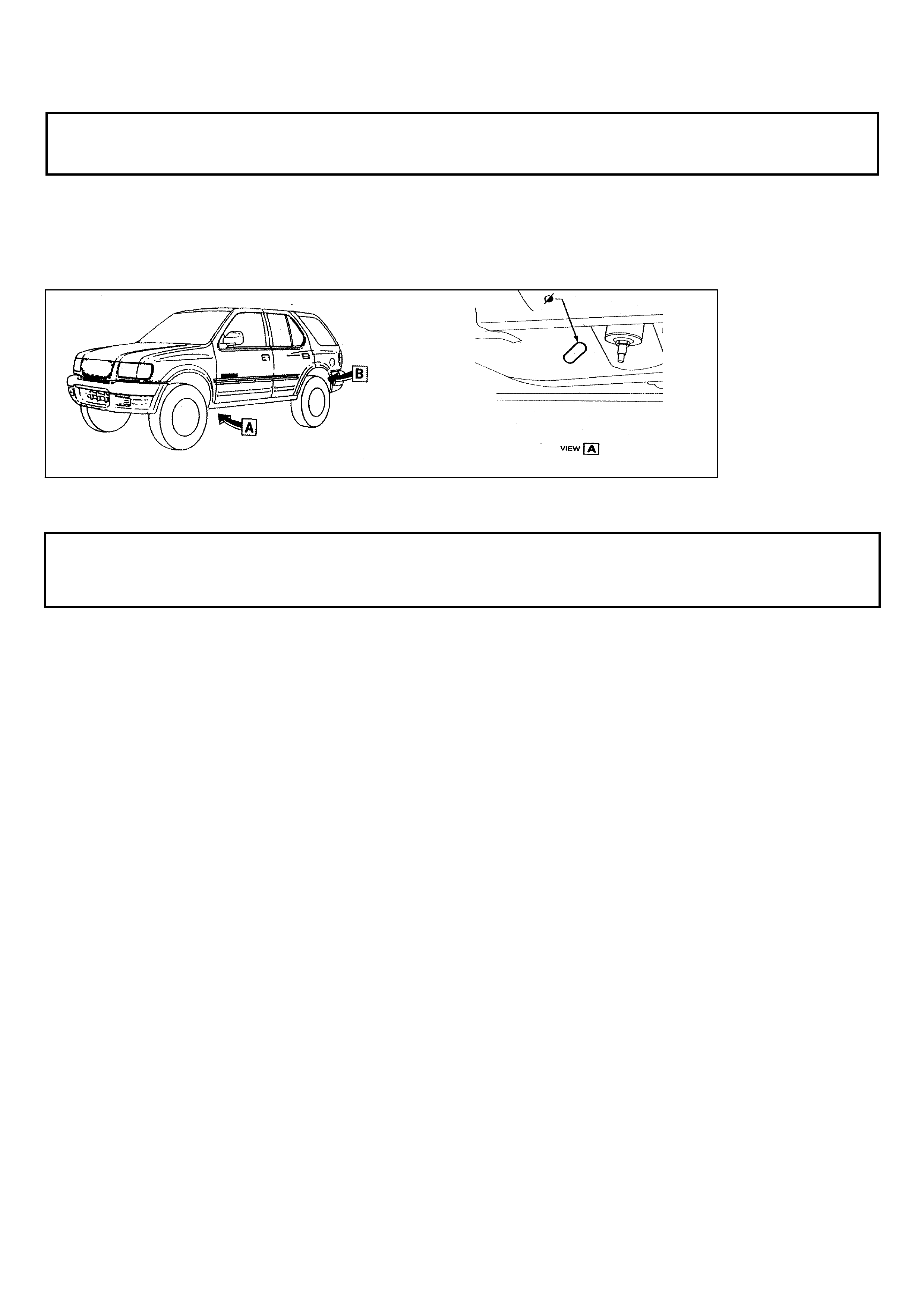
CHASSIS PLUGS (April 1999)
FRONTERA GROUP 1
The 1999 model Frontera has four chassis holes that are used as tie down points during shipment.
I – GM request that these holes be filled with plugs that are supplied in the glovebox (ref attached
drawing)
FUEL FILLER (April 1999)
RODEO CREW C AB GROUP 8
In instances where customers complain that a petrol engine Rodeo crew cab vehicle is difficult to
fuel or is blowing back th rough the filler neck, improvement can be achieved by replacing the filler
neck and hose.
The cause of the problem is the fuel filler neck / ho se combination not allo wing sufficient flow to
the tank
I–GM have relea sed a modified hose to be used in con junction with a space cab filler neck to
rectify the situation. Please refer to details below for the special labor operation number and
standard time.
Hose part number: 92074583
Filler neck part number: 8971676480
Labor operation number: L000184
Standard time: 0:9 h
11
S
y
stem
(w) 1998
F0: Powertrain
F1: Chassis
F2: Body
(w) 1999
(w) 1999
(w) 1999
(w) 1999
(w) 1999
Vehicle
Select one of the followin
g
Bod
y
Immobiliser
Airba
g
Ant i Theft Warning
Other
(w) 1999
(w) 1999
Immobiliser
Bod
y
F0: Dia
g
nost ic Trouble
F1: Data Dis
p
la
y
F2: Snapshot
F3: Actuator Tests
F4: Additional Functions
F5: Pro
g
rammin
g
(w) 1999
(w) 1999
JACKAROO IMMOBILISER (May 1999)
JACKAROO GROUP 12
In response to a high level of inquiries regarding the process involved to program an additional
ignition key to a current model Jackaroo, a step by step outline has been produced that shows the
tech 2 screen as it will appear as you move through the program.
NOTE: To code a new ignition key, a four-digit security number is required refer step 6.
The security number is obtained from TAS using the form attached to dealer
letter 8/98. It would be advisable to obtain this number before coding the key.
Step 1) Connect tech 2 to vehicle
Select diagnostics, select the vehicle as required, e.g.
1998 Jackaroo you will then see the screen as
displayed in picture 1.You must then select body.
Picture 1
Step 2)
Select immob iliser
Refer picture 2
Step 3)
Select programming
Refer picture 3
Picture 2 Picture 3

12
Step 4)
Select program
transponder keys.
Refer picture 4
Step 5)
You will see the screen
as in picture 4. You will
then need TIS approval
before pressing confirm.
Picture 4 Picture 5
Step 6)
Enter four digit security
number obtained using
the form attached to dealer
letter 8/98.
Refer picture 6
Step 7)
Insert new key
And c onfirm.
Refer picture 7
Picture 6 Picture 7
Pro
g
rammin
g
F0: Program Immobiliser
Function
F1: Program Transponder-
keys
F2: Program mechanical
Key Number
(w) 199 Jackar
) 1999
(w) 1999
(w) 1999
(w) 1999
Pro
g
ram
(w) 1999 Jackaroo
Electronic Sy stem:
Immobiliser
F2: Body
Please get programming
approval from
TIS!
(
(w) 1999
Confirm
Program
Immobiliser
Function
(W) 1998 Jackaroo
Electronic Sy stem:
Immobiliser
Security Code
0 0 0 0
(w) 1999
(Press ENTER key to
continue
Program
Transponder-
(W) 1998 Jackaroo
Electronic Sy stem:
Immobiliser
Insert Non-Programmed
Transponder Key
Confirm

13
Step 8)
You will see the screen
As shown in picture 8.
Tech 2 will request you
turn the ignition on, then off.
Step 9)
At completion of the
Programming a final screen
will appear asking if more
keys are to be coded.
Refer picture 9.
Picture 8 Picture 9
(w) 1999 Jackaroo
(w) 1999 Jackaroo
Pro
g
ram
(W) 1998 Jackaroo
Electronic Sy stem:
Immobiliser
Programming Transponder
Key
(w) 1999
Pro
g
ram
(W) 1998 Jackaroo
Electronic Sy stem:
Immobiliser
Program more Transponder
Keys ?
YES NO
HOLDEN SERVICE TECHLINE _________________________________________________________ JUNE 1999
22
AIR CONDITIONING INFORMATION
1999 FRONTERA GROUP 2
1999 model Frontera three door and five door vehicles do not have air conditioner refrigerant
sticker s fitted in the engine bay area.
For your infor mation the relevant details are:
CHARGE : 0. 65 kg HFC – 134a
LUBRICANT : 150 cc - 200PG
More detailed information on refrigerant recovery / recharge can be found in the relevant
section of t he workshop m anual
( Section 1A, page 49 – 53 )
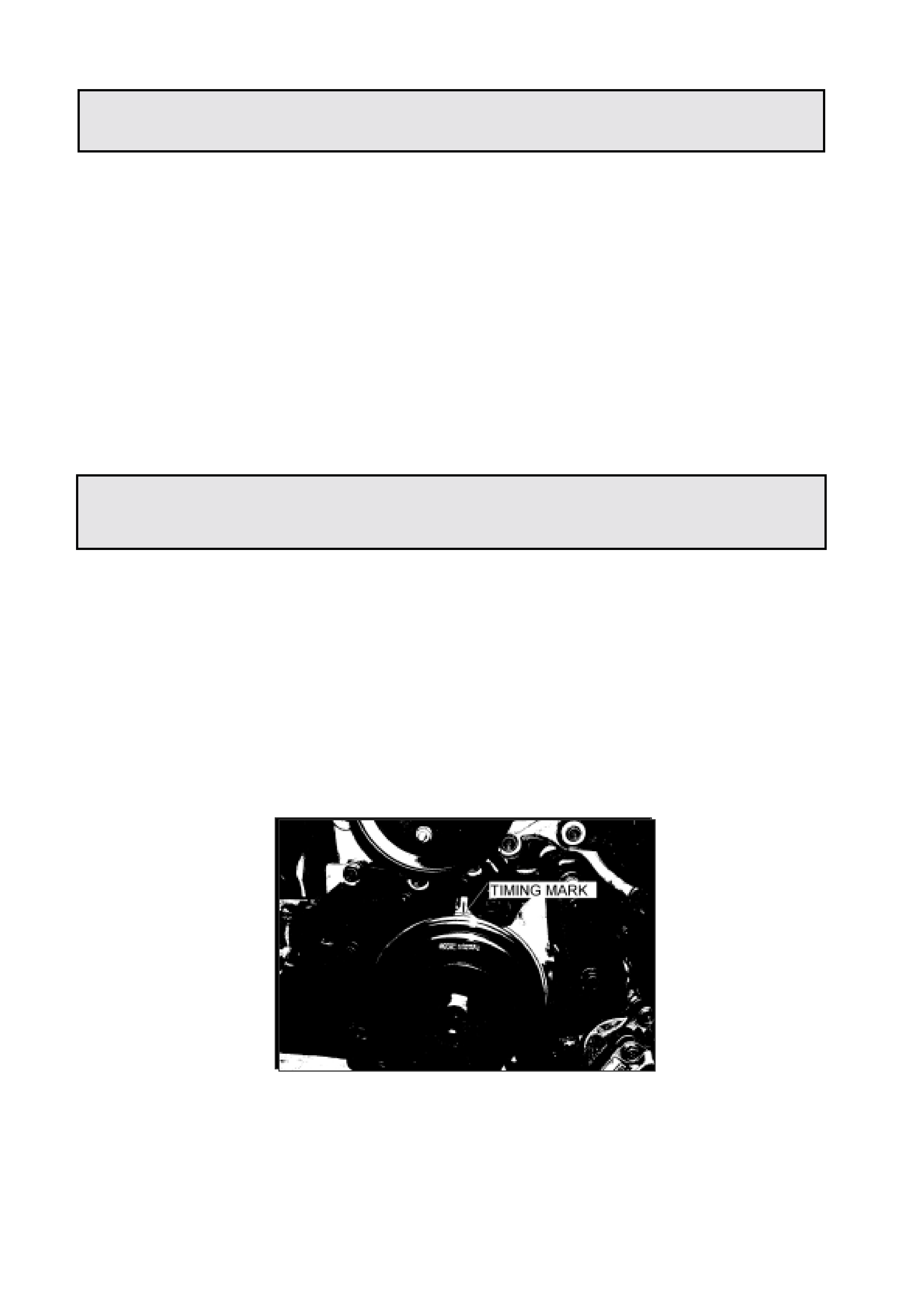
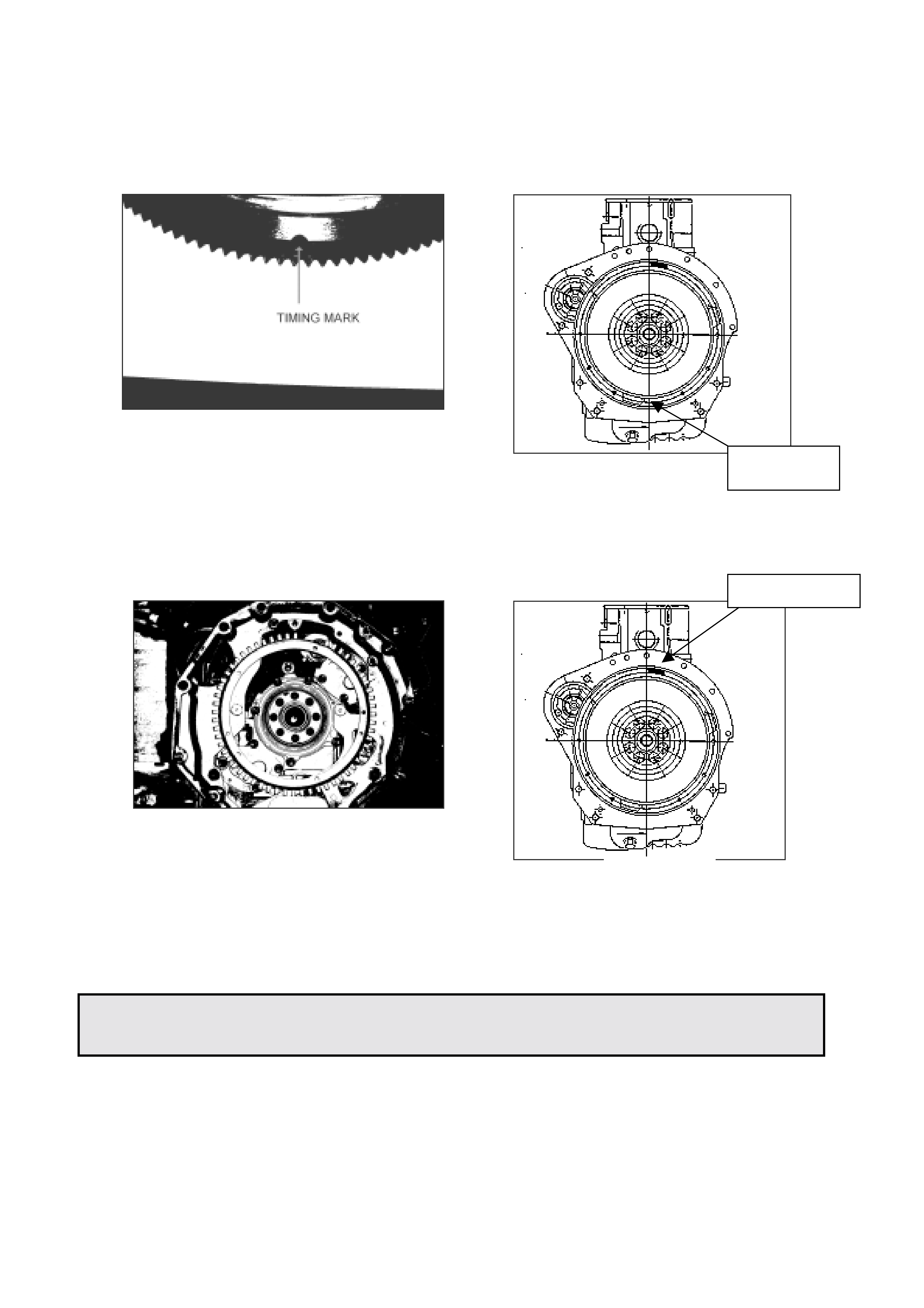
4JX1 FLYWHEEL SETUP PROCEEDURE
JACKAROO GROUP 6A
When removing the flywheel on a 4JX1 engine, the flywheel should be marked to ensure
installation in the same position. The position of the flywheel in relation to the crankshaft is
critical for engine operation as the crankshaft position sensor reads off the toothed wheel
attached to the flywheel.
In instances where assembly is required without reference marks the following procedure can
be used.
1. Align crankshaft pulley notch with mark on timing case t o obtain T.D.C.
(ref drawing 1)
DRAWING 1
HOLDEN SERVICE TECHLINE _________________________________________________________ JUNE 1999
23
2. Fit f lywheel to crankshaft taking note that :
A) Timing mark is pointing downward (ref dr awing 2 & 2A ).
B) Crank shaft sensor t oot hed wheel is in correct position
(ref drawing 3 & 3a).
4JX1 ENGINE OIL SPECIFICATION
JACKAROO GROUP 6A
Due to the diesel injection system used in t he curr ent Jack aroo diesel 4JX 1, eng ine oil is crit ical
to the correct operation of the engine. Incorrect spec engine oil may dramatically increase
cranking times, cause r ough idle, and in extrem e conditions cause a no start / st alling sit uation.
The engine oil specification for the Jackaroo diesel 4JX1 engine is 15W/40 CG-4, however in
extreme cold operating conditions e.g. alpine areas, a lower cold viscosity rating is
recommended e. g. 5W/40.
TIMING MARK
POSITION
MISSING TEETH
DRAWING 2
DRAWING 2A
DRAWING 3A
DRAWING 3
23
4JX1 INJECTOR CALIBRATION (June 1999)
JACKAROO GROUP 6M
The 4JX1 diesel engine in the 1998 model Jackaroo has i nject ors that are classifi ed i nt o 9 groups
according to flow rate. The ECM is calibrated to the injectors that are fitted to the engine using
Tech 2.
Injector calibration is carried out at production, but will need to be checked at pre delivery and
after some service repairs. e.g. control unit replacement, injector replacement, etc.
Incorrect injector cal i brat ion may cause unstable idle, engine vibration or excessive smoke.
When performing inj ector calibration difficulty may be experienced identif ying the injector calibration group.
The workshop manual indicates that identification is determ ined by markings on the injector. This is not
the case. T he only met hod for identification is to utilise t he injector identification stick er, situated on the
noise insulator cover that is above the rocker cover.
INJECTOR IDENTIFICATION STICKER
ENG. NO 489476 4JX1
#1 82395420 #2 83395420
#3 83365520 #4 59395920
RP SENSOR 7565
The number s on t he ident ification sticker are product ion numbers (not part num ber s) used to identif y
individual injectors. T he 5th and 6th digits of t he pr oduct ion num ber ar e used to classify injectors for
calibration. eg.
#1 82395420
CALIBRATION NUMBER ( 54 )
INJECTOR NUMBER (# 1)
The calibrat ion number is used in conjunction with the following chart.
A1 20 – 26 B1 40 – 46 C1 61 – 67
A2 27 – 33 B2 47 – 53 C2 68 – 74
A3 34 - 39 B3 54 - 60 C3 75 – 80
For example: Inj ect or number 1 has a calibration number 54. Number 54 corr esponds to a B3.
Once the injector calibration number has been est ablished and injector categ or y deter m ined, the
calibration procedure in the relevant workshop manual (sect ion 6E )
can be followed.

1
INJECTION TIMING ADJUSTMENT (July 1999)
RODEO with 4JB1T
(GRO UP 6M)
Current model Rodeo vehicles equipped with the 4JB1-T engine have six timing marks on the
crankshaft pulley as opposed to the four pictured in the workshop manual.
The following diagram should be used to update the current manual by inserting the extra two
marks in the relevant picture (Section 6A, Page 28) in a permanent marker.
Once workshop manuals have been updated, checks \ adjustment of the pump timing should be
done as per the workshop manual procedure.
0 4 10 12 14 16
REVISED ENGINE CRANKS BUT WILL NOT RUN PROCEDURE (July 1999)
JACKAROO with 4JX1T
(GRO UP 6M)
Engine Cranks But Will Not Run
Step Action Value Yes No
1 Was the “on board diagnostic (OBD)
system check” performed? - Go to step 2 Go to OBD
system check
2 Check the 15A stop light fuse and in the
engine compartment fuse panel the 15A
and 50A ECM fuses. Was a fu se blown?
- Go to step 3 Go to step 4
3 Check for a short to ground and replace
the fuse. Is action complete ? - Verify repair -
4 Is fuel tank empty? - Fill fuel tank Go to step 5
5 Is the right fuel being used? - Go to step 6 Replace fuel
6 Is the right engine oil being used? - Go to step 7 Replace
engine oil
7 Using the tech 2.
Is DTC P0192 or P0193 set? (check rail
pressure system)(Must have 4Mpa min.)
- Go to DTC
P0192 or
P0193
Go to step 8
8 Using the tech 2.
Is DTC P0201 - P0204 set? (check
injector circuit fault)
-Go TO DTC
P0201-
P0204
Go to step 9

2
Step Action Value Yes No
9 Using the tech 2.
Is DTC P1657 set? (check ECM main
relay)
-Go to DTC
P1657 Go to step 10
10 Refer to Engine Mechanical Diagnosis to
diagnose the following conditions:
• Faulty camshaft drive belts
• Leaking or sticky valves or rings
• Excessive valve deposits
• Weak valve springs
• Incorrect valve timing
• Leaking head gasket
Is the action complete?
- Verify repair Go to step 11
11 Observe the engine speed data display
on the tech 2 while cranking the engine.
Is the engine RPM indicated?
- Go to step
23 Go to step 17
12 Using a digital multi-meter set on AC
volts, connect between ECM J3-5 and
one of the injector driver circuits and
crank engine.
Is there a voltage of approx. 4 volts?
- Go to step
13 Go to step 15
13 Using a digital multi-meter set on ohms,
check for a short to ground in the injector
driver circuits.
- Go to step
14 Go to step 16
14 Locate and repair the short to ground in
the injector driver circuit.
Is the action complete?
- Verify repair -
15 check for an open injector driver circuit.
Is the action complete? - Verify repair Go to step 16
16 Replace the ECM
Is the action complete? - Verify repair -
17 1. Disconnect the CKP sensor harness
2. Turn ignition on.
3. With a test lamp to ground, probe the
sensor
harness ignition feed terminal.
Did the test lamp illuminate ?
- Go to step
19 Go to step 18
18 Check the ignition feed wire between the
sensor and the ECM for a short to ground
or open circuit.
Is the action complete?
- Verify repair -
19 Ignition on.
At the CKP harness connector, connect a
test light between the ignition and ground
terminals.
Did the light illuminate?
- Go to step
21 Go to step 20
20 Check the sensor ground circuit for an
open or short to voltage.
Is the action complete?
-Verify
Repair -

3
Step Action Value Yes No
21 Check the signal circuit between the
sensor and the ECM for a short to
ground, short to voltage or an open
circuit.
Was a problem found?
-Verify
Repair Go to step 22
22 Replace the CKP sensor.
Is the action complete? -Verify
Repair Go to step 23
23 1. Disconnect the CMP sensor harness
2. Turn ignition on.
3. With a test lamp to ground, probe the
sensor
harness ignition feed terminal.
Did the test lamp illuminate ?
- Go to step
25 Go to step 24
24 Check the ignition feed wire between the
sensor and the ECM for a short to ground
or open circuit.
Is the action complete?
-Verify
Repair -
25 Ignition on.
At the CMP harness connector, connect a
test light between the ignition and ground
terminals.
Did the light illuminate?
- Go to step
27 Go to step 26
26 Check the sensor ground circuit for an
open or short to voltage.
Is the action complete?
-Verify
Repair -
27 Check the signal circuit between the
sensor and the ECM for a short to
ground, short to voltage or an open
circuit.
Was a problem found?
-Verify
Repair Go to step 28
28 Replace the CMP sensor.
Is the action complete? -Verify
Repair -

4JX1- TC MODIFIED TURBOCHARGER AND HOSE (September 1999)
JACKAROO
(GRO UP 6A)
Jackaroo vehicles fitted with the diesel 4JX1 engine may exhibit a condition where the intake pipe
between the turbocharger and intercooler m ay continually blow off under boost pressure.
I-GM has released a modified turbocharger, with increased outlet duct length and an improved hose
lip, to be used in conjunction with a modif ied hose that indicates hose clamp locat ion, t o overcome the
above complaint. Refer to All Dealer Letter IGM 25/99 f or det ailed fitting inst ructions.
Hose part number : 8972052041
Turbo part number: 8971371098

SERVICE SCHEDULE REVISION (October 1999)
UES FRONTERA
(GRO UP 0B)
I-GM wish to advise technicians of two revisions to the service schedule of the current model UES
Frontera from the schedule shown in Chapter 12, Page 6 of t he owners handbook .
1) Manual transm ission and transf er case oil is no longer to be r eplaced at 10000 k m as indicated in
the service schedule. The f irst manual t ransmission and transf er case oil chang e is now at 40000
km, and thereaft er as indicated in the service schedule.
2) Automatic transm ission and transfer case oil is no longer t o be replaced at 10000 k m as indicated
in the service schedule. The first automatic transmission and transfer case oil change is now at
40000 km, and thereaft er as indicated in the service schedule.
The above revisions will apply for all 1999 UES m odel vehicles that have not already had a 10000 k m
service.
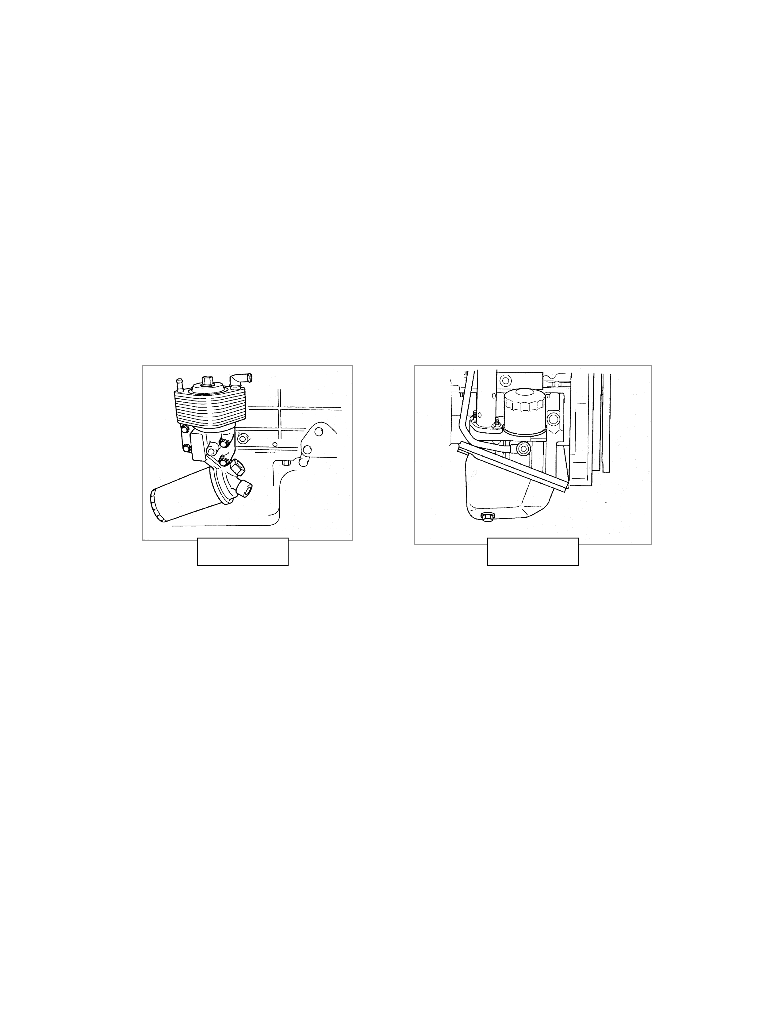
4JX1 - TC JACKAROO DIESEL SECOND OIL FILTER (September 1999)
JACKAROO
(GRO UP 6A)
The 4JX1- TC diesel engine as f it ted to the 1998/ 1999 model Jackaroo vehicles is equipped with two
oil filt ers.
The service f ilter is mounted on the dr ivers side of the engine and should be changed as per the
service schedule. ( refer picture A )
The second filter is mounted on t he passenger side of the engine and is marked “2nd O/F”.( refer
picture B) The second filter shoul d not be changed in ser vice, except in t he event of engine rebuild
or contaminat ion. This is a low volume filter t hat protects t he inj ection system.
PICTURE A PICTURE B
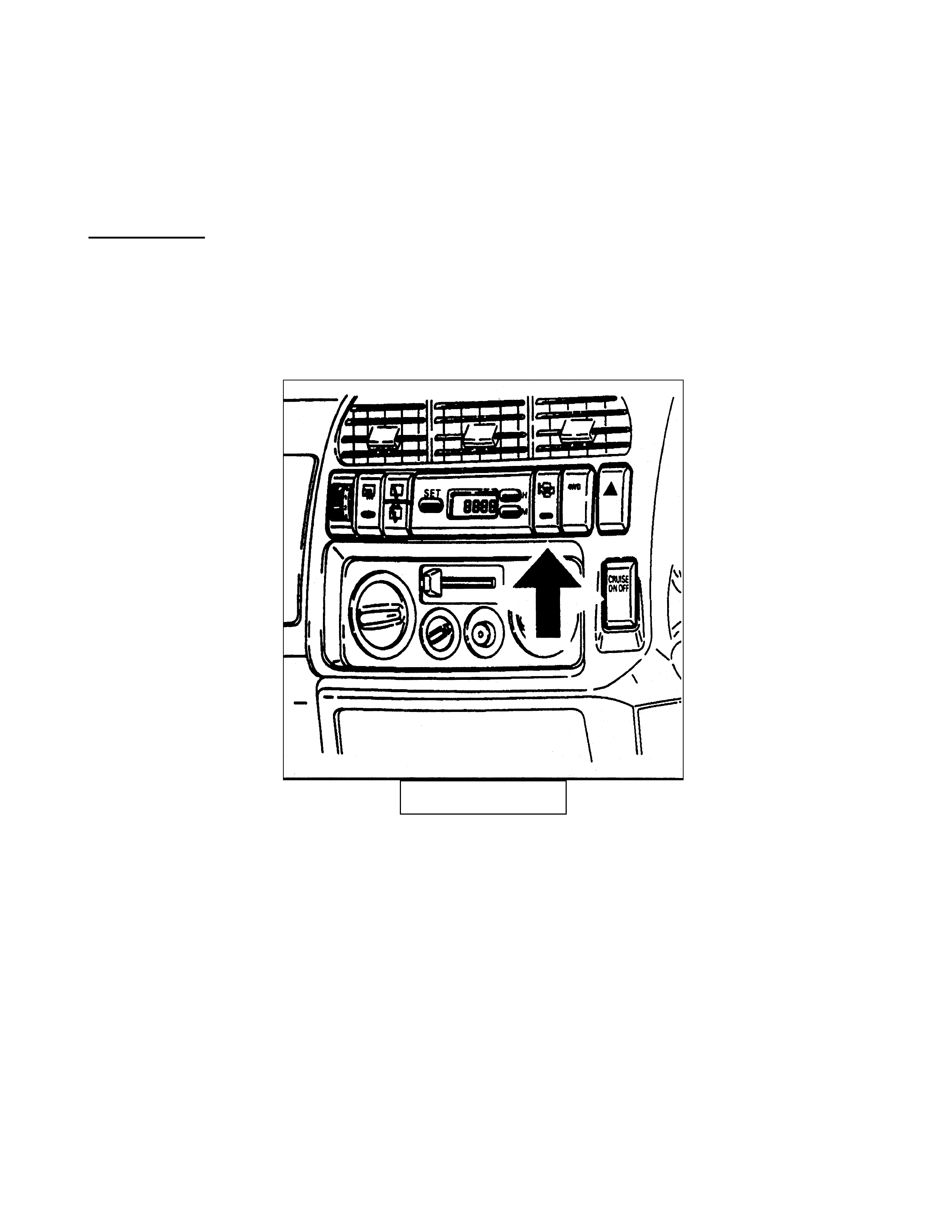
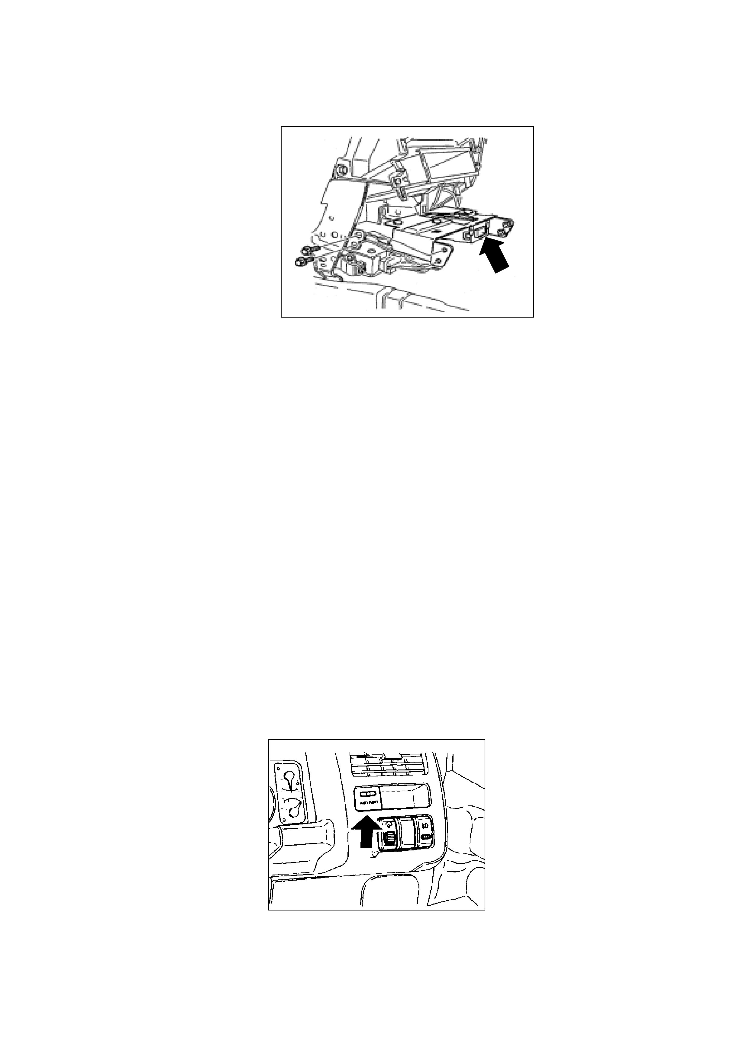
4JX1 - TC QUICK WARM UP SYSTEM (September 1999)
JACKAROO
(GRO UP 6Y)
DESCRIPTION
The 4JX1 – TC is fitted with a quick warm up system that may be selected by depressing a dash
mounted switch.
The function of the quick warm up system is to decrease engine warm up time in cold conditions by
restrict ing air flow throug h t he engine.
DASH SWITCH
To rest rict air flow, the ECU cont rols a butterf ly located on the exhaust engine pipe and the throttle
stepper mot or on the inlet manif old.
If the dash switch is depressed the ECM will activate / de-activate the system automatically as
engine tem per at ure conditions dictate.
When the system is activated the light located on the dash switch will illuminate, when the engine
temperature rises above 80C the ECM will override the switch to de-activate the system and the
light. The system contains an ambient temperature sensor located behind the grill that will override
the switch de-activating t he system and the light if t he ambient tem perature is above 15C. If coolant
temperature is above 50C on start up the ECM will override the dash switch and de-activate the
system.
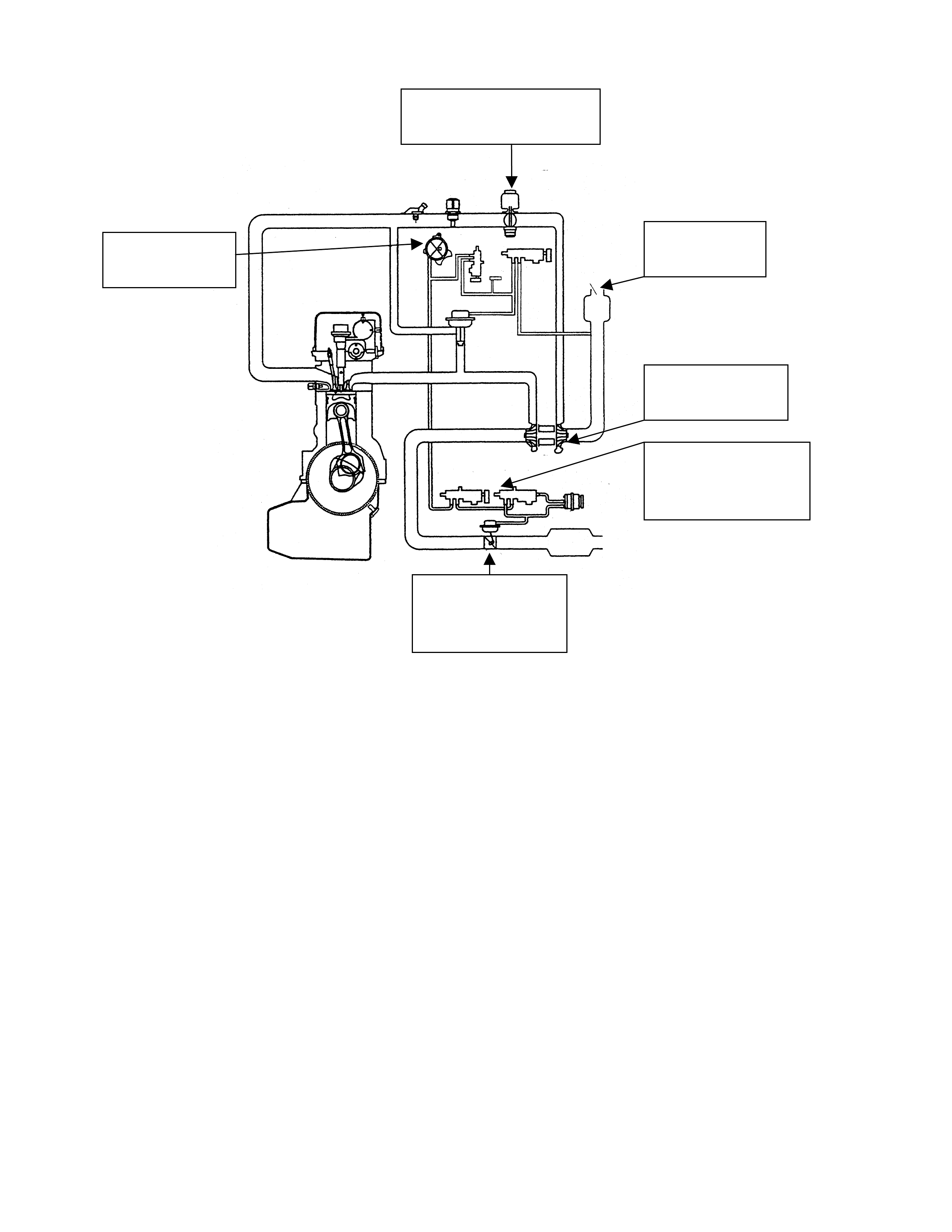
INTAKE THROTTLE
STEPPER MOTOR
VACUUM
PUMP
AIR
CLEANER
EXHAUST
BUTTERFLY
TURBO
EXHAUST
BUTTERFLY
VALVES

FLATSPOTTING OF TYRES (September 1999)
ISUZU ALL MODELS
(GROUP10)
Flat spotting of tyres caused during vehicle storage and shipping is an ongoing problem in Australia.
This phenomenon has been noted where vehicles have been tightly secured and shipped over large
distances, and is further exacerbated by tight er strapping and long term stor age.
Flat spotting of tyres alter s the r ide and handling char acterist ics; it mak es the vehicle most unpleasant
to drive and affects customer satisfaction as a result . Under inflation exacerbates the problem.
Dealers are advised not to rebalance tyres that are suspected of having flat spots, instead
tyres should be inflated to the recommended specifications and the flat spot driven out of the
tyre. This could take in excess of 100km or more.
If t he pr oblem still persists after the above action please contact IGM TAS.

REFRIGERANT CHARGE QUANTITY (November 1999)
TF RODEO
(GRO UP 2)
Recent Air International in house charge determination testing has revealed an error in the
quantit y of refr igerant recommended for t he Rodeo V6 4x2, 4x4 models.
The original specif ication as nominated on the A/C label and f itting instruct ions was 900 + or – 25
grams, we now realise that this should be 730 + or – 25 grams.
All dealers should alter their fitting instructions to reflect the new value. The specification label
supplied with new kits will also be altered accordingly.
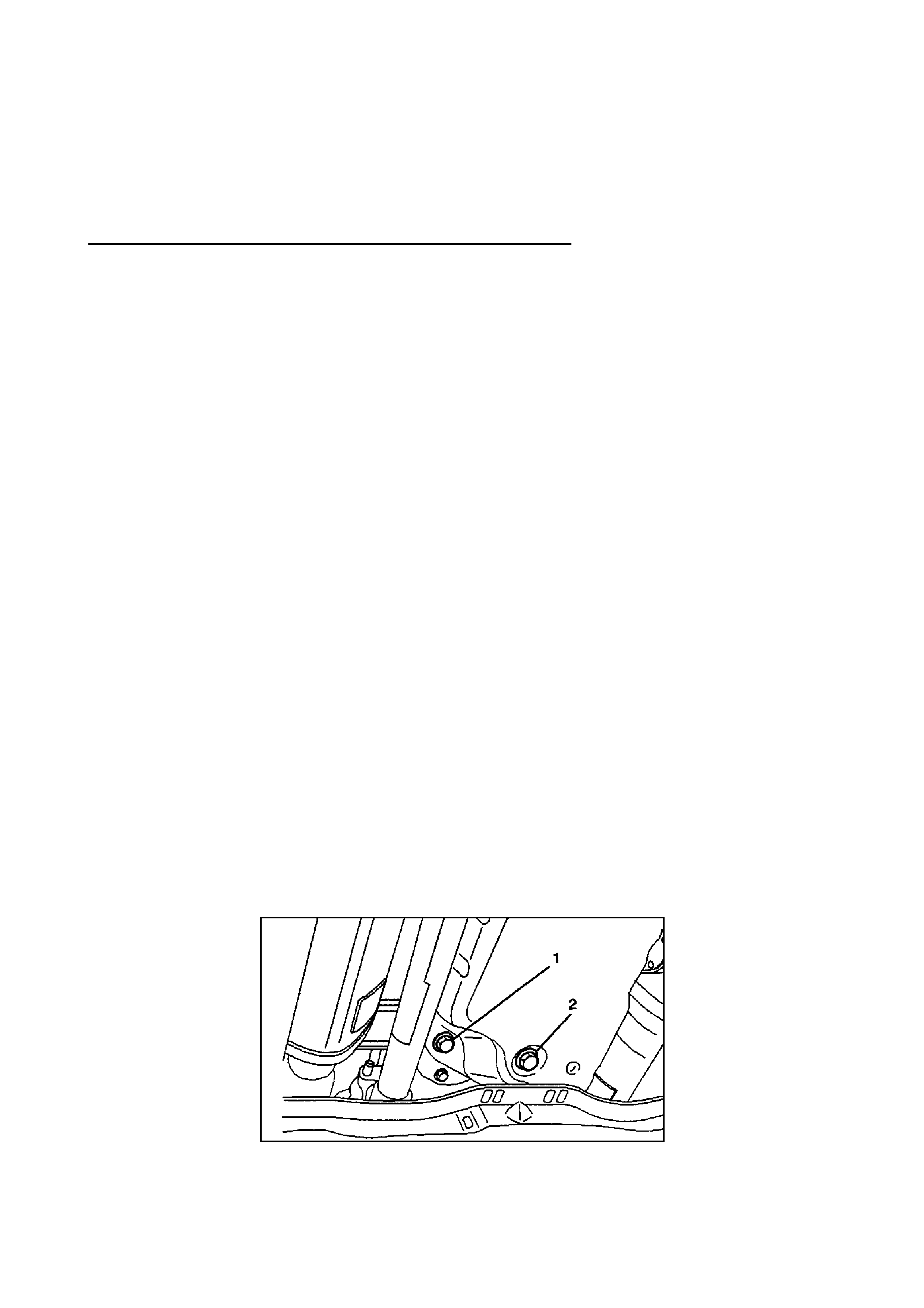
4L30E AUTOMATIC TRANSMISSION FLUID LEVEL CHECK PROCEDURE (November 1999)
JACKAROO, RODEO, FRONTERA
(GRO UP 7B)
CHECKING TRANSMISSI O N FLUID LEVEL AND CONDITION
Checking fluid level and condition (colour and odour) at regular intervals will provide early
diagnosis inf ormation about the transmission. This inf ormation may be used to correct a condition
that, if not detect ed ear ly, could r esult in major transmission repairs.
IMPORTANT: When new, automatic transmission fluid is red in colour. As the vehicle is driven, the
transmission fluid will begin to look darker in colour. The colour may eventually appear light brown.
A dark brown colour with burnt odour may indicate excessive fluid deterioration and signal a need
for fluid change.
FLUID LEVEL
When adding or changing fluid, use only DEXRON III. Refer to Maintenance and Lubrication in the
relevant owners manual for ser vice inter vals.
CAUTION: DO NOT OVERFILL.
Overfilling will cause foaming, loss of fluid, abnormal shifting and possible damage to the
transmission.
1. Park the vehicle on level ground and apply the parking brak e firmly.
2. Check fluid level with engine running at idle.
NOTE: Be sure that transmission fluid temperature is below 30° C (86° F).
3. Move the selector lever through all gear ranges.
4. Move the selector lever to "park.
5. Let eng ine idle for 3 minutes and open the overfill screw (REFER DRAWING A).
6. Add released tr ansm ission fluid until it flows out over the overfill screw opening.
7. Let engine idle until a fluid temperature between 32° C (90° F) and 57° C (135° F) is reached,
then close the overfill screw (1).
Torque: 38 Nm (3.9 kg.m128 lb f t )
NOTE: Check t r ansmission fluid temper at ure with scan tool.
Minimum fluid level 57° C (135° F) Maximum f luid level 32° C ( 90 ° F)
DRAWI NG A
1 – FILL PLUG 2 – DRAIN PLUG
CAUTION: Do not open overfill screw with engine stopped.

CAUTION: DO NOT CHECK FLUID LEVEL UNDER THESE CONDITIONS:
• Immediat ely after driving at sust ained highway speeds.
• In heavy city traffic during hot weather.
• If vehicle is towing a t r ailer .
If the vehicle has been operated under these conditions, shut the engine off and al low the
vehicle to"cool" f or ( 30) mi nut es. After the cool down period, restart vehicle and cont i nue
from step 2 above.

VALVE CLEARANCE SHIM CALCULATION (November 1999)
4JX1 JACKAROO
(GROUP 6A)
The following correction has been made to the valve clearance adjusting shim calculation
procedure for the 4JX1 engine.
Current Calculation
TA: T hickness of new adjuster
M: Valve clearance measurement
TO: Thickness of the removed adjuster
For Intake: TA=TO+(M+0.15) mm
For Exhaust: TA=T O + ( M+0.25) mm
Correct Calculation
TA: T hickness of new adjuster
M: Valve clearance measurement
TO: Thickness of the removed adjuster
For Intake: TA=TO+(M-0.15) mm
For Exhaust: TA=T O + ( M-0.25) m m
Workshop manuals should be corrected accordingly. The above information appears in Section
6A, page 64 of the 4JX1 workshop manual.
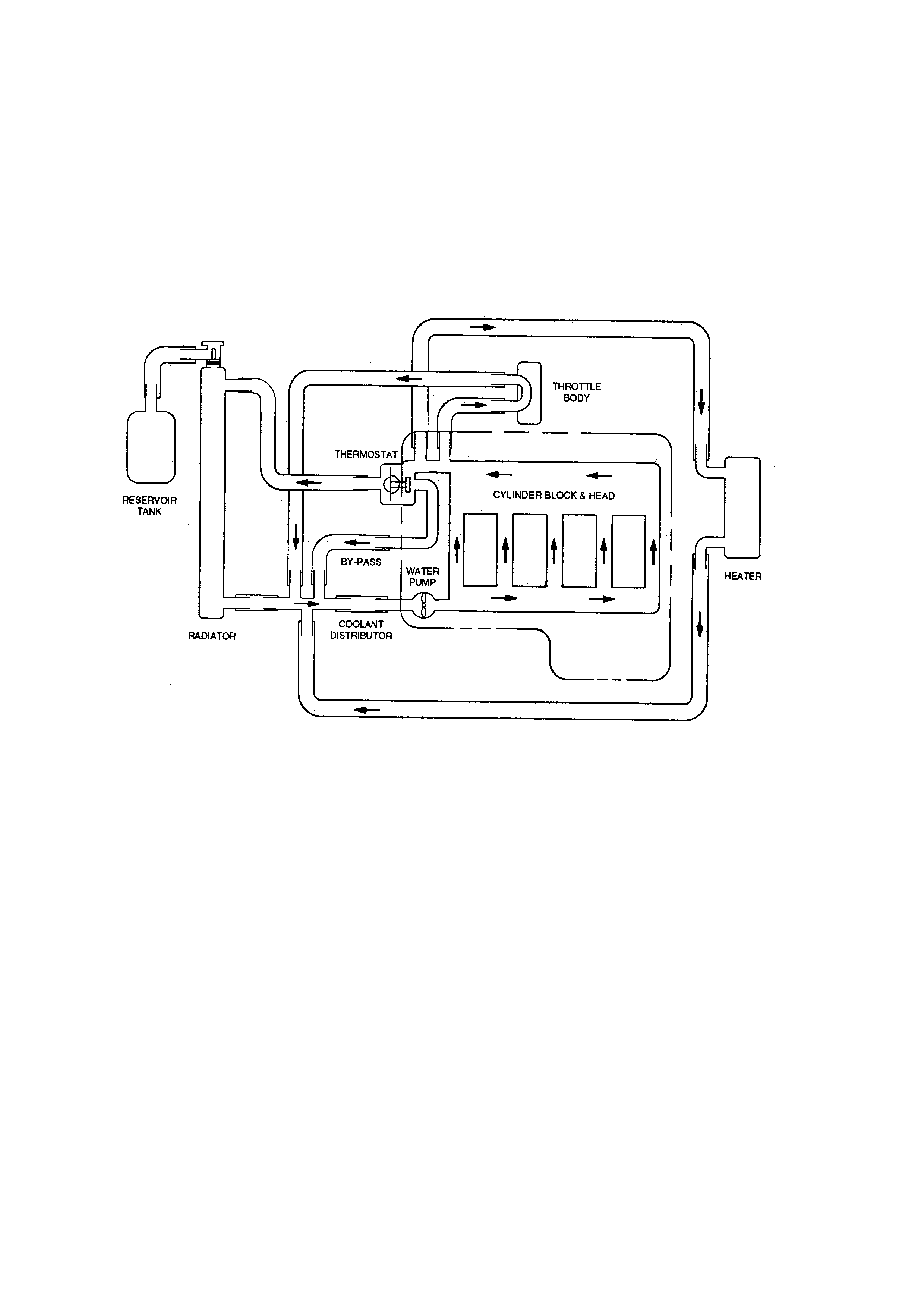
REVISION OF COOLING SYSTEM (November 1999)
2.2 TF RODEO
(GRO UP 6K)
The following revision has been made to the cooling system diagram for 2.2 (C22NE) engined
Rodeos.
Workshop manuals should be corrected accordingly. The above information appears in Section
6B, page 2 of the 1999 TF 2. 2 work shop m anual.