2
20
00
00
0
C
CA
AM
MP
PA
AI
IG
GN
N
B
BU
UL
LL
LE
ET
TI
IN
NS
S
© 2006 GM Holden LTD. A.B.N. 84 006 893 232
Service Department
A “HOLDEN” Product.
BRISBANE SYDNEY MELBOURNE ADELAIDE PERTH
For the latest and/or any missing Campaign Bulletins,
please refer to Holden Lionheart
1
PRODUCT CAMP AIGN BULLETIN
00-H-01
September 1, 2000
SUBJECT : SRS WARNING LAMP ACTIVATION
This bulletin announces t he initiation of a safety related campaign of a small number of model year
2000 built HSV, GTS series 300Kw output vehicles, in order to check the activation status of the
Supplementary Restr aint System (SRS) warning lamp.
DESCRIPTION O F DEFECT
Investigation has shown that a small number of vehicles in a specific batch may have been
released from the Vehicle Assembly Plant with the SRS warning lamp deactivated. It is important
to note that the deactivation of the SRS lamp does not prevent the SRS system from deploying,
however it would prevent the SRS warning light from illuminating should an SRS system
malf unct ion occur .
DETAILS OF AFFECTED VEHICLES
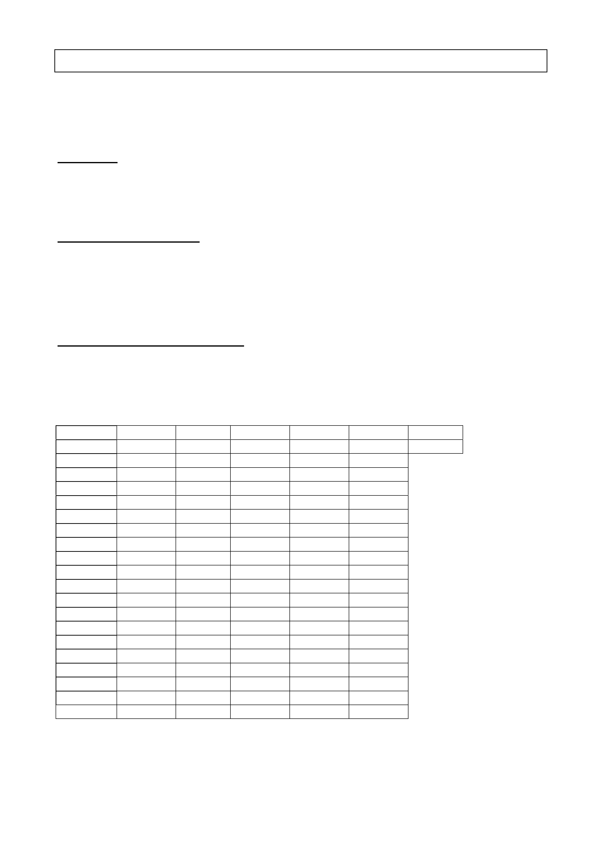
A total of one hundred and twenty eight (128) vehicles are af fected. These vehicles are identif ied
in Table 1 below:
List of Affected Vehicles
L536169 L561139 L565238 L574887 L579961 L588967 L606357
L547754 L561242 L565680 L575583 L580103 L589410 L607018
L547918 L561358 L565833 L575957 L580580 L589563
L551273 L561665 L566234 L576080 L580685 L589907
L551825 L561771 L566421 L576202 L581149 L590600
L553513 L561941 L566819 L576333 L581306 L591233
L559090 L562078 L567006 L576835 L599658 L591451
L559221 L562304 L567380 L576960 L582247 L591774
L559332 L562332 L567546 L577051 L582520 L591952
L559423 L562465 L568009 L597078 L582824 L592427
L559533 L562595 L568243 L577462 L582992 L593126
L559840 L562913 L568614 L577576 L583428 L593691
L559942 L563033 L599123 L577902 L583966 L594203
L560036 L563179 L569737 L578032 L584689 L594717
L560144 L563318 L570420 L578181 L585203 L594865
L560334 L563489 L570935 L578511 L585653 L595340
L560480 L598526 L571514 L578605 L585819 L602579
L560642 L563814 L572150 L578747 L586631 L602721
L560745 L563947 L572750 L579128 L587075 L603242
L561036 L564268 L573168 L579320 L587514 L604684
L597820 L565062 L574367 L579524 L588334 L605186
Table 1

2
OWNER NO TIFICATION
Each owner aff ected by this safety related campaign has been contacted by phone by a Holden
representat ive and provided details of the campaign. Your dealership has been nominated to
carry out the campaign rectif icat ion work and a booking date and tim e has been ar r anged.
Your co-operat ion and assist ance in complying with t he cust om er’s request via Holden CAS is
specifically req uested so that customer inconvenience is minimised and t he r equired action is
completed on all vehicles as quickly as possible.
DEALERSHIP ACTION REQUIRED
On presentat ion of the vehicle considered by the customer t o be affect ed by this campaign:
• Confir m that the vehicle is listed in Table 1.
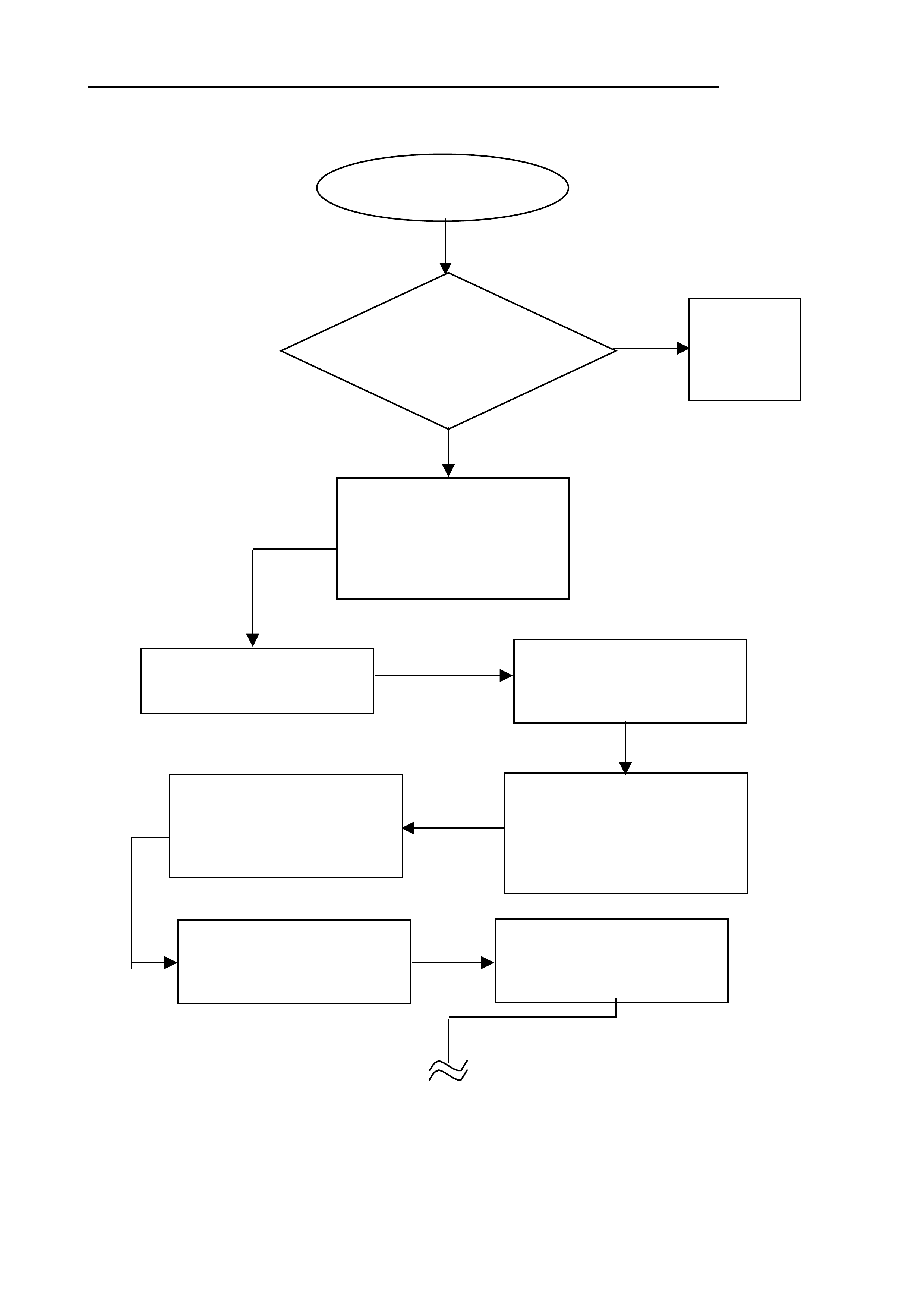
• Using TECH2, follow the flow chart (attachment A) to enable the SRS warning and perform a
funct ional check as per flow chart.
CAMPAIGN COMPLETION IDENTIFICATION
All campaigned vehicles must have a Campaign Completed identification label applied to the right
hand fr ont ‘A’ pillar, between the hinges, with details of the campaign, 00-H-01, dealership code
and date legibly entered on t he label with a perm anent ink pen.
Extra campaign ident ification labels are available free of charg e from:
Moore Business Systems
Facsimile: (03) 9270 8900
Attention: Mr. Bob Curry
Quote stock No. SD 28156 on a Moore Business Systems ‘packaged goods’ order form (or
facsim ile if not available) fo r a box of 100 labels.
WARRANTY CLAIM I NFO RMATIO N
On completion of campaign action, dealers are requested to immediately submit a w arranty
claim.
Description: Check and if appropriate program SRS warning lamp st atus to ‘Enabled’
Labour Operat ion No: T080801
Standard T ime: 0.7 Hours
Failure Code: 96
Case Type: 08
Please note that a 0. 5 hrs bonus is included in t he Standard T ime t o cover miscellaneous activities
associated with priority booking of customers.
Please ensure correct vehicle details are included when submitting warranty claim information as
per the norm al warranty process.
Warranty claim submission is used to update our record of campaign completion and determines
whether furt her cust omer contact is necessary to action all af fected vehicles.
Please ensure on completion of the campaign act ion t hat a warranty claim is submitted prompt ly.
Should you require further information or clarification on the above, then please call Oliver
Mitrovski on telephone number ( 03) 9647 7619.
Joachim Burandt
General Service Manager
3
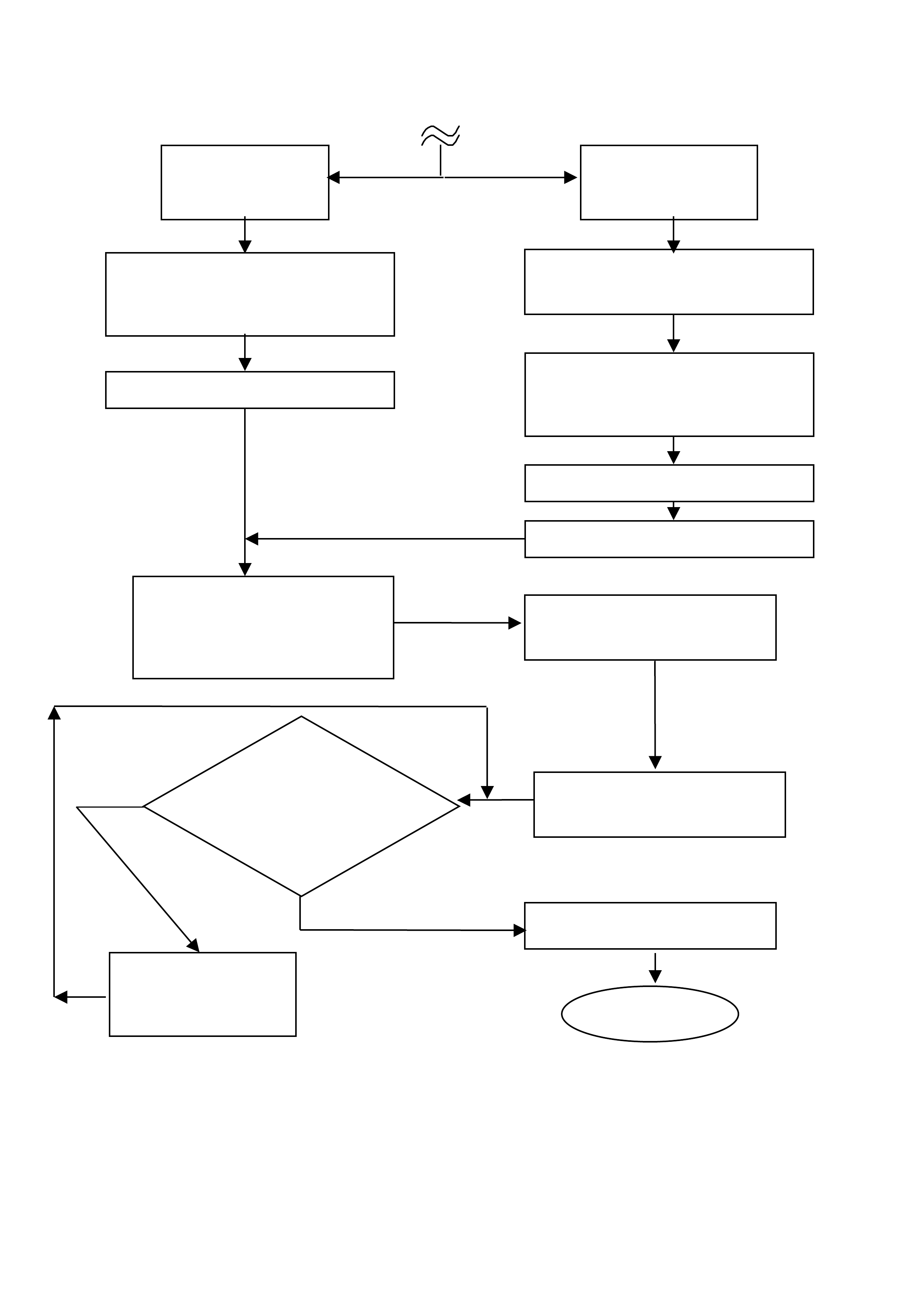
Attachment (A) DETAILED TECHNICAL INSTRUCTIO NS CAMPAIGN 00-H-01
Yes
Connect tech 2 to vehicle.
Refer to section 0C - Tech
2 of the commodore
service information in S.I.P
No further
action is
required
From the main menu
select F0:
Does vehicle fit a tag
number specified in
this product campaign
bulletin
No
From the system
menu select F3:
From the vehicle
identification screen
select ‘Instrument’
START
From the body menu select:
DTC check
* Turn ignition ON and press
‘Confirm’ soft key
If code appears, use the
appropriate diagnostic
procedure in SIP (Service
Information Package) to fix.
Return to the system
menu select F3:
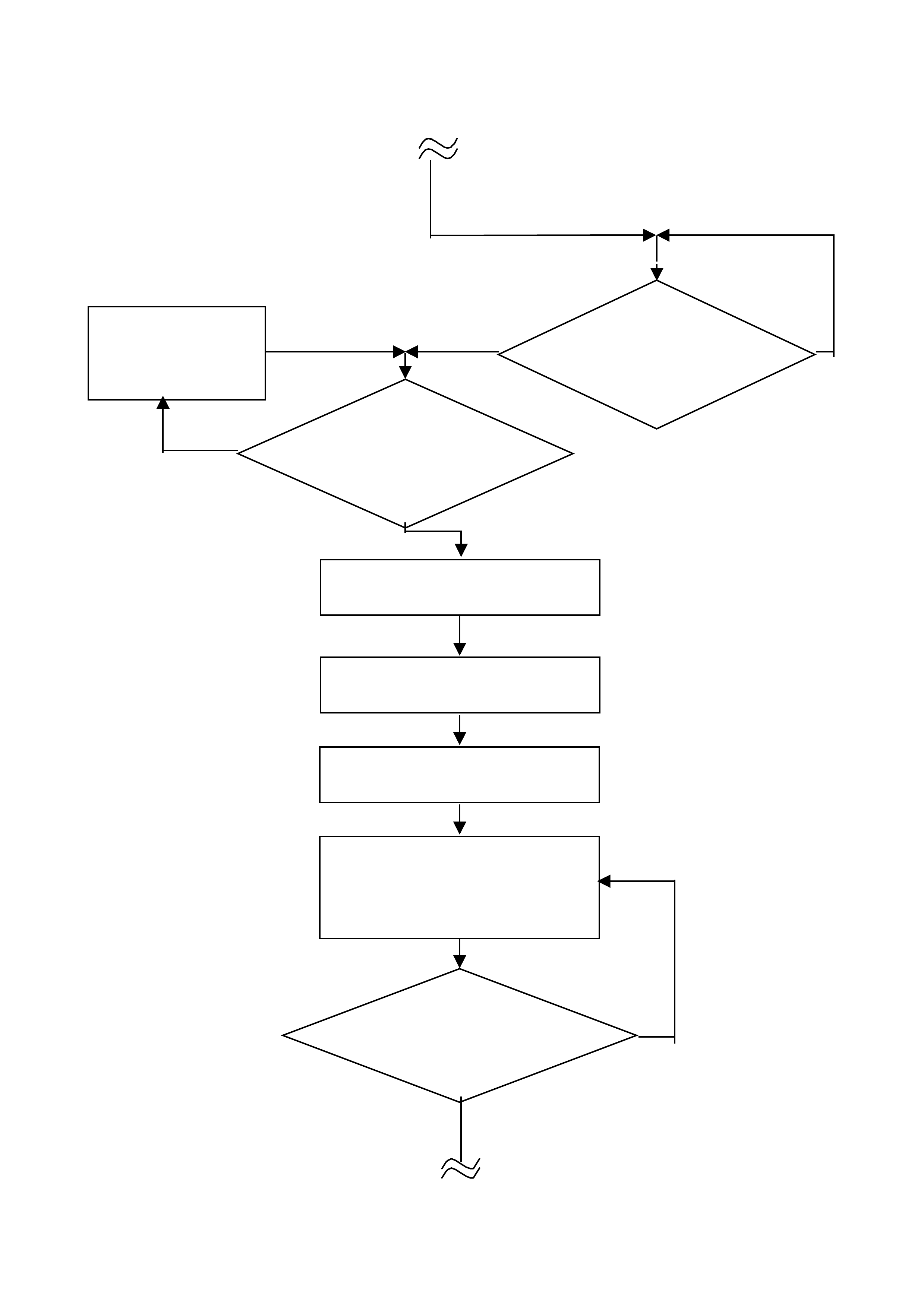
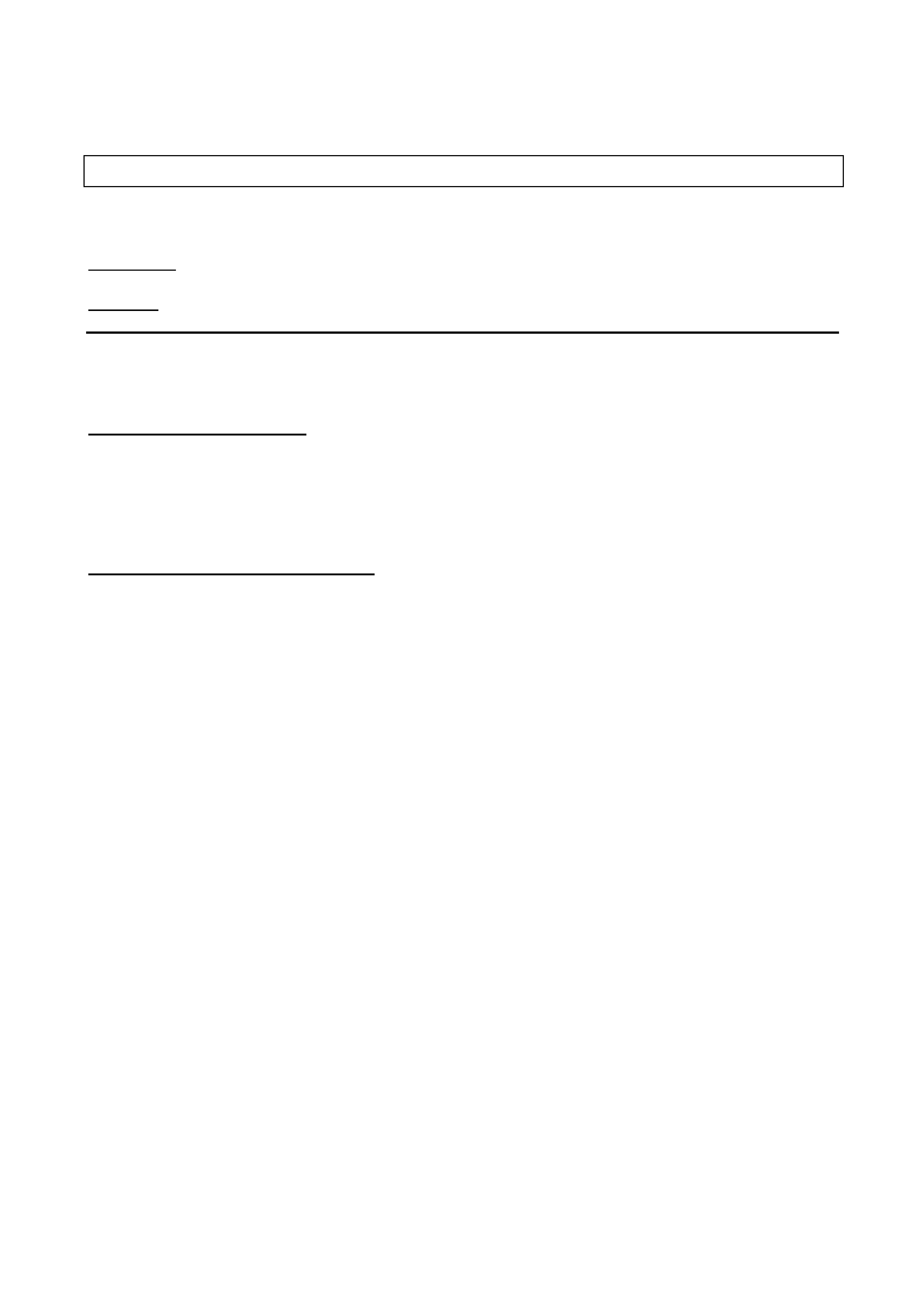
4
Tech 2 Prompts ignition
to be turned on. Turn
ignition on.
Is System ID
displayed
Ignition Not On
Body menu will be
displayed select F5:
In the program menu box
select F0: Instrument
Using the ‘next’ sof t key step
through each parameter until
you reach SRS Lamp screen
Has SRS Lamp
Screen been found
No
Yes
If no data is displayed
follow the SRS
diagnostics procedure
in SIP
Press ‘Confirm’ soft key
TWICE
Yes
No
5
SRS lamp
enabled SRS lamp
disabled
Use ‘Modify’ soft key to change
the setting to Enable
Press ‘Exit’ soft key to return
to the body menu screen.
Select F4: Miscellaneous In the miscellaneous test
screen select F0: Lamps
In the lamp screen select
‘SRS Lamp’
Exit system
END
On the
instrument cluster check
if the SRS warning lamp illuminates
by toggling the ‘ON’ ‘OFF’
soft keys.
Follow the SRS
diagnostics
procedure
‘OK’
NOT ‘OK’
Use ‘Next’ soft key to step
through each parameter until
‘Abort’ is prompted
Use ‘next’ soft key to step
through remaining parameters
until ‘Program’ is prompted
Press ‘Abort’ soft key
Press ‘Program’ soft key
Press ‘Confirm’ soft key
1
RE-ISSUED (ISSUE NUMBER 3)
PRODUCT CAMPAIGN BULLETIN
00-H-02 December 22, 2000
SUBJECT : FUEL FEED HOSE
MODEL : VS & VT SERIES 5.0 LITRE & 5.7 LITRE (NON GEN III) ENGINE
This bulletin announces the initiation of a saf ety related recall on some VS series III and VT Series
I vehicles built with 5.0 litre & 5.7 litre (NON GENIII) V8 engines.
DESCRIPTION O F DEFECT
Investigation has shown that a number of vehicles in a specific batch may have been fitted with a
fuel f eed hose that does not fully meet specificat ion. The ef f ect may be thermal deg radation of the
hose material at the f uel r ail. T his deg radation of the f uel hose could result in a f uel leak and in the
worst case the fuel could contact ignition cir c uit r y and ig nit e .
DETAI L S OF AFFECTED VEHICLES
A total of 3,043 VS Series III vehicles and 11,591 VT series I Commodore vehicles are aff ected.
AFFECTED VS SERIES III VEHICLES
• With XT9 (emission upgrade) option only
• Built between November 1998 and October 2000
• Vehicles with LB9 option 5.0 litre V8
• Vehicles with L98 option 5.7 litre (NON GEN III) V8 engine
• HSV Maloo with 5.0 litre V8 engine.
• HSV Grang e with 5.0 litre V8 engine
• HSV Grange with 5.7 litre (NON GEN III) V8 engine
AFFECTED VT SERIES I VEHICLES
• Built f r om start of VT I production (July 1997 to June 1999)
• Commodore / Calais with LB9 5.0 litre V8 engine
• Commodore / Calais with L98 5.7 litre (NON GEN III) V8 engine
• All VT series I - HSV vehicles with LB9 5.0 litre V8 engine
• All VT series I - HSV vehicles with L98 5.7 (NON GEN III) litre V8 engine
NOTE: GENIII V8 ENGINE IS NOT AFFECTED BY THIS RECALL
For the purposes of electronic flagging of vehicles within dealer service departments, use the
following Product ion Ser ial Num ber ( PSN) range f or the aff ected vehicles (L224939 to L636054)
2
The following chart can be used to assist with the interpretation of the vehicle identification serial
numbers (I SO VIN) in your Electronic Repair Order System.
6H8VSK80UXL691320
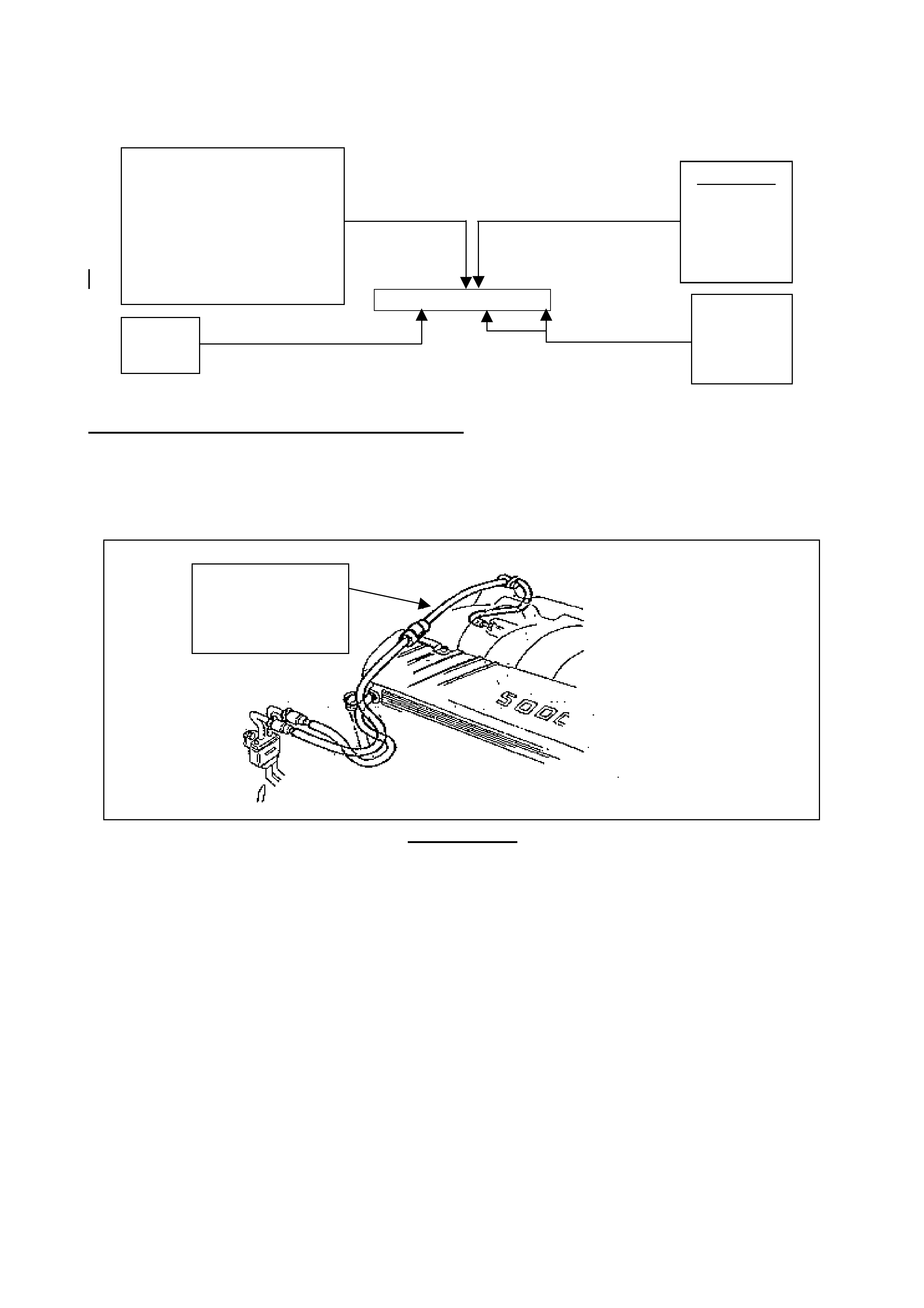
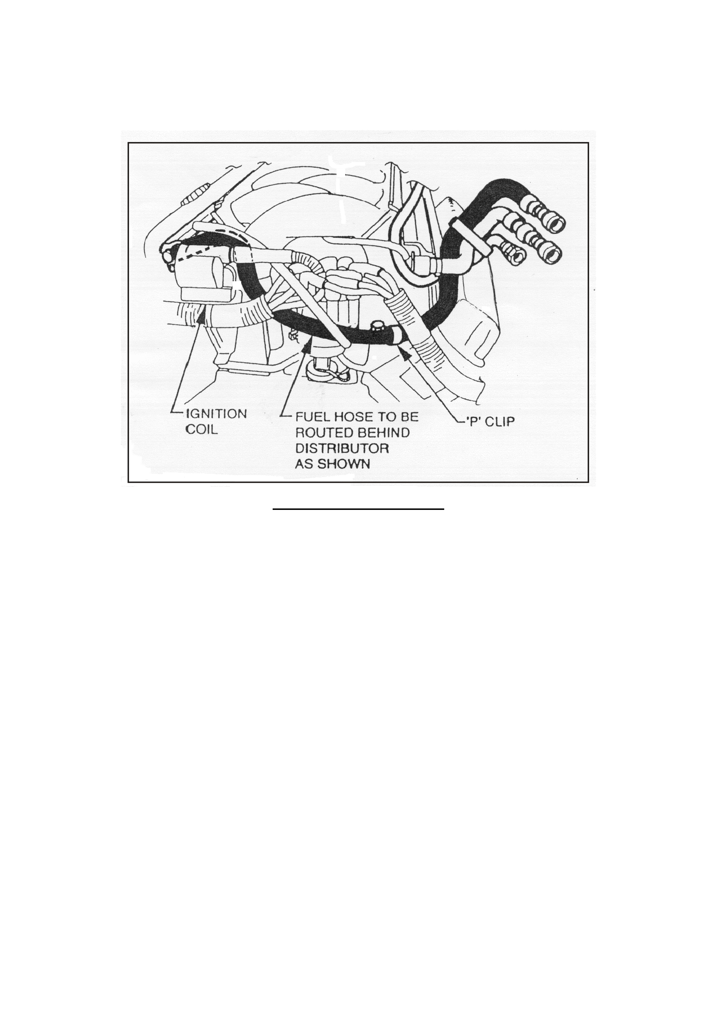
IMPO RTANT EXCLUSIONS FO R VS VEHICLES
If you are presented with a customer that has a Customer Notification of Recall Letter and their
vehicle has the fuel feed hose routed above the engine as per diagram 1.0 below DO NOT
CAMPAIGN THE VEHICLE. Ensure that a warranty claim is submitted for inspection only (Refer
Warr ant y Claim Inform ation)
DIAGRAM 1.0
Model Year
“V” = 1997
“W” = 1998
“X” = 1999
“Y” = 2000
“1” = 2001
PSN
L224939
To
L636054
VS
“U” for VS 5.0 litre V8
“L” for VS 5.7 litre non GENIII
VT
“M” for VT 5.0 litre V8
“N” for 195Kw VT 5.0 litre V8
“P” for VT 5.7 litre non GENIII
Fuel Feed Hose
routed above the
engine is NOT TO
BE CAMPAIGNED
S = VS
T = VT

3
OWNER NO TIFICATIO N
Owners will be contacted directly by letter from Holden, providing details of the recall and
requesting them to arrange for the campaign action to be carried out. Following is a draft of the
customer letter.
Dear Holden Customer ,
At Holden we continually strive to enhance the ownership experience of our customers through
continuous product im pr ovem ent, aftersales serv ice and ef f ective customer communicat ion.
Holden’s foremost concern is the continued safety of our customers. Accordingly the recall
campaign described below is being under t aken as a safety precaution.
Holden has been alerted to the fact that in a number of vehicles within a determined production
range, a fuel feed hose may not have been manufactured to the correct specification. In certain
circumstances the hose has the potential to thermally degrade. This degradation of the fuel hose
could result in a fuel leak and in t he worst case the fuel could contact ignition circuitry and ignite.
Our records show that your Holden vehicle was manufactured within the vehicle range which may
include this component. It is therefore necessary for you to contact a Holden dealership of your
choice as soon as possible to have the fuel f eed hose r eplaced.
All work will be carried out free of charge and provided the necessary arrangements with a Holden
dealer ar e m ade in advance, your vehicle can be r ectif ied while you w ait. The r equired w ork w ill take
approximately half an hour, although please allow, at a minimum, an additional one hour as
most cases will require the vehicle to cool down sufficiently before any rectification work can
be performed in a safe manner.
Holden has initiated this action as a precautionary measure to ensure the fuel feed system of your
vehicle is functioning correctly.
We know that eff ective communication is vit al to helping your understanding of the issues involved
and trust that this letter provides you with all the information you need. If you should have any
questions, please contact your dealer or call the Holden Recall Assistance Line - 1800 632 826,
where one of our oper ators will be pleased to assist.
Thank you for your attention to this matter. We apologies for any inconvenience this action may
cause you.
Yours Sincerely
D. McMurray
Manager Customer Assistance
Note: The section above marked in bold was an addition to the customer letter and will be
evident on all future contact letters relating to this recall.

4
DEALERSHIP ACTION REQUIRED
On presentat ion of the vehicle considered by the customer t o be affect ed by this campaign:
• Confir m t hat the vehicle is in the affected range – Refer to Details of Affected Vehicles on page
1 of t his bulletin.
• Refer to Attachm ent (A) DETAI LED TECHNICAL INST RUCTIONS CAMPAIGN 00-H-02
CAMPAIGN COMPLETION IDENTIFICATION
All campaigned vehicles must have a Campaign Completed identification label applied to the right
hand fr ont ‘A’ pillar, between the hinges, with details of the campaign, 00-H-02, Dealership code
and date legibly entered on t he label with a perm anent ink pen.
Extra campaign ident ification labels are available free of charg e from:
Moore Business Systems
Facsimile: (03) 9270 8900
Attention: Mr. Bob Curry
Quote stock No. SD 28156 on a Moore Business Systems ‘packaged goods’ order form (or
facsim ile if not available) fo r a box of 100 labels.
As an additional continuous improvement initiative, which was triggered by the dealer network,
Campaign Completion Identif ication will now also be included on the Vehicle Service Histor y Label
(SD 28177 available from Moore Business Systems). Enter an “X” at the F-4 co-ordinate of the
Vehicle Service History Label and apply it to the back of the fuse panel cover (below steering
column).
WARRANTY CLAIM I NFO RMATIO N
On completion of campaign action, dealers are requested to immediately submit a w arranty
claim.
Description: Replace Fuel Feed Hose
Labour Operat ion No: T080901
Standard T ime: 1.0 Hours
Failure Code: 96
Case Type: 08
Description: Inspect Fuel Feed Hose
Labour Operat ion No: T080902
Standard T ime: 0.2 Hours
Failure Code: 96
Case Type: 08
Please note that a 0. 5 hrs bonus is included in t he Standard T ime t o cover miscellaneous activities
associated with priority booking of customers.
Please ensure correct vehicle details are included when submitting warranty claim information as
per the norm al warranty process.
Warranty claim submission is used to update our record of campaign completion and determines
whether furt her cust omer contact is necessary to action all af fected vehicles.
Please ensure on completion of the campaign act ion t hat a warranty claim is submitted prompt ly.

5
PARTS INFORMATION
DO NOT O RDER PARTS FOR THIS CAMPAIGN FRO M HSPO
Fuel Hose Service Kits for this campaign are available through SALMAT using the attached order
form.
Controls on the quantity supplied will be enforced due t o lim it ed parts availability.
DO NOT campaign vehicles or order parts unnecessaril y!
Ensure the vehicle fall s within the guidelines specif ied in section marked:
‘DETAILS OF AFFECTED VEHICLES’.
Should you require further information or clarification on the above, then please call Oliver
Mitrovski on telephone number ( 03) 9647 7619.
Joachim Burandt
General Service M anager
Attachment A: DETAILED TECHNICAL INSTRUCTIO NS CAMPAIGN 00-H-02
Attachment B: MATERIAL ORDER FO RM
6
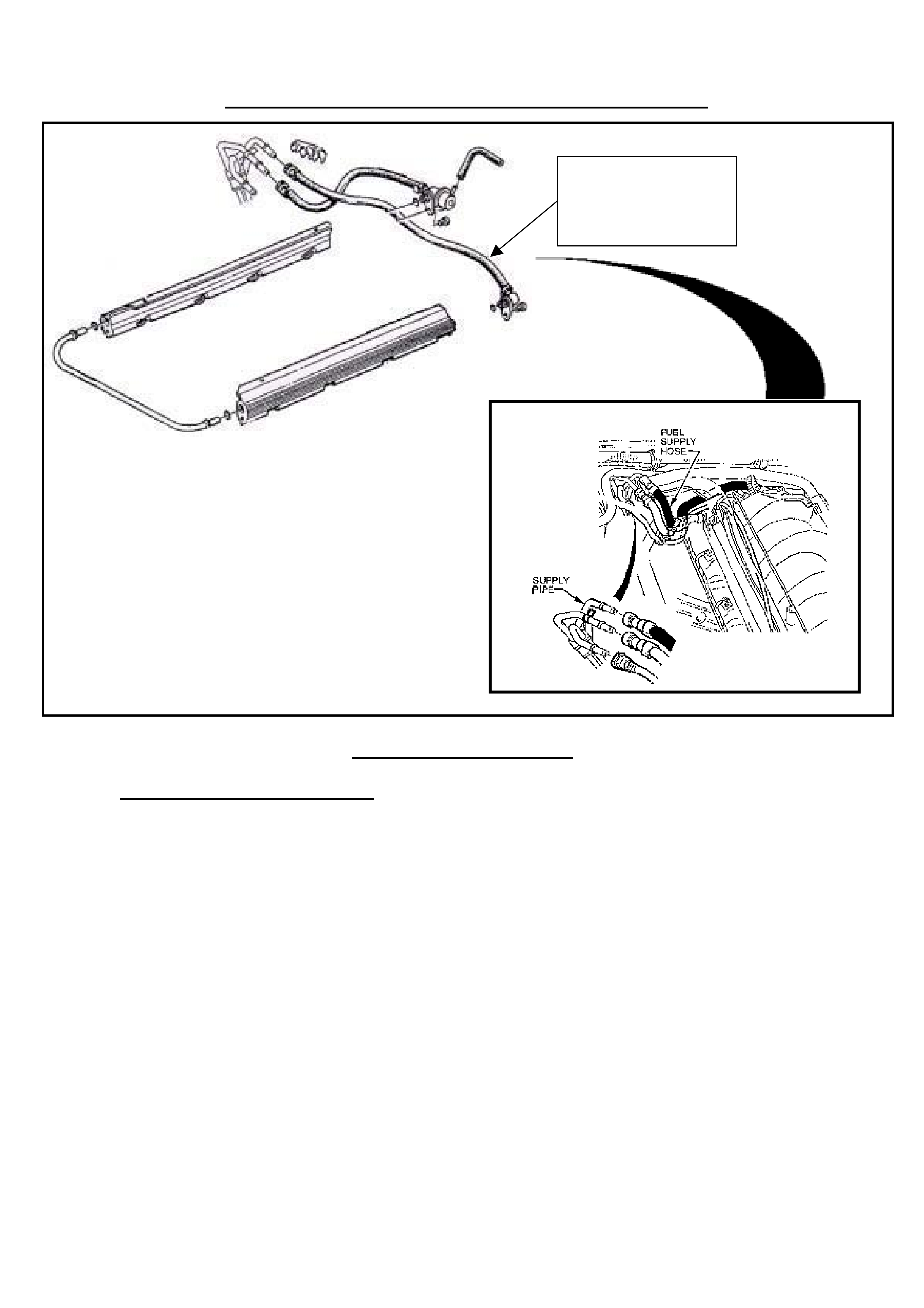
Attachment (A) DETAILED TECHNICAL INSTRUCTIONS CAMPAIGN 00-H-02
REFERENCE DIAGRAM A.1
1.0 Fuel Pressure Relief Procedure
1.1 Remove the “Fuel Pump Relay” from the engine compart ment relay housing (T he fuel pump
relay is mounted in the relay housing which is located under the bonnet, refer Fig 6C2-3-16
section 3.10 FUEL CONTROL SYSTEM in Service Inf or m ation Package ( SI P) )
1.2 With the throttle closed, crank the engine – engine may start and idle until fuel supply
remaining in the fuel line is consumed. W hen t he engine stops, engage the starter again for
10 seconds to ensure dissipation of any remaining pressur e.
1.3 Reinstall the fuel pump relay.
CAUTION: Unless t his procedure is followed before servicing the fuel lines or the fuel connections,
fuel spray into t he engine com par tment could occur.
Replace fuel supply
hose with V8 Inlet
Fuel Hose Service Kit,
92076725.

7
2.0 Remove Fuel Supply Hose.
Important not e
• If removing the fuel rail to better access t he feed hose adapter DO NO T remove one rail only
as there is potential for the fuel rail crossover pipe to be damaged which in turn could also
result in damage to the ‘O’ r ings.
• Take care not to disturb the rail to crossover pipe connections as this can potentially result in
‘O’ ring dam age
2.1 Disconnect ‘P’ clamp locat ed approximately on the centre of t he fuel feed hose.
2.2 Remove fuel supply hose highlighted in reference diagram A.1 by unscrewing the adaptor
which connects the hose to the fuel rail (A POZIDRIV® screwdriver or driver bit ONLY must
be used to remove and torque the screw which attaches the fuel feed hose adaptor to the
fuel rail). Disengage the quick fit connector which is connected to the fuel supply pipe
highlighted in reference diagram A.1. (please note the removal of the quick fit connector
requires the use of a quick connect r elease tool No. 7370).
2.3 Open 7370 tool and install over fuel feed line. Close 7370 tool and pull into fuel line quick
connect to release it from fuel feed line, pull back on quick connect to disengage hose.
(When servicing the fuel rail assembly, precautions must be taken to prevent dirt and other
contaminants from entering fuel passages. Cap the fitt ing s and passages during servicing.
3.0 Fit Fuel Supply Hose Service Kit Part Number 92076725.
Important not e
• When installing the new fuel feed hose, ensure the ‘O’ ring on the adaptor is lubricated with
clean engine oil.
• If the injector rail has been removed, ensure that before re-fitting the injector rail, that all
injector ‘O’ rings to the inlet manifold are undamaged and cleaned and coated with clean
engine oil. Replacem ent of the inj ector to inlet m anifold ‘O’ ring s is not mandat ory unless they
are damag ed. If new “O’ rings are required, use only g enuine par t s from HSPO.
• If an injector detaches from the fuel rail at any time, a NEW ‘O’ ring MUST be fitted and
coated with clean engine oil. I f new “O’ rings are r equired, use only genuine part s from HSPO.
• Assemble the fuel rail onto the inlet manifold, carefully placing the fuel injectors into the inlet
manifold ports. Install and tighten the attaching bolts. (Attaching bolt torque specification 6 –
14 Nm
3.1 Connect the new hose by fully engaging the hose quick connector to the fuel supply pipe.
Ensure the connector is fully engaged by pulling back on the connector.
3.2 Rout e the hose as per Ref erence Diag ram A.2 and at tach the adapt or end on the fuel supply
hose to the f uel rail ensuring the adaptor is correct ly aligned to the f uel rail. Ensure the hose
contains the ‘O’ ring on the adaptor. Using a POZIDRIV® screwdriver or driver bit ONLY,
torque the hose adapter clamp screw to 12 +/- 2 Nm.
3.3 Fit the ‘P’ clamp supplied in the service kit to the fuel supply hose between the white marks
on the centre of the hose, and attach it to the right hand cylinder head. Start vehicle and
visually inspect the adaptor and quick f it end of hose f or evidence of any leak age. If leak age
is evident go back t o section 1.0 and repeat the procedure. If no leaks are evident attach the
Campaign Complet ion label applied to t he rig ht hand f r ont ‘A’ pillar , bet ween the hinges, with
details of the campaign, 00- H-02, Dealership code and date leg ibly enter ed on the label with
a permanent ink pen.
8
Additionally enter an “X” at the F-4 co-ordinate of the Vehicle Service History Label (SD 28177
available from Moore Business Systems) and apply it to the back of the fuse panel cover (below
steering column).
REFERENCE DIAGRAM A.2
9
Attachment (B)
MATERIAL ORDER FORM
SAFETY RELATED RECALL 00-H-02
Fax No.: (03)-9251-6266
Attention: Luke Jones
PLEASE SUPPLY QUANTITY OF FUEL HOSE SERVI CE KIT AS NOTED BELOW.
NOTE: Only order sufficient quantities for pre-booked vehicles. Strict controls on the
quantity of parts supplied will be enforced due to limited parts availability.
FUEL HOSE SERVICE KIT Qty:
_______________________________________________________________________________________
From Dealer Code: ___________ Date: __________________
Dealership Name: ______________________________________
Person Ordering Parts (Contactable Person): ________________________________
(please PRINT your name)
Fax This Form To : SALMAT (03)-9251-6266