
222000000000 SSSEEERRRVVVIIICCCEEE TTTEEECCCHHHLLLIIINNNEEESSS
© 2006 GM Holden Ltd. A.B.N. 84 006 893 232
Service Department
A “HOLDEN” Product.
BRISBANE SYDNEY MELBOURNE ADELAIDE PERTH
100mm
150mm
REVISED EVAPORATOR THERMISTOR POSITION (February 2000)
TF RODEO V6
GROUP 2
Information from the field has revealed that V6 Rodeo vehicles may experience evaporator ice –
up on 100km+ distance trips. Evaporator ice up is usually described as poor blower fan output
with large quant it ies of water draining f r om the evaporator when the vehicle is stationary.
Air International has developed a revised thermistor position to prevent the evaporator
temperature dropping below zero degrees which causes the condensation on the evaporator to
freeze.
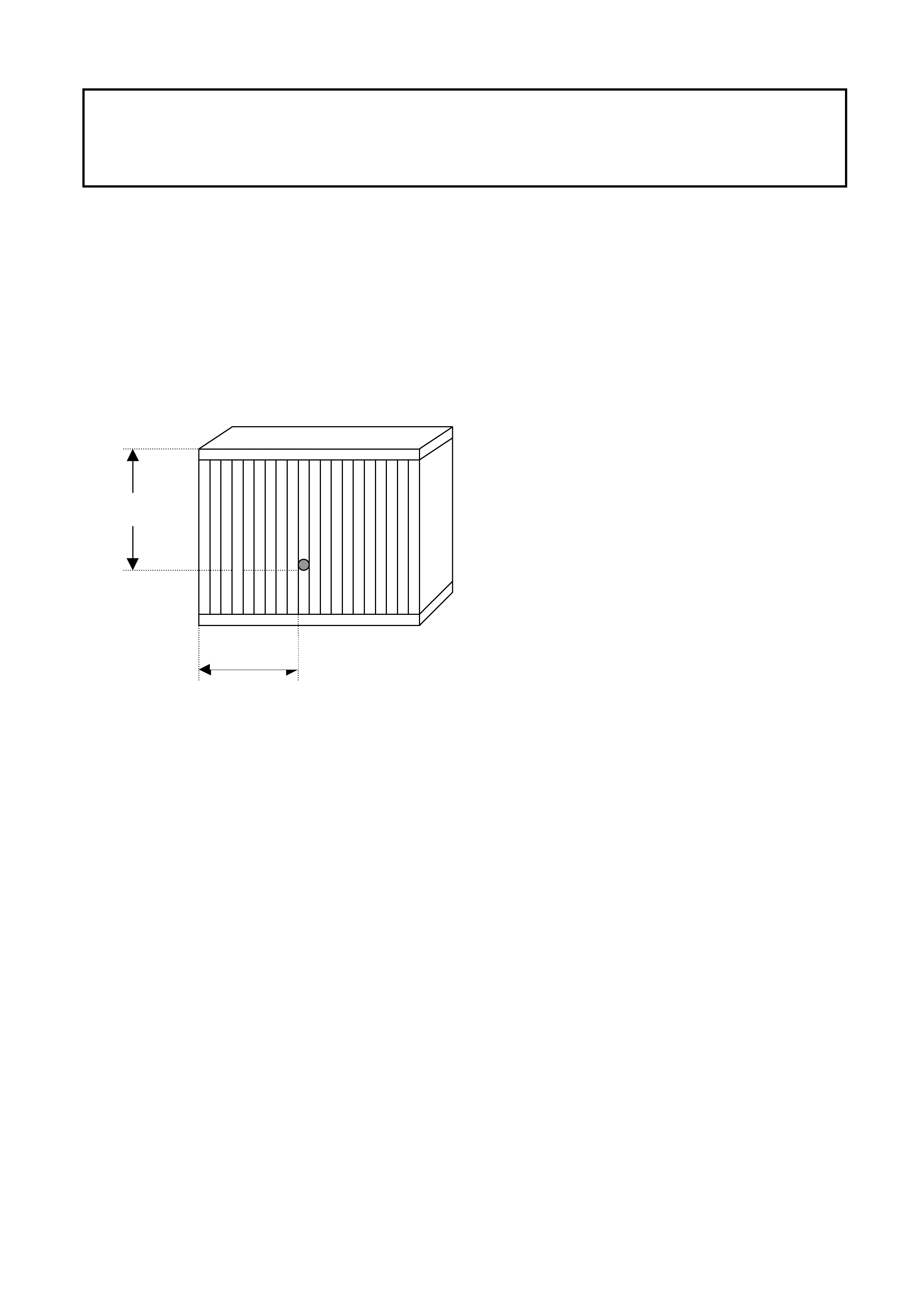
Refer to the diagram below for the revised thermistor position, and disregard any prior bulletins
referring to this subject.
Note- Evaporator viewed from the air
off side. Thermistor tip location
should be 150 mm from the upper
side and 100 mm (10 fins) from the
left side of the core.
The thermistor clip is approx. 20mm
from the plotted sensor tip point.

CRANKSHAFT PULLEY BOLT (February 2000)
RODEO with 4JB1T
GROUP 6A
From engine number: 586429 (build - December 99), the crankshaft front pulley bolt tension for
the 4JB1- T engine has been increased to 24+/- .5kg.m (174+/- 4lb.ft, 235+/-5N.m) from 21+/- 2
kg . m (152+/- 14lb. ft, 206+/ - 20 N.m).
All relevant workshop manuals should be chang ed accor dingly.
Dealers aware of any failed or loose bolts in engines manufactured after the above breakpoint
should notif y I-GM TAS immediately. (PH: 1800 032 608 )

COOLANT SPECIFICATIONS (June 2000)
ALL IGM MODELS
(GROUP 6K)
The attached table is a reference guide to coolant specifications for all Isuzu vehicles.
Vehicle Model Factory Fill
Spec Recommended
Change at Alternative
Replacement
Coolant Spec
Recommended
Change at
~1998, R7 Rodeo
~1997, L5 Jackaroo
1996, UT Frontera
~1996, Isuzu Truck
HN2043
2 Years / 40 000
HN2217
Or
GM6277m
5 Years / 100 000
(Max)
5 Years / 100 000
(Min)
1997~, Isuzu Truck
HN2217
2 Years / 40 000
GM6277m
5 Years / 100 000
(Min)
1999~, R9 Rodeo
1998~, U8 Jackaroo
1997, UT Frontera
MX, Frontera
HN2217
5 Years / 100 000
(Max)
GM6277m
5 Years / 100 000
(Min)
Suburban
GM6277m
(Dexcool)
5 Years / 100 000
(Min)
Note – An inspection of cooling system components for corrosion should be carried out prior to
refilling with new coolant. Failure to identify a problem at this point may be a costly experience at a
later date. When using an alternative to the factory fill coolant the cooling system must be
thoroughly flushed prior to refilling.
ANTI THEFT/KEYLESS ENTRY DIAGNOSIS (June 2000)
JACKAROO
(GROUP 12)
The charts below are quick reference material that is intended to be used in conjunction with the
relevant workshop manual section (8H) and wiring diagrams (8D – 242) in the current Jackaroo
workshop manual.
DOOR SWITCH DIAGNOSIS
Front Door Key Swit ch
Detect Switch Circuit - Open
FUNCTION OPERATION
Anti – Theft LED No effect
Remote Locking No effect
Mechanical Locking No effect
Alarm System ( Arming ) Mechanical key will not arm system
Alarm System ( Disarm ) Mechanical key will not arm system
Note Unlocking the door with the mechanical key will activate the alarm system.
Detect Switch Circuit – Short to Ground
FUNCTION OPERATION
Anti – Theft LED No effect
Remote Locking No effect
Mechanical Locking No effect
Alarm System ( Arming ) No effect – (see below)
Alarm System ( Disarm ) No effect – (see below)
Note Locking / Unlocking the door with the snib button will arm / disarm the alarm
system
Tamper Switch Circuit - Open
FUNCTION OPERATION
Anti – Theft LED No effect
Remote Locking No effect
Mechanical Locking No effect
Alarm System ( Arming ) No effect
Alarm System ( Disarm ) No effect
Note Open circuit is the normal state for this switch. Forcing the lock will not activate the alarm
when this condition exists
Tamper Switch Circuit – Short to Ground
FUNCTION OPERATION
Anti – Theft LED Flashes at constant 2Hz with doors closed
Remote Locking Inoperative
Mechanical Locking No effect
Alarm System ( Arming ) Inoperative
Alarm System ( Disarm ) Inoperative
Door Lock Key Switch
Door Lock Key Switch - Open
FUNCTION OPERATION
Anti – Theft LED No effect
Remote Locking No effect
Mechanical Locking No central locking from failed door
Alarm System ( Arming ) No effect
Alarm System ( Disarm ) No effect
Note Central locking is still available from arm – rest master switch
Door Lock Key Switch (Lock) – Short to Ground
FUNCTION OPERATION
Anti – Theft LED No effect
Remote Locking Remote unlock only
Mechanical Locking No central locking from failed door
Alarm System ( Arming ) No effect
Alarm System ( Disarm ) No effect
Note Central locking is still available from arm – rest master switch
Door Lock Key Switch (Unlock) – Short To Ground
FUNCTION OPERATION
Anti – Theft LED No effect
Remote Locking Remote lock only
Mechanical Locking No effect
Alarm System ( Arming ) No effect
Alarm System ( Disarm ) No effect
Hood & Dome Lamp Switches
Hood Switch Circuit - Open
FUNCTION OPERATION
Anti – Theft LED No effect
Remote Locking No effect
Mechanical Locking No effect
Alarm System ( Arming ) No effect
Alarm System ( Disarm ) No effect
Note Open circuit is the normal state for this switch. Forcing the hood will not activate the
alarm when this condition exists
Hood Switch Circuit – Short to Ground
FUNCTION OPERATION
Anti – Theft LED Normal operation with doors open, but off when
doors locked
Remote Locking No effect
Mechanical Locking No effect
Alarm System ( Arming ) Inoperative
Alarm System ( Disarm ) Inoperative
Dome Lamp Switch ( Door Sw.) Circuit - Open
FUNCTION OPERATION
Anti – Theft LED No effect
Remote Locking No effect
Mechanical Locking No effect
Alarm System ( Arming ) No effect
Alarm System ( Disarm ) No effect
Note Open circuit is the normal state for this switch. The dome lamp will not activate when the
door is opened
Dome Lamp Switch (Door Sw.) Circuit – Short to Ground
FUNCTION OPERATION
Anti – Theft LED See note below
Remote Locking Inoperative
Mechanical Locking No effect
Alarm System ( Arming ) Inoperative
Alarm System ( Disarm ) Inoperative
Note The Anti – theft LED will flash at 2Hz for 30 secs. After a remote keypad button is
depressed, then go out. The LED will remain on continuously while the unlock button is
depressed on the keypad.

REVISED FUEL FILTER ASSEMBLY (June 2000)
JACKAROO 4JX1 DIESEL
(GROUP 6M)
When used in cold conditions (Below 0°C) some 4JX1 Jackaroo vehicles may experience fuel flow
difficulties through the filter assembly upon cold start up.
The restriction is due to trapped air freezing on the filter element creating a barrier through which the
fuel is unable to flow. To overcome this concern, Isuzu has released a revised filter assembly that has
improved air breathing/bleeding abilities.
The part number for the revised filter assembly is 8972245600.
ISUZU-GM SERVICE TECHLINE _________________________________________________________________ AUGUST 2000
12 12
RIDE HEIGHT SPECIFICATIONS
RODEO & JACKAROO GROUP 3
Detailed below are the ride height specifications for Jackaroo (UBS) and Rodeo (TF). For details
on adjustment refer to the relevant workshop manual ( Section 3 ).
Note- All measurements should be made when the vehicle is at curb weight and with bump stops
in good condition. (Curb weights can be found in the relevant owners handbook)
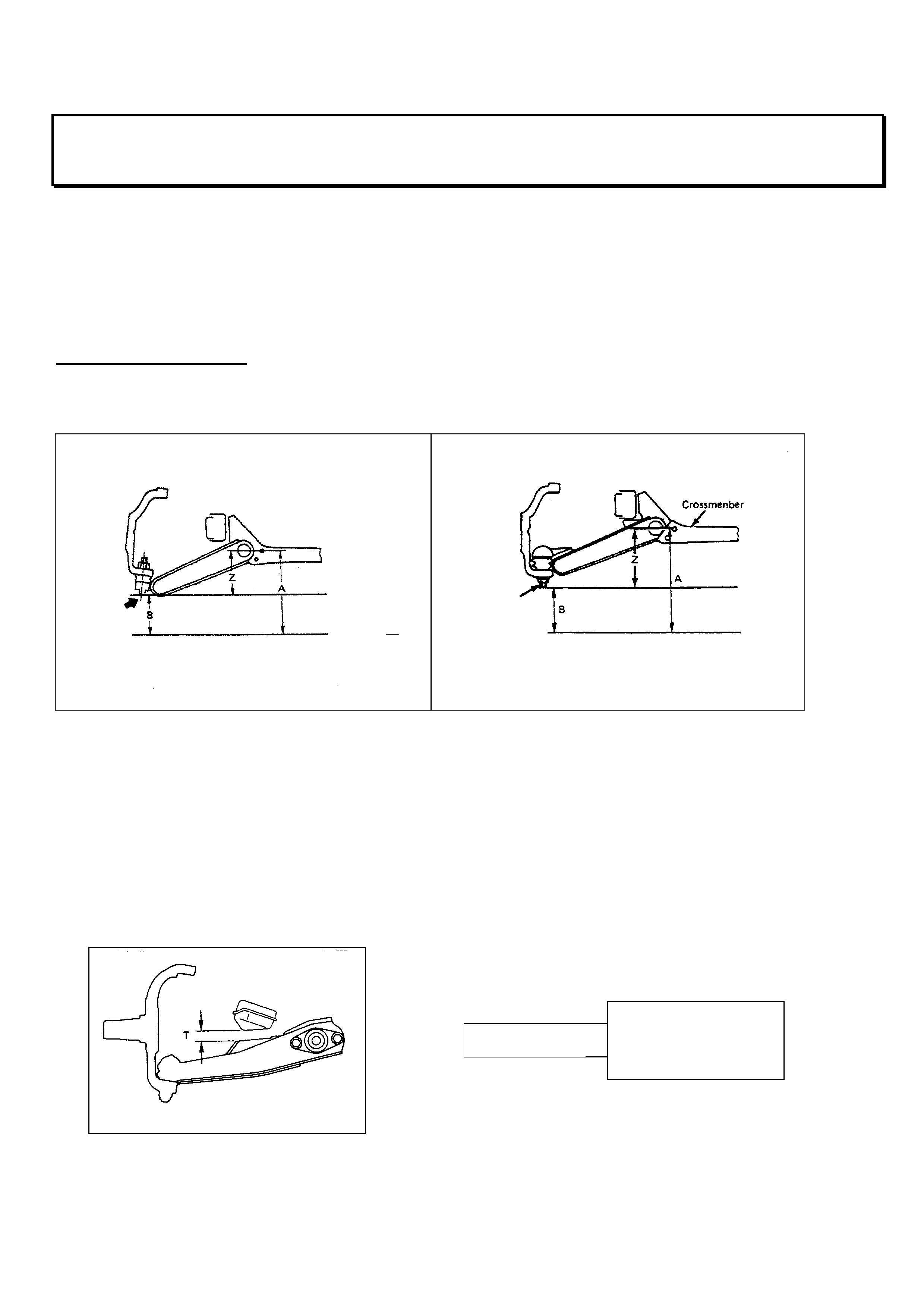
Current model Rodeo
Front- There are two settings, one for TFS (4x4) and TFR25 (4x2, V6), the other for TFR (4x2).
There is a simpler method that requires the construction of a measuring tool. The tool can then be
placed between the bump stop and the lower control arm to indicate the trim height. The diameter
of the tool for 4x2 excluding V6 is 45mm, for 4x4 and V6 17mm (refer below)
Note- this method can only be used if the vehicles bump stops are in good condition.
Z =56 mm
TFR (4x2) EXCLUDING V6
ENGINE
Z=130mm
TFS (4x4) & TFR V6 (4X2 WITH
V6 ENGINE
)
TFS & TFR V6 TFR EXCLUDING V6
17 mm 45mm
ISUZU-GM SERVICE TECHLINE _________________________________________________________________ AUGUST 2000
13 13
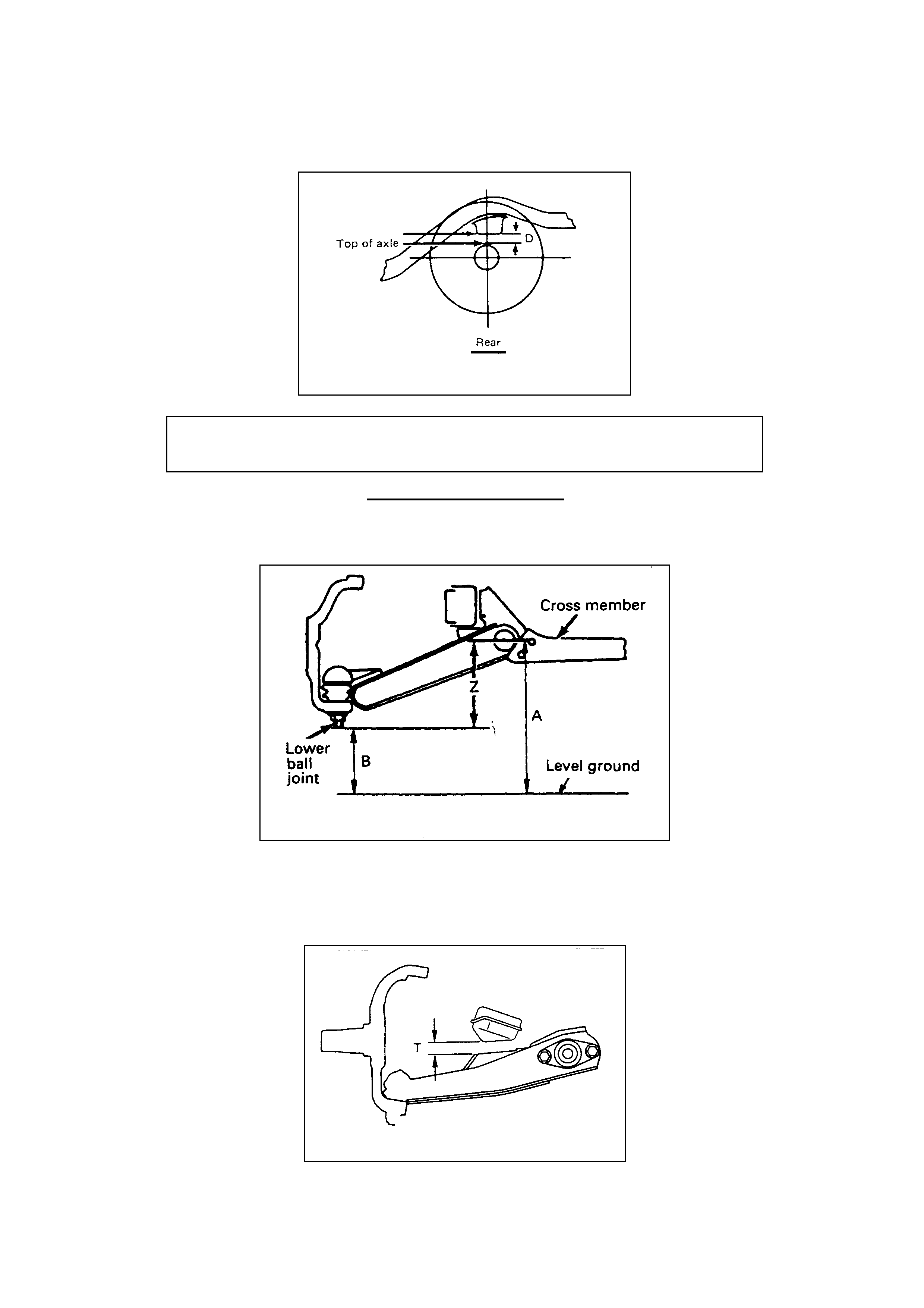
Rear- The ride height is measured as a clearance between the bump stop and the top of the
axle(refer below)
Current model Jackaroo
Jackaroo trim height is 139 +/- 5mm (refer below).
The trim height can also be checked by placing a tool between the bump stop and the lower
control arm. The Jackaroo tool diameter is 24mm.(refer below)
The ride height for TFS (4x4) and TFR25 (4x2 V6) is 95mm, and for
TFR (4x2)is 90mm
Z = 13 9mm +/- 5 mm
T= 24mm

ISUZU-GM SERVICE TECHLINE _________________________________________________________________ AUGUST 2000
14 14
INTERCOOLER/AIR DUCT OIL CONTAMINATION
DIESEL JACKAROO & RODEO GROUP 6A
I-GM has recently received a large number of inquiries regarding acceptable oil contamination on
4JX1 and 4JB1 engine air intake systems.
It should be noted that crankcase ventilation may cause a light coating of oil throughout the intake
ducting as part of normal engine operation, however it is not normal to have oil collecting or
pooling.
If confronted with an engine that has excessive oil contamination in the intake system, it is
suggested that thorough examination be undertaken to determine the origin of the oil, e.g.
crankcase breather or turbo seal. If not immediately obvious, the contaminated parts should be
cleaned and the vehicle monitored at short intervals.
CHECK ENGINE LIGHT ILLUMINATING
V6 LPG RODEO GROUP 6C
Rodeo vehicles fitted with approved LPG kits may experience a situation where the check engine
light is illuminated and DTC P0171 is present in the ECM. When confronted with the above
situation, please refer to the relevant information below.
PARNELL SUPPLIED KITS.
1) The Parnell system will set a lean code after the vehicle has been operated until the LPG
cylinder is empty. During this running period the engine is operating on vapor only, as the liquid
has been consumed and all that remains is indeed vapor. This scenario is a function of the
ECM performing correctly as the engine has experienced a lean condition (as it would when
running out of petrol) and has recorded the appropriate DTC.
Customers should be informed of the above condition and advised not to run on LPG empty.
2) Parnell systems fitted with the CLS2000 processor (located behind the drivers kick panel) may
need a software upgrade, to version V65 (printed on the processor). The upgraded processor
will be supplied by Parnell on a change over basis.
IMPCO
The impco system sets a lean code as a direct result of set operating parameters. This code is
apparent mainly on automatic TF's, it normally sets during coast or when the system is leaning off.
At this stage there is no repair for this condition, Impco are investigating the concern and IGM will
advise when a field fix is developed.
Dealers are advised to confirm if the code sets on petrol. If the code sets while the vehicle is on
petrol, normal diagnosis should be performed. However if the code does not set on petrol the car
should be released, the owner advised and rebooked when a repair is advised.
ISUZU-GM SERVICE TECHLINE _________________________________________________________________ AUGUST 2000
15 15
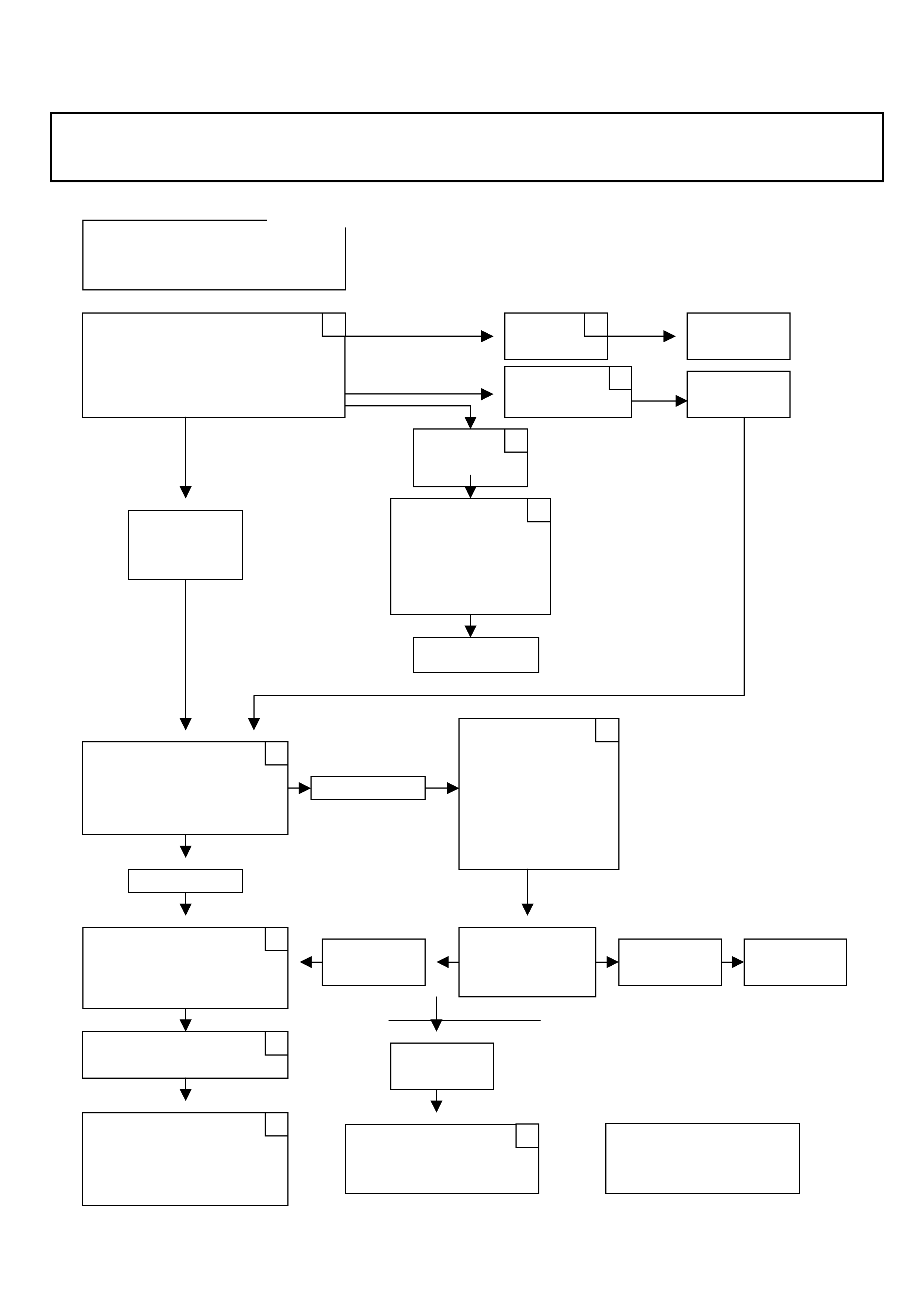
4JX1 DIFFICULT S TART PRE – CHECK
DIESEL JACKAROO GROUP 6C
IDENTIFY OIL
VISCOSIT
Y
GRADE
MANUFACTURER
OPERATE FUEL
PRIMING PLUNGER
UNTIL FIRM.
CRANK VEHICLE
DEFINE CRANK
Time: secs.
Engine crank RPM:
LOCATE SOURCE OF
AIR AND REPAIR AS
PER SHEET No. 2
HIGHER
THAN
10 SECS.
TURN ON IGNITION
WAIT FOR GLOW INDICATOR
TO GO OUT.
STARTS O.K.
O.K.
DRAIN / FILL
WITH CORRECT
SPEC. (2 TIMES)
REPLACE BOTH
OIL FILTERS
VERIFY
CHECK BATTERY
RE-CHARGE
CHECK TERMINALS
REPLACE AS
NECESSARY
O.K.
CONFIRM
START
O.K.
NO START
OBD1
SYSTEM CHECK
AS PER MANUAL
BELOW
10 SECS.
MORE THAN
100 RPM
LESS
THAN 100 RPM
INCORRECT
NO START BELOW
5 SECS.
CORRECT
INSTRUCTIONS
COMPLETE
RING - TAS.
Note- Copy this sheet and mark the box in the
top right corner as each step is completed.
4JX1
–
DIFFICULT START PRE - CHEC
K
ISUZU-GM SERVICE TECHLINE _________________________________________________________________ AUGUST 2000
16 16
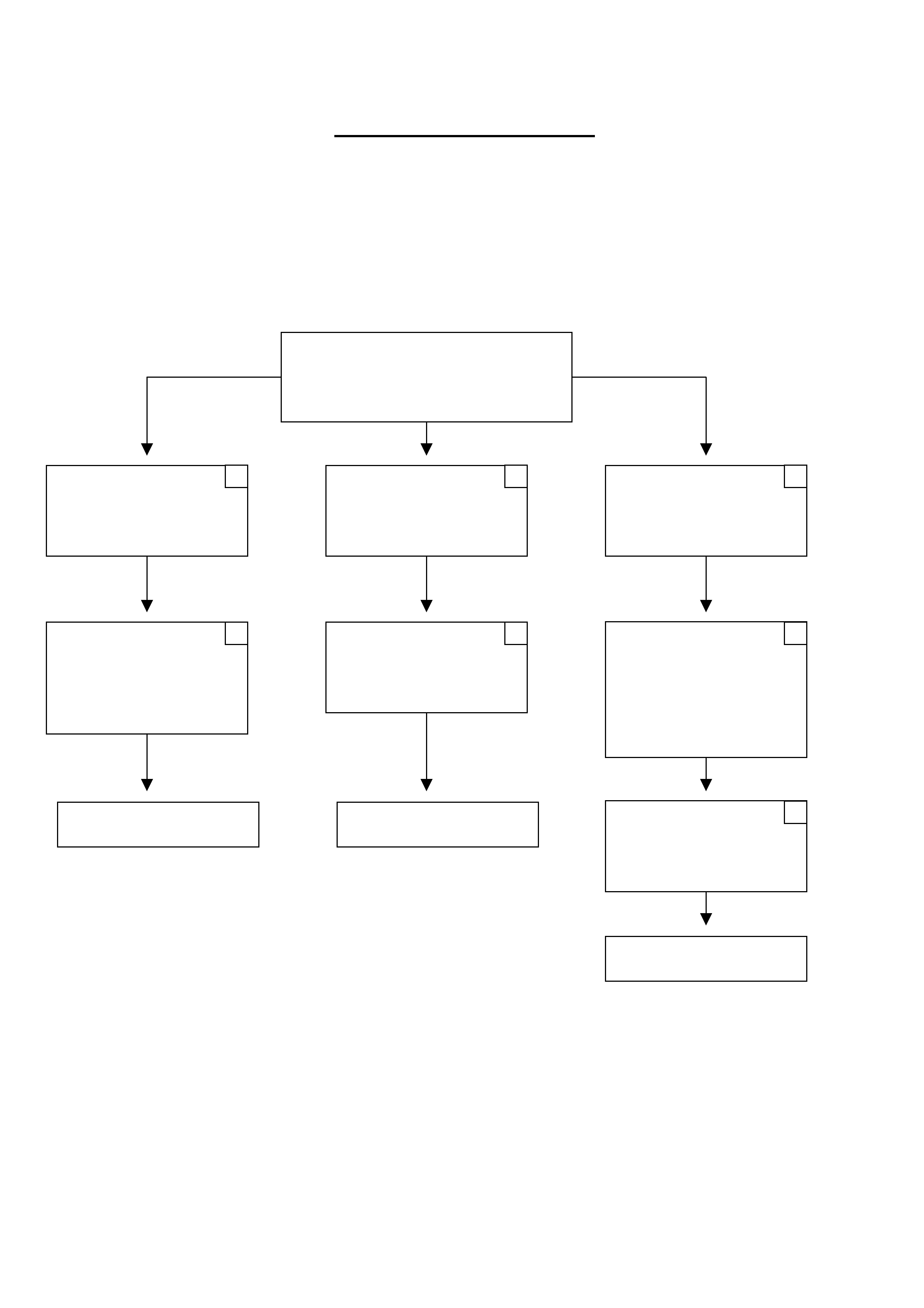
4JX1 - DIFFICULT START
(Sheet 2)
Step 1) Fit clear hose between filter housing outlet and lift pump.
Step 2) Fit clear hose on Tank return at rear of head.
Step 3) Fit clear hose between tank & filter housing inlet.
CONFIRM FILTER SEAL
CONFIRM FUEL FILTER
HOUSING (JUNE T/L )
PRODUCTION CHANGE
VERIFY REPAIR
INSPECT FUEL PIPES
FOR LEAKS AND
REPAIR
INSPECT INLET
FITTING TO HEAD FOR
TIGHTNESS AND
LEAKS.
CONFIRM INJECTOR
"O" RING
REWORK AS PER ADL
AIR OR OIL IN
SYSTEM AT THE
TANK RETURN
AIR IN SYSTEM
BETWEEN TANK AND
FILTER HOUSING
AIR IN SYSTEM
BETWEEN
FILTER HOUSING AND
LIFT PUMP
AIR IN FUEL
VERIFY REPAIR
CHECK INJECTOR
COPPER SEALS,
"O" RINGS AND
RE-TORQUE
VERIFY REPAIR