
222000000111 SSSEEERRRVVVIIICCCEEE TTTEEECCCHHHLLLIIINNNEEESSS
© 2006 GM Holden Ltd. A.B.N. 84 006 893 232
Service Department
A “HOLDEN” Product.
BRISBANE SYDNEY MELBOURNE ADELAIDE PERTH

HOLDEN SERVICE TECHLINE _____________________________________________________________JANUARY 2001
14
4JX1 INTAKE THROTTLE VALVE STICKING
DIESEL JACKAROO (UBS)
GROUP 6C TL101-6C01
Condition
Some 4JX1 engines may develop a “Hard to start” and “Lack of Engine Response” caused by the Intake
Throttle Valve sticking, the engine RPM will not increase immediately when the accelerator pedal is
depressed and the problem may disappear once the engine has warmed up. DTC 1486 (Intake throttle
position sensor high voltage) will be set. The check engine light may also illuminated.
NOTE: It is normal for the 4JX1 engine to experience some acceleration lag when cold due to oil
viscosity.
Possible Cause
Sticking butterfly valve in the Intake Throttle Valve assembly, due to an excessive build up of carbon.
Correction
After confirming the symptom and after conducting thorough investigation using the workshop manual,
Section 6 “Hesitation” it may be necessary to remove and thoroughly clean the Throttle Body.
NOTE: Do not remove or immerse the sensors into any form of cleaning agent.
AIR IN FUEL
4JX1DIESEL JACKAROO (UBS)
GROUP 6M TL101-6M01
I-GM TAS has received a large number of calls regarding air in 4JX1 fuel systems, investigations have
revealed that the fuel inlet fitting at the front of the engine was loose.
The fuel inlet has a BANJO fitting that mates to the fuel inlet pipe, the pipe has a locking nut that
tightens itself against the inlet manifold. This nut is not a locking device, it is to stop lateral movement of
the fuel pipe.
In order to check the security of the fuel pipe it is necessary to remove the cap nut and tighten the pipe
itself. However if the pipe is found to be loose replace the aluminium washer with a new one available
through HSPO. Part number 1096300830.
TORQUE SPECIFICATIONS:
FUEL PIPE: 4 Nm.
CAP NUT: 13 Nm.
BANJO FITTING: 14 Nm.

HOLDEN SERVICE TECHLINE ___________________________________________________________JANUARY, 2001
15
INJECTOR REWORK
UBS JACKAROO 4JX1 DIESEL
GROUP 6M TL101-6M02
IGM TAS continues to receive phone inquiries in regards to the Injector O – ring rework, dealers are
requested to refer to I-GM All Dealer Letter DL 04/00 for more detailed information.
Condition
Some 4JX1 engines (up to engine number 676517) may experience Diesel fuel dilution causing “Hard to
Start” and excessive smoke.
Possible Cause
The original injector O – ring hardens with age, allowing fuel to bypass and enter the crankcase.
Correction
Install the injector sealing ring kit referring to the previously released DL 04/00. From November 3rd
1999 production, engine number 676517 onwards, the material for the O - rings was changed, therefore
engines post this breakpoint should not be reworked. If an engine post this breakpoint develops fuel
dilution, a PIR should be raised.
4JX1 RAIL PRESSURE CONTROL VALVE DIAGNOSIS
DIESEL JACKAROO (UBS)
GROUP 6M TL101-6M03
Some 4JX1 engines may develop a rough idle or hesitation caused by an intermittently sticking RPCV.
An intermittently sticking RPCV is sometimes very difficult to diagnose. Therefore, to enable easier
detection of a faulty/sticking RPCV please refer to the attached graphs.
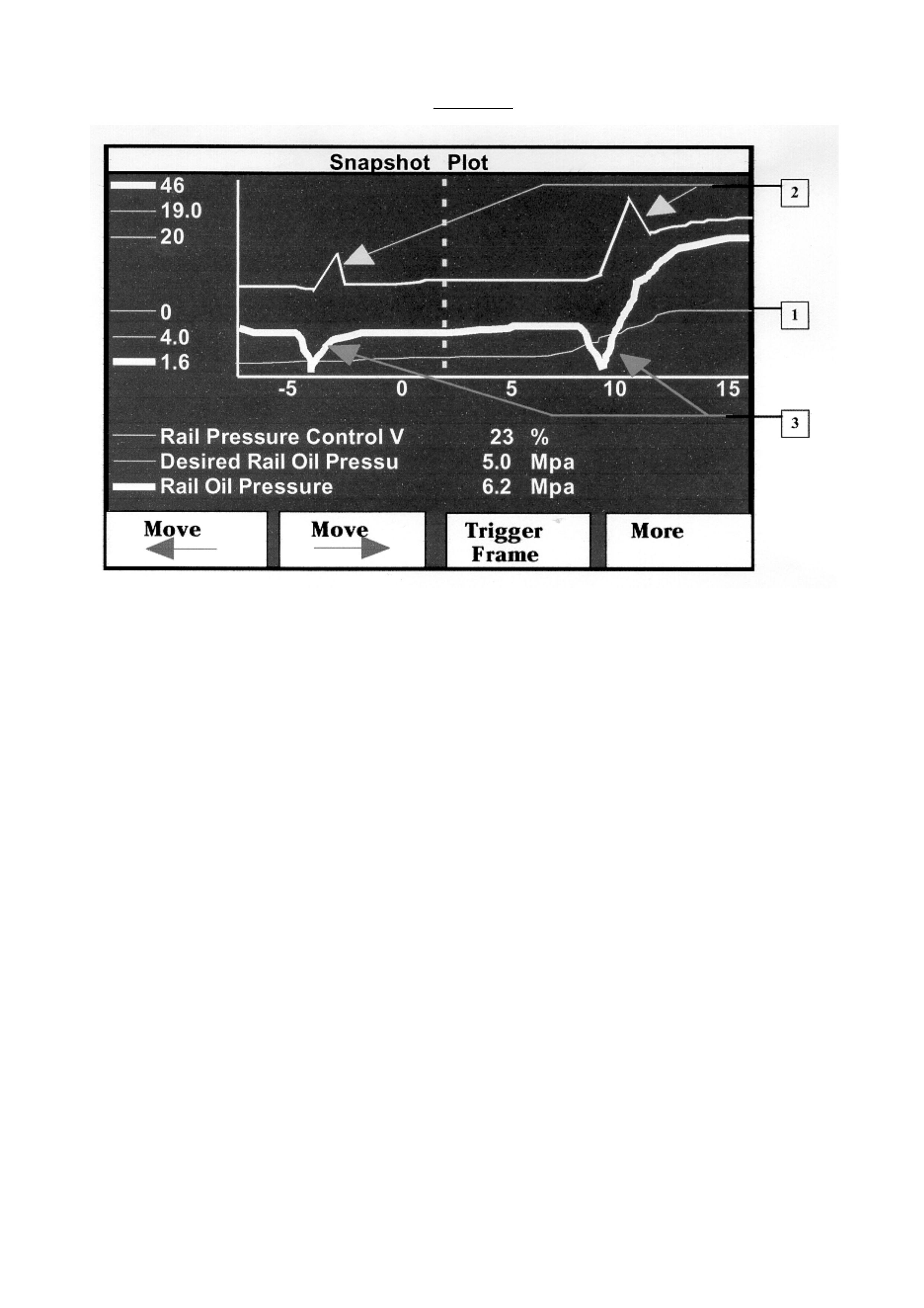
Graph 1: The graph outlines a sample of Tech 2 snapshot data that shows a faulty/sticking RPCV.
TECH 2 snapshot is most effective for checking this condition.
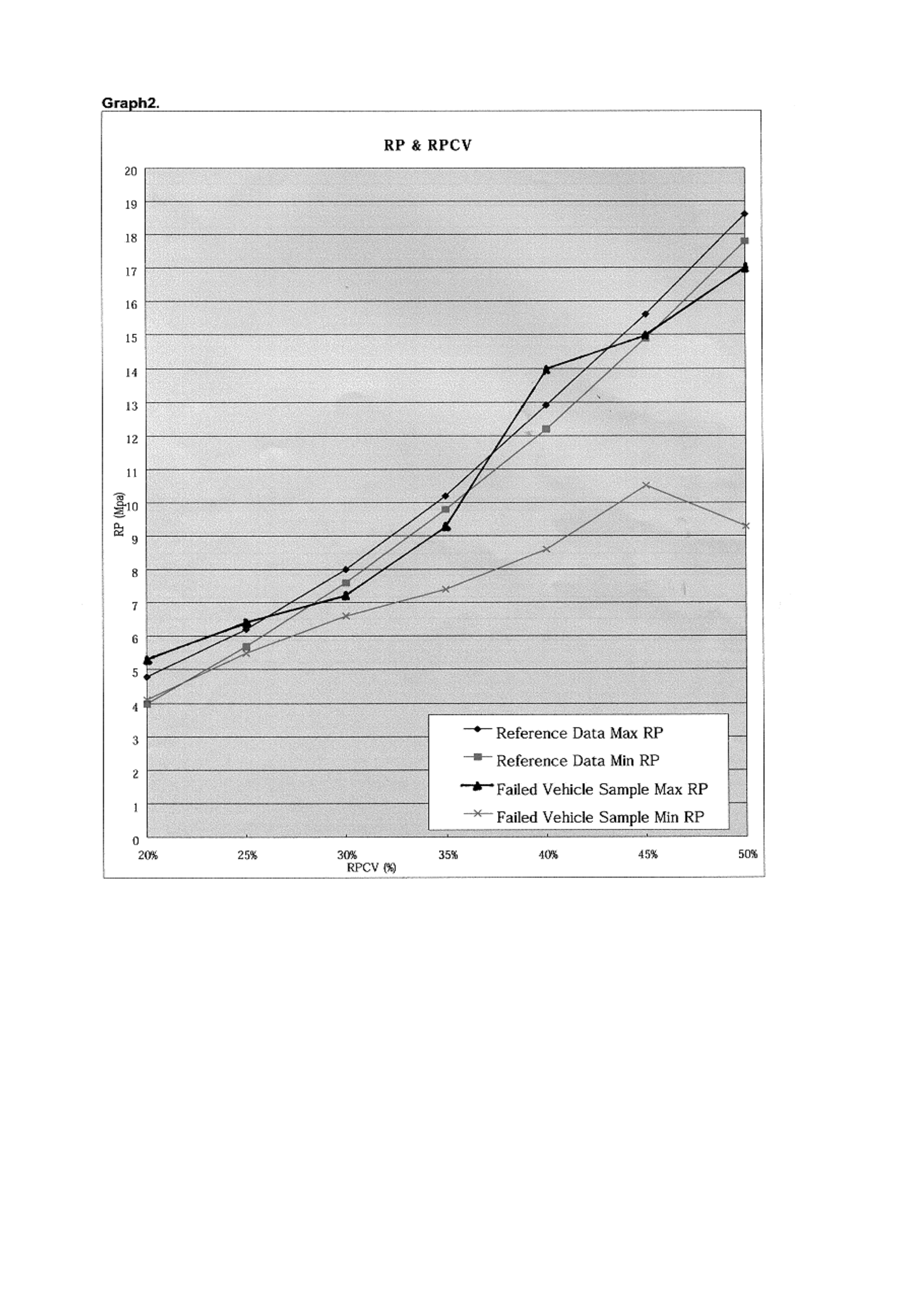
Graph 2: The graph outlines the relationship between the “Rail Oil pressure”, and the percentage of the
RPCV operating range. All of these parameters can be found using TECH 2.
NOTE: Actual pressures recorded by TECH 2 may differ slightly than those displayed on the graph; this
is due to different grades/ viscosity of engine oil and operating temperatures.
After confirming the symptom and after conducting thorough investigation using the workshop manual,
section 6 “Rough Idle”, it may be necessary to replace the RPCV, PT No: 8 97174 872 0.
HOLDEN SERVICE TECHLINE ___________________________________________________________JANUARY, 2001
16
GRAPH 1.
This graph shows a sample of a Snapshot Plot Data as displayed on Tech 2.
The graph shows the relationship between the Rail Pressure Control Valve, Desired Rail Oil Pressure
and Actual Rail Oil Pressure.
Due to an intermittently sticking RPCV, the Actual Rail Oil Pressure does not meet the Desired Rail Oil
Pressure.
1. The Desired Rail Oil Pressure increases due to engine load.
2. The PCM controls the RPCV in order to meet the Desired Rail Oil Pressure. Due to the sticking
RPCV there is a delay in the movement of the RPCV.
3. The Actual Oil Pressure is not within the tolerance of the desired Rail Oil Pressure due to the
sticking RPCV. The Actual Oil Pressure drops, that can clearly be seen from the graph.
If the above condition is displayed on Tech 2, a Hesitation or rough idle could be the result of a sticking
RPCV due to contamination or an internal failure.
HOLDEN SERVICE TECHLINE ___________________________________________________________JANUARY, 2001
17
Graph 2 clearly demonstrates the rail pressure difference between a sticking (faulty) RPCV and a good
example.

HOLDEN SERVICE TECHLINE ___________________________________________________________JANUARY, 2001
18
CLUTCH PEDAL HEIGHTS
1998 & ONWARD - JACKAROO, RODEO AND FRONTERA
GROUP 7A TL101-7A01
Recent enquiries from dealerships in regard to premature clutch wear and failure has prompted
I-GM to take this opportunity to remind all Dealership Service staff of the importance of clutch pedal
adjustment in relation to clutch durability.
Correct clutch adjustment is critical to ensure clutch life and correct operation. Dealers are advised to
ensure that clutches are adjusted as per service schedules.
TF RODEO
WITH 4JB1T WITH 6VD1 WITH 4ZE1 WITH C22NE
CLUTCH PEDAL
FREEPLAY
5.0 mm -15 mm
5.0 mm -15 mm
5.0 mm -15 mm
5.0 mm -15 mm
CLUTCH PEDAL
HEIGHT
185.5 mm –
195.5 mm
216 mm –
226 mm
216 mm –
226 mm
216 mm –
226 mm
CLUTCH SWITCH
TO CLUTCH
PEDAL
CLEARANCE
(IF FITTED)
.5 mm – 1.5 mm
.5 mm – 1.5 mm
.5 mm – 1.5 mm
.5 mm – 1.5 mm
JACKAROO
WITH 4JX1TC WITH 6VE1
CLUTCH PEDAL FREEPLAY 5.0 mm -15 mm 5.0 mm -15 mm
CLUTCH PEDAL HEIGHT 231 mm –
241 mm
238.5 mm –
248.5 mm
CLUTCH SWITCH TO CLUTCH
PEDAL CLEARANCE
(IF FITTED)
.5 mm – 1.5 mm
.5 mm – 1.5 mm
FRONTERA
WITH X22SE WITH 6VD1
CLUTCH PEDAL FREEPLAY 5.0 mm -15 mm 5.0 mm -15 mm
CLUTCH PEDAL HEIGHT 178 mm –
188 mm
178 mm –
188 mm
CLUTCH SWITCH TO CLUTCH
PEDAL CLEARANCE
(IF FITTED)
.5 mm – 1.5 mm
.5 mm – 1.5 mm

HOLDEN SERVICE TECHLINE ________________________________________________________________ FEBRUARY 2001
7
LIGHT COMMERCIAL VEHICLE
INTEGRATION INTO HOLDEN
UBS, TF, UT, Suburban
(GROUP 0B) TL102-OB02
The summarised information below is
published in fuller detail in All Dealer Letters
DL 09/01 & DL 03/01.
TAS & Security Enquiries
LIGHT COMMERCIALS VEHICLES – Rodeo,
Jackaroo, Frontera, Suburban – and the
associated work that surrounds them, have been
‘integrated’ back into Holden.
Look forward to hearing more about these
vehicles from Holden Service Engineering, in
Service Techlines and All Dealer Letters, etc,
provided by Holdens Service Head Office.
From your Service Department’s point of view –
the support for these “light commercials” is now
carried out by:
HOLDEN PASSENGER & LIGHT
COMMERCIAL VEHICLE
TECHNICAL ASSISTANCE:
PHONE : 1800 033 417
(Existing Holden TAS phone No.!).
FAX : (03) 9647 2495
(Existing Holden TAS fax No.!).
In future, if you need to call TAS about any
passenger OR Light Commercial vehicles, you
just call or fax the one number!
In addition, the people in your department who
may have to request Security Numbers for these
vehicles can now contact:
HOLDEN PASSENGER & LIGHT
COMMERCIAL VEHICLE SECURITY
ENQUIRIES
FAX NUMBER: 03 9647 2865
(Existing Holden Security Enquiries Fax No.!).
TAS Procedures
With the release of All Dealer Letter 3/2001,
Nominated Contacts should now have their
copy of the TAS Procedures Manual. This
manual contains all the necessary information
required to communicate with TAS.
Please ensure that you have access to the
manual when speaking to TAS on the phone.
Nominated Contacts should also be aware that
Holden TAS now provide technical support for
Light Commercial vehicles which include
Jackaroo, Rodeo, Frontera.
Please ensure when contacting TAS that the
correct phone selections are made to reduce
your waiting times.

HOLDEN SERVICE TECHLINE ____________________________________________________________ MARCH 2001
14
AIR CONDITIONING SERVICE
TF RODEO (APPROVED IMPCO GAS
FITTED)
(GROUP 2) TL103-0201
PROBLEM DESCRIPTION
When initially charging or servicing the A/C
system when IMPCO gas has been fitted, the
positioning of the gas converter can limit
access to the low pressure service valve.
PRODUCTION RECTIFICATION
The low-pressure service valve has been
relocated. The valve is now located at the
compressor end of the low pressure hose
rather than at the dash panel end.
SERVICE RECTIFICATION
When charging or servicing the A/C system,
access to the low pressure service valve is
best obtained through the wheel arch while
the front wheels are positioned on full-lock.
REAR BRAKE SQUEAL
RODEO (4x4 and V6 4X2)
(GROUP 5) TL103-0502
PROBLEM DESCRIPTION
Excessive squeal noise emanating from rear
brakes on application.
PRODUCTION RECTIFICATION
Revised brake shoes fitted in production:
ISOVIN: Build Date:
JAATFS25HY7103377 25/01/01
JAATFS55HY7120056 25/01/01
JAATFR25HY7108590 25/01/01
* MPATFS25 TBA
* MPATFS55 TBA
* MPATFR25 TBA
* B/P’s for vehicles manufactured in
Thailand have not yet been established,
they will be included in the Breakpoint
Summary once available.
SERVICE RECTIFICATION
For pre-breakpoint vehicles the service fix
described below, which is the same as in
Dealer Letter IGM 13/99, can be applied.
I - GM has released a modified rear brake
shoe set (part number 5878317230) to
overcome the above complaint.
Before installation of the modified shoes the
rear brake assemblies should be de-dusted
and inspected for correct operation, if no
faults are observed the drums should be de-
glazed and the new shoes installed.
To effectively monitor the success of the
revised brake components, a PIR should be
submitted for any post-breakpoint vehicles
that exhibit squeal from the rear brakes.
PARTS INFORMATION
Part No.: Description: Qty:
5878317230 Brake Shoe Set 1
WARRANTY CLAIM INFORMATION
Use existing Warranty Information from SIP
as shown:
Description Shoes and Lining
Labour Op. No. H025700
Time 1.2
Failure Code 40

HOLDEN SERVICE TECHLINE ____________________________________________________________ MARCH 2001
15
RUNNING ROUGH - MISFIRE
JACKAROO (4JX1 DIESEL ENGINE)
(GROUP 6M) TL103-0601
PROBLEM DESCRIPTION
Vehicle will miss or run rough which may be
caused by a defective injector. Investigations
have shown that a manufacturing process
problem may cause the injector tip/nozzle to
crack or fracture.
PRODUCTION RECTIFICATION
A revised manufacturing process was
introduced from:
ISOVIN: Build Date:
JACUBS73GX7102072 26/02/99
Eng. 618151 -
INJ. SERIAL No. 144903 -
SERVICE RECTIFICATION
Isolate which cylinder is misfiring using the
injector isolation test on Tech 2. Once
confirmed which cylinder displays the
problem, then confirm the injector as the fault.
The easiest way to do this is to swap the
injector with one from another cylinder and
see if the misfire moves with the injector.
While swapping the suspected faulty injector
inspect the tip/nozzle for any damage. Should
the injector show signs of damage replace all
four injectors. If there is no sign of damage
continue with swapping the injectors and
replace the individual injector if required. If
the misfire does not move with the injector
then further diagnostic work is required
concentrating on the wiring loom between the
injectors and ECU.
For correct injector calibration refer to the
article in the Engine Fuel System section of
this Techline.
PARTS INFORMATION
Part No.: Description: Qty:
5873105640 Inj. Kit – Grade A Kit of 4
5873105650 Inj. Kit – Grade B Kit of 4
8972279030 Inj. Single 1
NB* When ordering a single injector individual
seals will need to be ordered separately, refer
PartFinder.
WARRANTY CLAIM INFORMATION
Use the existing information from SIP as
follows:
Description Injector, Fuel – R & R
or Replace (Diesel)
Labour Op. No. J592600
Time 1.0 hr (1 injector)
Time 1.3 hr (4 injectors)
Failure Code 05
HOLDEN SERVICE TECHLINE ____________________________________________________________ MARCH 2001
17
INJECTOR CALIBRATION
JACKAROO (4JX1 DIESEL ENGINE)
(GROUP 6M) TL103-6M01
The 4JX1 diesel engine in the 1998, and onward, model Jackaroo has injectors that are classified into 9
groups according to flow rate. The ECM is calibrated to the injectors that are fitted to the engine using
tech 2.
Injector calibration is carried out at production, but will need to be checked at pre delivery and after some
service repairs. e.g. control unit replacement, injector replacement, etc.
Incorrect injector calibration may cause unstable idle, engine vibration or excessive smoke.
When performing injector calibration difficulty may be experienced identifying the injector calibration
group. The workshop manual indicates that identification is determined by markings on the injector. This is
not always the case. Later vehicles may have the injector calibr ation number, as shown below, identified
on the top of the injector.
The only sure method for identification is to utilise the injector identification sticker. The sticker is situated
on the noise insulator cover fitted over the rocker cover, the sticker should always be update whenever
different calibration injectors are fitted. A new sticker will be provided with new injectors, if the sticker
should become unavailable then the old sticker should be updated with a permanent marker.
INJECTOR IDENTIFICATION STICKER
ENG. NO 489476 4JX1
#1 82395420 #2 83395420
#3 83365520 #4 59395920
RP SENSOR 7565
The numbers on the identification sticker are production numbers (not part numbers) used to identify
individual injectors. The 5th and 6th digits of the production number are used to classify injectors for
calibration. eg:
#1 82395420
CALIBRATION NUMBER ( 54 )
INJECTOR NUMBER (# 1)
The calibration number is used in conjunction with the following chart.
A1 20 - 26 B1 40 - 46 C1 61 - 67
A2 27 - 33 B2 47 - 53 C2 68 - 74
A3 34 - 39 B3 54 - 60 C3 75 - 80
For example: Injector number 1 has a calibration number 54. Number 54 corresponds to a B3.

HOLDEN SERVICE TECHLINE ____________________________________________________________ MARCH 2001
18
Once the injector calibration number has been established and injector category determined, the
calibration procedure in the relevant workshop manual (section 6E ) can be followed.
Since the introduction of this engine, injector group C has been deleted from HSPO and will supersede to
injector group A. Regards of the injector group calibration fitted to a vehicle from production it can be
replace by any calibration of injector providing the ECU is re-programmed to reflect the injectors fitted to
the vehicle.
HOLDEN SERVICE TECHLINE ______________________________________________________________ APRIL 2001
25
TIMING BELT INSTALLATION OR REPLACEMENT
UBS, UES, TFS – All with V6
(GROUP 6A) TL104-6A01
PROBLEM DESCRIPTION
Vehicle does not run or runs rough after timing belt replacement or installation.
Alignment marks on timing belt do not line up with alignment marks on engine during timing belt
installation.
Correction and clarification of workshop manual timing belt fitting procedures are contained in this
Techline. SIP will be updated in the next issue (July).
Relocation of alignment marks on timing belt to allow fitment as described in this Techline.
PARTS INFORMATION
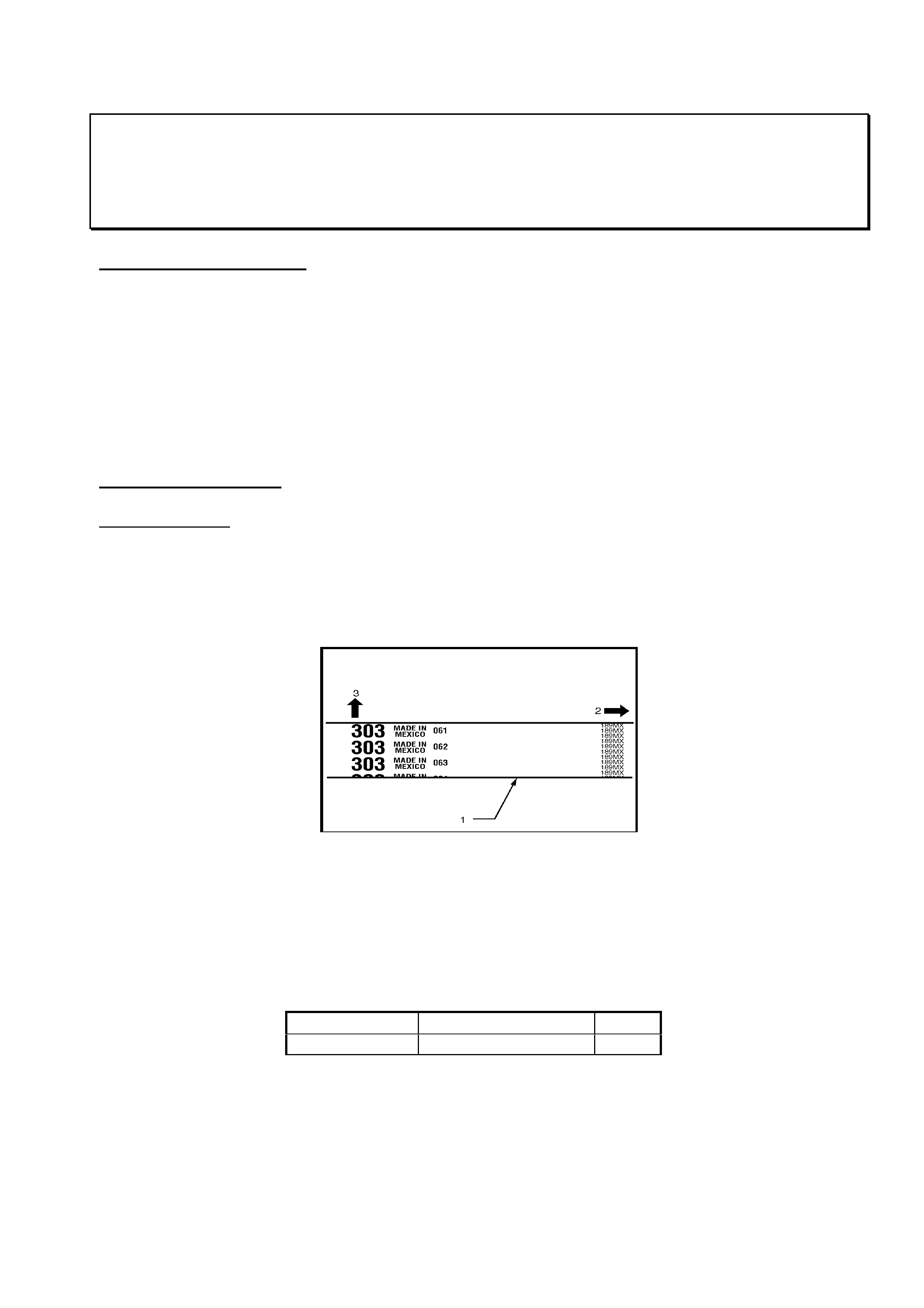
Belt Identification
The correct belt can be identified by the number 303 as shown in the diagram below. The previous
belt was marked with T200; this belt has the incorrect installation alignment marks and should not
be used.
Figure 1
LEGEND
(1) Timing Belt.
(2) Engine Rotation Direction.
(3) Cylinder Head Side.
All belts with the incorrect installation alignment mark have been removed from HSPO stock.
Part No.: Description: Qty:
8971363210 Timing Belt (303) 1

HOLDEN SERVICE TECHLINE ______________________________________________________________ APRIL 2001
26
SERVICE RECTIFICATION
SUMMARY
The procedure included in this Techline can be summarised into the following simple points. The
purpose of this summary is to provide an overview of important points required to fully understand the
following procedure.
- The V6 engine fitted to Rodeo, Jackaroo and Frontera from 98 has a cam drive system where the
reduction is partly obtained through the timing belt pulleys and partly through the cam drive gear
located in the cylinder head. The two ratios combined form a reduction ratio of 2:1.
- Due to the two-stage reduction three timing reference points are required when setting the cam
timing. They are the (1) crankshaft (2) camshaft belt pulleys (3) actual camshaft position. The
timing marks on the belt pulleys will line up every 3 crankshaft rotation while the timing marks and
actual camshaft positions will only line up every 6 crankshaft rotations.
PREPARATION PROCEDURE
Remove all components required to gain access to the timing belt as listed below:
- Battery ground;
- Air intake assembly;
- Upper radiator fan shroud;
- Serpentine belt;
- Cooling fan, cooling fan clutch and bracket
- Serpentine belt tensioner and idler pulley assemblies;
- Power steering pump assembly;
- Crankshaft pulley;
- Timing belt covers, right side first.
NOTE: If the timing belt is being replaced as part of regular servicing and there is no reason to
suspect a fault with the cam timing, follow the ‘Belt Service’ procedure.
If the timing position of the engine is unknown or in doubt ie. broken timing belt or head
removal, follow the ‘Unknown Cam Timing’ procedure.
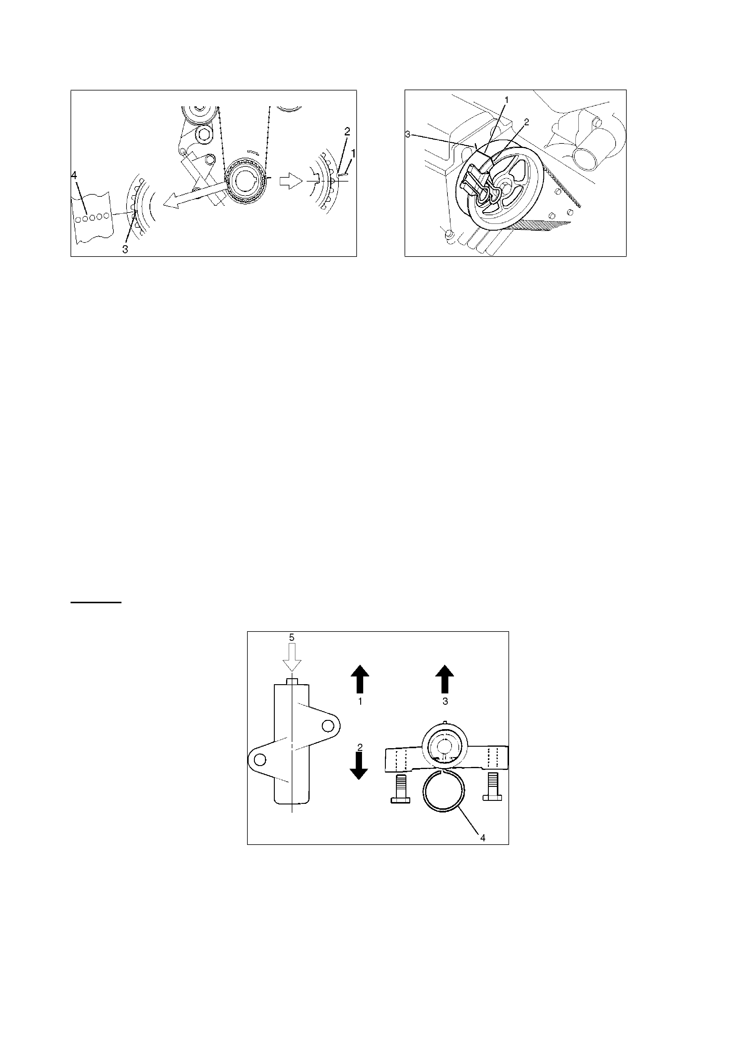
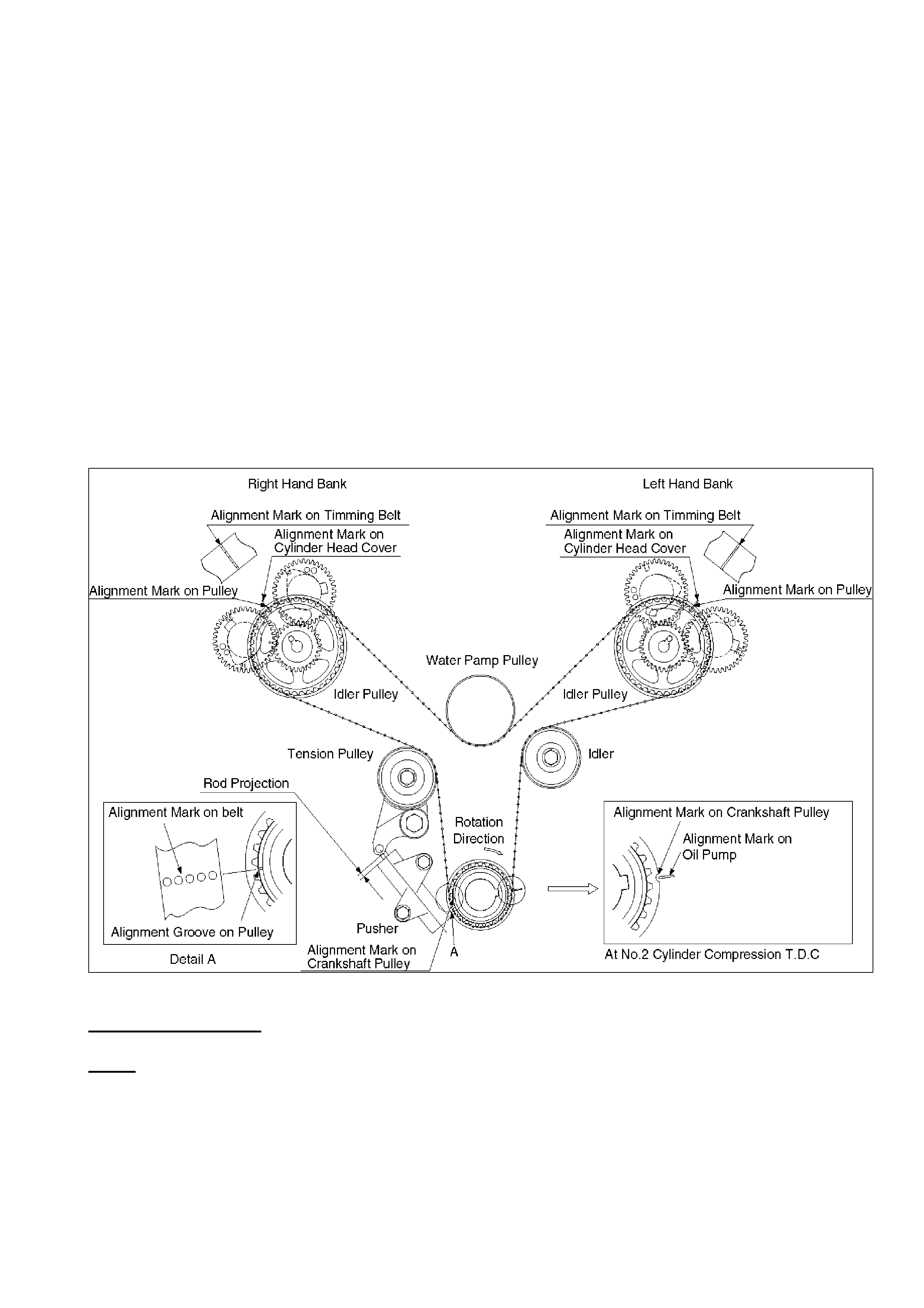
PROCEDURE 1 - BELT SERVICE
- Rotate the engine until the notch on the crankshaft timing pulley aligns with the mark on the oil
pump housing (TDC Cyl #2, Figure 2). At the same time, the painted marks on each of the
camshaft pulleys must align with the marks on the cylinder head covers. Refer Figure 3. This
should require no more than 3 rotations of the crankshaft. The marks on the belt will not line up
with the timing marks.
HOLDEN SERVICE TECHLINE ______________________________________________________________ APRIL 2001
27
Figure 2 (Crankshaft Alignment) Figure 3 (Camshaft Alignment, mirror
image for left side)
Legend Legend
(1) Mark on oil pump (TDC Cyl #2) (1) Alignment mark on timing belt (for
(2) Notch on crankshaft timing pulley. belt installation only).
(3) Alignment mark on crankshaft timing pulley (2) Alignment mark on camshaft timing pulley
(for belt installation only). (3) Alignment mark on head cover.
(4) crankshaft alignment mark on timing belt
(for belt installation only).
- Remove the timing belt. While removing the belt be sure that the camshaft pulleys do not move.
If a camshaft pulley should move for any reason it must returned to exactly the same position ie. if
the pulley should move in a clockwise direction it must be returned to the same position by
rotating the pulley in the anti-clockwise direction and vice versa.
The camshaft will be in different position if rotated forward two revolutions. If the position of the
camshafts becomes unknown for any reason the ‘Unknown Cam Timing Procedure’ should be
used to complete the timing belt installation.
- Remove the timing belt pusher (tensioner).
Caution: To prevent air entering the oil chamber the pusher must be stored with the rod
facing upward.
Figure 4
Legend
(1) Up Side.
(2) Down Side.
(3) Direction for Installation (Engine Side).
(4) Apply force of 980Nm (220Ib) to compress the pusher (tensioner).

HOLDEN SERVICE TECHLINE ______________________________________________________________ APRIL 2001
28
BELT INSTALLATION
NOTE:
Do not bend or twist the belt otherwise, its core could be damaged. The belt should not be
bent to a radius of less than 30mm.
Do not allow oil or other chemical substances to come in contact with the belt.
Do not attempt to pry or stretch the timing belt during installation.
Store the timing belt in a cool dark place. Never expose the belt to direct sunlight or
excessive heat while in storage.
- Install the new timing belt in the direction shown in Figure 1. When installed correctly you wil be
able to read the writing on the belt during installation as seen from the front of the engine.
- Install the timing belt on the crankshaft first; align the white dotted line on the timing belt with the
alignment mark on the crankshaft pulley, refer Figure 2. Secure the belt onto the pulley using a
‘bulldog’ clip.
- Align the appropriate solid white lines on the timing belt with the respective camshaft pulleys and
secure with ‘bulldog’ clips, refer Figure 3. You may need to slightly rotate (one tooth) the L/H
camshaft pulley anticlockwise to assist with fitting the belt to the camshaft pulley, once fitted the
timing marks can then be realigned.
- Compress the belt pusher slowly in a press, be sure to maintain a light resistance on the press
handle so the hydraulic pusher is not damaged. Install an appropriate locking pin into the pusher
eg. meat skewer.
- Rotate the crank clockwise to obtain maximum belt slack for fitting the pusher.
- Install the pusher and release the locking pin.
- Remove ‘Bulldog’ clips from the crankshaft and camshaft pulleys.
NOTE: The belt installation procedure above is the same procedure as that used since 1992 on V6
Jackaroo.
- Install the crankshaft pulley and rotate the crankshaft 3 complete revolutions until the timing notch
on the crankshaft pulley again aligns with the mark on the oil pump housing, the timing marks on
the camshaft pulleys should realign with the marks on the head covers.
NOTE: The marks on the timing belt are for installation purposes only and will not realign
with the cam timing marks.
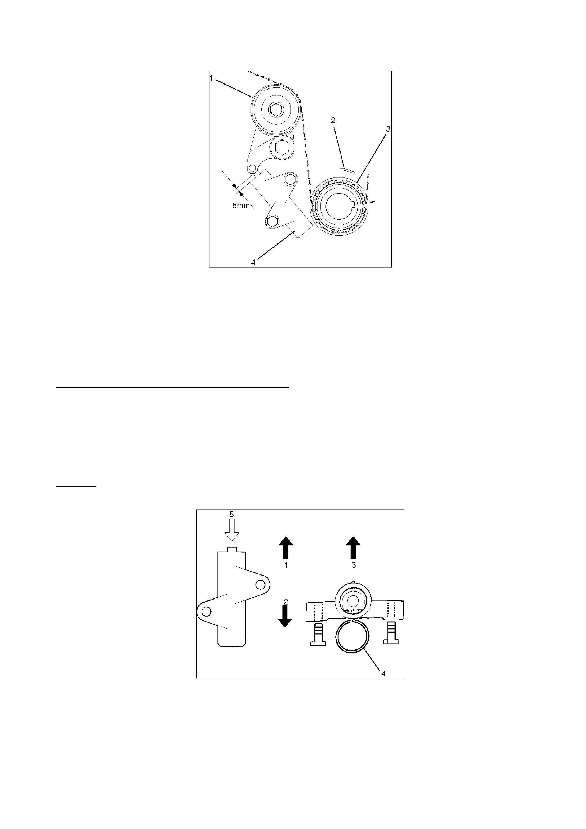
- Check that the rod projection on the timing belt tensioner is approximately 5mm (Refer Figure 5).
HOLDEN SERVICE TECHLINE ______________________________________________________________ APRIL 2001
29
Figure. 5
LEGEND
(1) Tensioner Pulley
(2) Crankshaft Direction of Rotation
(3) Crankshaft Pulley
(4) Pusher Assembly “Tensioner”
- Re-assemble the engine in the reverse order as described in the ‘Preparation Procedure’.
PROCEDURE 2 - UNKNOWN CAM TIMING
- Gain access to the front of the engine by using the ‘Preparation Procedure’ as described above.
- Remove broken belt or re-install repaired cylinder head as required. Be sure to remove any
foreign material form around the timing belt drive area.
- Remove the timing belt pusher (tensioner).
Caution: To prevent air entering the oil chamber the pusher must be stored with the rod
facing upward.
Figure 6
Legend
(1) Up Side. (2) Down Side.
(3) Direction for Installation (Engine Side). (4) Lock Pin
(5) Apply force of 980Nm (220Ib) to compress the pusher (tensioner).
HOLDEN SERVICE TECHLINE ______________________________________________________________ APRIL 2001
30
- Remove cylinder head covers.
- Align the timing marks as shown in Figure 7 noting the following 3 points.
- Align the notch on the crankshaft timing pulley with the mark on the oil pump housing (TDC
Cyl#2).
- Rotate the right side camshaft pulley until the timing mark is at the 12 o’clock position relative to
the cylinder head mounting surface (Refer Figure 7). While in this position the cam lobes for
cylinder #1 (directly behind the cam pulley) must be in the position shown in Figure. 7. Up to four
rotations of the cam pulley may be required to achieve correct alignment.
- Rotate the left side camshaft pulley until the timing mark is at the 12 o’clock position relative to
the cylinder head mounting surface (Refer Figure 7). While in this position the cam lobes for
cylinder #2 (directly behind the cam pulley) must be in the position shown in Figure. 7 (Firing). Up
to four rotations of the cam pulley may be required to achieve correct alignment.
Figure. 7
BELT INSTALLATION
NOTE:
Do not bend or twist the belt otherwise, its core could be damaged. The belt should not be
bent to a radius of less than 30mm.
Do not allow oil or other chemical substances to come in contact with the belt.
Do not attempt to pry or stretch the timing belt during installation.
HOLDEN SERVICE TECHLINE ______________________________________________________________ APRIL 2001
31
Store the timing belt in a cool dark place. Never expose the to direct sunlight or excessive
heat while in storage.
- Install the new timing belt in the direction shown in Figure 1. You must be able to read the writing
on the belt during installation as seen from the front of the engine.
- Install the timing belt on the crankshaft first; align the white dotted line on the timing belt with the
alignment mark on the crankshaft pulley, refer Figure 7. Secure the belt onto the pulley using a
‘bulldog’ clip.
- Align the appropriate solid white lines on the timing belt with the respective camshaft pulleys and
secure with ‘bulldog’ clips, refer (Figure 7). You may need to slightly rotate (one tooth) the L/H
camshaft pulley anticlockwise to assist with fitting the belt to the camshaft pulley, once fitted the
timing marks can then be realigned.
- Compress the belt pusher in a press, be sure to maintain a light resistance on the press handle
so the hydraulic pusher is not damaged. Install an appropriate locking pin into the pusher eg.
meat skewer.
- Rotate the crank clockwise to obtain maximum belt slack for fitting the pusher.
- Install pusher and release the locking pin.
- Remove ‘Bulldog’ clips from the crankshaft and camshaft pulleys.
NOTE: The belt installation procedure above is same procedure as that used since 1992 on V6
Jackaroo. It is the method of positioning the cams and cam pulleys that differs.
- Install the crankshaft pulley and rotate the crankshaft 6 complete revolutions. The crank timing
pulley mark, cam timing pulley marks and cam lobe positions should return to that shown in
Figure.7.
NOTE: The marks on the timing belt are for installation purposes only and will not align again
with the cam timing marks.
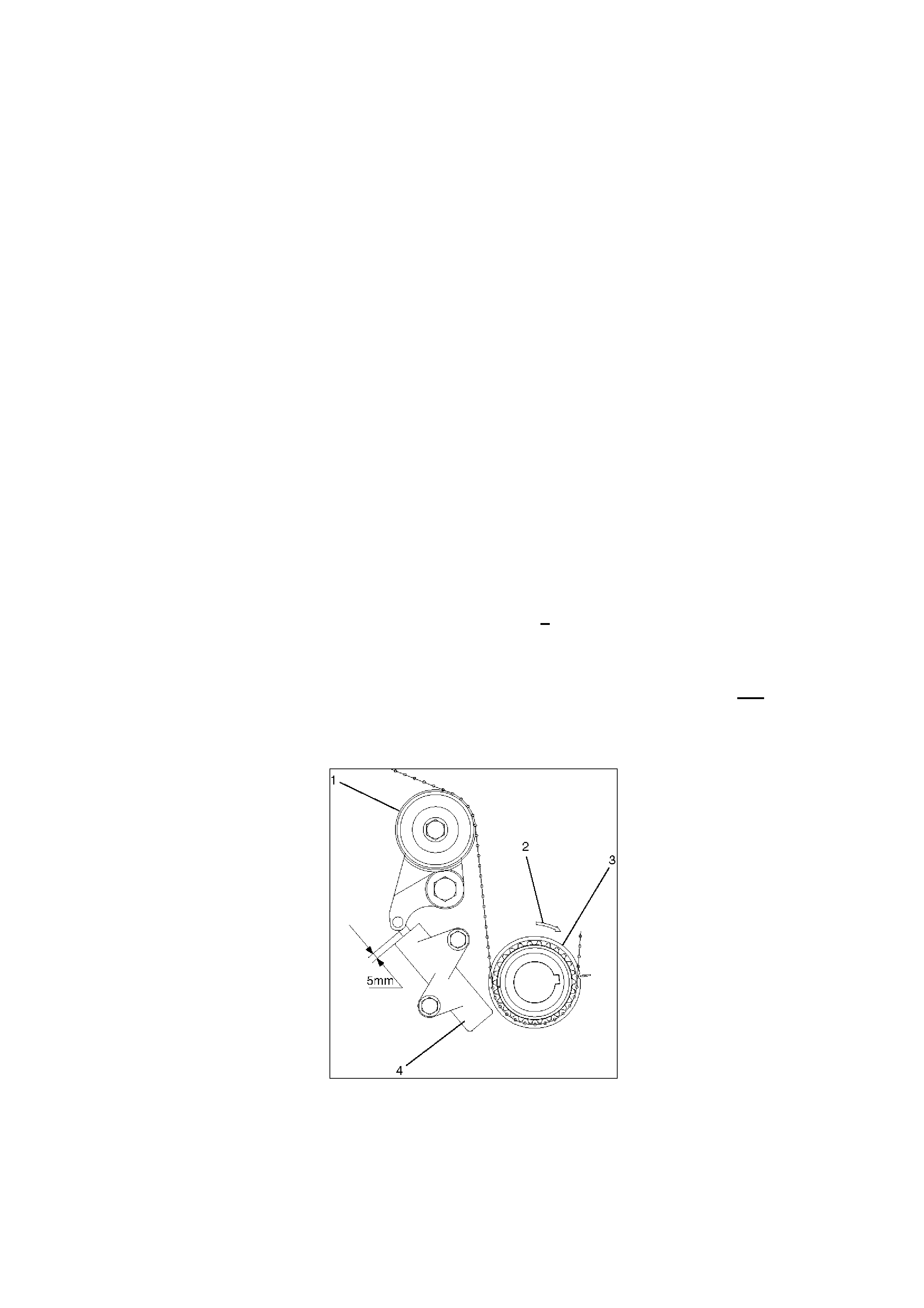
- Check that the rod projection on the timing belt tensioner is approximately 5mm (Refer Figure 8).
Figure. 8
LEGEND
(1) Tensioner Pulley
(2) Crankshaft Direction of Rotation
(3) Crankshaft Pulley

HOLDEN SERVICE TECHLINE ______________________________________________________________ APRIL 2001
32
(4) Pusher Assembly “Tensioner”
- Re-assemble the engine in the reverse order as described in the ‘Preparation Procedure’.
LC6A0401.DOC
HOLDEN SERVICE TECHLINE ________________________________________________________________ MAY 2001
14
SHOCK ABSORBER LEAKAGE
UBS JACKAROO
(GROUP 3 & 4) TL105-0301
PROBLEM DESCRIPTION
Shock absorber leaks excessive oil from between
the piston rod and seal
PRODUCTION RECTIFICATION
A Teflon bush has been added in production to
reduce the amount of lateral stress placed on the
piston rod and oil seal. The seal has also been
revised to increase service life.
ISOVIN: Build Date:
JACUBS26GY7101358 (Pet) 23/02/00
JACUBS73GY7104579 (Dies) 23/02/00
Please PIR any post - breakpoint vehicles that
exhibit a leakage condition.
TECHNICAL BACKGROUND
The following information is repeated from April
2001 Passenger Techline and although it initially
referred to passenger vehicles, it can also be
applied to light commercial vehicles as a general
reference.
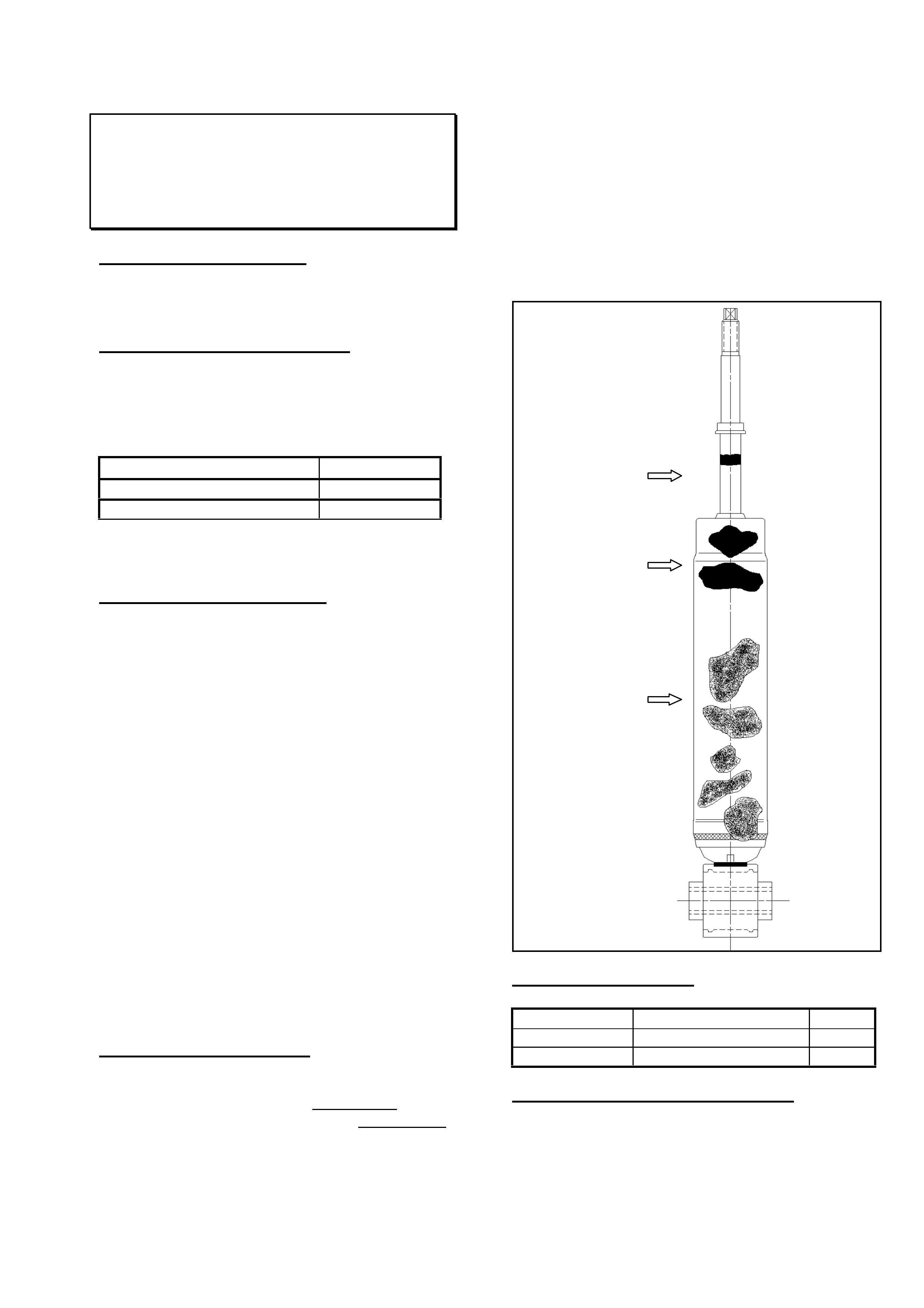
The normal operation of all shock absorbers
allows for a thin film of shock absorber oil to
adhere to the piston rod surface to allow for
lubrication of the seal during operation. In certain
operating environments this oil film becomes
contaminated with foreign matter such as road dirt
and sand. The seal is designed to exclude this
contaminated oil film in the compression stroke
and a build up of “sludge” results.
During the life of all shock absorbers this oily
“sludge” will create a film on the shock absorber
body. This film is normal and in no way
compromises the function of the shock absorber.
The criteria outlined below identifies the
acceptable conditions that may be observed when
inspecting shock absorbers at various times
during the life of the product.
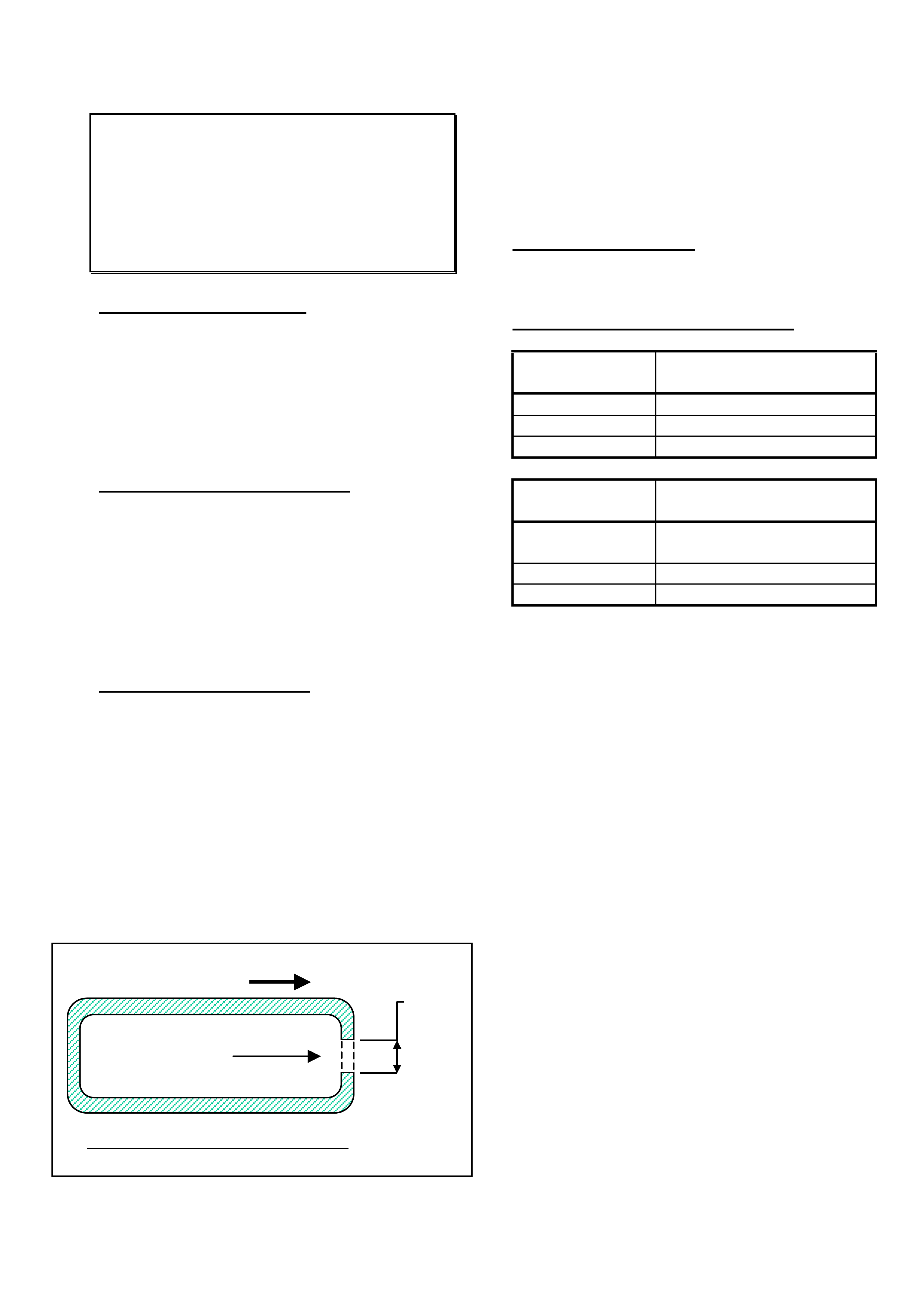
SERVICE RECTIFICATION
If a shock absorber displays worse conditions than
that shown in the drawing (ie: greater than 10mm
band of “grime” on piston rod, or greater than
40mm build up of “sludge” on body), the shock
absorber is classified as LEAKING, and should be
replaced. If the shock absorber on the other side
of the vehicle is NOT leaking, it should be left in
service.
PLEASE ALSO NOTE THAT:
In the event of a faulty shock absorber:
- the faulty unit may be replaced without replacing
a matching pair;
- faulty shock absorbers must NOT be cleaned
prior to them being returned.
PARTS INFORMATION
Part No.: Description: Qty:
8970393193 Frt Shock Absorber 1
8970438172 Rr Shock Absorber 1
WARRANTY CLAIM INFORMATION
Use existing information provided in SIP.
Oily grime build up
at end of stroke up
to 10mm wide
band
Oily “sludge”
accumulated from
normal operating
conditions to 40mm
down the body of
the shock absorber
Shock absorber body
may be discoloured
by road grease and
oil, sand and dust, but
this does not
constitute a leaking
shock absorber. In
this event the shock
absorber should be
wiped clean and
checked at the next
service

HOLDEN SERVICE TECHLINE ________________________________________________________________ MAY 2001
15
EVAPORATOR FREEZE UP
UBS JACKAROO
(GROUP 2) TL105-0201
PROBLEM DESCRIPTION
While driving with the air conditioning on for approximately two hours at highway speeds, customers
may report that the air conditioning stops working and the air flow through the vents is reduced.
Usually this occurs in areas that are experiencing humid weather. These are typical conditions that
can promote ‘evaporator freeze up’.
PRODUCTION RECTIFICATION
A revised thermistor is available, however it will not be added to production due to the low incidence.
Revised thermistors are to be fitted to vehicles on a case by case basis.
The above condition can be rectified by replacing the thermistor, a revised thermistor (refer Parts
Info. below) will cut the compressor out at approximately 1.5oC higher temperature. This
temperature difference is sufficient to prevent the air conditioning evaporator from ‘freezing up’,
while having negligible effect on the air conditioning efficiency.
SERVICE RECTIFICATION
1. Confirm the condition.
2. Recover the refrigerant.
3. Remove - The glove box
- Glove box surround
- Dash panel support
- Cooling unit assembly (disconnect harness)
4. Disassemble the evaporator case to remove the thermistor.
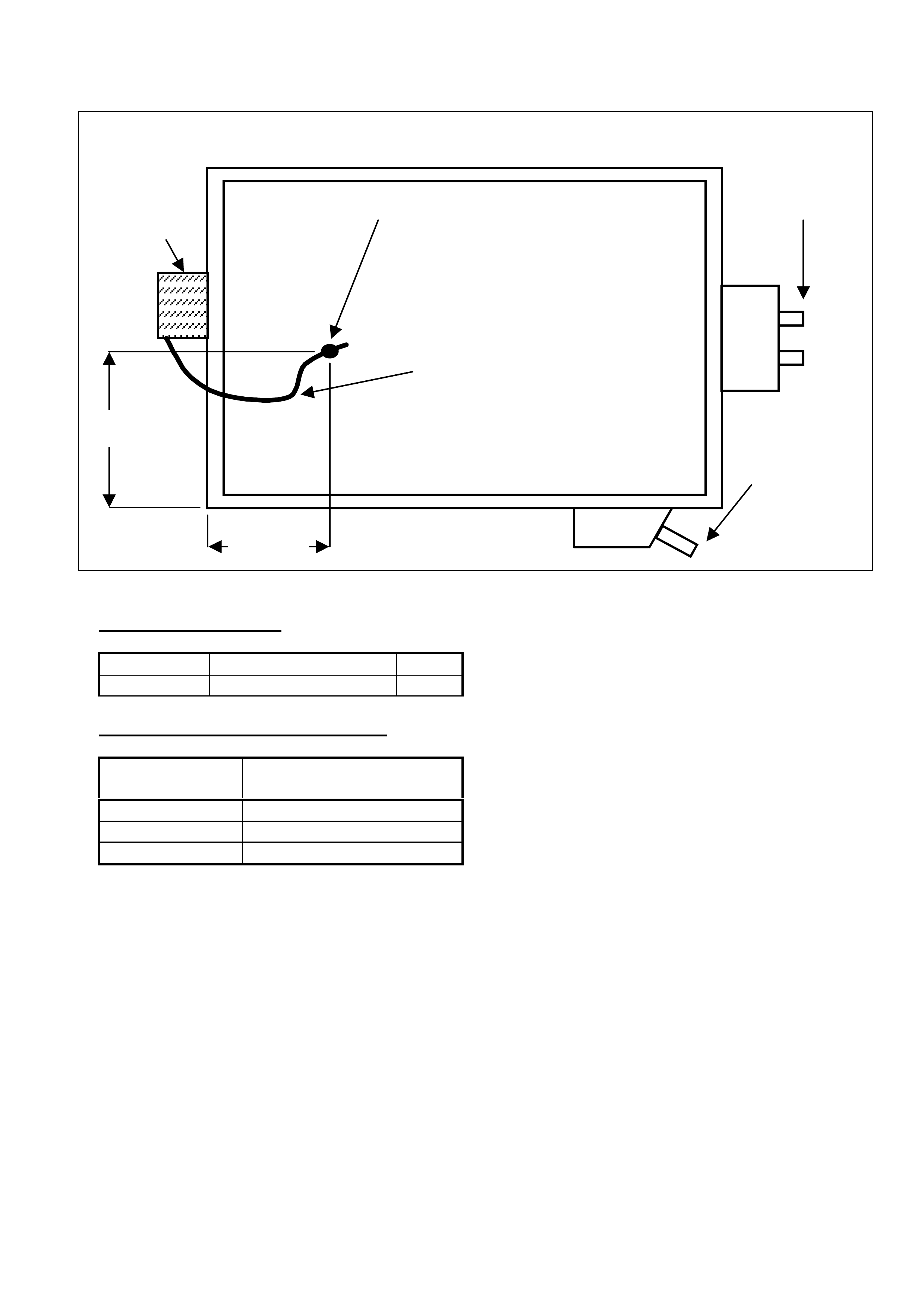
5. Fit the revised thermistor to the correct position as shown in Figure 1. Note: the diagram is
not to scale.
6. The clamp for the thermistor wire must be pushed fully between the evaporator cores. This will
prevent the thermistor wire from coming adrift, which will dramatically effect the air conditioning
operation.
7. Refit the cooling unit assembly in the reverse order as described in Step 3.
8. Charge the system with refrigerant as described in the air conditioning kit fitting instruction
(650 ± 50 gm).
9. Confirm air conditioning operation.
HOLDEN SERVICE TECHLINE ________________________________________________________________ MAY 2001
16
Figure 1
PARTS INFORMATION
Part No.: Description: Qty:
92144460 Thermistor 1
WARRANTY CLAIM INFORMATION:
Description Switch, thermostatic
control - Replace
Labour Op. No. D114000
Time 1.2 hr
Failure Code 26
Thermistor
46mm
Evaporator
Evaporator
Drain
Please ensure that
thermistor wire loops
down to prevent
condensation from forming
on the tip of the wire.
Clamp must be pushed fully into
the evaporator to maintain the
correct thermistor position
Refrigerant
Lines
133mm

HOLDEN SERVICE TECHLINE _______________________________________________________________ JUNE 2001
ROUGH RUNNING AND HESITATION
TF RODEO (V6 MANUAL WITH
APPROVED PARNELL LP GAS
SYSTEM FITTED)
(GROUP 6C) TL166-6C01 LCV
PROBLEM DESCRIPTION
After operating the vehicle on LPG for an
extended period, then switching to petrol, the
vehicle may run rough and hesitate under
acceleration.
Further investigation with Tech 2 will show
that the fuel trim cells have learnt fully lean
and are extremely slow to re-learn. The re-
learning process may take 1 tank (approx.) of
fuel.
This condition is the result of making
common the M/T and A/T VEHICLE ECU.
The production change occurred with the
2000 MY changes therefore, only vehicles
after the VINs listed are affected.
JAATF*25HY7100000 JAPAN Built
MPATF*HY710000000 THAILAND Built.
* Can be either S or R
Vehicle’s with a W (‘98’) or X (‘99’) in the
position Y (‘00’) highlighted above will not be
affected.
The condition is rectified by replacing the
CLS (Closed Loop System) controller of
the gas system. The revised controller has
been designed to suit the production
changes made to VEHICLE ECU.
PROBLEM RECTIFICATION
Inspect the CLS controller located behind the
RHS kick panel trim. Confirm that the
revised controller has not previously been
fitted. The earlier part has the part code
RODV66.
Revised Part
Part Code Description: Qty:
RODV67 CLS 2000 Controller 1
Parts can either be fitted by a Holden Dealer
or, your Parnell Authorised Service Agent.
Full instructions for replacing the CLS
controller are provided with the part.
PARTS INFORMATION
Parts must be ordered directly from Parnell
LP Gas Systems on 1800 679 985.
Hint Obtain warranty authorisation for any
labour charges from Parnell while ordering
the part
Ensure that you have the LPG Kit compliance
number (found on firewall in engine bay), the
vehicles registration and the odometer
reading, prior to ordering the part as this will
be required prior to the component being
despatched.
The old controller is to be returned to Parnell
within seven (7) days. Controllers that are not
returned will be invoiced to the respective
dealer.
All stock of new kits supplied by Parnell has
the revised controller included.
WARRANTY INFORMATION
Please discuss labour reimbursement with
Parnell when ordering the revised part
HOLDEN SERVICE TECHLINE ____________________________________________________________ JULY 2001
12
TURBO (SHAFT) FAILURE
UBS JACKAROO with 4JX1 DIESEL
ENGINE
(GROUP 6A) TL107-6A01
PROBLEM DESCRIPTION
The engine loses power and emits an
abnormal amount of smoke.
PRODUCTION RECTIFICATION
A revised turbocharger assembly has been
developed - revisions include:
• increased oil supply orifice diameter at
the turbo bearing;
• high speed balancing process introduced
in production to reduce the load on turbo
shaft bearings;
• finer mesh strainer used in the primary
pump oil pick-up to prevent foreign
material damaging the oil pressure relief
valve, causing a reduction in oil pressure.
This finer strainer is a product
improvement and the existing strainer
does not require replacement when a
turbo is replaced.
PRODUCTION BREAK POINT
ISOVIN: Build Date:
JACUBS73GY7106740 July 2000
SERVICE RECTIFICATION
Where a turbocharger has failed, procure a
new turbo assembly from HSPO, and fit to
the vehicle, using the following guidelines:
When fitting a new turbo you must:
§ To prevent further bearing failures,
confirm that the injector seal rework has
been carried out on the vehicle (position
C1 on the Vehicle Service History Label -
located on the drivers A pillar, between the
door hinges). Complete the injector seal
rework if required, refer All Dealer Letter
IGM 04/00.
§ Never run the vehicle before priming
the turbo bearings with oil and, never
run the vehicle with the oil supply to
the turbo disconnected.
§ Check the oil supply to and from the turbo
before fitting the new turbo assembly.
Disable the vehicle by disconnecting the
cam sensor and check oil supply at
cranking speed. Oil flow tests are easier to
complete with the failed turbo removed.
These are approximate values to use as
a guide only. Oil viscosity, temperature,
battery condition, etc, will cause results to
vary between vehicles.
ü Oil should flow from the turbo feed pipe
within approx. 17 seconds of cranking;
ü Approximately 25ml of oil should flow
from the turbo lubrication feed pipe for
every 1 second of cranking (once the
oil flow has commenced);
ü Check the oil return from the turbo to
the crank case. When oil is poured into
the return hose it should flow freely into
the crank case.
§ Prime the turbo by adding 100ml of oil to
the turbo oil lubrication inlet. Rotate the
turbo shaft slowly by hand, this will
ensure the turbo bearings are lubricated
at initial start up.
Detailed fitting instructions for removal and
installation of the turbo unit are in LCV SIP.
Once in SIP follow the path:
§ UBS Jackaro
§ Engine – 4JX1
§ Section 6A – Engine Mechanical
§ Engine Assembly
§ Turbocharger
PARTS INFORMATION
Part No.: Description: Qty:
8972503640 Turbo Assembly 1
WARRANTY CLAIM INFORMATION
Use existing warranty information in LCV SIP
as below.
Description Turbo Asm - Replace
Labour Op. No. J586300
Time 2.2 hr
Failure Code 85
Update

HOLDEN SERVICE TECHLINE ____________________________________________________________ JULY 2001
13
CLUTCH MASTER CYLINDER
LEAKAGE
RODEO (PETROL 2.2 LITRE & DIESEL
2.8 LITRE WITH M/T)
(GROUP 7A) TL107-7A01
PROBLEM DESCRIPTION
Loss of fluid from the clutch hydraulic system
through the clutch master cylinder piston
seal.
PRODUCTION RECTIFICATION
The assembly procedure has been revised to
prevent foreign material entry that could
cause damage to the cylinder surface and
piston seals at:
ISOVIN: Build Date:
JAATFR30HY7105183 DEC 2000
JAATFR55HY7119015 DEC 2000
JAATFS55HY7120096 DEC 2000
SERVICE RECTIFICATION
Replace clutch master cylinder assembly
once the leakage has been confirmed. Refer
to the applicable workshop manual for fitting,
adjusting and bleeding procedures.
PARTS INFORMATION
Part No.: Description: Qty:
8972010070 Clutch Master Cyl. 1
This part is applicable to all Rodeos with a
Diesel or Petrol 4 Cylinder engine produced
after 1988.
WARRANTY CLAIM INFORMATION
Use existing information in LCV SIP as
below:
Description Cylinder - Clutch Master,
Replace
Labour Op. No. K060000
Time 0.4
Failure Code 42
TAS CASE CLOSURES
ALL
(GROUP OB) TL107-OB01
PROBLEM DESCRIPTION
TAS personnel are concerned about a
number of Dealerships that are not making
an effort to close TAS cases, even after
repeated requests from TAS, via faxes and
phone calls.
Dealerships enlisting the assistance of TAS
are aware – via the TAS Procedures Manual
issued to dealerships - that Holden expects
TAS cases are updated or closed within a 30
day period.
This update or closure of cases is important,
not only to assist dealerships during
communications with TAS and the
dealership’s Aftersales District Managers, but
is also a vital source of stored information to
assist other dealerships who call for
information on similar problems.
The TAS Procedures Manual has been
provided to each dealership. This is a guide
to using the TAS system and allows service
departments to manage TAS cases within
their dealerships. If you are unsure of how to
use this manual or do not have a copy then
please contact TAS for direction in obtaining
one of these useful manuals.
Service Managers: Please ensure the TAS
Procedures Manual is readily available to
your Foreman and others who may be prime
TAS contacts – as there are various forms
and procedures that will be referred to by
TAS during calls.
Please Also Note:
TAS personnel will draw your attention to
your ‘open’ (non-closed) cases when you call
– please assist them in updating or closing
your outstanding cases AS SOON AS
POSSIBLE.
HOLDEN SERVICE TECHLINE ____________________________________________________________ AUGUST 2001
10
INJECTOR MISFIRE – INCORRECT
SEALANT USAGE
UBS with 4JX1TC Engine
(GROUP 6M) TL108-6M01
PROBLEM DESCRIPTION
Several instances have occurred where
technicians have been applying NYOGEL
sealant to the injector harness connectors of
the 4JX1TC diesel engine. This has resulted
in the injectors mis-firing when the engine is
placed under a medium to high load
condition.
IGM Product Campaign Bulletin 98-Z-01
advised dealers to lubricate the 4JX1 diesel
Crankshaft Position (CKP) Sensor connector
with “NYOGEL” - this is the only current
use for this sealant, and any other usage
of this sealant will be specified in future
bulletins.
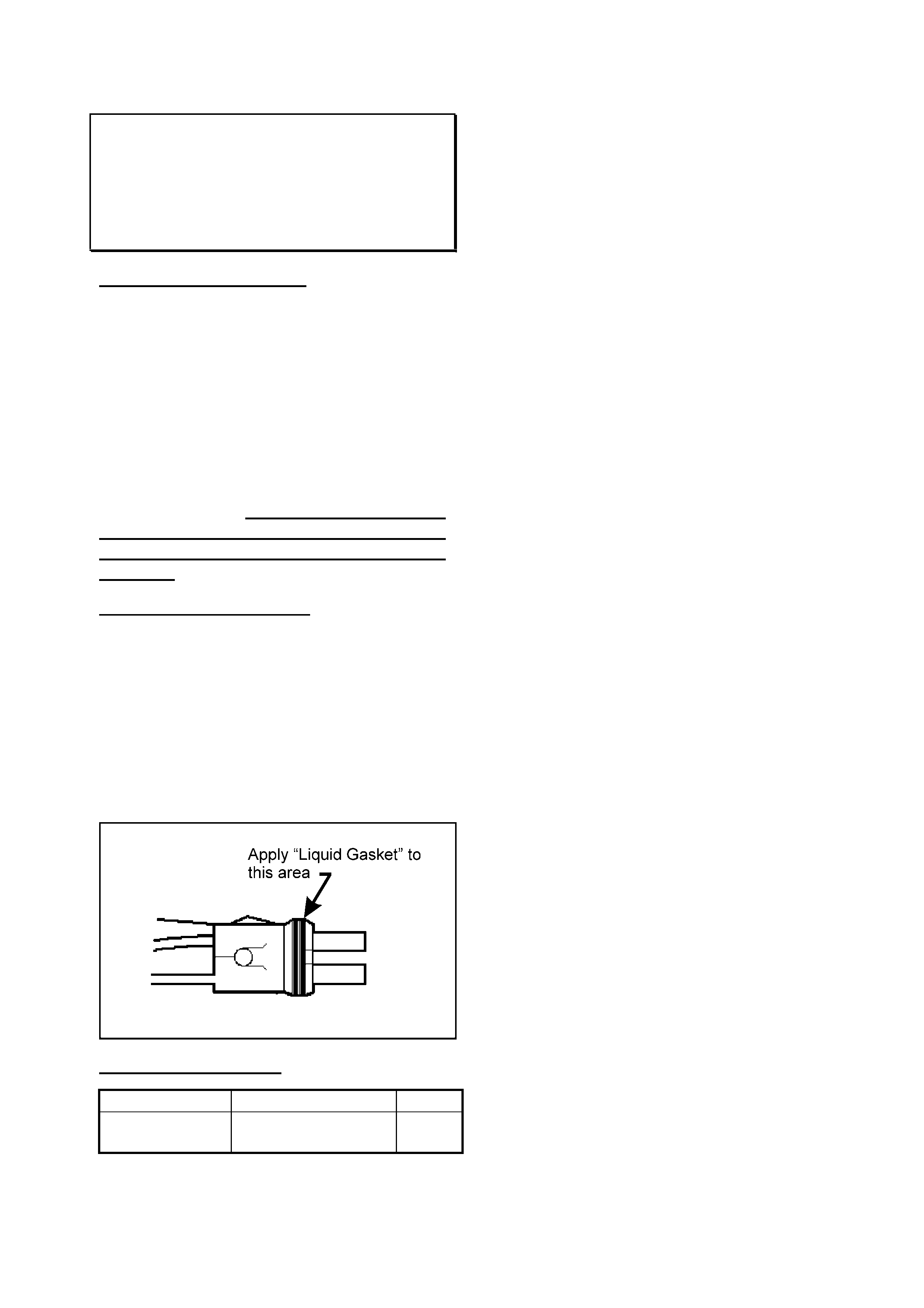
SERVICE RECTIFICATION
Technicians are advised that a thin film of
"Sealant - Liquid Gasket", Part No.
0882600080A should be applied to the
OUTER surface of the neoprene connector
sealing ring as shown in the illustration
below.
Under no circumstances must sealant be
allowed to contact the harness connector
terminals.
PARTS INFORMATION
Part No.: Description: Qty:
0882600080A Sealant - Liquid
Gasket
1
HOLDEN SERVICE TECHLINE ____________________________________________________________ AUGUST 2001
11
FRONT DOOR SNIB LOCK BUTTON
SEIZURE WHEN COLD (INTERIM
MEASURE)
TF (Rodeo)
(GROUP 1) TL108-0101
PROBLEM DESCRIPTION
On cold mornings the ignition key may not
rotate to unlock the front doors.
This condition is caused by the snib lock
guide in the interior door trim interfering with
the snib button preventing the snib button
from moving.
PRODUCTION RECTIFICATION
Corrective action has not been taken in
production to prevent this condition from
occurring.
To support the need for corrective action
in production please submit a PIR on all
vehicles that exhibit this condition.
SERVICE RECTIFICATION
Use the following procedure to rectify this
condition:
1. Remove the interior door trim.
2. Remove the snib lock guide from the front
door trim.
3. Cut a small slit through the rear of the snib
lock guide. This allows the guide to move
with temperature changes.
Insert the snib lock guide into the front door
trim with the slit facing toward the rear of the
vehicle to obscure the modification.
4. Refit the interior door trim.
PARTS INFORMATION
No parts are required.
WARRANTY CLAIM INFORMATION
Description Front Door Snib Lock
Seizure – RH Side
Labour Op. No. B000150
Time 0.7 hrs.
Failure Code 52
Description Front Door Snib Lock
Seizure – LH Side
Labour Op. No. B000153
Time 0.7 hrs.
Failure Code 52
Rear Of Vehicle
Cut a slit in
the guide to
allow guide
to flex
View from top of Lock Guide
Width of
the saw
blade
HOLDEN SERVICE TECHLINE ____________________________________________________________ AUGUST 2001
12
MISFIRE OR ‘SHUNT’ SENSATION
WITH CRUISE CONTROL ENGAGED
JACKAROO DIESEL ONLY
(ACCESSORY CRUISE FITTED)
(GROUP 6C) TL108-1201
PROBLEM DESCRIPTION
Customers may report that their vehicle has a
condition similar to a miss-fire or shunt only
with the cruise control engaged. This
condition is most likely to occur in vehicles
with an automatic transmission while driving
down a hill.
Poor earthing through the cruise control
circuit causes this condition.
SERVICE RECTIFICATION
To rectify the condition replace the Drive By
Wire (DBW) module and add an extra earth
wire as instructed below:
1. Remove the screws from the glove box hinges
and remove the glove box.
2. Remove the console that surrounds the gear
selectors. Remove any wiring attached to the
console trim e.g. telephone, heated seat
switches etc.
3. Remove the three attaching screws from the
radio surround. Disconnect the cigarette lighter
and ashtray illumination wiring; remove the
radio surround (Figure 1).
Figure 1
4. Remove the seven screws and two plastic
clips from the lower dash trims on the
passenger’s side. Take care not to scratch
the dash trim when removing t he plastic clip
that faces the left hand front door; remove
the lower dash trim.
5. Remove the passenger side knee bolster
reinforcement (four bolts & four nuts).
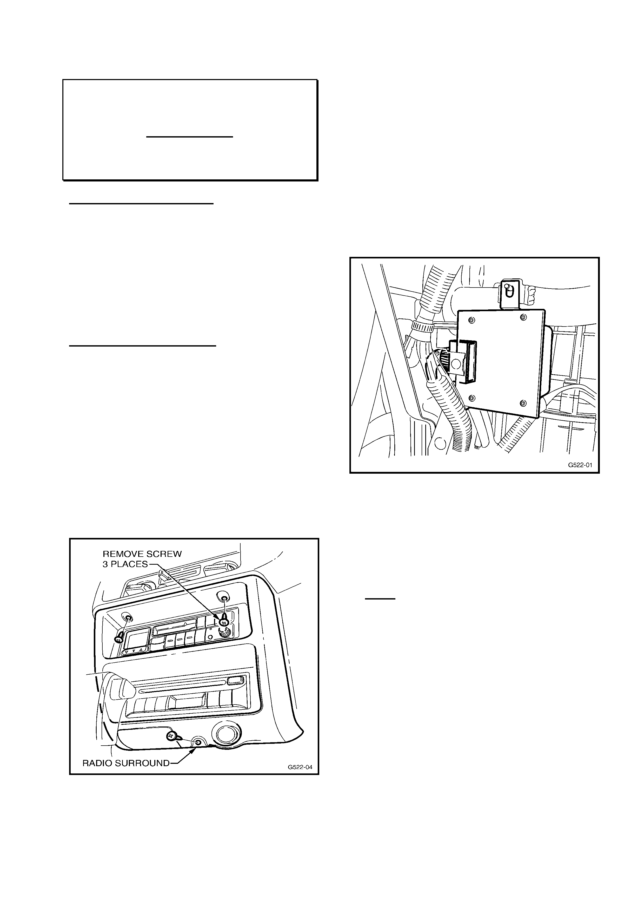
6. Remove and disconnect the existing Drive
By Wire Interface Module (Figure 2).
Figure 2.
7. Remove the module from the mounting
bracket and check the inspection date
sticker. If the module has a date sticker
prior to Oct. 2000 (or NO date sticker),
replace the DBW Module and continue to
Step 8.
Note: If the date sticker on the DBW
module is later than Oct. 2000 – the vehicle
is fitted with the latest DBW module and it
should not be replaced – do not continue
with this procedure, but contact TAS for
further diagnosis of the complaint condition.
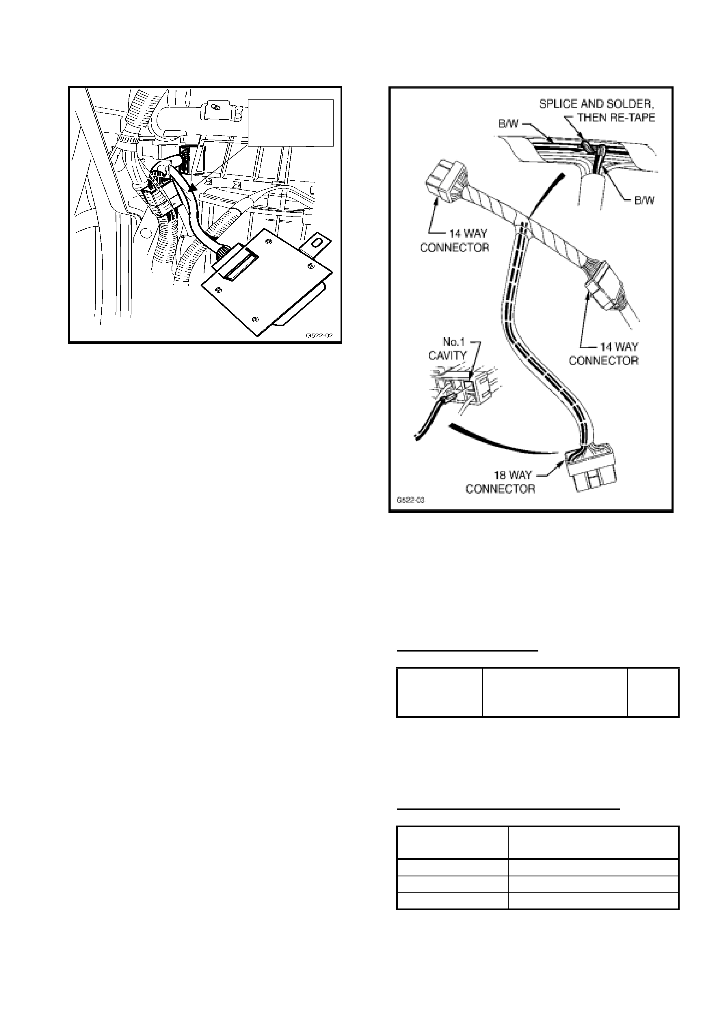
8. Disconnect the two 14 pin connectors and
the 6 pin connector of the ‘T’ shaped patch
harness; remove the harness from the
vehicle (Fig.3.).
HOLDEN SERVICE TECHLINE ____________________________________________________________ AUGUST 2001
13
Fig. 3
9. Remove the tape from the PVC tubing at the
18 way connector and the ‘T’ intersection of
the patch harness.
10. Fit the terminal of the black/white wire
(supplied with the module) to pin position 1
in the 18 pin connector (pin location is
numbered on the back of the connector).
Refer Figure 4.
11. Feed the black/white wire from the 18 pin
connector, through the PVC tubing, to the
‘T’ intersection of the patch harness.
12. Locate the black/white wire that runs
between the two 14 pin connectors, strip
sufficient insulation from this wire to make a
solder joint.
13. Cut the black/white wire from the 18 pin
connector with sufficient length to allow a
solder joint to be made with the wire
described in step 12.
14. Solder the two black/white wires at the ‘T’
intersection of the patch harness (Fig. 4).
The wire must be soldered or the cruise
control will not operate correctly. For more
details on soldering methods refer to the
VT Commodore Manual, Volume 8, 12P9 to
12P10.
Fig. 4
15. Insulate the solder joint with electrical tape
and re-tape the PVC tubing.
16. Reassemble all parts removed in the
reverse order.
PARTS INFORMATION
Part No.: Description: Qty:
92143380 DBW Module
(Earth wire included)
1
All modules and accessory kits in HSPO
stock have the revised calibration DBW
module.
WARRANTY CLAIM INFORMATION:
Description Module, Cruise Control -
Replace
Labour Op. No. R000097
Time 1.2hr
Failure Code 50
‘T’ Shaped
Harness

HOLDEN SERVICE TECHLINE _______________________________________________________SEPTEMBER, 2001
19
ENGINE OIL SPECIFICATION
JACKAROO DIESEL (4JX1 ENGINE)
(GROUP 6A) TL109-6A01
This techline supersedes all previous
information, relating to this subject,
provided in dealer letters, techlines and the
owners handbook.
This techline is to clarify and update the
required engine oil specification for the 4JX1
diesel engine as fitted to Jackaroo.
This specification should be retrospectively
applied to all vehicles, fitted with a 4JX1
engine, when being serviced by your
dealership.
Oil Specification:
Viscosity:
Preferred- 5W/30 or 10W/30
Where the preferred viscosity is not available
Use
-5W/40, 5W/50,
10W/50 or 10W/40
Classification:
API: CG-4 or CH-4
OR
ACEA: B1 or B3 (not B2)
Note: Use of the incorrect oil can cause :
• Poor cold weather starting;
• Poor idle quality;
• Excessive smoke;
• Poor performance.
This viscosity specification is consistent with
the specification outlined on the vehicle under-
bonnet stickers.
The classification on the vehicle stickers is CD
grade. This is the general export classification
specified by Isuzu and is applicable to a 5000
km oil change service interval. As Holden
specify a 10,000 km service interval the
minimum classification required is as above.
On the next page is a list of oils that meet the
required specification and are currently on the
market. The names and specification of oils
available on the market are continually
changing. To keep up to date with the latest
oils in the market please contact your oil
supplier.
……………………………..Continued next page

HOLDEN SERVICE TECHLINE _______________________________________________________SEPTEMBER, 2001
20
ENGINE OIL SPECIFICATION JACKAROO DIESEL (4JX1 ENGINE) continued….
Note: Holden does not recommend any particular brand of oil. The oils below are those within the
Holden specification range according to the information provided by the oil manufacturer. If a
particular oil manufacturer is not included in this table it does not mean that the oil manufacturer does
not produce a suitable oil. Please refer to your oil supplier to discuss oil that will meet the quoted
specification
Manufacturer
Product Name Viscosity Classification
Mobil
Mobil Delvac 1 5W/40 CH-4
Bulk Only Mobil Delvac HP-F 10W-30 CG-4
4X4 Motor Oil 10W/40 B3
Mobil 1 5W/50 B3
Mobil Delvac XP
Extra
10W/40 B3
BP
Visco 5000 5W/40 B3
Must have PLUS
in the name.
Vanellus C6 Global
Plus
10W/40 CH-4
Castrol
TXT Softec 5W/30 B3
Castrol GTX
Magnatec
10W/40 B3
FMX Magnatec 10W/30 B3
Shell
Helix Plus Eco 10 10W/30 B1
Helix Ultra 5W/40 B3
Caltex Havoline Full
Synthetic
5W/40 B3
Havoline Energy 5W/30 B1
Valvoline
Pro-Blend 10W/30 B3
Penrite
HPR5 5W/40 B3
HPR10 10W/50 B3
HOLDEN SERVICE TECHLINE___________________________________________________________OCTOBER, 2001
21
STEERING AND BODY VIBRATION
UES FRONTERA
(GROUP 01) TL0110-0103
PROBLEM DESCRIPTION
Some owners may comment on the presence
of steering wheel vibration or shimmy during
vehicle operation at medium to high speeds
Some customers may also report a knock from
the body mounts or a harsh ride.
NOTE: Depending on road conditions, some
vibration and harshness is felt through the
steering column, floor or seat when the vehicle
is driven at high speeds or in rough conditions.
POSSIBLE CAUSES:
The possible cause may be one or a
combination of the following:
1. Tyre shake and harmonic vibration
due to over-inflation or imbalance.
2. Body vibration that is transmitted
through the front body mounts
(located behind the front bumper),
due to insufficient isolation clearance
at the upper-half of the mounts.
SERVICE RECTIFICATION
Rectification for Possible Cause 1:
Test drive the vehicle to confirm the
customer’s concern.
Check if the vibration is present while driving on
a smooth surface in a straight line.
If yes inspect:
§ Tyre pressures
§ Wheel balance
§ Tyre condition for flat spots and out of
round.
Note: Tyre pressures, balance and condition
are usually not warrantable items. Wheel
balance is not warranty when the vehicle has
travelled greater than 5000 Km. Refer to the
tyre manufacturer for tyre warranty.
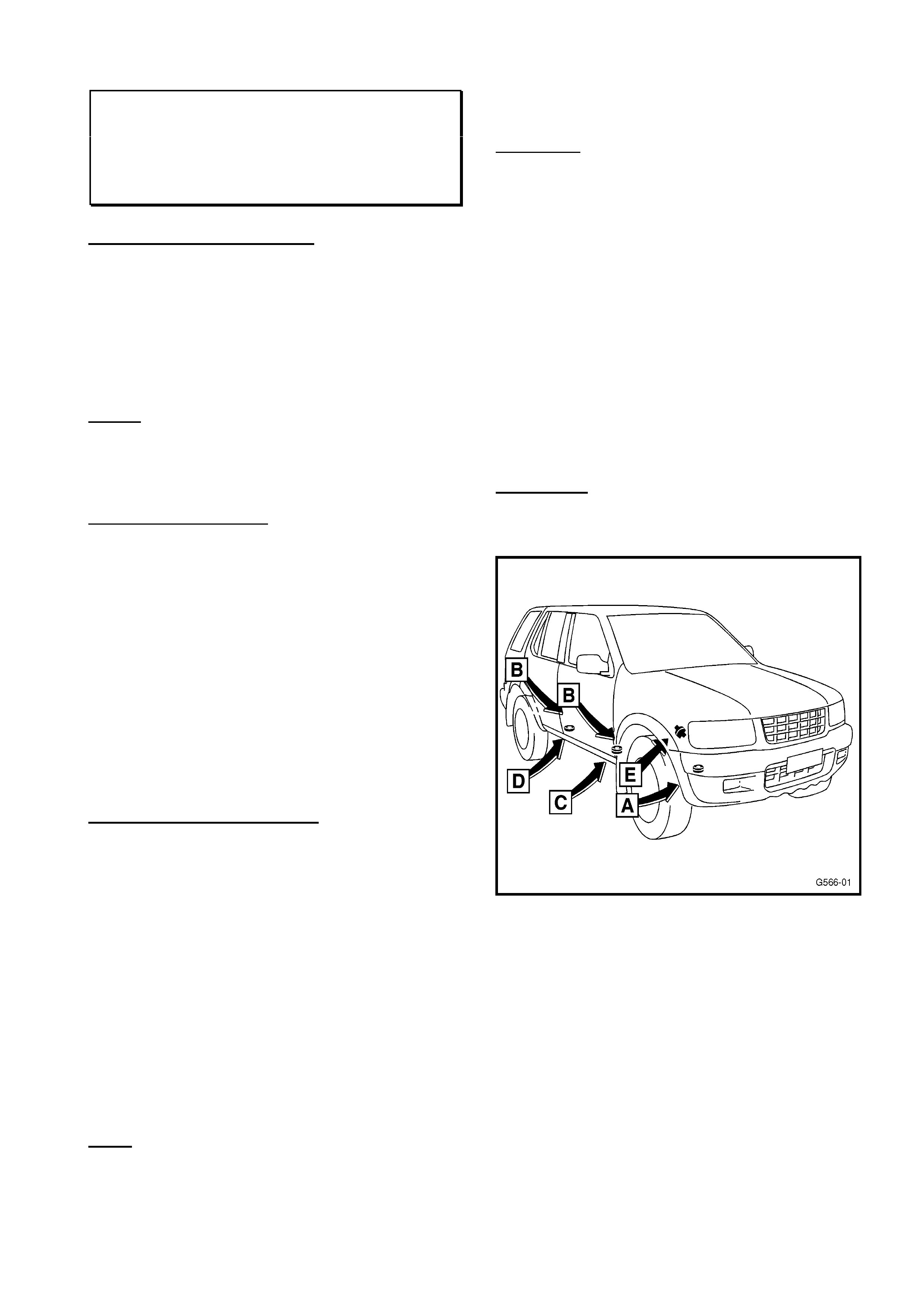
Rectification for Possible Cause 2.
Summary:
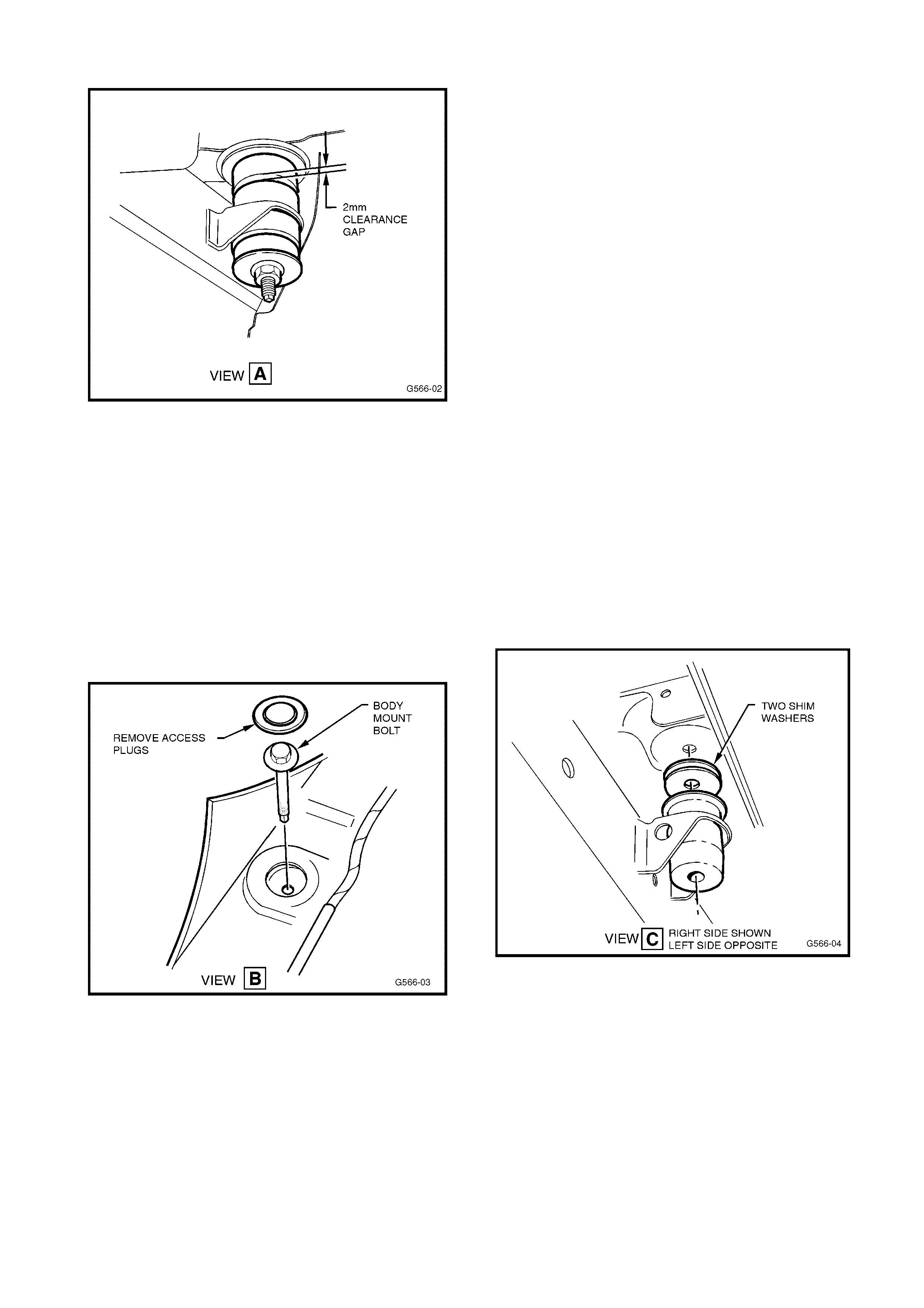
In summary, this procedure requires the mount
clearance to be inspected at position A (fig. 1)
and, if required, adjusted according to the
outlined procedure.
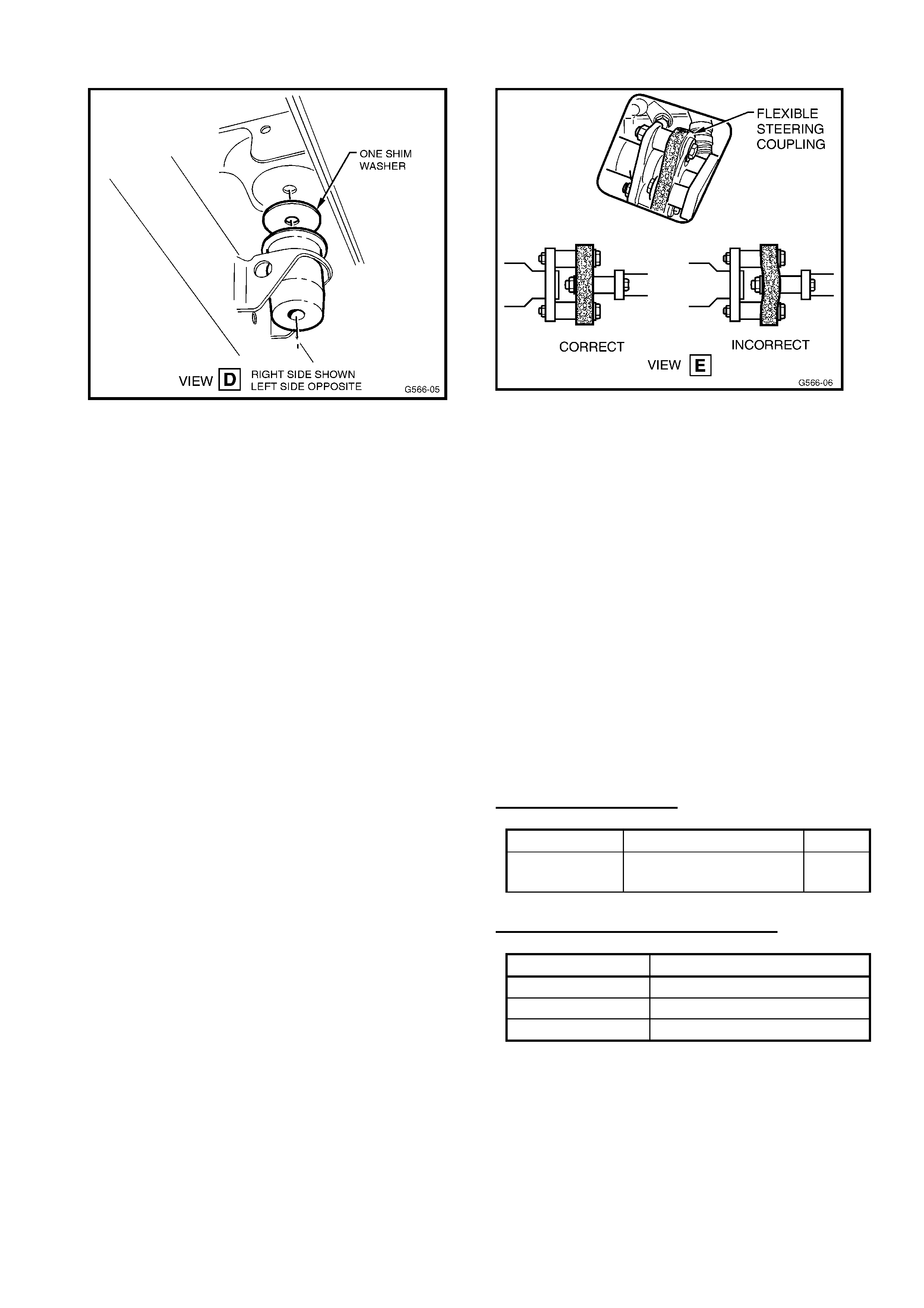
The adjustment is achieved by adding two
shims between the body mount and body at
position C and one shim at position D (refer fig.
1).
As the clearance between the chassis and body
has been adjusted, the steering coupling then
requires realigning; this is inspected from
position E (refer Fig 1).
Important: The steering coupling must be
realigned after the body mount shims have
been installed.
Fig 1.
BODY MOUNT CLEARANCE-
INSPECTION AND CORRECTION.
1. Set the vehicle down on level
ground. This is necessary for the correct
reading of body mount clearances.
2. Inspect and measure the upper
clearance gap of both left and right No. 1
body mount located behind the front
bumper (refer fig. 2). View the mount
through the wheel arch; it is not
necessary to remove the bumper.
HOLDEN SERVICE TECHLINE___________________________________________________________OCTOBER, 2001
22
Fig. 2 (Refer fig. 1 for view location)
3. If the clearance gap is 2mm or more
then the body mount is within specification
and not the cause of this condition. Where
the clearance is less than 2mm proceed to
step 4.
4. Remove the front and rear plastic
doorsill kick panels, and lift the carpet.
Remove the No. 2 and No. 3 body mount
bolt access plugs (Fig. 3). Repeat this step
for the other side.
Fig. 3 (Refer fig. 1 for view location)
5. Loosen and remove the No. 2 & No. 3
body mount bolts through the access hole
along with the washer and nut underneath
the mount. Body mount No. 2 is at view C
in fig. 1 and Body mount No. 3 is at view D
in fig. 1.
6. Loosen the No. 1 body mount nut to
the end of the bolt’s thread, DO NOT
REMOVE THE NUT FROM THE BOLT.
This will provide sufficient movement of the
cab for the shims to be installed.
7. Partially lift the body away from the
chassis using a jack and suitable lifting
adaptor to protect the panel. Jack the body
sill panel at the mid-point of the front door.
Note: Only lift the body to the amount
required to install the shims. Lifting the
body an excessive amount may damage
other vehicle components.
8. Where the customer has reported a
knock emanating from the body mount
area (floor pan) the suspected mounts
should be lubricated with silicon grease.
The metal inner sleeve should be removed
from the mount and lightly coated with
rubber grease.
9. Add 2 shims to the top of No. 2 body
mount bushing (between the body and
mount); re-install the body mount bolt
through the access hole. Refit the bottom
nut making sure to hand start the nut (refer
fig. 4).
Fig. 4 (Refer fig. 1 for view location)
10. Add 1 shim to the top of No. 3
body mount bushing (between the
body and mount), re-install the body
mount bolt through the access hole,
refit the bottom nut making sure to
hand start the nut (Refer fig. 5).
HOLDEN SERVICE TECHLINE___________________________________________________________OCTOBER, 2001
23
Fig. 5 (Refer fig. 1 for view location)
11. Lower the body onto the chassis.
12. Torque the No. 2 and No. 3 body
mounts bolt and nut to specification: 50
N.m.
13. Re-tighten and torque the No. 1 body
mount bolt and nut to specification (50
N.m).
14. Repeat steps 5 through to 13 for the
opposite side.
15. Remove any body undercoating
residue from your hands prior to refitting
any interior parts.
16. Reinstall or secure the removed
interior access plugs , carpets and trims
on both sides
17. Verify the repair by re-measuring the
upper clearance gap of the No. 1 body
mount. Specification 2 mm or greater (Ref
step 2 & 3 on previous page).
Steering Coupling Alignment (Only
required after mount adjustment)
1. Inspect the alignment of the rubber
coupling in the second steering shaft.
The coupling can be seen in view E (fig.
6).
Fig 6 (Refer fig. 1 for view location)
An example of correct and incorrect
alignment is shown in figure 6.
2. Loosen the pinch bolt of the steering
shaft, which is under the bonnet on the
upper end of the second steering shaft
assembly.
3. Using a pry bar, through the service
cut out (View E), adjust the coupling to
the correct position.
4. Re-tighten and torque the steering
shaft pinch bolt (31 N.m).
5. Confirm the steering coupling
alignment is correct.
PARTS INFORMATION
Part No.: Description: Qty:
8970379930 Washer – Body
Mounting Washer
6
WARRANTY CLAIM INFORMATION
Description Body Mount Shims
Labour Op. No. B000156
Time 1.0 hr
Failure Code 36

HOLDEN SERVICE TECHLINE___________________________________________________________OCTOBER, 2001
14
(CRACKING)
ALL ISUZU V6 ENGINES
(GROUP 6) TL0110-0601
PROBLEM DESCRIPTION
Customers may report that the engine runs
rough or makes a “hissing sound”.
The inlet manifold to head gasket may be
cracked due to stresses caused by heat
expansion and contraction.
PRODUCTION RECTIFICATION
A revised inlet manifold has been introduced
in production from the following breakpoint.
ENGINE No.
845194
SERVICE RECTIFICATION
Replace the inlet manifold gasket as per the
appropriate workshop manual.
Note: There is no need to separate the inlet
manifold into two halves unless the common
chamber gasket is suspected to be leaking.
Please PIR any post breakpoint failures on all
vehicle models fitted with this engine.
Indicate if the vehicle is fitted with an
approved LPG system (LPG Rodeo only).
PARTS INFORMATION
Part No.: Description: Qty:
8972375380 Gasket – Inlet
Manifold to
Cylinder Head
2
WARRANTY CLAIM INFORMATION
Description Gasket, Intake - Replace
Labour Op. No. J020700
Time 1.8 hr
Failure Code 42
INLET MANIFOLD GASKET LEAKS
HOLDEN SERVICE TECHLINE________________________________________________________NOVEMBER, 2001
24
INTERCOOLER DAMAGE (Servicing)
JACKAROO DIESEL (4JX1)
(GROUP 6A) TL0111- 6A02
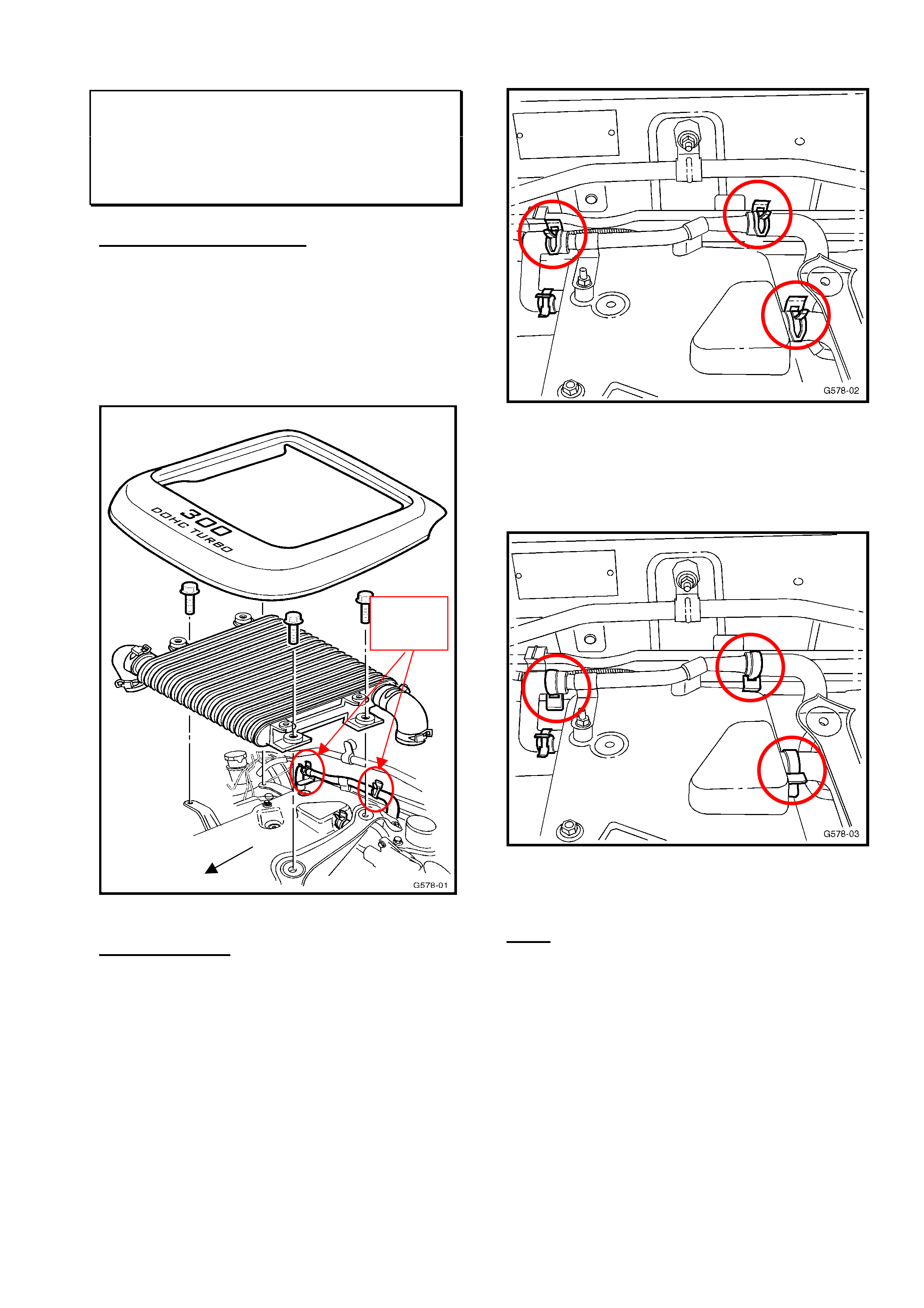
PROBLEM DESCRIPTION
Damage to the intercooler will occur when the
hose clamps for the engine ventilation system
are installed with the ears pointing upwards.
When installed in this position the hose clamp
ears will wear through the intercooler causing
an air leak.
Fig. 1
RECTIFICATION
When reinstalling the intercooler during
service or repairs, ensure the ears on all hose
clamps are facing downward as shown in
Fig. 3.
Fig 2.
INCORRECT CLAMP POSITION
Fig. 3.
CORRECT CLAMP POSITION
Note:
When repairing or servicing a diesel Jackaroo
do not place tools or parts on the intercooler
as the cooling fins could be damage.
A
rea of
Contact
Front

HOLDEN SERVICE TECHLINE________________________________________________________NOVEMBER, 2001
25
KEYLESS ENTRY REMOTE PROGRAMMING
FRONTERA
(GROUP 12) ‘UPDATE’ TL0111-1205
Programming Additional Keypads
• This procedure is carried out to program additional remote keypads into the system.
• The door opening and ignition key cycles should be committed to memory* before attempting this
procedure.
*It is extremely difficult to complete this procedure within the time constraints, unless the
sequence is memorised.
• A maximum of four keypads may be programmed into the system at any one time. Programming
a fifth keypad will result in the erasing of the first keypad programmed into the module.
NOTE: Steps 2 to 6 must be performed within 15 seconds
1 ENSURE all doors are closed, the key is in the ignition switch & the ignition is in the OFF position.
2 OPEN the driver door.
3 CYCLE the ignition switch from ‘OFF’ — ‘ON’ — ‘OFF’ 3 times.
4 CLOSE, then OPEN the driver door 2 times.
5 CYCLE the ignition switch from ‘OFF’ — ‘ON’ — ‘OFF’ 3 times, and remove key from the
ignition switch.
6 CLOSE, then OPEN the driver door 1 time.
7 CONFIRM a ‘LOCK’ — ‘UNLOCK’ response by watching the driver door snib button.
8 OPERATE the ‘LOCK’ and ‘UNLOCK’ buttons on the new keypad 3 times.
9 CONFIRM a ‘LOCK’ — ‘UNLOCK’ response by watching the driver’s door snib button.
10 OPERATE the ‘LOCK’ and ‘UNLOCK’ buttons on the new keypad 2 times.
11 CONFIRM a ‘LOCK’ — ‘UNLOCK’ response by watching the driver’s door snib.
12 The new keypad ID has been accepted.

HOLDEN SERVICE TECHLINE________________________________________________________NOVEMBER, 2001
26
NOTE:
• If steps 2 – 6 are not completed within the specified time, the programming procedure will fail.
• If the confirmation response is not received at Step 7, the programming procedure has failed.
• Should the door lock snib cycle 3 times at any stage of this procedure, the control unit has
aborted the programming sequence.
• Steps 1 to 12 must be performed for each individual keypad.
Hint: There are two likely causes for the system not confirming a ‘Lock’ – ‘Unlock’ at step 7, these
should be double checked before commencing with further diagnostics:
1. The programming sequence has not been completed within the specified time (confirm the time
with a stopwatch if unsure).
2. All doors (including tailgate) are not closed during the procedure as specified in step 1.
When performing the key programming procedure it is recommended that all electrical features be
switched off (dome light in the ‘door’ position).
CRUISE CONTROL SURGE
RODEO – (MY 2001)
(GROUP 12) TL0111-1206
PROBLEM DESCRIPTION
There have been a number of reports from dealers of surging when genuine accessory cruise
control is operated on a Model Year 2001 Rodeo.
RECTIFICATION
The cruise control module has been re-calibrated to be compatible to vehicles both pre and post MY
2001.
SERVICING
The updated parts/kit are also used when repairing or fitting a cruise control on a vehicle that is pre
MY 2001.
PARTS INFORMATION
The part number for the module and kit has not changed. All parts in dealer stock are being
returned to HSPO for re-calibration (Refer Parts Bulletin M556). Modules that have been re-
calibrated are fitted with a sticker denoting the module part number (92143384). Previously there
was no sticker on the module.
HOLDEN SERVICE TECHLINE________________________________________________________NOVEMBER, 2001
27
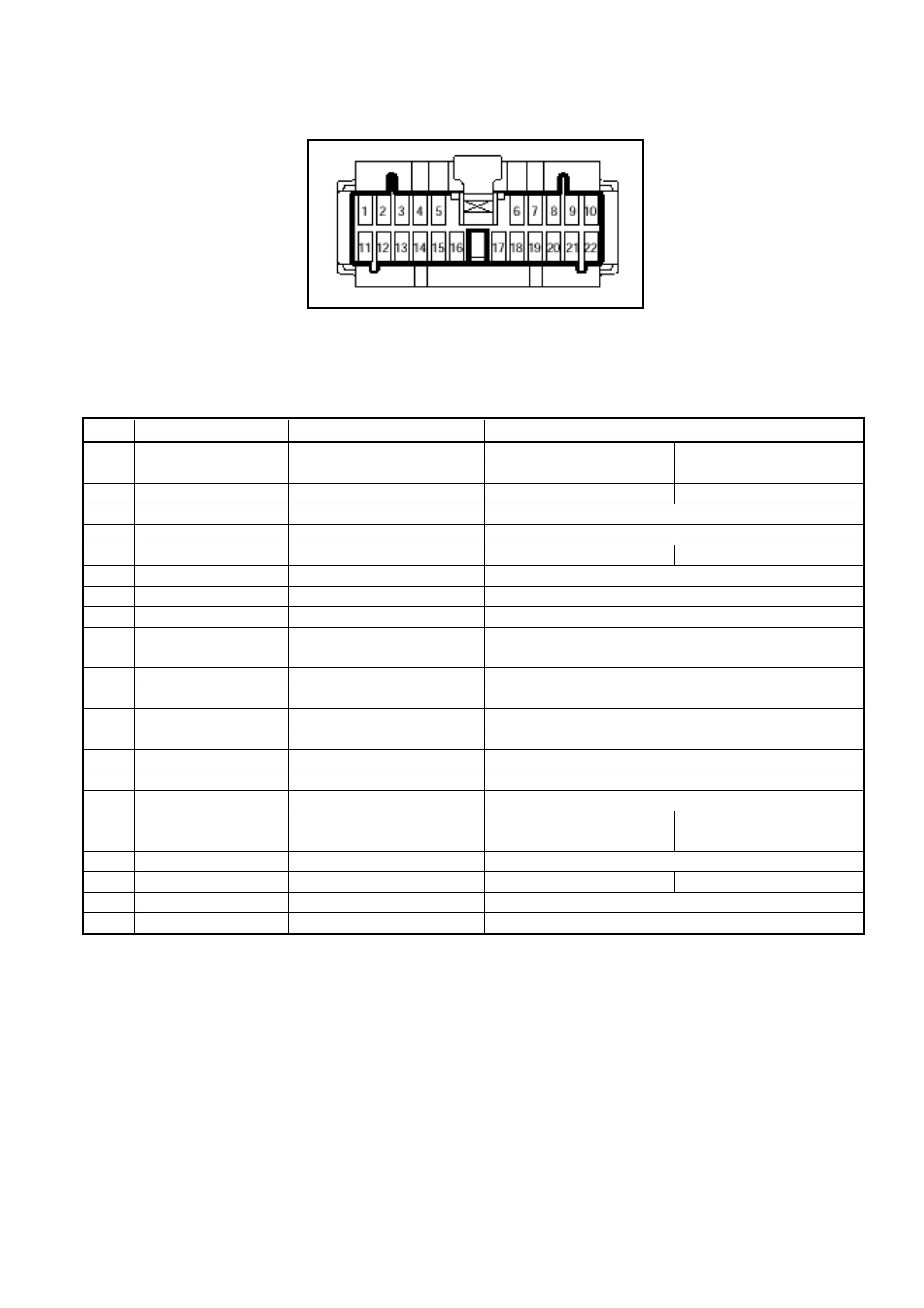
KEYLESS ENTRY - CONTROL UNIT HARNESS PINOUTS
FRONTERA (1999-2000 AND 2001-2002)
(GROUP 12) TL0111-1207
The keyless entry module harness pinouts and specifications for the 99-00 and 01-02 Frontera are
provided in this techline to assist in the diagnosis system faults.
Please refer to SIP if you are not familiar with the system of terminal numbering and connector
identification used by Isuzu.
It is recommended to use the pin location in the harness connector to identify the location of each
wire.
The keyless entry system is designed to operate with the key removed from the ignition therefore, the
following pin checks should be completed with the key removed from the ignition (except for ‘Power-
Acc’ and ‘Ignition Key Detect’).
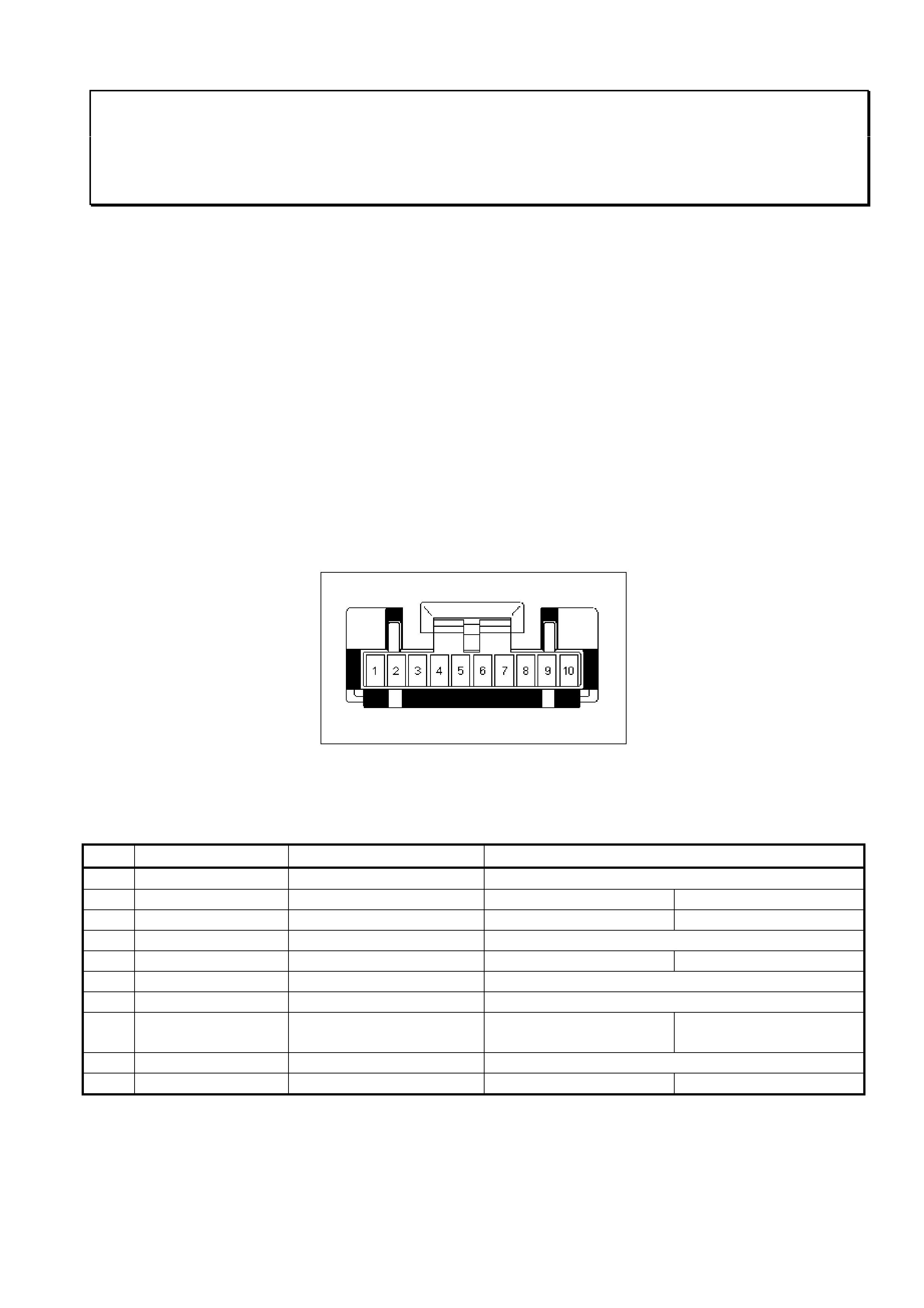
MY1999-2000 UES Keyless Entry Harness
Keyless Entry Control Unit Harness Connector
Pinout
PIN WIRE COLOUR ITEM SPECIFICATION
1 – – –
2 Red/Green Dome Lamp Doors Open: <1.5v Doors Closed: >10v
3 Light Green Tailgate Switch Tailgate Open: 0.0v Tailgate Closed: 12v
4 Light Green/Red Door 'Lock' Switch 'UNLOCK' to 'LOCK': 0.0v-1.2v-0.0v
5 Red Door Courtesy lamps Doors Open: <1.5v Doors Closed: >10v
6 Black Ground Less than 1.0 Ohm
7 Red/Blue Door 'UnLock' Switch 'LOCK' to 'UNLOCK': 0.0v-1.2v-0.0v
8 Red/Yellow
Power - Acc. (Fuse C-
2)
Ignition Key 'OFF':
0.0v
Ignition Key 'ACC':
12v
9 Green/Yellow Power (Fuse C-19) Battery voltage at all times
10 Blue Ignition Key Detect Key in lock: 12v Key out of Lock: 0.0v
HOLDEN SERVICE TECHLINE________________________________________________________NOVEMBER, 2001
28
MY2001-2002 UES Keyless Entry Harness
Keyless Entry Control Unit Harness Connector
Pinout
PIN WIRE COLOUR ITEM SPECIFICATION
1 Red Doors Doors Open: 0.0v Doors Closed: 12v
2 – – – –
3 Blue Ignition Key Detect Key in lock: 12v Key out of Lock: 0v
4 – – –
5 Light Green/Red Door 'Lock' Switch 'UNLOCK' to 'LOCK': 0.0v-1.2v-0.0v
6 Light Green Tailgate Switch Tailgate Open: 0.0v Tailgate Closed: 12v
7 – – –
8 – – –
9 – – –
10 Light
Green/White Power (Fuse C-7) Battery voltage at all times
11 – – –
12 – – –
13 – – –
14 – – –
15 Red/Blue Door 'UnLock' Switch 'LOCK' to 'UNLOCK': 0.0v-1.2v-0.0v
16 – – –
17 Black Ground Less than 1.0 Ohm
18 Brown/White Power - Acc. (Fuse C-
19) Ignition Key 'OFF': 0v Ignition Key 'ACC':
12v
19 – – –
20 Red/Green Dome Lamp Doors Open: <1.5v Doors Closed: >12v
21 Brown Turn Indicators Indicators Operating: 0.0v-12v-0.0v
22 – – –