
2
20
00
02
2
S
SE
ER
RV
VI
IC
CE
E
T
TE
EC
CH
HL
LI
IN
NE
ES
S
© 2006 GM Holden Ltd. A.B.N. 84 006 893 232
Service Department
A “HOLDEN” Product.
BRISBANE SYDNEY MELBOURNE ADELAIDE PERTH
HOLDEN SERVICE TECHLINE_________________________________________________________FEBRUARY, 2002
17
Front Trim Height Specifications
Rodeo, Frontera And Jackaroo
(GROUP 3) TL201-0301
This Service Techline supersedes the previous
Techline published in Aug 2000 as inconsistent
results could be obtained when measuring the
front t rim heights via the bum p stop clearance.
SERVICE SPECIFICATION
The following specifications reflect the
information provided in SIP.
Measuring the vehicle “trim height” rather than
“vehicle height” is recommended as there are
fewer variables.
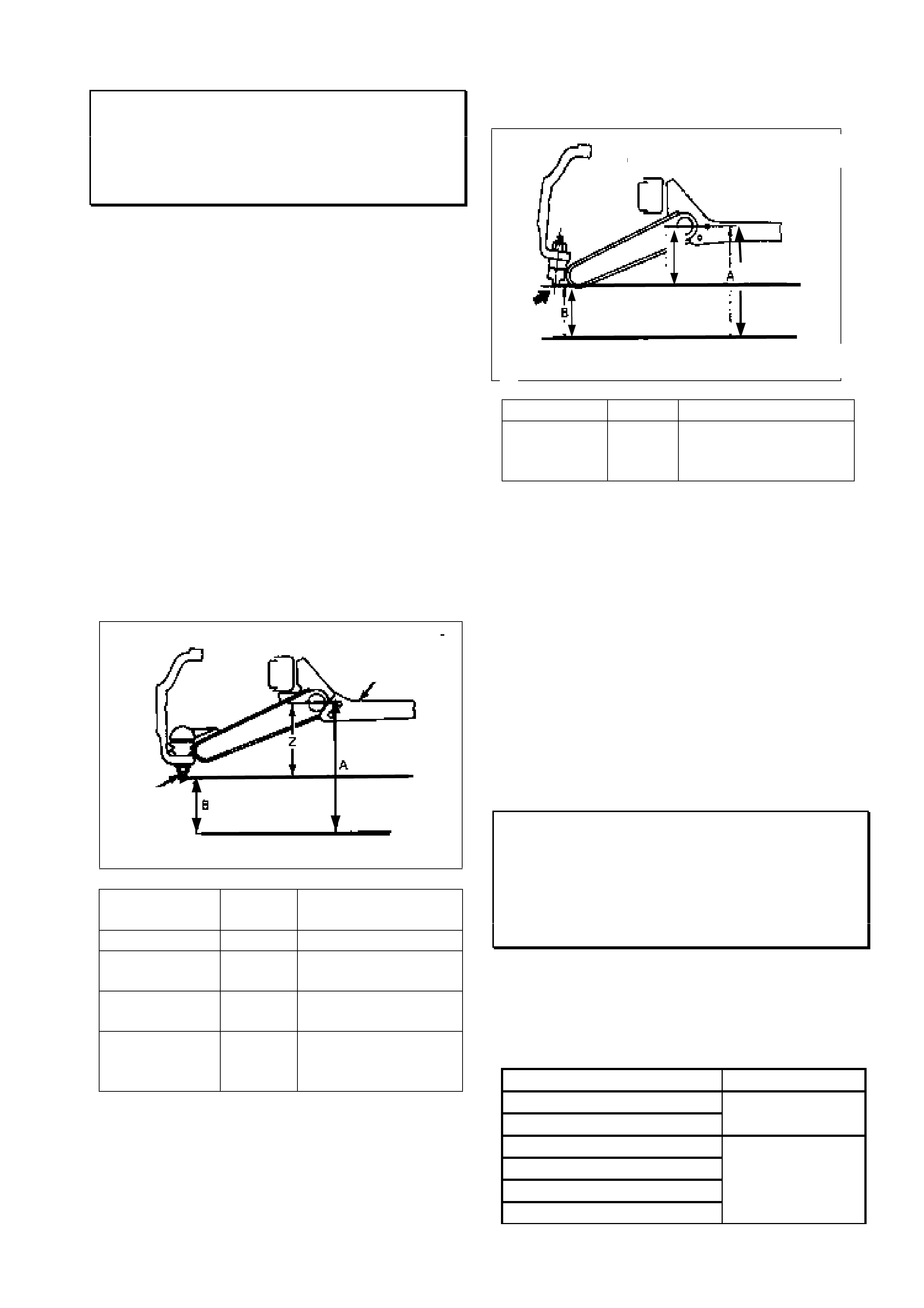
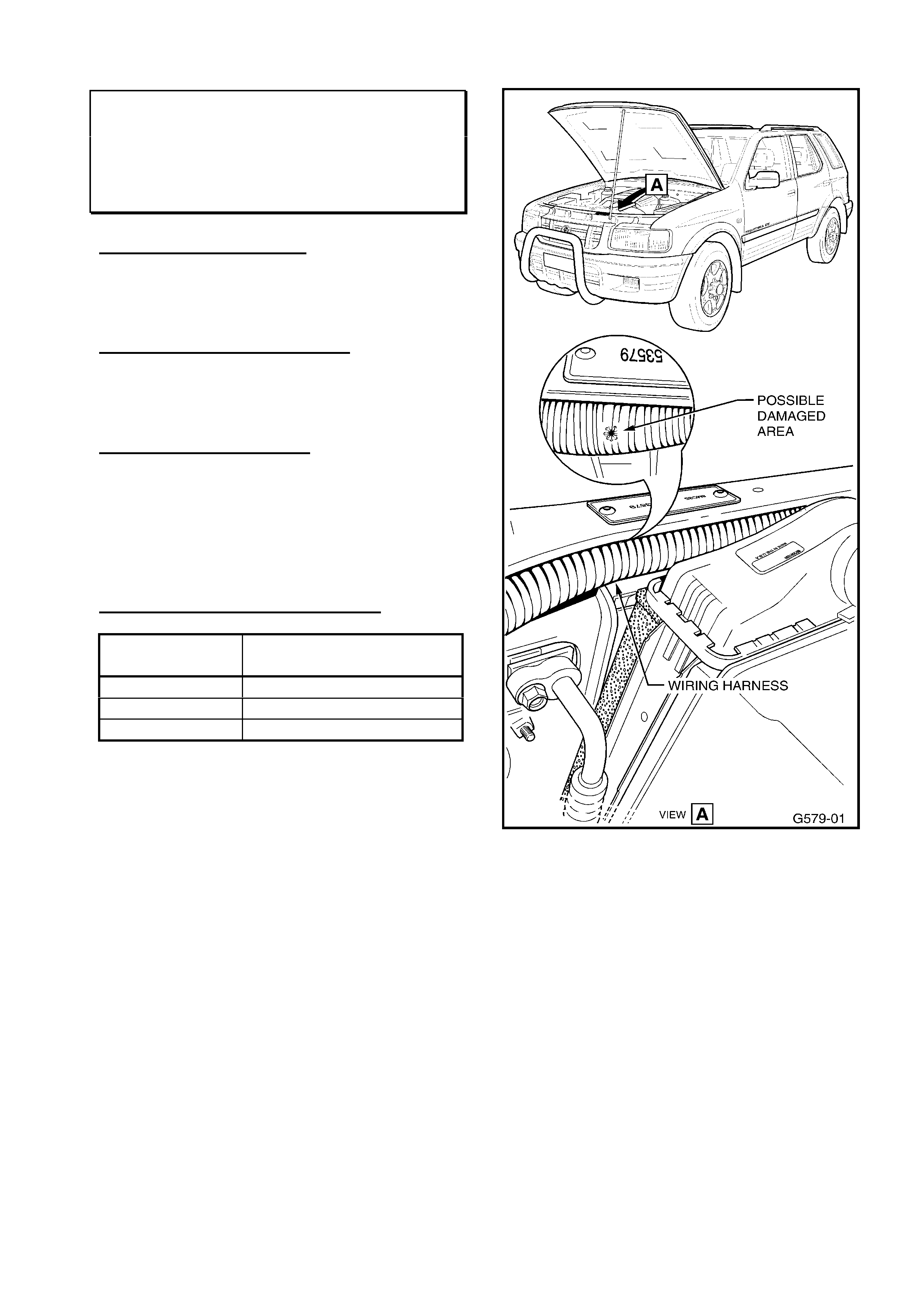
TRIM HEIGHT SPECIFICATIONS
Trim height: Z = A - B
Fig.1 refers to Jackaroo, Frontera, Rodeo 4X4
and Rodeo V6 4X2.
Model Year Trim Height
(Z)mm
Jackaroo 1992- 139 +/- 5
Frontera
(MX)
1999 - 119 +/- 5
Frontera (UT) -1999 139 (Maximum
variance of 5mm)
Rodeo 4X4
and 4X2 V6
or 4JH1-TC
All TF 130
Fig. 2 refers to Rodeo 4X2 only (Exc. V6).
Model Year Trim Height (Z) mm
Rodeo
C22NE and
4JB1-T
All TF 56
Important Points:
• The trim height must be inspected, and
adjusted if necessary, prior to adjusting
the wheel alignment (toe, camber or
caster).
• Trim height inspection and adjustment is
incorporated into the service schedule
and is checked at every service.
• The trim height is adjusted when the
vehicle is at kerb mass.
Locking Hub Grease - Breakpoints
Jackaroo & Rodeo - 4x4 With Manual
Locking Hubs
(GROUP 3) TL0201-0301
The following table provides production
breakpoints for vehicles in which the amount of
grease applied to the locking hub assemblies
has been increased by 3 grams.
ISOVIN: Build Date:
MPATFS55H2T100001
MPATFS25H2T100001 Nov 01
JAATFS55H17103411
JAATFS25H17102863
JACUBS26G27100333
JACUBS73G27100535
July 01
Lower
ball
j
oint
Crossmember
Fig. 1
Fig. 2
Measuring Point B : Centre of ball joint
B
Z A
Crossmembe
r

HOLDEN SERVICE TECHLINE_________________________________________________________FEBRUARY, 2002
18
Starting or Runni ng Problems Due To Oil
Pick Up Dama ge
Jackaroo Diesel (4JX1)
(GROUP 6M) TL0201-6M01
PROBLEM DESCRI PTION
Starting or running difficulties such as hunting,
surging or hesitation can occur if the oil pick
up, or pick up seal, for the fuel injection
system is damaged. As a result air could
enter the engine oil supplied to the diesel
injection system.
It is possible that the injection system oil pick
up has been bent to create extra room when
performing the inspection on the engine
lubrication pick up seal as described in DL
01/00 (IGM01/00).
SERVICE RECTIFICATION
When removing the oil pick up for either the
injection or lubrication system do not bend the
pick up tube or its brackets. On reinstallation
the pick up seals should checked for
serviceability and replaced where required.
Hint: Aeration of the engine oil supply to the
diesel injection system can be confirmed by
inspecting the oil exhausted from the injector
while the fault is present. The oil will appear
white or ‘milky’.
Rear Brake Squeal - Update
RODEO (4x4 and V6 4X2)
(GROUP 5) TL201-0501
This ServiceTechline is an updat e of t he article
from 2001, Issue 3, page 12. Only the break
points for Thailand built vehicles have been
added, the art icle is ot herwise identical.
PROBLEM DESCRI PTION
Excessive squeal noise emanating from rear
brakes on application.
PRODUCTION RECTIFICATION
Revised brake shoes fitted in production from:
ISOVIN: Build Date:
JAATFS25HY7103377 25/01/01
JAATFS55HY7120056 25/01/01
JAATFR25HY7108590 25/01/01
MPATFR25H1T100091 31/05/01
MPATFS55H1T100452 07/08/01
MPATFS25H1T100002 21/05/01
Note: VINs beginning with MPA are for
vehicles manufactured in Thailand. VINs
beginning with JAA are for vehicles
manufactur ed in Japan.
SERVICE RECTIFICATION
For pre-breakpoint vehicles the service fix
described below, which is the same as in
Dealer Letter IGM 13/99, can be applied.
I - GM has released a modified rear brake
shoe set (part number 5878317230) to
overcome the above complaint.
Before installation of the modified shoes the
rear brake assemblies should be de-dusted
and inspected for correct operation, if no faults
are observed the drums should be de-glazed
and the new shoes installed.
To effectively monitor the success of the
revised brake components, a PIR should be
submitted for any post-breakpoint vehicles that
exhibit squeal from the rear brakes.
PARTS INFORMATION
Part No.: Description: Qty:
5878317230 Brake Shoe Set 1
WARRANTY CLAIM I NFORMATION
Use existing Warranty Information from SIP as
shown:
Description Shoes and Lining
Labour Op. No. H025700
Time 1.2 Hr
Failure Code 40
HOLDEN SERVICE TECHLINE_________________________________________________________FEBRUARY, 2002
19
‘MIL’ Illuminated – Wiring Harness
Damage
Frontera 01 MY – 02 MY (32 Bit PCM)
(GROUP 6Y) TL0201-6Y01
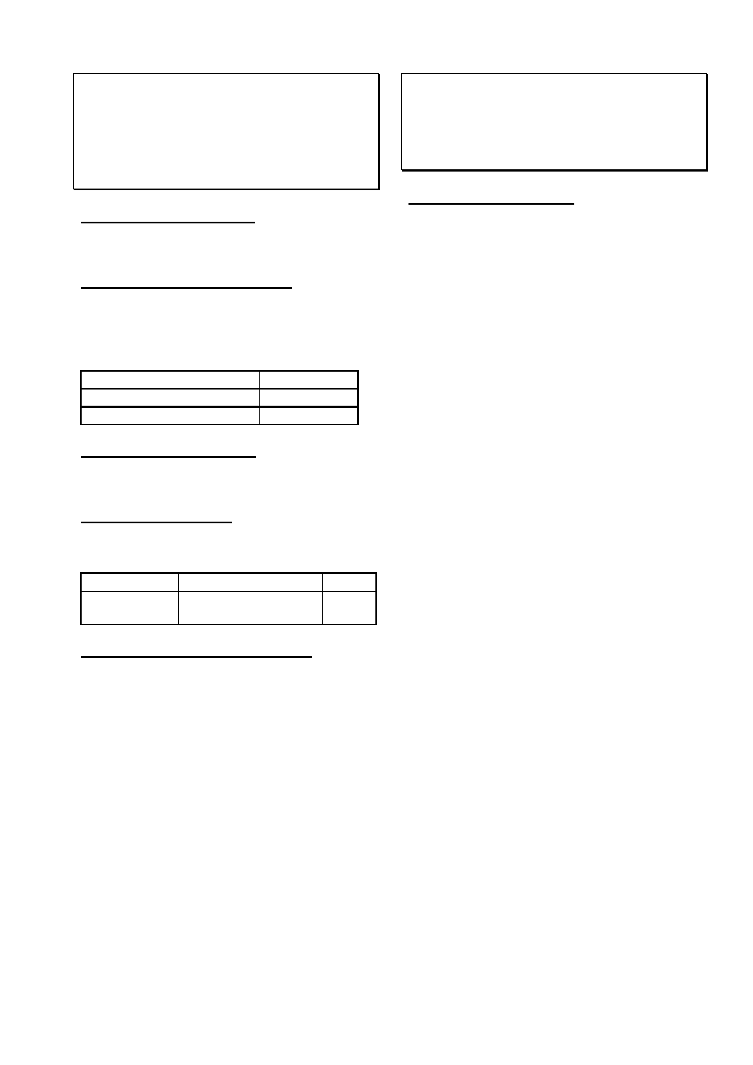
PROBLEM DESCRI PTION
When the TAG plate was fitted at Port of Entry
the PCM wiring loom, under the radiator
support panel, may have been damaged.
PRODUCTION RECTIFICATION
The TAG plate will be located on the dash
panel near the compliance plate from
February 2002 (compliance date).
SERVICE RECTIFICATION
Where a vehicle is presented with the Engine
MIL illuminated check the wiring harness at the
radiator support panel, as shown in Fig. 1.
Repair any wiring damage before proceeding
with the diagnostic procedures in SIP.
WARRANTY CLAIM I NFORMATION
Description PCM Harness Repair –
Tag Plate Damage
Labour Op. No. N000704
Time 0.5 hr
Failure Code 48
Fig 1.
HOLDEN SERVICE TECHLINE________________________________________________________MARCH, 2002
13
ABS Pump Motor Operates
Continuously
Frontera Model Year 1999 & 2000
(GROUP 5) TL242-0202
PROBLEM DESCRIPTION
The ABS pump can be heard operating even
when the ignition is in the off position.
PRODUCTION RECTIFICATION
As from the following build dates surge
protection has been added to the ABS CIM
(Coil Integrated Module) to protect the Field
Effect Transistor.
ISOVIN: Build Date:
4S2UES25FY4100001 MY 00
4S2UES30EY4100001 MY 00
SERVICE RECTIFICATION
Replace the ABS CIM. Refer to LCV SIP for
the procedure)
PARTS INFORMATION
All HSPO stock has been inspected and is
Post Break Point.
Part No.: Description: Qty:
8972147040 Module Asm (CIM)
< 03/00 (Bld Date)
1
WARRANTY CLAIM INFORMATION
Use Labour Times information in Warranty
Information section of current LCV SIP.
Engine Diagnostics
Rodeo 4JH1-TC
(GROUP 6) TL243-0202
SERVICE INFORMATION
The ‘On-Board Diagnostics (OBD) System
Check’ and ‘Engine Cranks, But Does Not Run’
flow charts provided in SIP have been updated
as from March 2002 and reflect the changes
introduced with the 4JH1-TC engine.
The two charts mentioned above are the
starting point for diagnosis on any Driveability
Complaint (OBD System Check) or No Start
Situation (Engine Cranks But Does Not Run).
Although the 4JH1-TC engine contains an
advanced fuel injection system (Bosch VP44
Diesel Injection Pump) Technicians should not
over look the basic requirement for a quality
fuel supply and a common sense approach to
engine diagnostics. For example, a restricted
fuel supply could result in reduced delivery
pressure at the injection pump, reduced
injection pressure and hence a change in
timing. This could result in the engine light
being illuminated due to a timing related DTC.
HOLDEN SERVICE TECHLINE_________________________________________________________MARCH, 2002
14
Oil Pump Gasket Leak
Rodeo C22NE (2.2lt)
(GROUP 6) TL235-0202
PROBLEM DESCRIPTION
Low oil pump fastener torque and gasket
displacement could cause an engine oil pump
gasket leak.
PRODUCTION RECTIFICATION
The production procedure to torque the oil
pump housing bolts has been revised from the
engine number below.
The revised procedure allows for a consistent
torque setting to be achieved.
Engine Number Build Date:
C22NE 25057516 30/10/01
SERVICE RECTIFICATION
Replace the oil pump gasket. For procedure
refer to LCV SIP.
IMPORTANT
• The torque specification for the oil pump
housing bolts in LCV SIP is incorrect
prior to March 2002 (6 Nm). The correct
torque specification is 8-12 Nm.
• Do not attempt to fit the metal oil pump
gasket used in other Holden 2.2lt engine
models.
PARTS INFORMATION
Part No.: Description: Qty:
92060519 Gasket – Oil Pump
(Paper Gasket)
1
92065913 Gasket – Crankcase
to Cylinder Block
1
WARRANTY CLAIM INFORMATION
Description Pump, and/or Gasket,
Engine Oil- Replace
Labour Op. No. J102100
Time 5.9 hr
Failure Code 42

HOLDEN SERVICE TECHLINE_____________________________________________________________________APRIL, 2002
12
Engine Oil Consumption Information
All
(GROUP 6A) TL260-0203
This Techline is provided for general information.
All engines require oil to lubricate and protect the
load bearing and internal moving parts from wear
including cylinder walls, pistons and piston rings.
When a piston moves down its cylinder, a thin film
of oil is left on the cylinder wall. During the power
stroke, part of this oil layer is consumed in the
combustion process. As a result, varying rates of
oil consumption are accepted as normal in all
engines.
Many external factors, such as owner driving habits
and vehicle maintenance, can affect the rate of oil
consumption.
The following are some important items affecting
oil consumption which must be taken into account
when evaluating customer complaint vehicles.
Gasket and External Leaks
Inspect the oil pan and engine covers for leakage
due to over-tightened, damaged, or out of place
gaskets. Inspect oil lines and fittings for signs of
leakage.
Improper Reading of the Oil Level Indicator
(Dipstick)
Verify that the dipstick tube is fully seated in the
block. When checking the oil level, make sure the
dipstick is wiped clean before taking an oil level
reading and fully
depress the dipstick until the shoulder bottoms out
on the dipstick tube. The dipstick should be the
proper part number for the engine/vehicle that is
being checked.
Not Wai t i ng Long Enough After Running Engine
to Check Oil Level
The vehicle should be allowed to sit for at least 10
minutes after the engine has been shut off, before
taking an oil level reading to assure the oil has had
enough time to drain back into the crankcase. In
order to ensure accurate results, the temperature
of the oil should be close to the same temperature
as the last time the oil level was checked.
Improper Oil Fill After an Oil Change
Following an oil change, verify that the proper
amount and type of oil was put in the engine and
that the oil level on the dipstick is not above the full
mark or below the add marks. Refer to the
Owner's Manual or Service Manual for information
on recommended oil quantity, viscosity, and
quality.
High Speed or High RPM Driving
Continuous driving at high speeds/high RPMs may
increase oil consumption. Because this may not
always be an everyday occurrence, it is hard to
determine exactly how much the oil economy will
be affected.
Towi ng or Heavy Usage
Towing a trailer will increase oil consumption and
may cause oil consumption to fall below the normal
accepted rate referenced in this bulletin for an
unloaded vehicle in a personal use application.
Large frontal area trailers will further increase the
work required from the engine, especially at
highway speeds, and thus increases the rate of oil
consumption.
Crankcase Ventilat ion System
Verify that the positive crankcase ventilation (PCV)
system is operating properly. Incorrect PCV
valves, blockages, restrictions, or damage to the
PCV system can result in increased oil use.
Oil Dilution (Fuel and Water)
On vehicles that are usually driven short distances,
less than 8 km, especially in colder weather,
unburned fuel and condensation generated from
cold engine operation may not get hot enough to
evaporate out of the oil. When this occurs, the
dipstick may indicate that the oil level is over-full.
Subsequent driving on a trip where the engine is at
normal operating temperature for 30 minutes or
more, will vaporize excess moisture and fuel, and
may give the customer the impression of excessive
oil consumption if the oil level is checked
immediately after.

HOLDEN SERVICE TECHLINE_____________________________________________________________________APRIL, 2002
13
Engine Temperature
If an engine is run at overheated temperatures (see
Owner's Manual or Service Manual) for more than
brief periods, oil will oxidize at a faster than normal
rate. In addition, gaskets may distort, piston rings
may stick, and excessive wear may result. Verify
that all cooling system components are in proper
working order.
Engine Wear
Piston scuffing, excessive piston-to-wall clearance,
tapered or out of round cylinders, worn, damaged
or improperly installed valve guides, seals and
piston rings will all cause an increase in oil
consumption.
HOLDEN SERVICE TECHLINE_____________________________________________________________________APRIL, 2002
16
Ignition Keys - Immobiliser
Rodeo & Jackaroo
(GROUP 12) TL263-0203
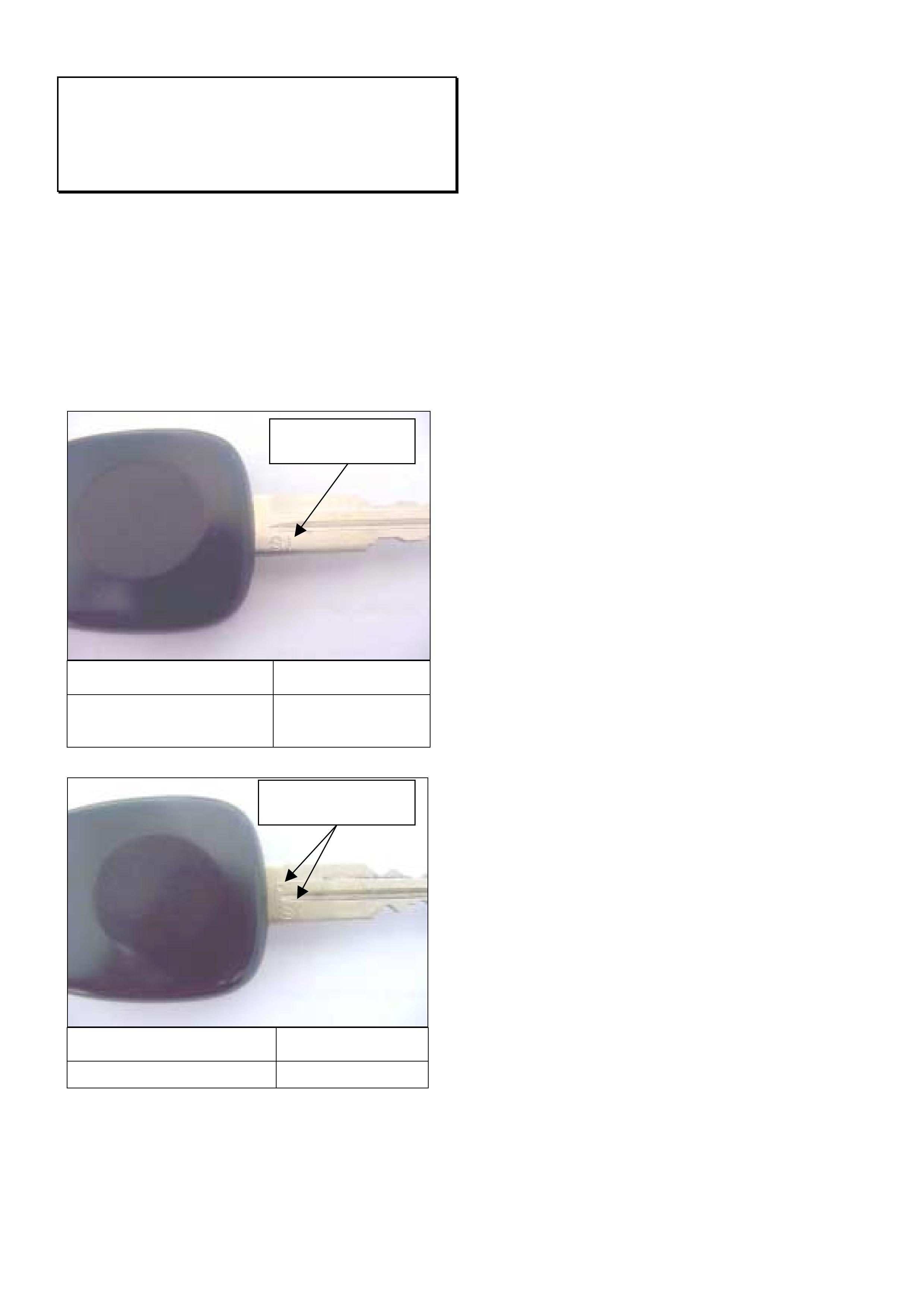
When replacing an ignition key it should be noted
that Rodeo Diesel (4JH1) has a unique key.
Although the keys are almost identical in
appearance a different brand immobiliser is used
in vehicles fitted with the 4JH1 engine.
To differentiate between the two types of keys
inspect for the identifiers as shown below.
Applicable Models Key Part Number
Jackaroo (6VE1 & 4JX1)
Rodeo (Except 4JH1) 8971706800
Applicable Model Key Part Number
Rodeo (4JH1 Only) 8973001640
Key marked with SI
and a dot.
Key marked with SI
only
HOLDEN SERVICE TECHLINE___________________________________________________________________ MAY, 2002
6
Seat Belts Not Extending
UES Frontera
(GROUP 1) TL253-0204
PROBLEM DESCRI PTION
Numerous Frontera seat belts returned through
the warranty system cannot be faulted. The
reason for replacement of these belts is given as
"seat belt will not extend" or "seat belt jamming".
Customers and Retailer staff may be unaware of
the seat belt “Child Restraint Locking Mechanism”
feature. The rear outer seat belts and front
passenger seat belt have an automatic locking
mechanism designed for securing child restraint
seats. When this locking mechanism is
activated, the seat belt is prevented from being
extended. The mechanism is activated and
deactivated as follows.
To activate the system extend the seat belt to its
full length. Once activated, the seat belt can only
be retracted and a clicking noise will be heard
from the seat belt mechanism when the ratchet
operates on retraction.
To deactivate the system allow the belt to fully
retract. This releases the locking ratchet and the
belt returns to normal operation.
SERVICE RECOM MENDATION
To avoid mis-diagnosis of seat belts, Holden
Retailer frontline staff should familiarise
themselves with the operation of the Child
Restraint Locking Mechanism. They will then be
able to explain this feature to any customers who
complain that their seat belts are “jamming”.
NOTE: The UES Frontera owner's handbook
explains operation of the Child Restraint Locking
Mechanism in the section on “seat belts”. Be
aware that owner handbooks with a print date
prior to November 2001 neglected to mention that
the front passenger seat also had this feature.
NOTE: Seat belts replaced unnecessarily for
complaint of “not extending” will not be accepted
as warranty.
Exhaust Resonance
SWB FRONTERA 2.2lt (X22SE)
(GROUP 8) TL205-0801
PROBLEM DESCRI PTION
Customers may report resonance from the
exhaust under acceleration.
SERVICE RECTIFICATION
NOTE: This fix cannot be applied to the 2.0lt
Frontera manufactured prior t o 1999 M Y.
• Fit a new exhaust muffler and tail pipe.
• Discard the bolts used at the front of the
muffler; use the nuts listed below in this
position.
PARTS INFORMATION
Parts are supplied through HSPO.
Part No.: Description: Qty:
97165240 Muffler - Exhaust 1
97165238 Tail Pipe - Exhaust 1
8971487571 Gasket – Exhaust 2
0911502100 Nut 2
WARRANTY CLAIM I NFORMATION
Description Exhaust Resonance Fix
Labour Op. No. L000208
Time 0.8 hr
Failure Code 40
Update
HOLDEN SERVICE TECHLINE___________________________________________________________________ MAY, 2002
7
Dust Entry Diagnosis – Luggage Area
Jackaroo
(GROUP 1) TL205-0101
PROBLEM DESCRI PTION
Some customers may report excessive dust entry
into the rear luggage area when a vehicle is
frequently operated in dusty conditions.
Note: Customers should be advised that driving
a vehicle with an open window or the ventilation
system in the re-circulate position can lower the
cabin pressure increasing the likelihood of dust
entering the cabin.
SERVICE RECTIFICATION
Use the following information as a guide for repair
when dust entry into the rear luggage area is
considered excessive:
Note: Complete the following steps for both
sides when the dust entry appears to be
throughout the rear of t he vehicle.
1. Remove the third row seat assembly.
2. Remove the rear end floor trim cover.
3. Remove the rear luggage side trim covers.
4. Remove the luggage area floor fittings ie. tie
down points.
5. Lift the carpet to expose the wheel arch panels
and rear floor panel sealing beads.
6. Remove the jack and jack bracket if dust
appears to be entering from behind the panel.
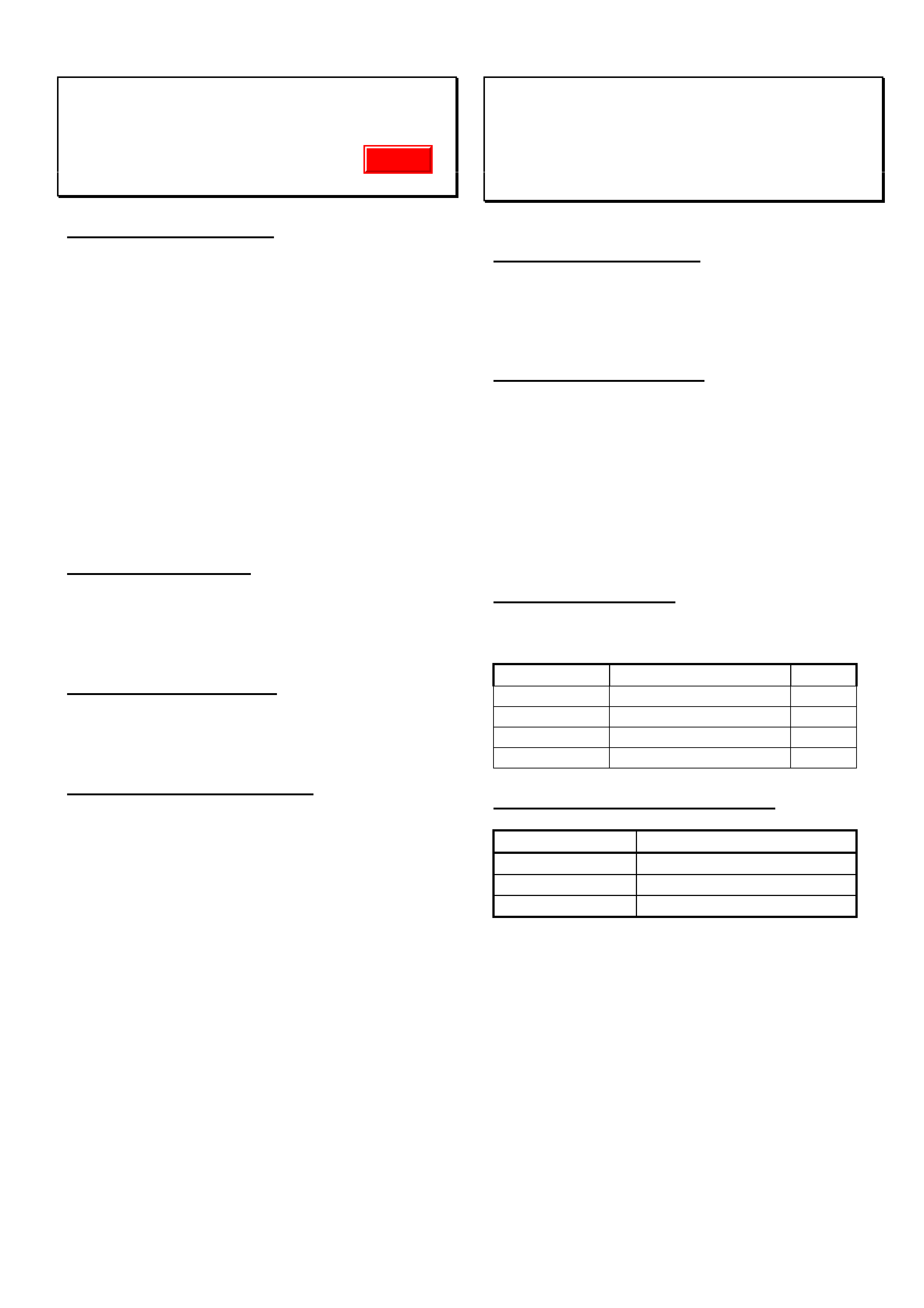
7. Remove the exterior splashguard from the
wheel arch as shown in Fig 1. The guard flare
does not need to be removed.
Fig. 1
8. Inspect for correct sealing at the panel joins
and for evidence of dust entry. Pay particular
attention to the seams indicated in Fig.2.
Fig. 2
9. Inspect for correct sealing at the panel joins
along the entire length of the wheel arch. Pay
particular attention to the seams indicated in
Fig.3.
Fig. 3
Exterior
Splash Guard
Guard
Flare

HOLDEN SERVICE TECHLINE___________________________________________________________________ MAY, 2002
8
10. Where it is difficult to detect the exact point of
dust entry do the following:
Close all doors and windows with a second
person in the vehicle. From the exterior of the
vehicle move an air blower and a lead light over
all panel seams and other areas of potential
dust entry (e.g. tail lights and door hinges)
while the second person in the vehicle
observes for areas of leakage.
11. Clean dust from any leaking areas and seal all
gaps using Silicone Sealant RTV 732 part
number 92140051.
NOTE 1: For leakage around the door hinge
area refer to Service Techline Group 1,
November 1998.
NOTE 2. Do not seal panel drain holes.
12. Reassemble the vehicle as required.
13. Submit a PIR to Holden indicating the areas
requiring sealing.
HINT: An alternative method of finding air leaks to
that described in step 10 is as follows:
Close all windows and doors. Operate the heater
fan on the highest speed with vents set to fresh air.
Feel around the potential leak areas at the rear of
the vehicle for air leaking from the vehicle.
PARTS INFORMATION
Description Part Number
Silicone Sealant RTV 732 92140051
HOLDEN SERVICE TECHLINE____________________________________________________________________ JUNE, 2002
15
Check Strap Noise (Popping)
Frontera (UES)
(GROUP 1) TL206-0205
PROBLEM DESCRI PTION
When opening a front door a loud popping or
clicking noise can be heard from the door check
strap.
PRODUCTION RECTIFICATION
A revised check strap bush has been in
production from the following breakpoint.
ISOVIN: Build Date:
4S2UES25F24100690 Feb. 2002
SERVICE RECTIFICATION
Note: The revised bushings described in this
Techline can be fitted to the rear door check strap
arms if required. However, the rear check arms
should only be repaired if reported as noisy.
Inspect The Check Strap Bush
1. Remove the check strap pin by tapping the
pin upwards using a soft hammer. Take care
not to cause paint damage with the hammer.
2. Inspect the pin for signs of wear and replace
only if necessary.
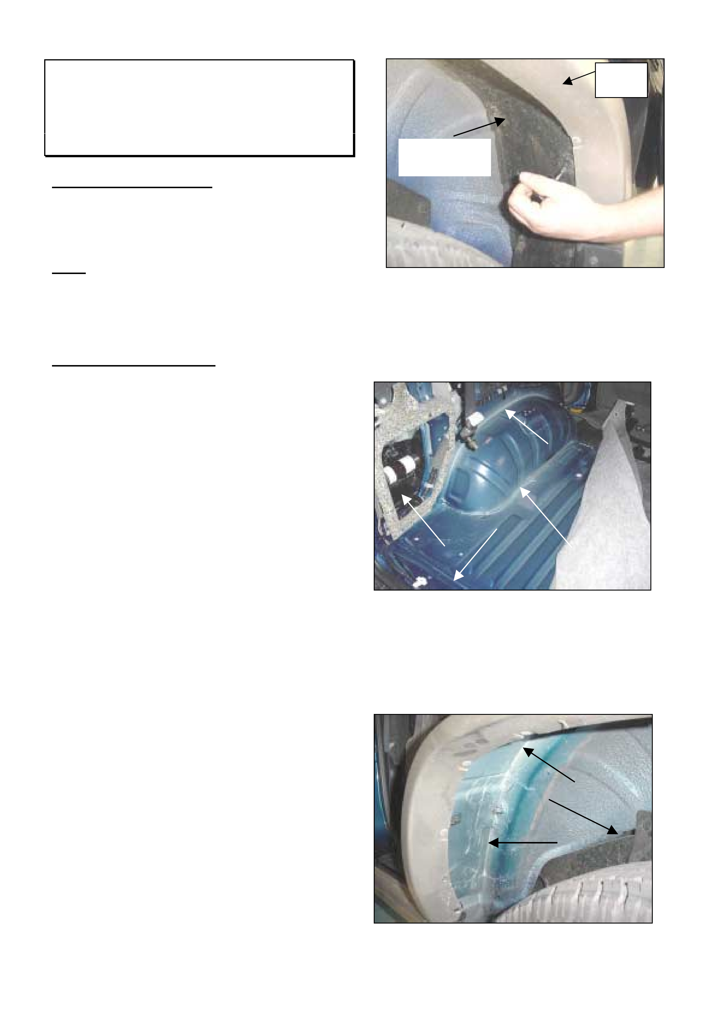
Fig 1
3. Remove the check strap arm from the body
mount and inspect the bush to confirm wear.
Fig 2.
4. If the check arm is fitted with a plastic or gold
bushing, as shown in Fig. 2, refer to the
following bush replacement procedure.
5. If the check arm has no bush, as shown in
Fig. 2, refer to the following check strap
replacement procedure.
Bush Replacement Procedure
1. Remove the plastic or gold bush from the check
arm.
2. Fit the revised black bush to the check arm in
the same direction as the removed worn bush
(refer Fig. 3). Note: It may be necessary to
use pliers to install the new bush completely. If
so, protect the new bush by wrapping in a cloth
before applying pressure to prevent scratching.
Fig. 3
3. Apply molybdenum grease to the pin hole and
both sides of the new bush. Note: Failure to
apply grease to the check arm bush could
cause premature failure of t he new bush.
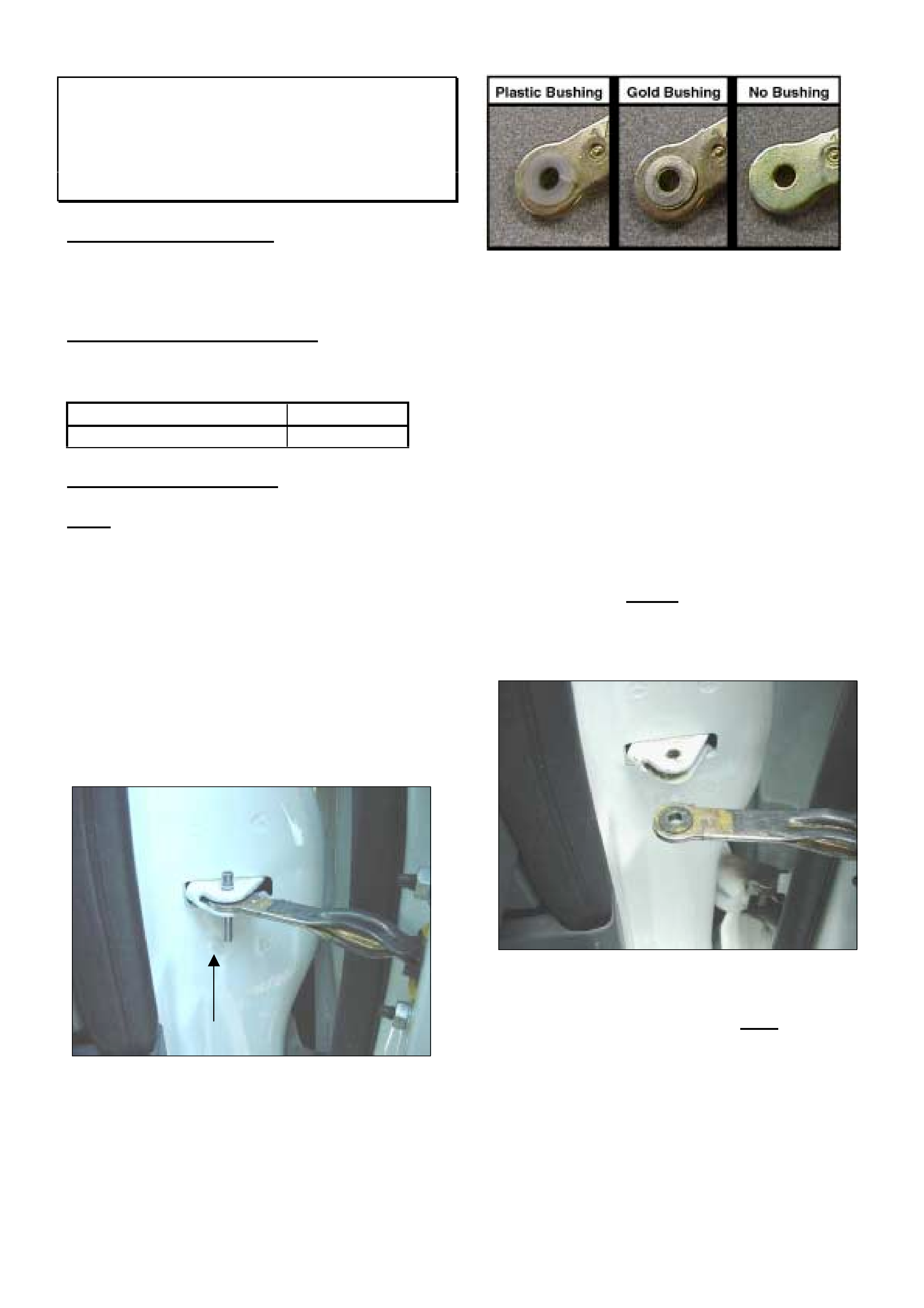
4. Fit the check arm into the body mount and align
the pin hole.
5. Fit the pin with the slot facing the door
assembly and tap into place (Refer Fig. 4).
HOLDEN SERVICE TECHLINE____________________________________________________________________ JUNE, 2002
16
Fig. 4
6. Repeat the procedure for the opposite front
door.
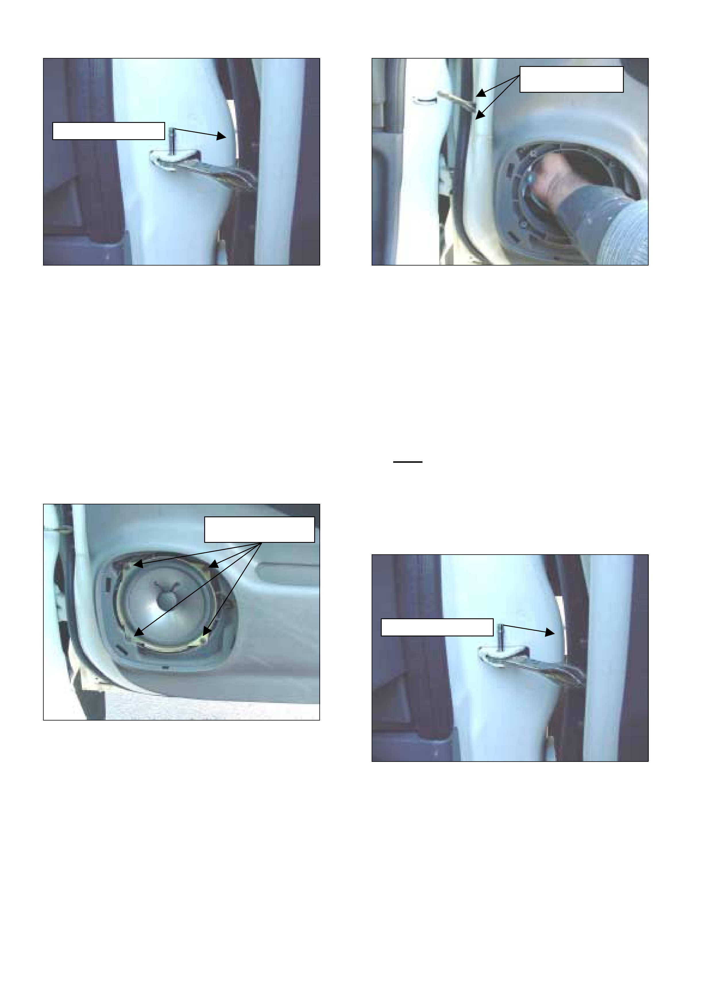
Check Strap Replacement Procedure
1. Move the window to the fully up position.
2. Remove the door speaker cover.
3. Remove the 4 speaker screws, disconnect the
speaker harness connector and remove the
speaker (Fig. 5).
Fig. 5
4. Remove the check strap assembly retaining
nuts.
5. Reach through the speaker mount into the door
cavity and remove the check strap assembly
(Fig. 6)
Fig. 6
6. Install the new check arm assembly into place
through the speaker opening.
7. Reinstall the two check arm retaining nuts and
tighten (torque: 5.1 lbs. Ft. (6.9 NM) +/- 1.4 lbs.
Ft. (1.9 NM).
8. Apply molybdenum grease to the pin hole and
both sides of the bush.
Note: Failure to apply grease to the check
arm bush could cause premature failure of
the new bush.
9. Fit the pin with the slot facing the door
assembly and tap into place (Refer fig. 4).
Fig. 7
10. Repeat the procedure for the opposite front
door.
Pin slot facin
g
door
Speaker Screws
Retaining Nuts
Pin
s
l
o
t fa
c
in
g
doo
r
HOLDEN SERVICE TECHLINE____________________________________________________________________ JUNE, 2002
17
PARTS INFORMATION
Part No.: Description: Qty:
8973247840 Check Strap Arm
Bush (Black). 2
8973253310 Check Strap Ass. 2
8941114680 Check Strap Pin If
required
WARRANTY CLAIM I NFORMATION
SIP has been updated with the following labour
codes and times.
Description Bushing, Check Arm
Front R/H - Replace
Labour Op. No. B407200
Time 0.2 hr
Failure Code 06
Description Bushing, Check Arm
Front L/H - Replace
Labour Op. No. B407300
Time 0.2 hr
Failure Code 06
Description Check Assembly, Front
R/H - Replace
Labour Op. No. B407000
Time 0.6 hr
Failure Code 06
Description Check Assembly, Front
L/H - Replace
Labour Op. No. B407100
Time 0.6 hr
Failure Code 06
HOLDEN SERVICE TECHLINE_______________________________________________________________JULY, 2002
Rear Axle Seal Leak
TF Rodeo
(GROUP 4) TL206-0401
PROBLEM DESCRI PTION
Investigations show the rear axle shaft seal could be
damaged by the axle shaft during assembly.
PRODUCTION RECTIFICATION
An auxiliary jig has been introduced in production to
align the axle shaft and seal/housing assembly from
the following break points.
ISOVIN: Build Date:
JAATFR25H27102440 March 2002
JAATFR55H27100771 March 2002
JAATFR30H27102382 March 2002
JAATFR77H27114200 March 2002
JAATFS25H27101760 March 2002
JAATFS55H27102300 March 2002
JAATFS77H27107780 March2002
MPATFS55HYT100212 Feb 2000
MPATFR25HYT100064 March 2000
MPATFR30HYT100003 March 2000
MPATFS25HYT100003 June 2000
PIR any post break point failures.
SERVICE RECTIFICATION
Replace the axle seal using the axle shaft disassembly
and reassembly procedures in LCRV SIP. Path: TF
➜
Clutch, Trans and Drive Train
➜
Rear Axle
➜
Axle
Shaft.
Note: It is extremely important to apply grease to
the axle seal and adjust the axle shaft end float as
described in the axle shaft re-assembly procedure.
PARTS INFORMATION
Part No.: Description: Qty:
5096250920 Seal - Axle As
required
WARRANTY CLAIM I NFORMATION
Use existing information in LCRV SIP.
A/C Compressor Hose – Servicing
Precaution
Jackaroo w ith Turbo Diesel Engine MY01
onw ards
(GROUP 2 & 12) TL305-0206
PROBLEM DESCRI PTION
When the suction or discharge hoses are removed
from the air conditioning compressor on above models
it is possible for PAG compressor oil to leak into the
alternator which is located directly below the
compressor. This oil has the potential to damage the
alternator and nearby wiring harnesses.
SERVICE RECOM MENDATION
It is recommended that whenever working on the
compressor refrigerant hose connections, a rag is
placed over the alternator and nearby wiring to prevent
any damage from PAG oil.
HOLDEN SERVICE TECHLINE ___________________________________________________________________ AUGUST, 2002
Front Wheel Bearing - Revised Service
Procedure
Frontera (2002 MY)
(GROUP 3) TL298-0207
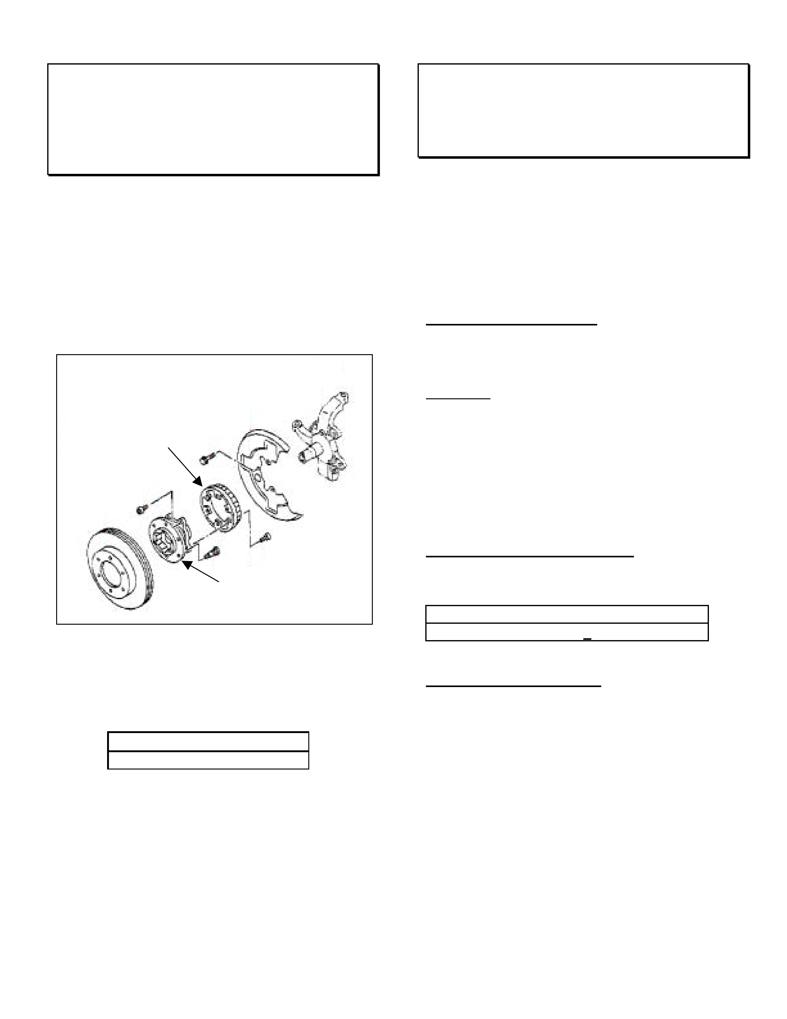
SERVICE PROCEDURE CHANGE
The 2002 Model Year Frontera has a sealed front
wheel bearing hub assembly that does not require
grease replacement.
The bearing assembly is not meant to be dismantled.
The revised service schedule requires the hub
assembly to be checked for excessive axial play at
100, 000km intervals.
How To Identify A 2002 “Model Year” Vehicle
A 2002 Model Year vehicle can be identified by the 2 in
the ISOVIN as shown below.
ISOVIN: ↓
↓↓
↓
4S2UES25F24100000
Vehicles with later hub assemblies can also be
identified by the exposed drive shaft nut, as seen on
most front wheel drive vehicles.
Fuel Gauge Inaccurate
UES Frontera up to MY02
(GROUP 8) TL299-0207
This Service Techline supersedes previously released
information in Dealer Letters DL 09/00 or IGM 09/00.
IMPORTANT: If an affected vehicle is currently not
covered by new vehicle warranty, please refer to
your District Manager – Aftersales to discuss
warranty approval.
PROBLEM DESCRI PTION
Instability of the fuel pump / gauge assembly in the fuel
tank can result in an incorrect fuel level reading (too
low).
Symptoms:
• Fuel gauge needle does not move past the full
indicator when the fuel tank is filled to capacity.
• The fuel gauge reads ½ when the vehicle has been
driven approx. 130km after filling to capacity.
• Fuel tank can only be replenished with 60 lts when
the fuel gauge needle is directly on the empty
position.
PRODUCTION RECTIFICATION
All MY 02 vehicles and later have the revised fuel
pump / sender assembly fitted.
ISOVIN:
4S2UES25F2100001
SERVICE RECTIFICATION
Check the gauge and circuit for normal operation as
per following procedure.
1. Remove the connector from the fuel pump/sender
assembly without removing the fuel tank as shown in
fig 1.
Bearing Hub Ass.
ABS Sensor Ring
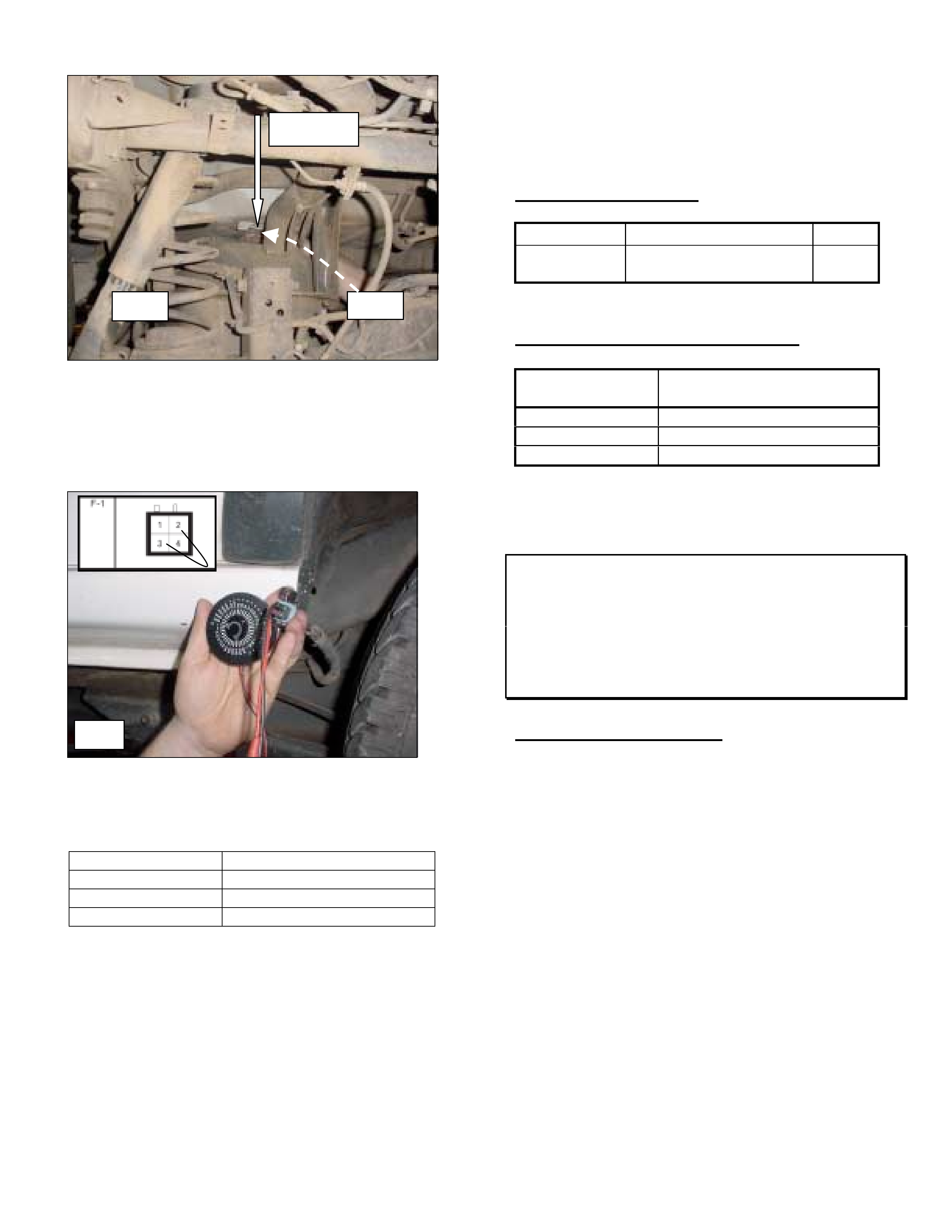
HOLDEN SERVICE TECHLINE ___________________________________________________________________ AUGUST, 2002
2. Install a variable resistor between pins 2 and 3 at the
loom connector (F1) as shown in figure 2. Ensure
the correct resistance scale is selected ie not K
ohms and not M ohms.
3. Check that the gauge performance matches the
figures in the table below. The gauge is slow
moving and could take minutes to stabilise.
Resistance OHMS Gauge Reading +/- 2mm
103 E
45 ½
24 F
4. After confirming the gauge performance is within
specification replace the fuel pump sender assembly
following the procedure described in LCRV SIP.
Location in LCRV SIP
1999 – 2000 Section 6C Fuel Tank
2001 Section 8A Fuel Tank
PARTS INFORMATION
Part No.: Description: Qty:
8253415990 Fuel Pump / Sender
Ass.
1
WARRANTY CL AIM INFORMATION
Description Gauge Unit Ass. – Fuel
Tank
Labour Op. No. N000393
Time 0.9 hr
Failure Code 57
Injector Harness Connector Locking Tabs
Break – Servicing Caution
UBS Jackaroo Diesel (4JX1)
(GROUP 6Y) TL322-0207
PROBLEM DESCRI PTION
When removing the locking tabs on the injector
harness connector, do not over stress the lock tab
otherwise breakage may result. The locking tab should
only be lifted as far as is required to release the
connector.
Holden is in the process of establishing supply of the
injector harness connectors separately. Current
indications are that only the connectors at the injector
will be established as separate parts. Should the oil
rail pressure or temperature sensor connector fail the
complete harness will need to be replaced.
Retailers will be advised via a Service Techline when
the individual connectors are available.
Acces
Connect
Fi
g
Fi
g
HOLDEN SERVICE TECHLINE________________________________________________________________OCTOBER, 2002
13
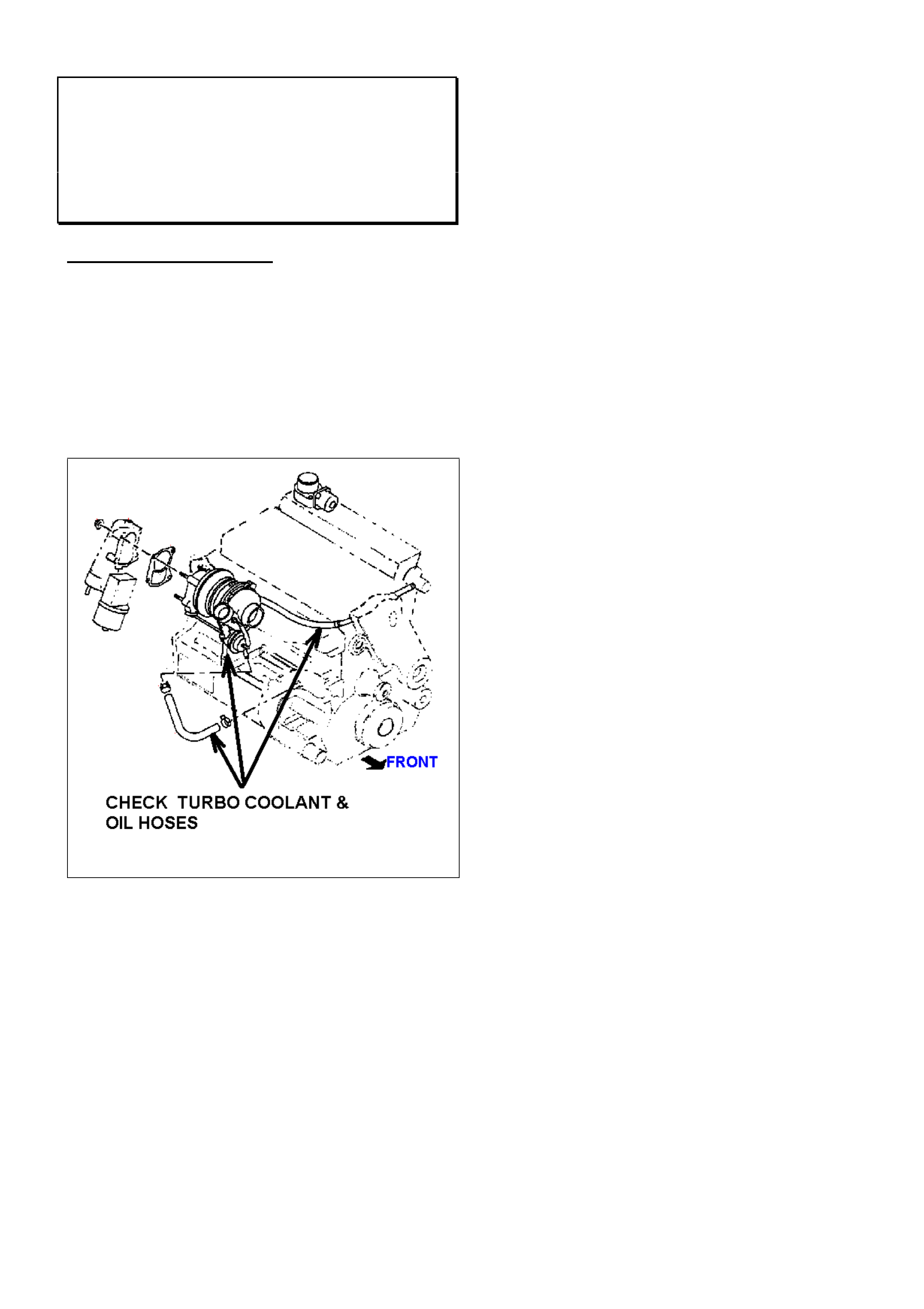
Turbo Coolant and Oil Hose Inspection
Hint
UBS Jackaroo 4JX1 TC
(GROUP 6K) TL347-0209
SERVICE REQUIREMENT
The two coolant hoses and the oil return hose
connected to the turbo charger should be inspected for
deterioration at every service, as outlined in the
maintenance schedule.
As these hoses are subjected to extreme operating
temperatures, and are not located in an immediately
obvious position, particular attention is required to
thoroughly inspect the hoses.

HOLDEN SERVICE TECHLINE_______________________________________________________________SEPTEMBER, 2002
7
ABS Modulator Damage When Replacing
Brake Pads
All Carlines with ABS
(GROUP 5) HINT TL331-0208
PROBLEM DESCRIPTION
Some complaints have been received from retailers
describing ABS Modulators internal seal damage
during replacement of brake pads.
SERVICE RECTIFICATION
When pushing brake pistons back into the caliper,
extreme care must be taken!
Caliper piston diameter is relatively large compared to
master cylinder piston diameter. This means the
caliper piston, when forced back into the caliper, is
pumping a large quantity of brake fluid back through
the system at high velocity and pressure.
In some cases, fluid under these conditions can
cause damage to ABS modulator seals.
It is essential that caliper piston retraction be done
slowly and carefully. It is preferable to use a pad
spreading tool. If using a G-clamp, an example of a
suitable slow speed would be one-quarter turn of the
handle per second.
Service Literature (SIP and TIS2000) for pad
replacement also states fluid reservoir level will
increase when pushing back caliper pistons. It is
important not to allow fluid to overflow and spill onto
paintwork.
It has been suggested that loosening the bleed nipple
on the caliper is one method of avoiding both ABS
Modulator damage and fluid overflow.
Holden does not endorse this practice for the
following reasons:
1. Customers will be charged unnecessarily for fluid
replacement if the reservoir needs to be topped
up
2. Attempting to loosen the bleed nipple unnecessarily
exposes Service Departments to associated
costs if, for example, the nipple is broken due to
corrosion.
Remember – paint, caliper or ABS modulator damage
as a result of piston retraction is not a warrantable
defect and repair costs are carried by your Service
Department!
Clutch Pedal Freeplay Checks
(Change to Maintenance Schedule)
YG Cruze with M/T
(GROUP 7A) TL341-0208
The Owners Handbook Maintenance Schedule
currently states to check the clutch pedal freeplay
initially at 30,000km and then every 15,000km
thereafter.
At the next reprinting of the Owners Handbook the
maintenance schedule will be changed to show the
initial check to be done at 15,000km and then every
15,000km thereafter.
Retailers are requested to immediately commence
clutch pedal freeplay checks at the 15,000km service
and at every 15,000km thereafter.
The procedure for checking clutch pedal freeplay is
found in LCV SIP as follows.
Select – Automatic & Manual Transmissions,
Clutch
Select – Section 7C Clutch
Select – 3 On Vehicle Service
Select – 3.2 Clutch pedal and bracket
Select – Clutch pedal free travel
HOLDEN SERVICE TECHLINE_______________________________________________________________SEPTEMBER, 2002
8
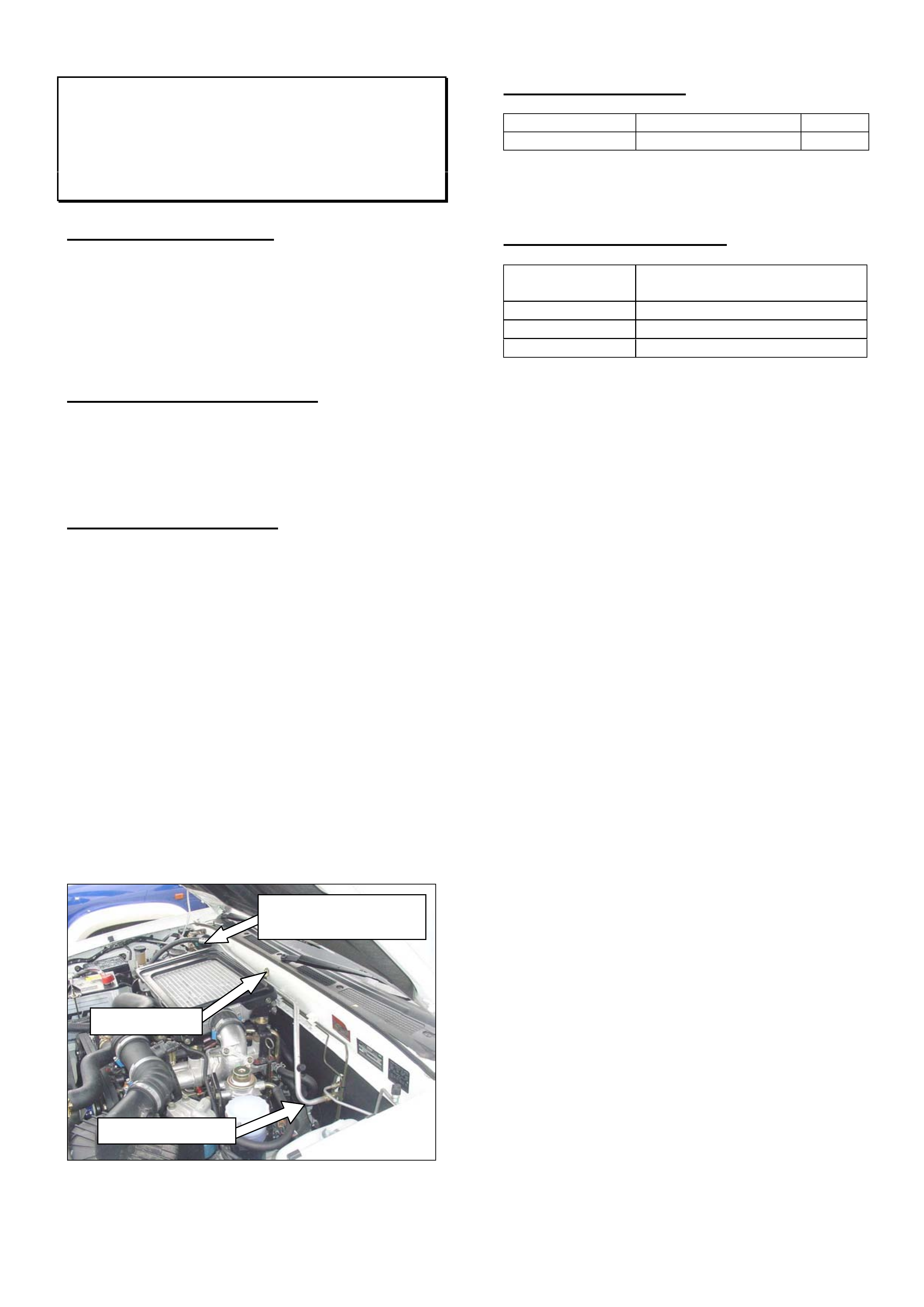
A/C Pipe Knock
Rodeo 4JH1 TC
(GROUP 2) TL330-0208
PROBLEM DESCRIPTION
A knocking noise heard from the engine bay area
under load could be incorrectly diagnosed as a
mechanical engine knock.
Movement in the air-conditioning suction pipe
mounting bracket at the centre of the dash panel in
the engine bay could be the cause of the noise.
PRODUCTION RECTIFICATION
The revised screw (PN 92146330) will be supplied in
future kits.
Break Point Summary will updated when information
is available.
SERVICE RECTIFICATION
To confirm if the air conditioning pipe bracket is the
cause of the noise, isolate the bracket from the dash
panel by removing the existing mounting screw and
confirm if the noise is eliminated.
Proceed once the bracket mounting is confirmed as
the source of the noise.
1/ Replace the A/C pipe bracket screw at the dash
panel with PN 92146330.
2/ Check that the suction pipe (large diameter) at the
evaporator is at 90o to the dash panel. The pipe may
have been bent during tightening at installation.
If required, gently bend the suction pipe at the
evaporator until it is at 90o to the dash panel. Check
that there is at least 20mm clearance between the
suction pipe and brake hose at the master cylinder.
Figure 1
PARTS INFORMATION
Part Number Description Qty
921463300 Screw- Dash Panel 1
Stock is expected mid Sept 2002; part number
11072643 can be used in the interim.
WARRANTY INFORMATION
Description A/C Pipe Bracket – Replace
Screw
Labour Op. No. D000336
Time 0.3 hr
Failure Code 40 Noisy
Check for bent tube
Replace Screw
Check there is 20mm
clearance to brake pipe.
HOLDEN SERVICE TECHLINE_______________________________________________________________NOVEMBER, 2002
7
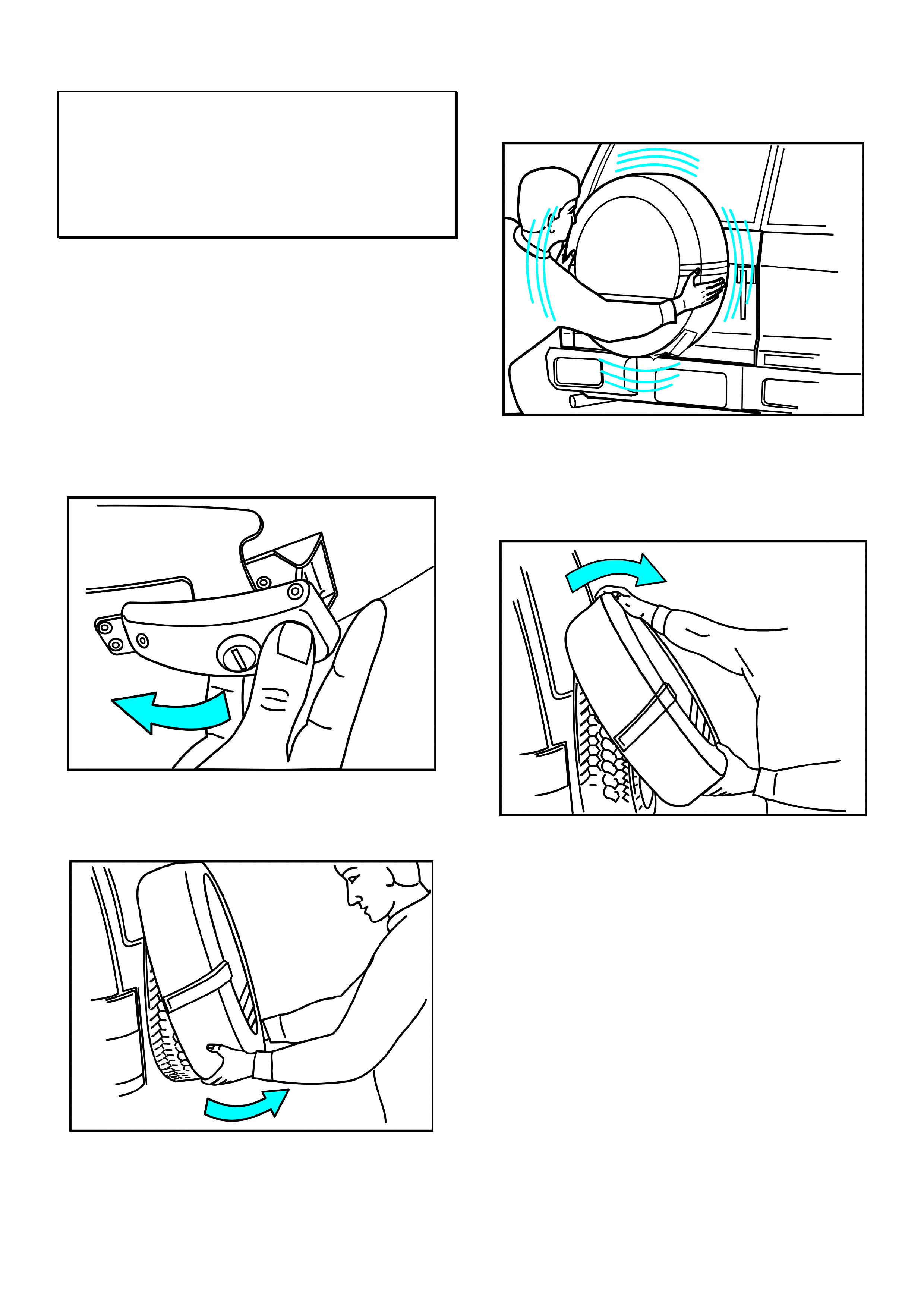
Spare Wheel Hard Cover Removal
Procedure
UBS JACKAROO
(GROUP 10) TL371-0210
The spare wheel hard cover on some Jackaroo models
has proven difficult for some customers to remove and
replace.
To assist customers, instructions and illustrations as
shown below, will be included in the Owner’s Handbook
when it is next reprinted.
Removal Procedure.
1. Unlock the latch with its dedicated key then loosen
by lifting up and to left as shown in Figure 1..
Figure 1.
2. Grasp the cover as shown in Figure 2. and tilt
upwards, towards you.
Figure 2.
The cover is designed to be a tight fit and therefore
must be “wriggled” and “eased” over the tyre. Figure 3.
Figure 3.
3. The bottom edge of the cover must be clear of the
tyre before it can be lifted up and off as shown in
Figure 4.
Figure 4.
Replacement is the reverse of removal.
It may be necessary to relocate the tab on the locking
latch before tightening the latch
HOLDEN SERVICE TECHLINE_______________________________________________________________NOVEMBER, 2002
8
Roof Rail Trim Cover Dislodges
YG Cruz e
(GROUP 1) TL360-0210
PROBLEM DESCRI PTION
The trim covering the front roof rail mounting fasteners
may dislodge.
PRODUCTION RECTIFICATION
Revised trims with larger retaining tabs have been
fitted to vehicles at Port Of Entry from the beginning of
Sep 2002. As a guide, all reworked vehicles will have a
Compliance plate dated from Sep 2002 onwards.
SERVICE RECTIFICATION
On complaint vehicles install revised trim covers as
shown in Parts Information.
PARTS INFORMATION
Part No.: Description: Qty:
92128866 Cover RHF 1
92128867 Cover LHF 1
All parts in HSPO stock are the revised type.
WARRANTY CLAIM I NFORMATION
Use Labour Times information in Warranty Information
section of current PV SIP CD
Injector Sleeve Replacement
UBS JACKAROO with 4JX1 DIESEL
ENGINE
(Group 6M) TL323-0210
PROBLEM DESCRI PTION
Until recently, the injector sleeve seals in the Jackaroo
4JX1 engine have not been serviceable. They are now
serviceable with the use of a special tool which was
forwarded to every Holden Retailer attached to Retailer
Letter RL72/02.
PRODUCTION RECTIFICATION
Injector sleeves with revised o-ring material were
introduced in production from:
VIN Date
JACUBS73GY7102028 03/11/1999
SERVICE PROCEDURE
Use following procedure to replace injector sleeves.
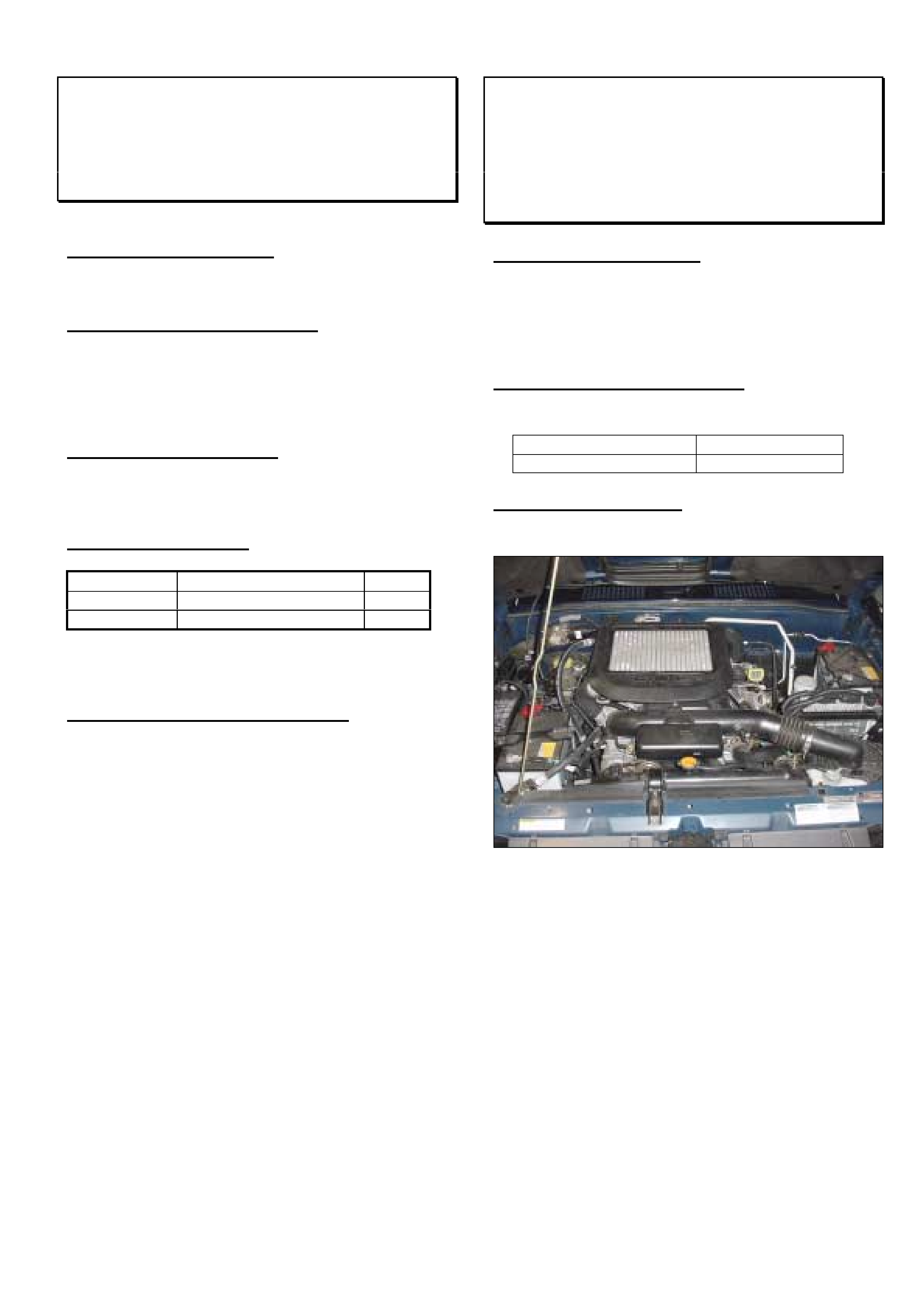
Figure 1. – Working Environment
In preparation for this repair:
§ Check position C2 on the Vehicle Service History
Label to see if the procedure has been previously
completed.
§ Disconnect the battery negative (-) cable/s.
§ Loosen the radiator drain plug and drain
approximately 5 litres of coolant from the radiator
1. Follow LCV-SIP instructions and remove the
injectors and oil rail assembly. Remove oil rail and
injectors as one assembly while avoiding oil entry
into the combustion chamber.
NOTE: Ensure the injectors are installed in the same
positions on the oil rail from which they were removed.
Otherwise, recalibration of the ECU with Tech 2 will be
necessary.
HOLDEN SERVICE TECHLINE_______________________________________________________________NOVEMBER, 2002
9
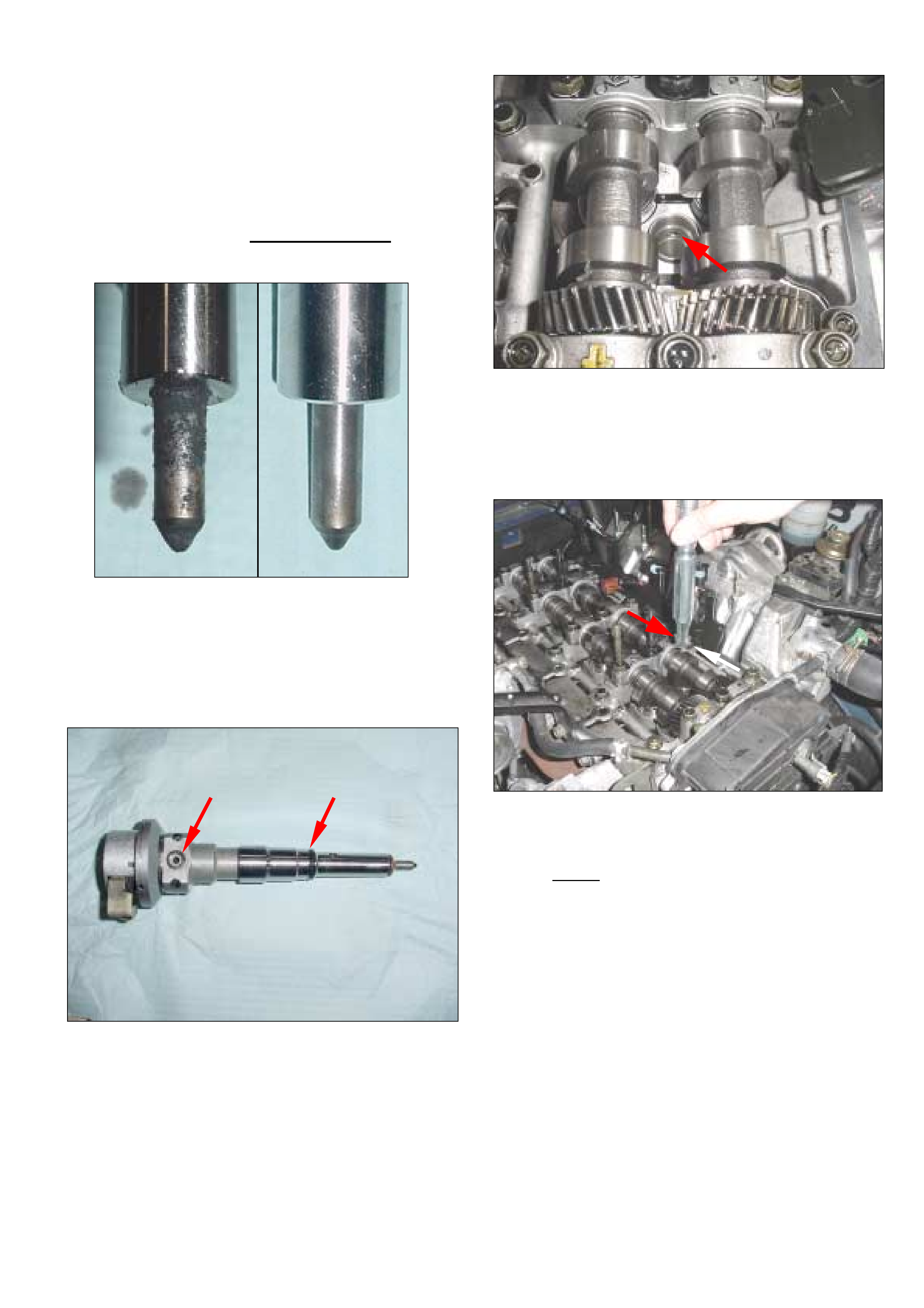
2. Clean and inspect the injectors. Wipe away soot
and deposits from the tip of the nozzle with solvent
and a rag.
3. Discard the injector Back Up O Ring and Sleeve
rework if fitted.
CAUTION: THE USE OF A BRUSH WITH
METAL BRISTLES MAY DAMAGE THE
INJECTOR NOZZLE
Before After
Figure 2 – Inspect and Clean Injectors
4. Remove and replace all injector O-rings. Lubricate
with L2 grease. Refer Figure 3.
Figure 3 – Replace Injector Seals
5. Inspect the injector sleeves in the cylinder head to
locate the fuel gallery holes. Refer Figure 4.
Figure 4 – Injector Sleeve Fuel Gallery Holes
6. Orient the sleeve removal tool so the prongs will
engage the fuel gallery holes when pushed into the
sleeve. Refer Figure 5.
Figure 5 – Orienting Sleeve Removal Tool
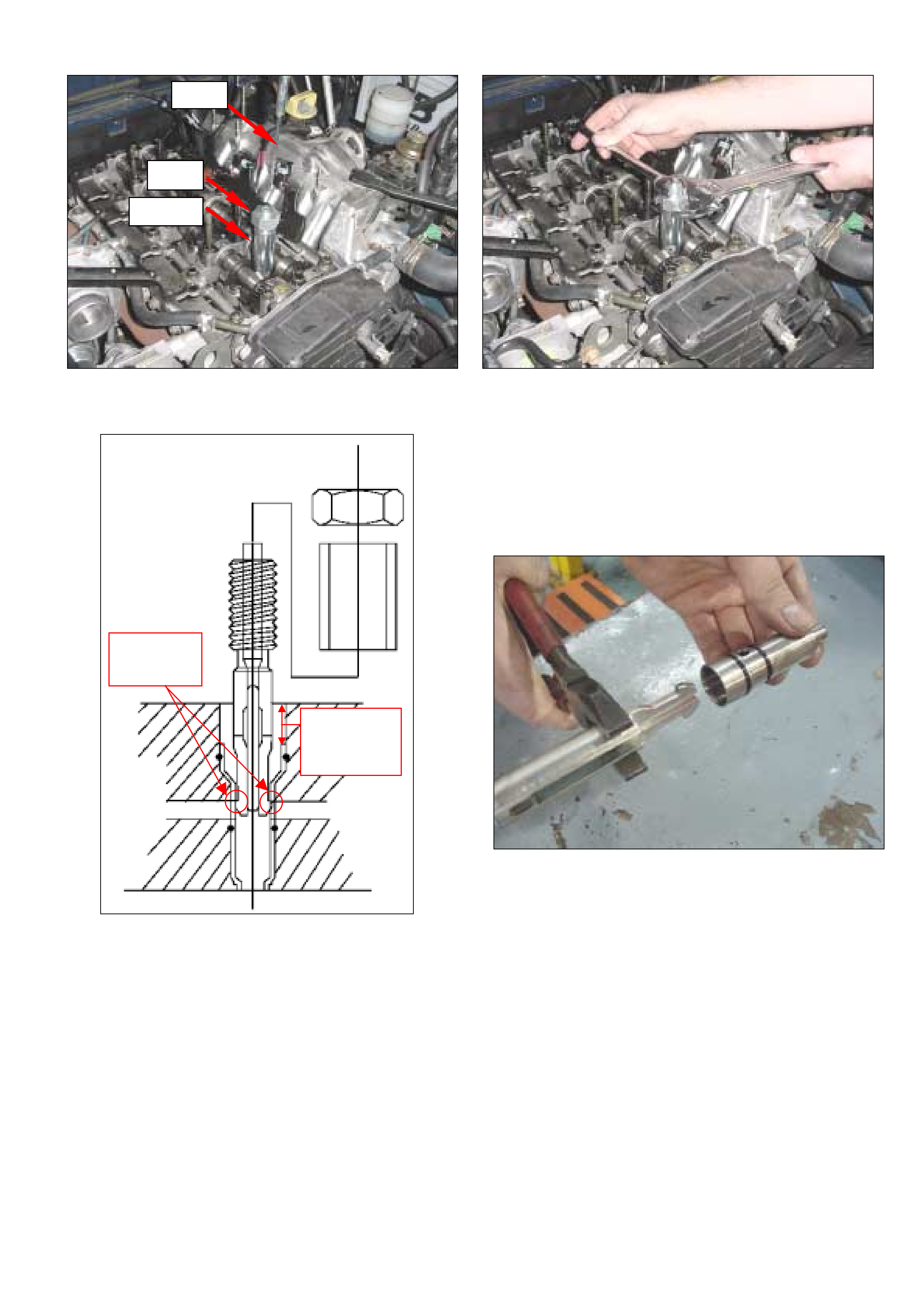
7. Push the sleeve removal tool into the sleeve until
the prongs on the tool engage the fuel gallery
holes. Twist the tool to check it is fully engaged.
Fig 7.
8. Install the tool outer sleeve and finger tighten the
nut.
9. Install the pin into the centre of the sleeve removal
tool. This keeps the tool prongs engaged in the
fuel gallery holes. If the pin does not seat fully or
becomes stuck, the sleeve removal tool is not
correctly engaged with the injector sleeve. Refer
Figures 6 and 7.
HOLDEN SERVICE TECHLINE_______________________________________________________________NOVEMBER, 2002
10
Figure 6 – Sleeve Removal Tool Assembled
Figure 7 – Tool Assembly in Cylinder Head
10. Hold the flat on the threaded section of the tool with
a wrench and turn the nut clockwise to pull the
sleeve from the head. Refer Figure 8.
Figure 8 – Extracting the sleeve using the tool
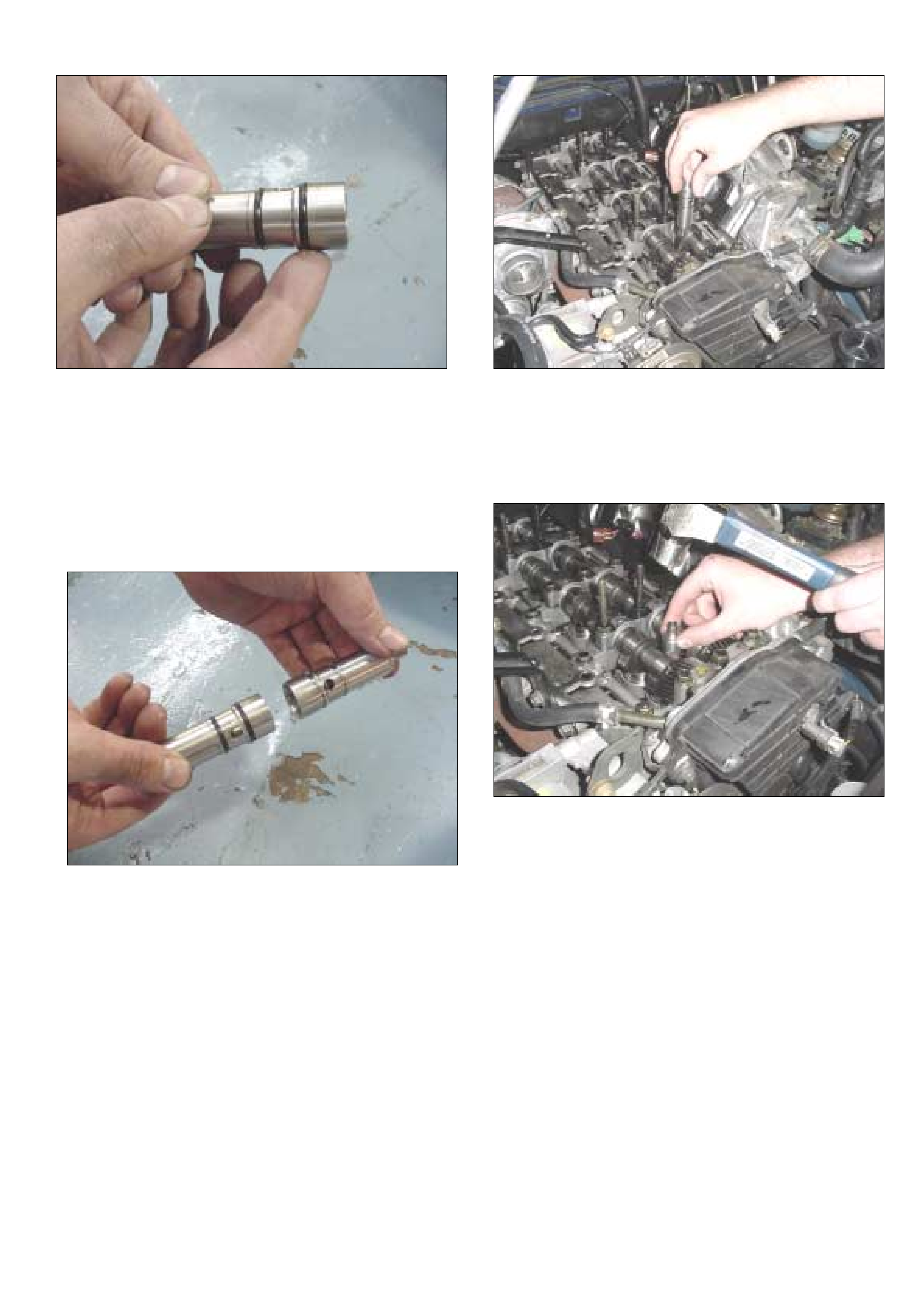
11. Remove the pin from the tool and use large pliers
to compress the body of the tool to release the
prongs from the injector sleeve. Refer Figure 9.
NOTE: DO NOT COMPRESS THE PRONGS AS
DAMAGE TO THE TOOL MAY RESULT!
Figure 9 – Removing the tool from the injector sleeve
12. Repeat this process for the remaining three injector
sleeves in the cylinder head.
13. Clean the injector sleeve bores with a lint-free rag
wrapped around a soft material such as wood.
14. Prepare the new injector sleeves for installation
by applying L2 grease to the O-rings. Refer
Figure 10.
Pin
Nut
Sleeve
Prongs
Engaged
15mm –
refer step
19
HOLDEN SERVICE TECHLINE_______________________________________________________________NOVEMBER, 2002
11
Figure 10 – Greasing new injector sleeve O-rings
15. Thoroughly clean one of the old injector sleeves to
use as an installer. Remove the O-rings in order to
identify it.
16. The old sleeve will be used upside down to install
the new sleeve. Refer Figure 11.
Figure 11 – Using old sleeve as installing tool
17. Sit the new injector sleeve in the cylinder head.
Align the fuel gallery holes in the sleeve with the
ports in the cylinder head (no photo).
18. Locate the clean, used injector sleeve upside down
on the new sleeve. Refer Figure 12.
Figure 12– Locating injector sleeves
19. Carefully install the new injector sleeve, using a
hammer, until it is fully seated in the cylinder head.
Refer Figure 13.
Figure 13 – Installing new injector sleeve
NOTE: Check the injector sleeve is fully seated in
the cylinder head by measuring the depth of the
sleeve in th e head . T he correct depth o f the sleev e
in the cylinder head is 15mm ( refer Figure 7) . Once
the sleeve is in the home position do not continue
to install the sleeve as damage may occur.
20. Repeat this procedure for the remaining three
injector sleeves.
21. Remove any oil or coolant that pooled in the
combustion chamber with a vacuum bleeder or
syringe.

HOLDEN SERVICE TECHLINE_______________________________________________________________NOVEMBER, 2002
12
22. Insert the copper packing into the injector sleeves.
Use the extraction tool pin to guide the packing into
the sleeve. Refer Figures 14 and 15.
NOTE: Th e surfaces of the copper packing create a
seal and must be clean (no visible sign of carbon
etc).
Figure 14 – Using Extractor Tool pin to guide
copper packing
Figure 15 – Installing the copper packing
23. Inspect the copper packing in the sleeve to ensure
it is installed correctly. Refer Figure 16.
Correct Incorrect (upside down)
Figure 16 – Copper Gasket Inspection
24. Install the oil rail and injectors.
Note: Carefully install the injectors into the
sleeves.
25. Install the injector H-clamp and nut and tighten
temporarily.
26. Tighten injector to oil rail bolts to the specified
torque.
Torque: 6.5 Nm (0.7 kgm / 5.1 ft lb)
27. Tighten injector H-clamp nuts to the specified
torque to seat the injectors:
Torque: 30 Nm (3.1 kgm / 22 ft lb)
28. Loosen the injector H-clamp nuts and retighten to
the specified torque:
Torque: 25 Nm (2.4 kgm / 17.4 ft lb)
29. Torque the oil rail bolts to the specified torque:
Torque: 20 Nm (2.0 kgm / 14.5 ft lb)
30. Reinstall the remaining components in the reverse
order. Refer to LCV SIP for information if required.
Note: Check that the injector electrical connection
packing seals are fitted and there is no oil in the
connection.
31. Mark position C2 on the Vehicle Service History
Label.
PARTS INFORMATION
Part No.: Description: Qty:
8971757830 Gasket – Injector
Nozzle Clamp
4
8972407980 Gasket – Nozzle
Holder
4
8971611092 Gasket – Injector
Nozzle Clamp
4
8971842160 O-Ring 2
8971606721 Gasket – Cover to
Cylinder Head
1
8972451850 Sleeve – Injector 4
WARRANTY INFORM ATION
Description Injector Sleeve – Replace
Labour Op. J000719
Time 2.2hr
Failure Code 95
HOLDEN SERVICE TECHLINE_______________________________________________________________NOVEMBER, 2002
13
Steering Rack Graunch Noise
YG Cruz e
(GROUP 9) TL359-0210
PROBLEM DESCRI PTION
A graunch noise from steering rack which usually
occurs when commencing a turn from a standing start.
PRODUCTION RECTIFICATION
Steering racks with revised bushes have been fitted to
vehicles from:
ISOVIN: Build Date:
JSAGHY81S00102263 06/08/02
SERVICE RECTIFICATION
On complaint vehicles, fit a new steering rack assembly
from HSPO, as shown in Parts Information below.
Refer to LCRV SIP for replacement procedure.
PARTS INFORMATION
Part No.: Description: Qty:
92125508 Rack asm. steering 1
WARRANTY CLAIM I NFORMATION
Use Labour Times information in Warranty Information
section of current PV SIP CD
Rear Spring Deflection (Add Additional
Leaf)
TF Rodeo – Except 4X4 V6 (All Models)
and 4X4 Diesel Cab Chassis
(GROUP 4) TL306-0210
This Service Techline supersedes the December 1997
article titled Rear Spring Sag.
PROBLEM DESCRIPTION
Some customers may complain of excessive rear
spring deflection when the vehicle is heavily laden.
SERVICE RECTIFICATION
One additional leaf can be fitted to each rear spring in
the second leaf position (second from the top) on
complaint vehicles.
Zone approval must be obtained before this
modification is carried out.
Note: Additional spring leaves are only
recommended for vehicles that are permanently
loaded such as builder’s or plumber’s vehicles or
vehicles fitted with specialised steel body work.
Additional leaves must not be fitted to 4X4 V6 (all
body models) or 4X4 Diesel Cab Chassis as heavy
duty springs are fitted in production.
When an additional leaf spring is fitted to vehicles that
operate permanently at 80% of GVM or above, an extra
25mm of camber should be applied to each spring to
assist in maintaining ride height.
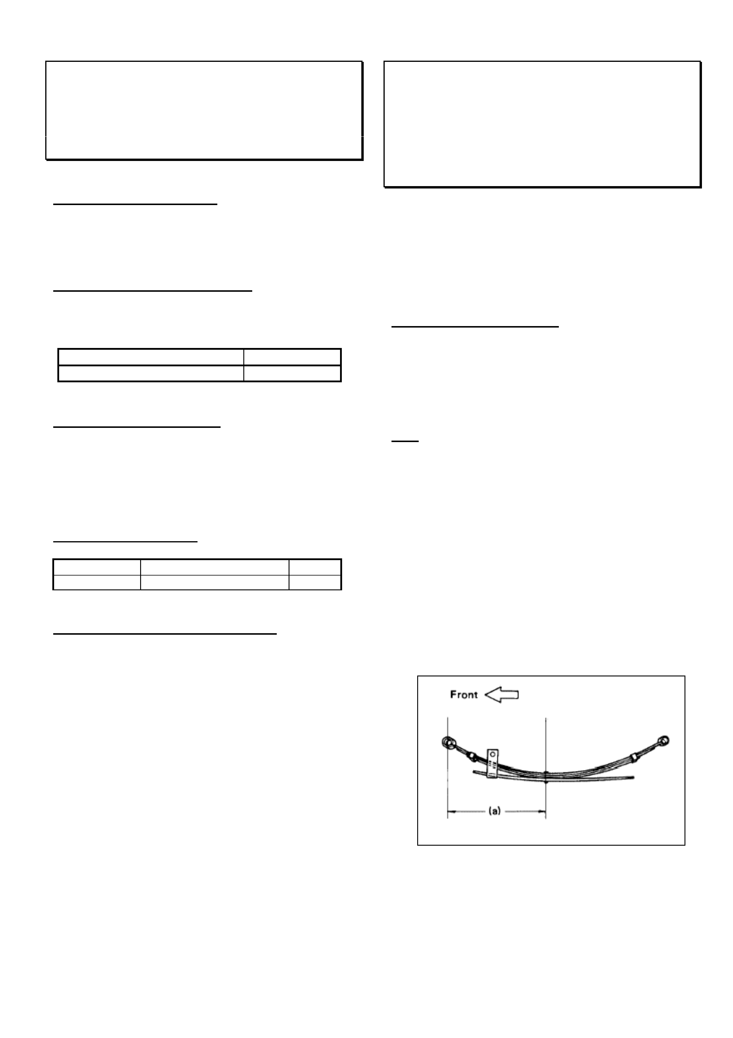
The spring assembly should be refitted with the
shortest distance (a) towards the front of the vehicle as
shown in Fig 1.
Fig 1.
Adjust the load sensing proportioning valve (LSPV)
after the modified springs have been refitted (SIP –
Section 5 – LSPV – Page 17 of 67).
HOLDEN SERVICE TECHLINE_______________________________________________________________NOVEMBER, 2002
14
PARTS INFORMATION
Parts for this spring revision are not supplied through
HSPO.
Automotive suspension spring suppliers can perform
the recommended spring modifications.
Additional leaf specification:
1150mm (High Ride Height) Length
1130mm (Low Ride Height)
Thickness 7mm
Width 60mm
Edges Rounded
Steel Type XK 9258 S
WARRANTY CLAIM I NFORMATION
Description Add Leaf to Rear Springs
Labour Op. No. F000182
Time
(Includes LSPV
adjustment)
2.2 hours
Failure Code 62
NOTE: The cost of adding leaves and re-camber of the
spring assembly can be claimed as a sublet repair.
Aftermarket Window Tinting Precautions
All
(GROUP 1) TL379-0210
PROBLEM DESCRI PTION
Some of the problems which can be caused by the
installation of aftermarket window tinting films are
detailed below:
Heated Rear Windows.
Some aftermarket window tint installers may scratch
the heating element or etch the glass (crack initiation
point) during installation of film tint material to the
tailgate glass. Because of the scratches made during
installation, the scratched heating element suffers a
semi-disconnected condition and the resistance
increases on the operating demister lines.
Also, aftermarket tint installers may disconnect the
heating terminals while affixing film tint material to the
tailgate glass and reinstall the heating terminals
loosely.
The above actions can lead to a localised overheat
condition and may result in glass breakage.
Telematics.
Aftermarket window tinting may affect the operation of
the antenna on vehicles fitted with Telematics. A
warning to this effect is given in Holden PV SIP in the
section on Telematics.
Remote Key Operation – TS Astr a
There have been isolated reports of remote key
operation being adversely affected by window tinting. A
warning to this effect is given in the TS owners
handbook.
IMPORTANT WARRANTY NOTE
Tailgate glass breakage or any other condition
which can be attributed to the installation of
aftermarket film tint material is not covered under
the new vehicle warranty.
HOLDEN SERVICE TECHLINE_______________________________________________________________DECEMBER, 2002
7
Transmission Noise In Fifth Gear
Jackaroo with AR-5 M/T Model Year 1998
and later
(GROUP 7A) TL300-0211
PROBLEM DESCRI PTION
Some customers may complain of a whining noise
when Transmission is in 5th gear.
SERVICE RECTIFICATION
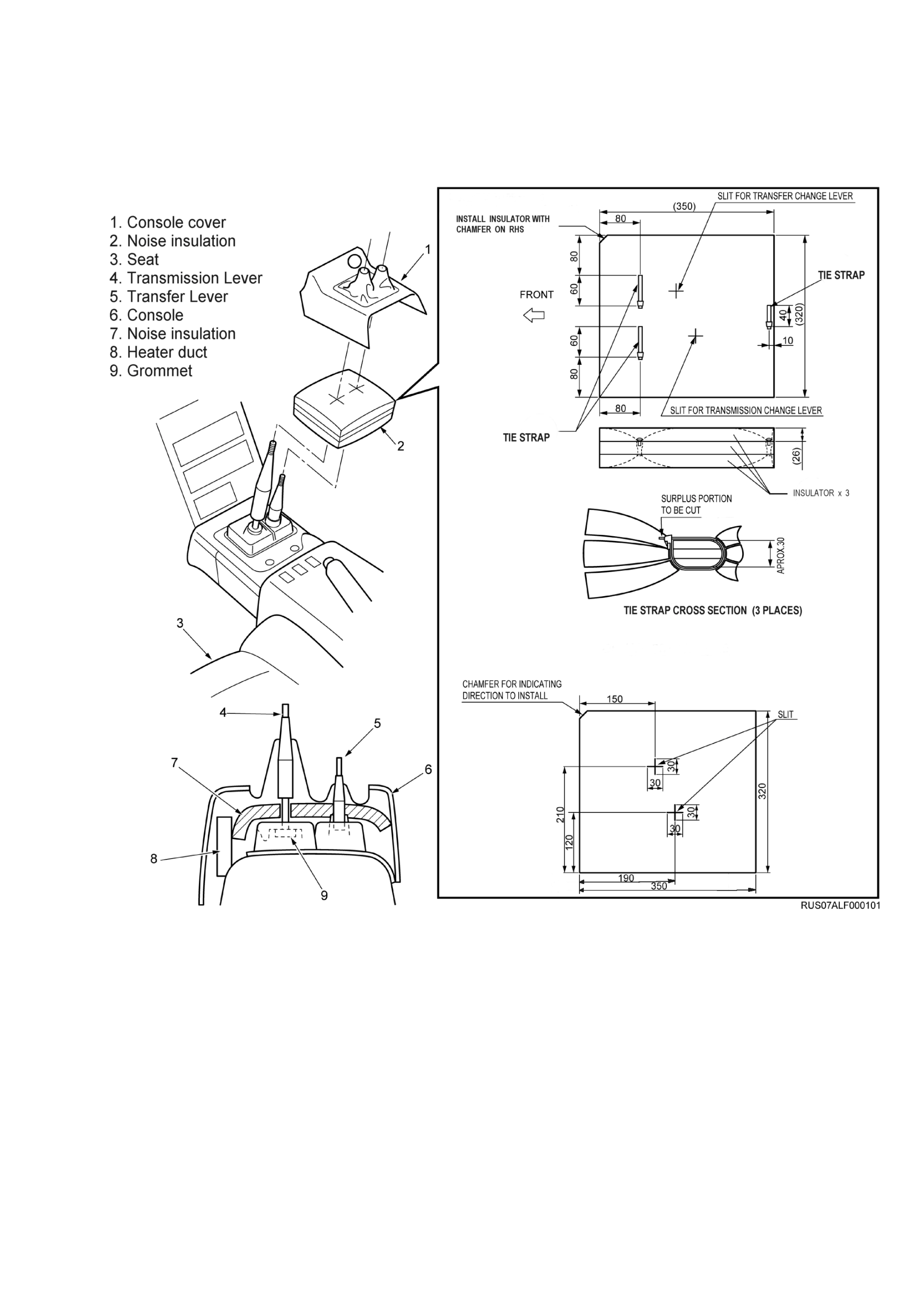
Summary: On complaint vehicles install noise
insulation between transmission and console cover.
Procedure. Refer Figure 1.
1. Bundle 3 layers of noise insulation together and
secure with 3 tie straps as shown in Figure 1. Part
numbers for these parts are shown below
.
2. Remove the centre console cover.
3. Place the insulation into position over the shift
levers as shown. The chamfered corner of the
insulation must face to the front of the vehicle.
4. Tuck the edge of the insulation into the gap
between the rear heater duct (#8) and the grommet
cover (#9).
5. Reinstall the centre console cover.
PARTS INFORMATION
Part No.: Description: Qty:
8973560730 Insulator-shift lever 3
5097070301 Clip Cable 3
WARRANTY CLAIM I NFORMATION
Description Insulator floor mounted -install
Labour Op. No. K000285
Time 0.7 hr
Failure Code 40
HOLDEN SERVICE TECHLINE_______________________________________________________________DECEMBER, 2002
8
Figure 1.

HOLDEN SERVICE TECHLINE_______________________________________________________________DECEMBER, 2002
9
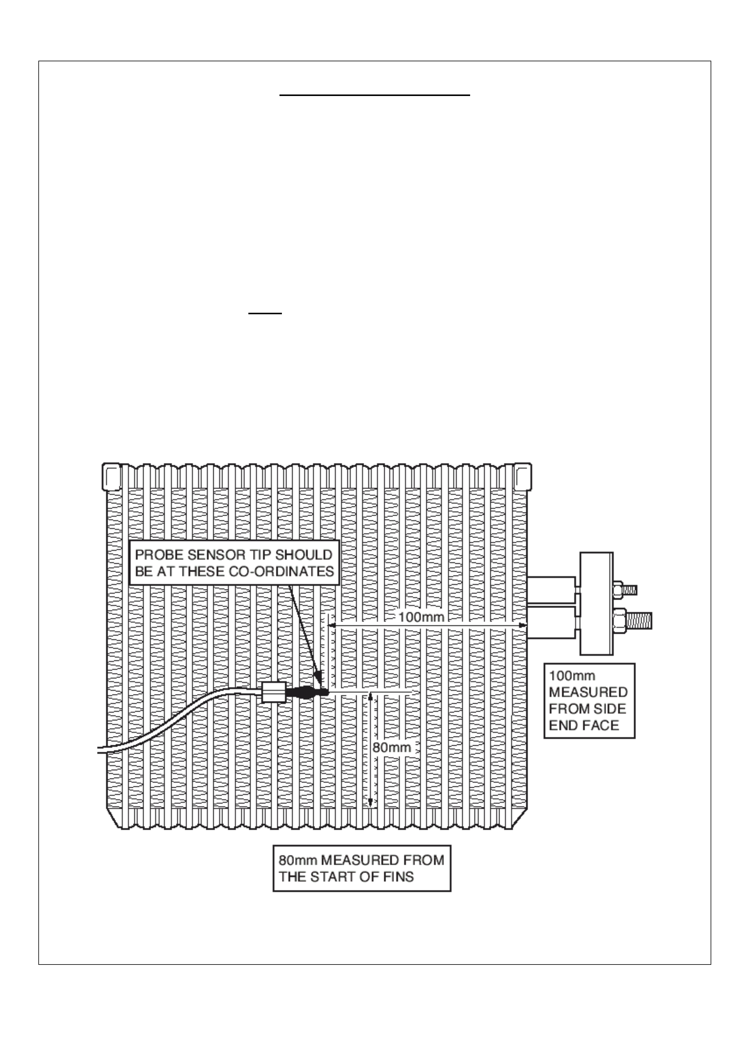
Evaporator Ice-Up - Incorrectly Positioned
Thermistor Probe
TF Rodeo with A/C from 1996-2002
(GROUP 2) TL390-0211
The following information was provided by Air
International, supplier of A/C kits for TF Rodeo.
PROBLEM DESCRI PTION
Some customers may complain that after driving for
approximately 30 minutes the A/C goes hot and the
airflow coming from the vents reduces dramatically.
Another symptom is large quantities of water draining
from the evaporator when the vehicle is stationary.
This condition results from “icing up” of the evaporator.
One of the causes of icing up can be a Thermistor
probe which is incorrectly positioned on the evaporator
coil. Because of the temperature variation across the
evaporator, it is vital that the Thermistor probe is
located exactly as specified. If it isn’t located correctly,
this can cause the compressor to continue operating
until the evaporator surface temperature drops below
zero degrees C, causing condensate to freeze on the
coil. The further build up of ice will restrict the flow of
air through the coil.
SERVICE RECTIFICATION
Summary: On vehicles with above condition, or
whenever replacing the evaporator coil, ensure the
Thermistor pr obe is loc ated as specified in the following
pages.
----------------------------------------------------------------------
1. To check the Thermistor probe location, the
Evaporator assembly will first have to be removed from
the vehicle. This will involve recovering the Refrigerant
and Re-gassing the A/C system on completion.
2. To confirm that the Thermistor probe is correctly
located on the evaporator, refer to the following 4
pages which show the Thermistor probe coordinates
for the 4 different evaporators fitted to Rodeo Petrol
and Diesel vehicles built between 1996 and 2002.
Technicians should read the comments above each
diagram to determine which evaporator is fitted to the
vehicle. The part numbers of the A/C kits can be found
on the “A/C Part Number label” fitted inside the glove
box when the A/C kit was first installed.
HOLDEN SERVICE TECHLINE_______________________________________________________________DECEMBER, 2002
10
Evaporator Identification
G A/C Kits 2.6L – M41497, M40731
V6 – M41682, 92143097
Diesel – M41682, 92141532, 92143097
2.2L – 92141750, 92142079
G Introduction – 1996 – 1999.
G Manufacturer – “Showa” Japan.
G Coil Thickness – 75 mm. Note: Measure the thickness of the Coil as there are Tw o (2)
different thickness “Showa” Coils used in the Rodeo.
G Coil Colour – Silver.
G TXV – 90 Degree w ith Equalisation Tube.
HOLDEN SERVICE TECHLINE_______________________________________________________________DECEMBER, 2002
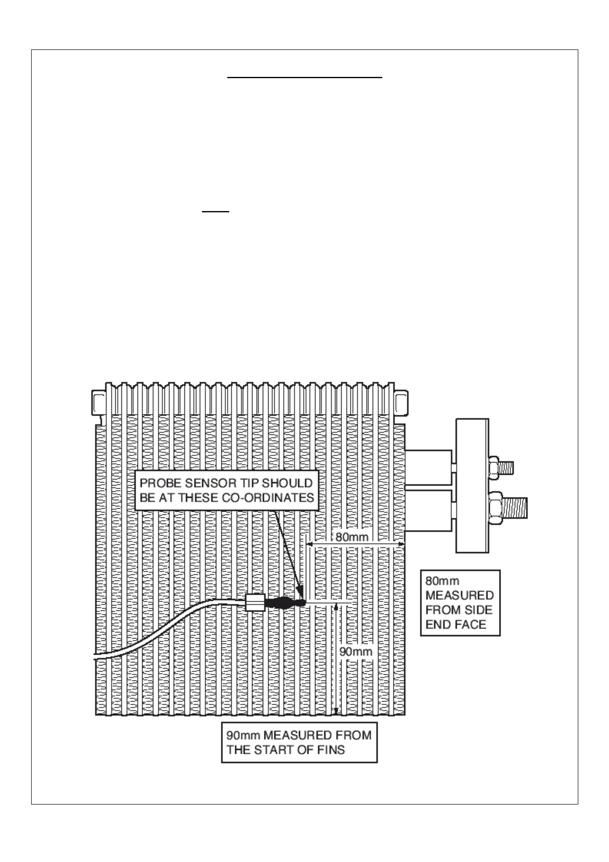
11
Evaporator Identification
G A/C Kits – V6 – 92143920. 2.2L – 92143922. Diesel – 92143921.
G Introduction – 1999 – 2001.
G
G Manufacturer – “Showa” Japan.
G Coil Thickness – 68 mm. Note: Measure the thickness of the Coil as there are Tw o (2)
different thickness “Showa” Coils used in the Rodeo.
G Coil Colour – Silver.
G TXV – 90 Degree w ith Equalisation Tube.
HOLDEN SERVICE TECHLINE_______________________________________________________________DECEMBER, 2002
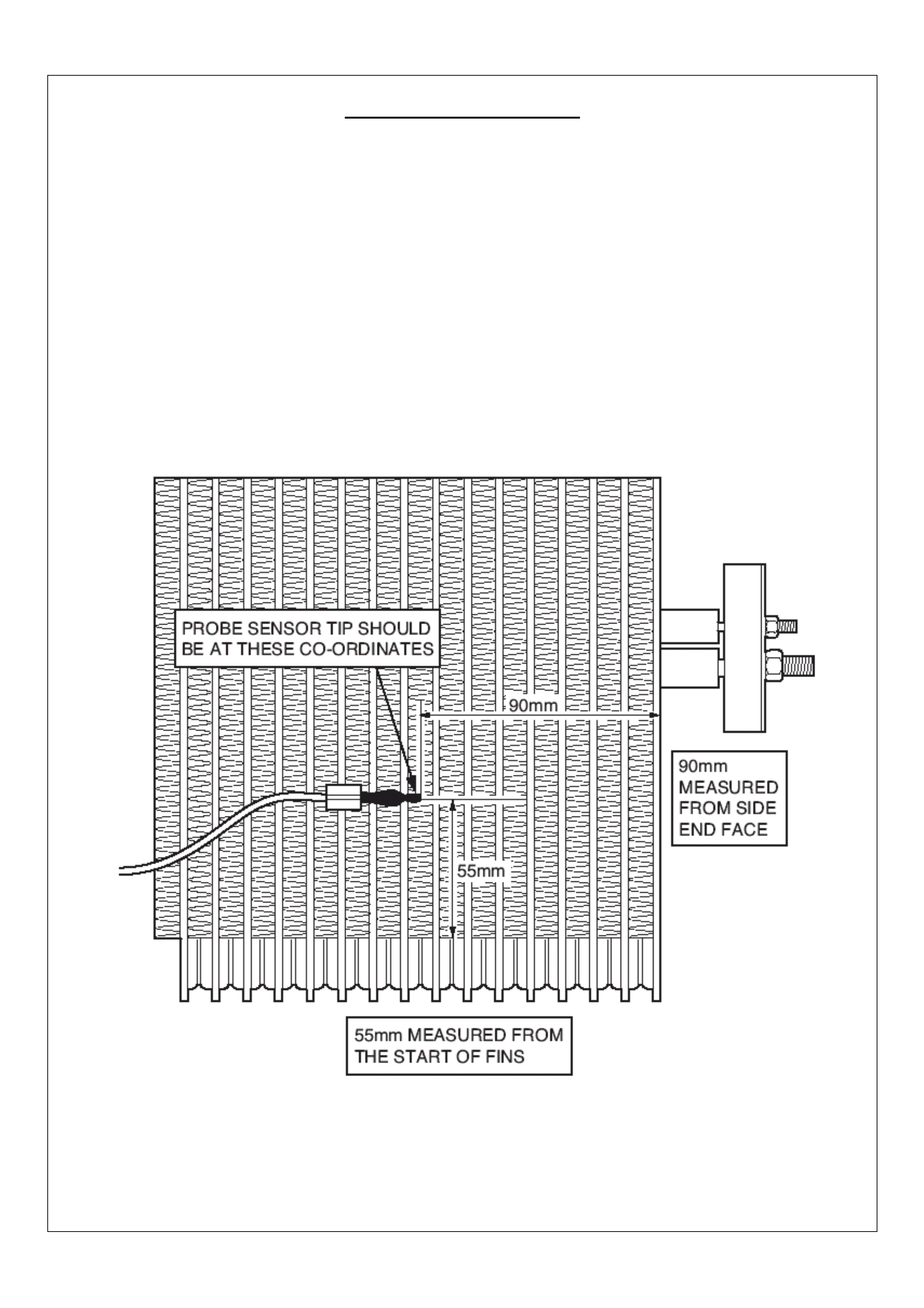
12
Evaporator Identification
G A/C Kit - V6 – 92144363. Petrol 2.2 (used kit 92143922) Diesel – 92144690.
G Introduction – 2001 to July 2002
G Manufacturer – Tripac - Australia.
G Coil Colour – Gold.
G TXV – 90 Degree with Equalisation Tube or Block Valve .
HOLDEN SERVICE TECHLINE_______________________________________________________________DECEMBER, 2002
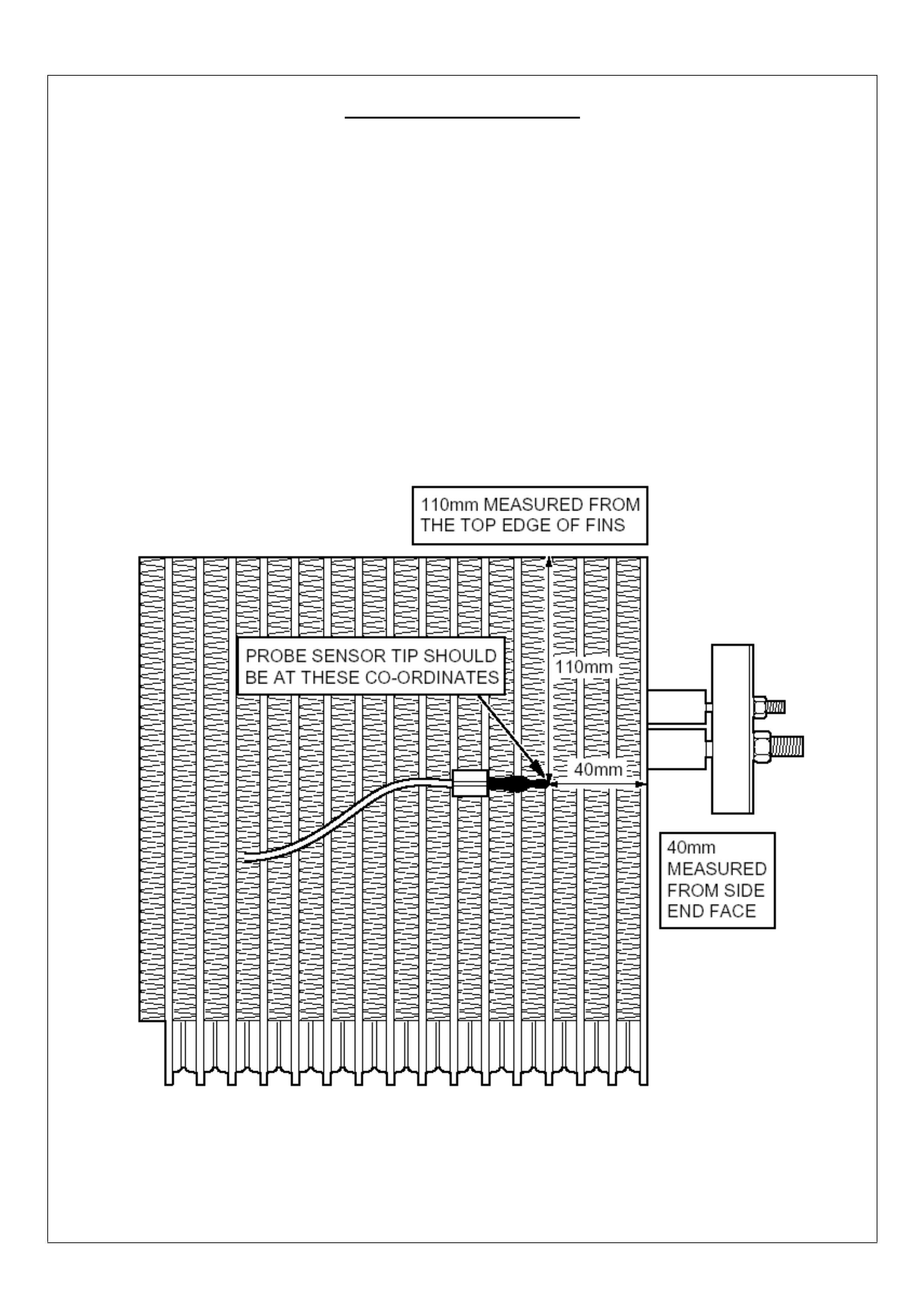
13
Evaporator Identification
G A/C Kit - V6 - 92145595. 2.2L - 92145594. Diesel - 92145593
G Introduction – July 2002
G Manufacturer – Tripac - Australia.
G Coil Colour – Gold.
G TXV – 90 Degree w ith Equalisation Tube.
G Vehicle fitted w ith Rubber Bonnet Seal.
HOLDEN SERVICE TECHLINE_______________________________________________________________DECEMBER, 2002
14
Poor A/C Performance & Evaporator
Noise
TF Rodeo (Late 2001 AND 2002)
(GROUP 2) TL301-0211
PROBLEM DESCRI PTION
Higher than expected air temperature from the A/C
vents when the A/C system is operating. Customers
may report that the A/C is not as cold as in their
previous Rodeo.
Evaporator hiss or whistle may also be reported.
AFFECTED VEHICLES
Vehicles fitted with the following parts from 2001 –
05/2002 could be affected:
Description Part Number
92144363
A/C Kit 92144690
with
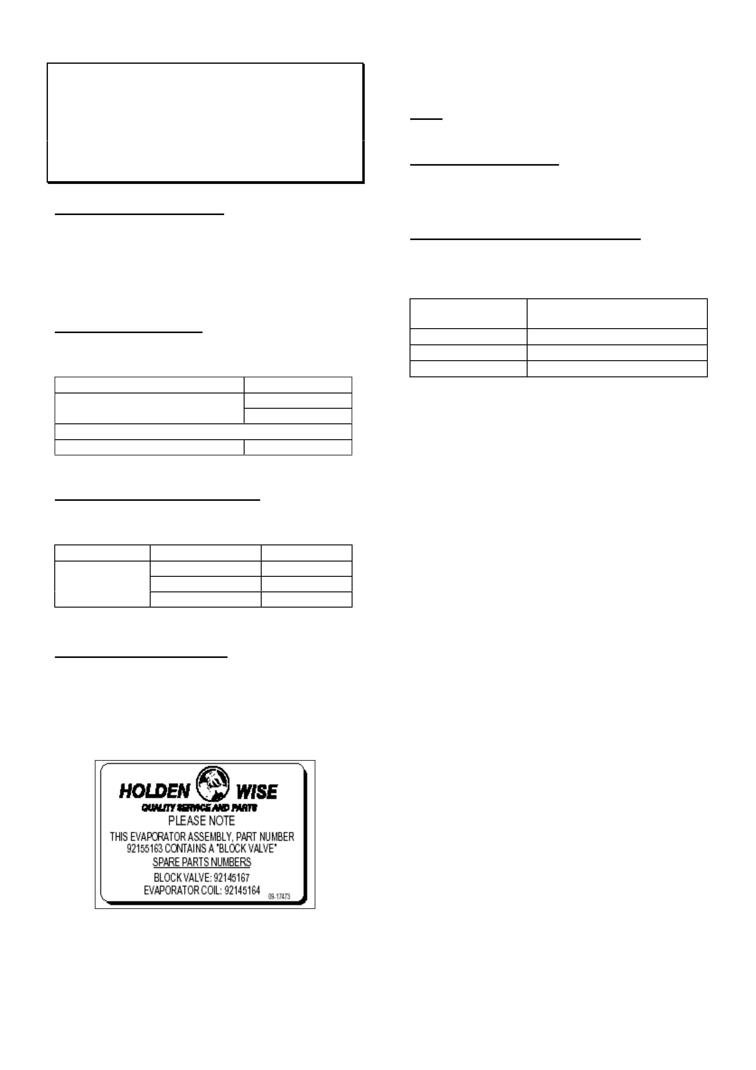
Evap. Asm. (with Block Valve). 92145163
PRODUCTION RECTIFICATION
A bonnet seal to prevent air recirculation and revised
TX valve have been added to the A/C kits from:
Date Kit Number Engine
92145595 6VD1
92145594 C22NE
05/02
92145593 Diesel
SERVICE RECTIFICATION
To establish if the vehicle could be affected:
§ Remove the glove box and inspect the
evaporator case for the white identification label
shown in figure 1.
§ If the label is not fitted or indicates a different
valve part number the vehicle is not affected.
Figure 1
§ For affected vehicles, complete the check sheet
on the follow page and fax to Air International on
(03) 9681 9734.
§ Contact Air International Service on 1800 673716
to review the results
Note: If the vehicle shows similar symptoms and is
not fitted with an affected kit contact Holden TAS.
PARTS INFORMATION
Bonnet seal and evaporators (fitted with the revised
TX valve) and will be dispatched directly from Air
International for approved vehicles.
WARRANTY CLAIM I NFORMATION
*This warranty claim is labour only as parts are
supplied directly through Air International.
Description Poor A/C Performance and
Hiss
Labour Op. No. D000339
Time 1.0 hr
Failure Code 56

HOLDEN SERVICE TECHLINE_______________________________________________________________DECEMBER, 2002
15
FACSIMILE FORM FOR RODEO A/C PERFORMANCE AND NOISE ISSUE
DATE ……/………/………..
DEALERSHIP ………………………………………………………………………………….……
DEALER CODE…………….………….. CONTACT NAME ………………………….………..
PHONE # …………………………….…. FAX # ………………………………………….……..
VEHICLE TYPE ……………………….… ENGINE……………..BUILD DATE ….…/…../……
VIN # ……………………………………………………………………………………………….…
A/C KIT PART NUMBER FITTED TO VEHICLE ……………………………………………..…
PERFORMANCE
Vehicle Set Up For Test Readings
G Maximum Cold A/C
G Blower Speed 2
G Face / Fresh Mode – Thermometer Probe Placed in the Cent re Vent
G Doors / Windows Closed
G Engine At Idl e, then held at 2, 000 RPM
G Test Duration – 5 Minut es
G Check and adjust (if requi red) the HVAC Temperature Air M i xi ng Door
G Am bient Temperature …………………..C
G High Side Pressure Reading I dl e ……………. .…2000RPM………….…….kPa / PSI
G Low Side Pressure Reading Idl e ……………. . … 2000 RPM………………. kPa / PSI
G Centre Vent Temperature Idle ……………C 2000 RPM ……………C
NOISE ONLY– How would you best describe the noise ………………………………………………..…..
………………………………………………………………………………..………………………………………..
G Does the noise appear when the A/C Compressor cycles IN or OUT or BOTH
(circle answer)
AIR INTERNATIONAL USE ONLY –
AUTHORISED : YES or NO PRO DUCT REQUEST DOCKET # ………………….
DISPATCH METHOD: ……………………………………………….. DATE : / /