
2
20
00
03
3
C
CA
AM
MP
PA
AI
IG
GN
N
B
BU
UL
LL
LE
ET
TI
IN
NS
S
© 2006 GM Holden LTD. A.B.N. 84 006 893 232
Service Department
A “HOLDEN” Product.
BRISBANE SYDNEY MELBOURNE ADELAIDE PERTH
For the latest and/or any missing Campaign Bulletins,
please refer to Holden Lionheart

PRODUCT CAMPAIGN BULLETIN
03-H-01
June 27th, 2003
SUBJECT: DRIVER’S SEAT WIRING HARNESS ROUTING
MODELS AFFECTED: V2 SERIES II - MONARO CV8 AND HSV COUPE.
This bulletin announces the initiation of a SAFETY RELATED recall campaign to
inspect the driver’s seat memory module wiring to side outer cover for damage and to
install a positive location retention clip. Only V2 series II Monaro CV8 models and V2
series II HSV Coupe models are affected by the recall action.
DESCRIPTION OF DEFECT
Some driver’s seats fitted to vehicles listed within the affected range below, may have
been manufactured with an incorrectly routed seat memory module wiring harness.
The wiring harness affected, is routed between the upper and lower sections of the
driver’s seat track and frame assembly. When the seat is moved to the fully down
position, this harness (if incorrectly positioned), may be damaged causing unintentional
operation of the electric seat adjuster assembly.
This may result in an electrical fault which can cause the driver’s seat to move
unintentionally.
AFFECTED VEHICLES
The affected vehicles are only V2 Series II Monaro CV8 and V2 series II HSV Coupe
models built between December 18, 2002 and May 29, 2003 inclusive.
For reference when programming DMS systems to flag potentially affected vehicles,
use the following ISOVIN ranges:
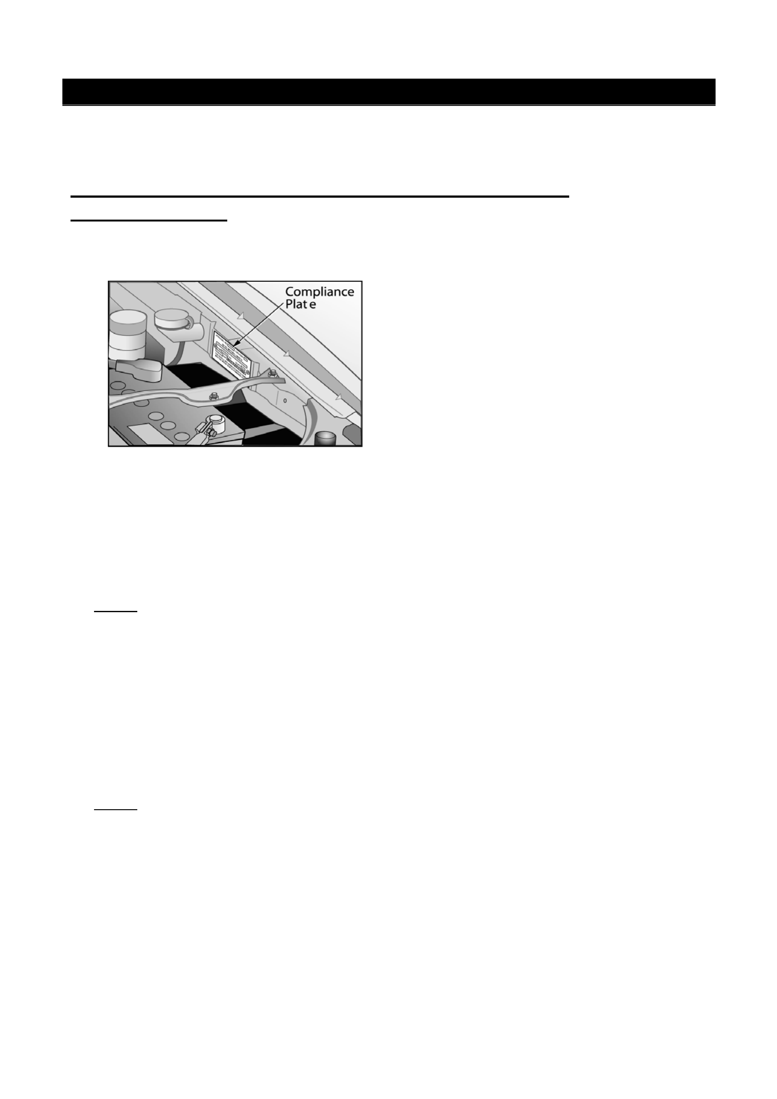
Note: The vehicle Build date shown on the vehicle Compliance Plate must be
used to establish whether the vehicle is affected (requires campaign) or is not
affected.
From: 6G12X14F23L959133 To 6G12X14F83L994307
AND
From: 6G12X14F13L100017 To 6G12X14F33L127459
To determine whether a vehicle is within the affected ISOVIN range, check the ISOVIN
for the critical characters underlined in the ISOVIN range above. The critical
characters refer to the “2” =V2 model, “F” = V8 engine, “3” = model year 2003 (or
Series II) and the Tag number.
VEHICLE LISTINGS
A summary of affected vehicles, shown on Holden’s records, as being delivered to your
Retail premises, is attached to this Bulletin – refer Appendix D.

Page 2 of 12
This listing shows those vehicles with Customer Name and Address details and those
vehicles where no customer details have been forwarded to Holden which may include
unsold (or stock) vehicles.
Where no affected vehicle listing is included with this bulletin, then our records show
your retailer code has not received/sold any affected vehicles.
Please review this listing immediately and mark up with current customer details, if not
included. Write the words “stock vehicle” if listed vehicle is currently in retailer stock.
Please fax or mail the marked-up Affected Vehicle Listing to:
Holden Ltd- Warranty Administration.
Attention: T. Szmyd
Facsimile: (03) 9647 2525
ACTION REQUIRED BY RETAILERS
1. Review the Affected Vehicle Listing (Appendix D), update Customer details not
included and return to Holden Warranty Administration.
2. Check for affected models in Retailer stock and rectify before delivery or transfer.
Please quarantine any stock vehicle/s until the rectification is completed since this
is a potential safety issue.
3. Check the vehicle ISOVIN and if in the affected range, check the Build Date on the
vehicle Compliance Plate of all affected models presented for
• this Recall Campaign action,
• for maintenance servicing,
• warranty repairs or
• for any other reason.
4. If the vehicle is within the affected Build Date range and has not been previously
campaigned (identified by a Campaign 03-H-01 Completed Label on the RHS
‘A’Pillar), then the vehicle requires this Recall Campaign action.
5. Proceed with campaign action as detailed in the Campaign Technical Instructions
attached.
6. Apply a Campaign Completed Label and a Vehicle Service History Label as
specified in the section titled ‘Campaign Completion Identification’.
7. Submit a warranty claim. Refer Warranty Claim Information below.
CUSTOMER NOTIFICATION
Owners of vehicles affected by this recall campaign will be contacted directly by letter
from Holden. Mailing of these letters will commence early July 2003.
The letter provides details of the recall and requests the customer to contact their
Holden Retailer to make a booking to have the appropriate work carried out. Refer to
Appendix A for a draft copy of the Customer Letter.
A campaign notice will appear in the major metropolitan and regional daily newspapers
late next week, advising owners of the requirement for this rectification.

Page 3 of 12
CAMPAIGN COMPLETION IDENTIFICATION
All campaigned vehicles must have:
1. A Campaign Completed label applied to the right hand front ‘A’ pillar, between the
hinges, with details of the campaign:-
Campaign No. “03-H-01”
Retailer Code
Date legibly entered on the label with a permanent ink pen.
AND
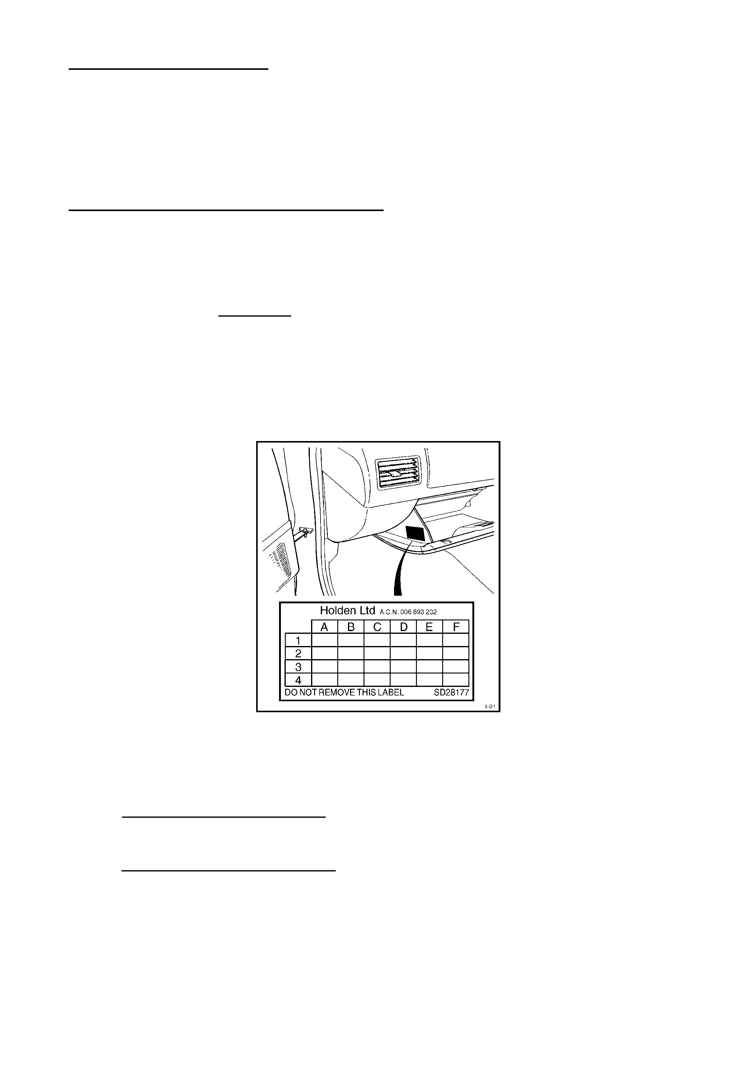
2. For additional identification, place an “X” at the A- 2 co-ordinate of a Vehicle
Service History Label and apply to the inner side of the lower instrument panel
cover.
Extra campaign identification and Vehicle Service History labels are available free of
charge from:
Moore Business Systems
Facsimile: (03) 9270 8925
Phone: (03) 9270 8788
Attention: Mr. Bob Curry
For Campaign Completion Labels Quote stock no. SD 28156 on a Moore Business
Systems ‘packaged goods’ order form for a box of 100 labels.
For Vehicle Service History Labels quote stock no. SD 28177 on a Moore Business
Systems ‘packaged goods’ order form for a box of 100 labels.
PARTS INFORMATION
Each retailer has been sent a quantity of parts kits with this Recall Campaign Bulletin
package.
The kit comprises of a clip and a protective sleeve for fitment to all affected vehicles.
The quantity of kits supplied represents 100% of the vehicles sold by each retailer.
Two kits have also been allocated to each retailer where no affected vehicle has been
sold in case a vehicle is presented for campaign action. Additional parts kits are
available free of charge from Salmat by completing and faxing the Material Order
Form. (Refer to Appendix C).
PART
NUMBER
DESCRIPTION QUANTITY
92145785 03-H-01 Campaign Parts Kit (Clip & Sleeve) 1
In the rare instance where inspection of the wiring harness reveals damage (as defined
in the Technical Instructions) and seat harness replacement is required, order a
replacement from Salmat via the Material Order Form – using Harness part number
92146810.
One replacement harness will be mailed early next week to those Retailers having
received an affected vehicle.
Page 4 of 12
Only order a replacement harness when it has been determined that replacement
is required due to wire strand damage – refer Technical Instructions (Appendix
B).
WARRANTY CLAIM INFORMATION
On completion of campaign action, retailers are requested to IMMEDIATELY submit a
warranty claim using the applicable Recall Campaign Labour Operation Number
specified below. Only claim one of the two Labour Operation Numbers shown below:
Warranty Claim Information
Description: Inspect seat wiring for
damage and fit sleeve and
retainer clip
Replace damaged seat
wiring harness and
install retainer clip
Labour Operation No
Standard Time:
Failure Code:
Case Type
T380401
0.8 Hrs
96
08
T380402
0.9 Hrs
96
08
CONTACT INFORMATION
For further information or clarification on this recall campaign please contact the
relevant person below.
CONTACT NAME CONTACT NUMBER
General enquiries Martha O-Kostidis (03) 9647 1857
Technical enquiries TAS 1800 033 417
Parts related enquiries Salmat (03) 9358 2943
Warranty related inquiries Warranty Administration (03) 9647 2401
Attachments
Appendix A Customer Letter- Draft
Appendix B Campaign Technical Instructions
Appendix C Material Order Form
Appendix D Affected Vehicle Listing

Page 5 of 12
APPENDIX A - Draft – Customer Letter
VEHICLE SAFETY RECALL
03-H-01
Re: Monaro Driver’s Seat Wiring Harness
Dear Holden Customer,
As part of Holden’s ongoing commitment to customer satisfaction and safety, we
have initiated a safety-related recall on Holden Series II CV8 Monaro and HSV
Series II Coupe models, built between December 18, 2002 and May 29, 2003
inclusive.
The wiring harness located beneath the driver's seat may become damaged
during driver adjustment of the seat height or when moving the seat forwards or
backwards.
This may result in an electrical fault which can cause the driver’s seat to move
forwards or backwards unintentionally.
Holden has initiated this campaign to enable us to reposition and positively secure
the wiring harness so that the potential for this damage is eliminated.
Our records show that your vehicle was manufactured within the affected range.
It is therefore necessary for you to contact a Holden Retailer of your choice and
make a booking as soon as possible to have your vehicle reworked. The work
required will be carried out free of charge.
Until this rework is completed on your vehicle, Holden recommends that the
driver’s seat height adjustment is NOT set to the fully “down” position.
If you have any questions regarding this recall, please contact your Holden
Retailer or call the Holden Recall Assistance Line – 1800 632 826 and we will be
pleased to assist you further.
Thank you for your attention to this matter. Please accept our apologies for any
inconvenience this may cause you.
Yours Sincerely
David McMurray
Manager Customer Assistance
Page 6 of 12
APPENDIX B - Campaign Technical Instructions
Follow these steps below to install the protective sleeve to the Driver’s Side Seat
Wiring Harness and fit a clip to the seat frame.
1. Check this modification has not already been performed by inspecting for a 03-H-01
Campaign Completed label or Vehicle Service History label co-ordinate, A-2.
2. Ensure Radio pin number is recorded prior to disconnecting vehicle battery.
3. Drive the seat fully forward (towards the steering wheel), using the electric seat
switches.
4. Adjust the seat to the highest upward position by operating the electric seat
switches.
5. Disconnect the battery to disable the SRS system before proceeding.
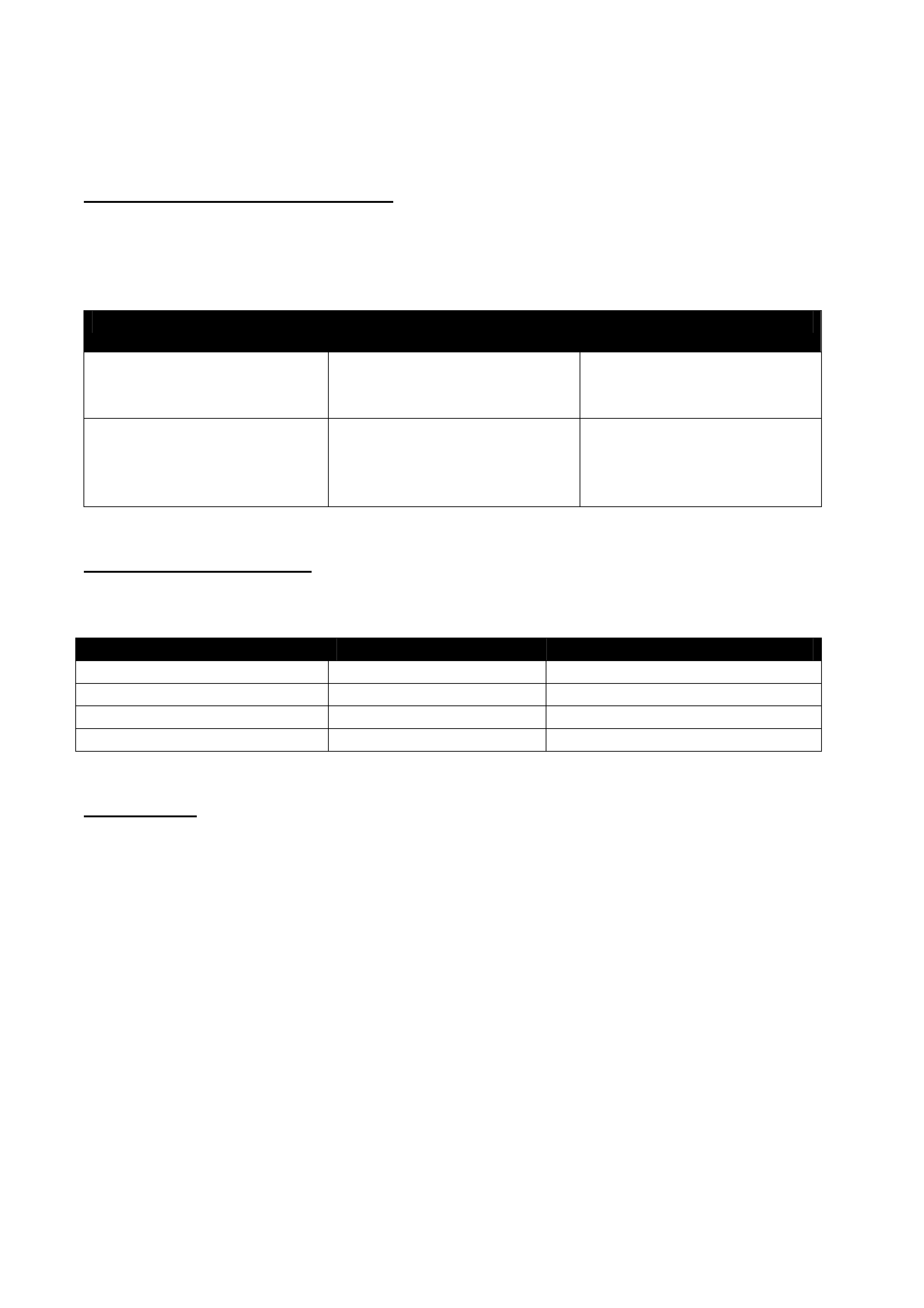
6. Remove the front seat outer cover (Figure 1), refer SIP CD section 1A7-4.3 or refer
to SIP handout attached to the end of these instructions. Lay cover beside seat.
Keep harness connected to cover.
Figure 1
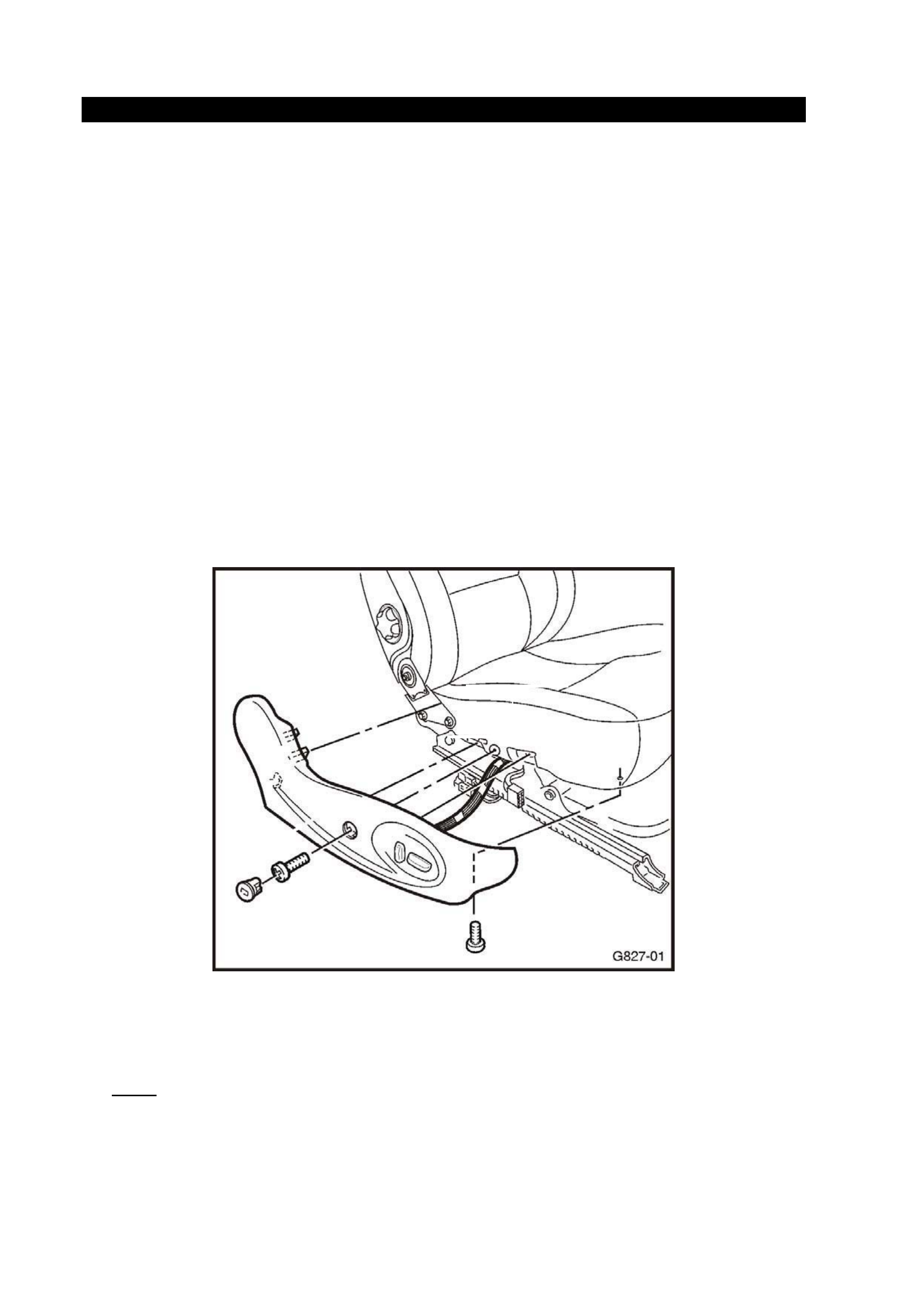
7. Disconnect the wiring secured by the large black metal clip in the side cover. Refer
to Figure 2 overpage.
Gently pull the harness from under the seat.
Note: Some May 2003 built vehicles will have a tie strap fitted to secure the
harness to the seat module. Remove tie strap and discard.
Page 7 of 12
Figure 2
8. Inspect for any harness damage where the harness passes over seat rail.
• If only the wire insulation is damaged, repair by wrapping with electrical
insulation tape.
• If wire strands (copper conductors) are broken within any wires, replace
harness – refer Parts Information in this Bulletin.
Note 1: The replacement harness includes the protective sleeve, however
fitment of the clip to the seat frame is necessary. For Harness routing
instructions, a TAS nominated contact should call Holden’s Technical
Assistance Centre on 1800 033 417.
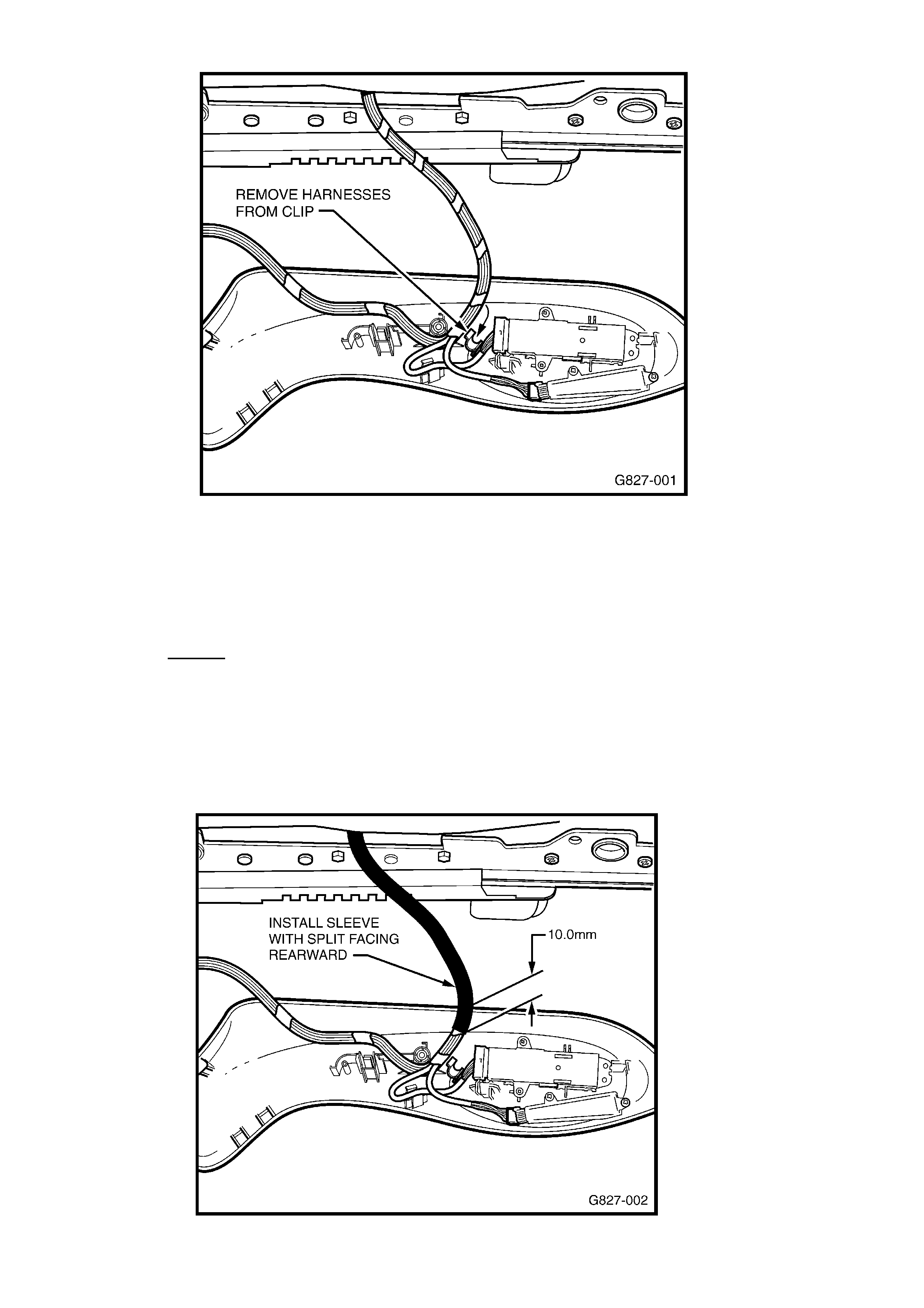
9. Take the 150mm long Black protective sleeve and fit over the wiring harness with
the split section facing rearwards. Ensure that the protective sleeve starts from
10mm within the outer cover lower section. Refer to Figure 3.
Figure 3
Page 8 of 12
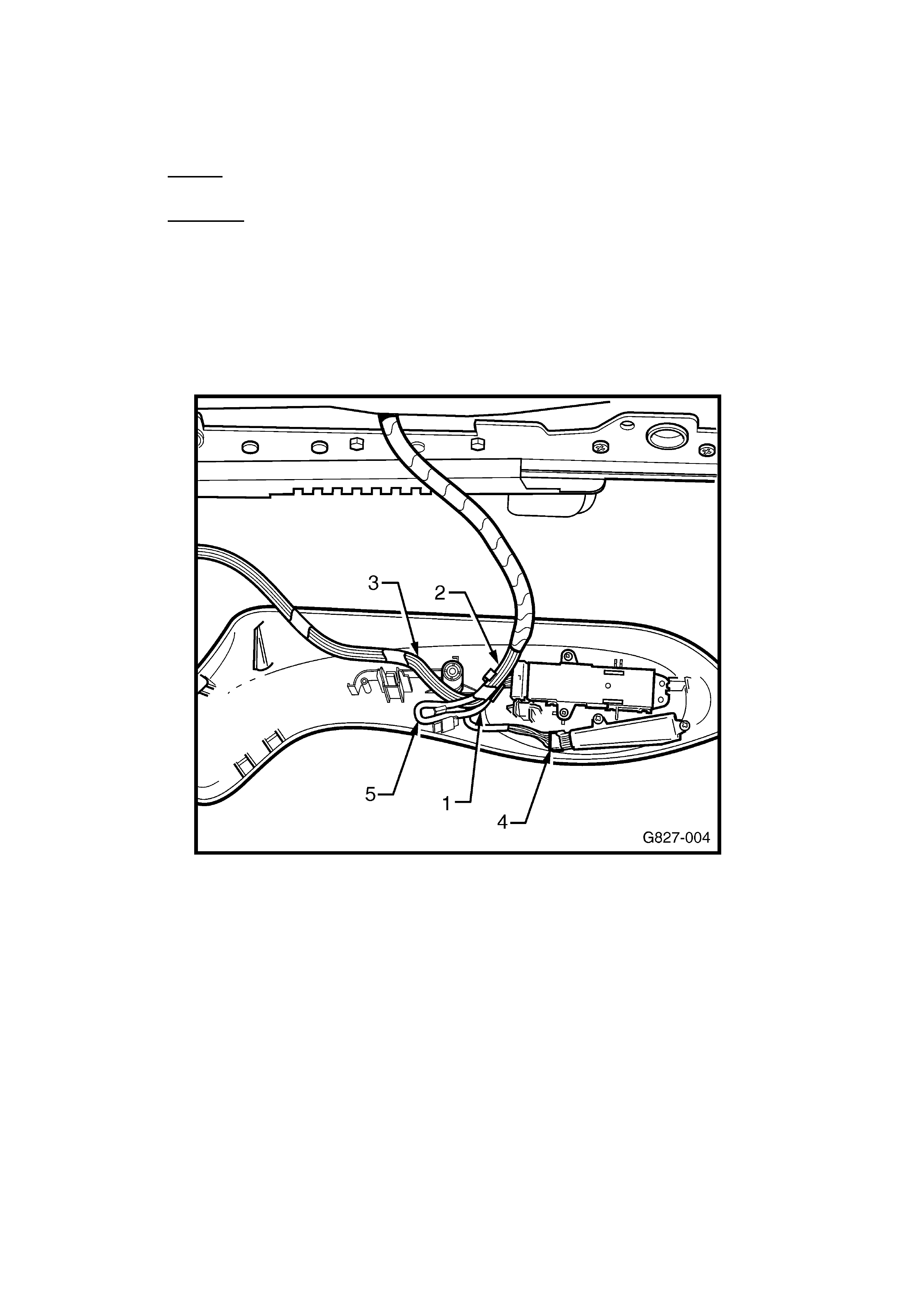
10. Using electrical insulation tape, tightly cover the entire length of the
protective sleeve. Refer Figure 4 below.
11. Install seat wiring harness securely to outer cover noting the following instructions:
• Firstly, clip, the branch of the small harness going to the seat “Mode”
switches into the black metal clip - refer to view (1), Figure 4.
• Secondly, clip main branch of seat wiring harness into black clip on side
cover - refer to view (2), Figure 4.
• Ensure recliner branch of harness (3) is correctly routed around the side
cover mounting post as shown - refer to view (3), Figure 4.
• Ensure memory button switch connector is fully engaged - refer to view (4),
Figure 4.
• Ensure that the harness branch (to the seat switches) is looped correctly and
secured by the smaller bright metal clip - refer to view (5), Figure 4.
Figure 4
12. Move the side outer seat cover as close as possible to the seat track.
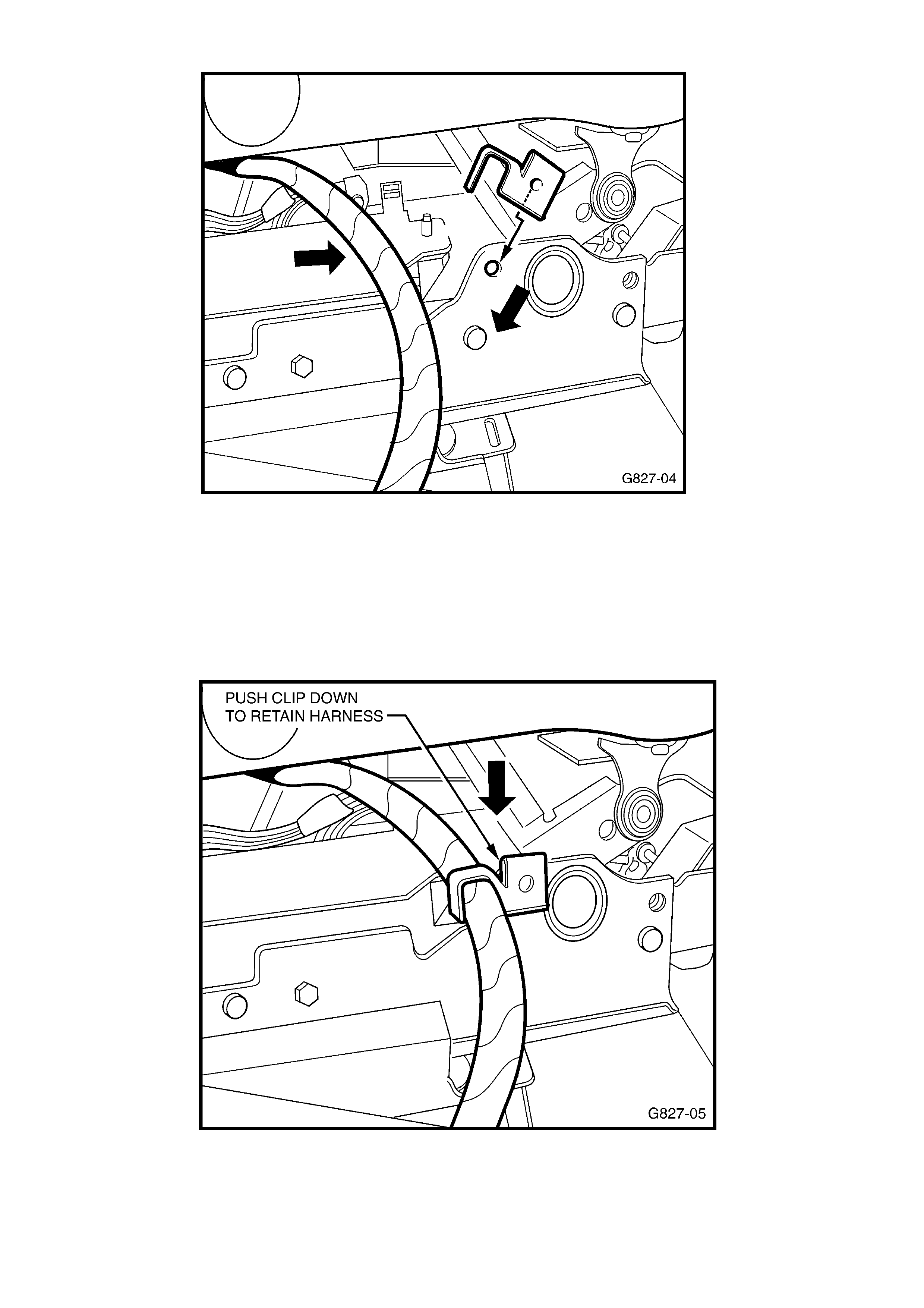
13. Take the metal retaining clip provided in the kit, align with hole and partially insert
onto the seat track frame area as shown in Figure 5 below.
Page 9 of 12
Figure 5
14. Position the protected wiring harness close to the seat track frame so that hook
section of the retaining clip secures the harness.
15. Push the retaining clip downwards until the clip locking mechanism is retained in the
hole on the seat track frame. Refer to Figure 6.
This should position the clip approximately midway along the protective sleeve.
Figure 6
Page 10 of 12
16. Refit the side seat outer cover ensuring that the harness is routed correctly, as per
Figure 4. Refer to SIP CD section 1A7-4.3.
Caution: Care must be taken to avoid any damage to the plastic trims.
17. Reconnect battery to enable SRS system.
18. Check for correct operation of seat travel in all modes.
19. Ensure radio is operational.
20. END OF PROCEDURE.
Extract Of SIP Instructions
4.3 FRONT SEAT OUTER SIDE COVER
LT Section No. – 14-322
IMPORTANT: If the seat assembly is to be dissembled, adjust the seat assembly to its highest position before disconnecting
the power to the seat.
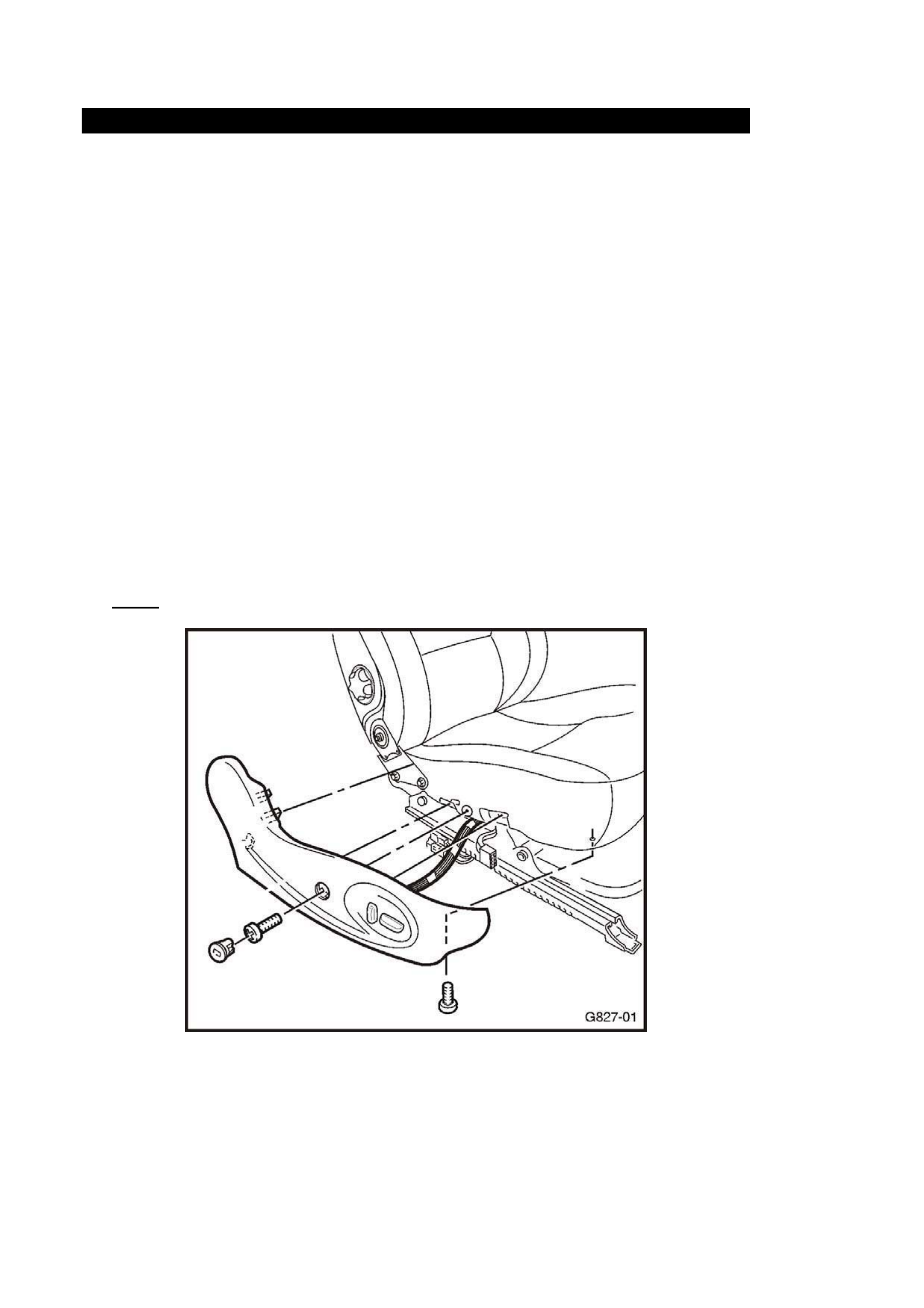
Remove
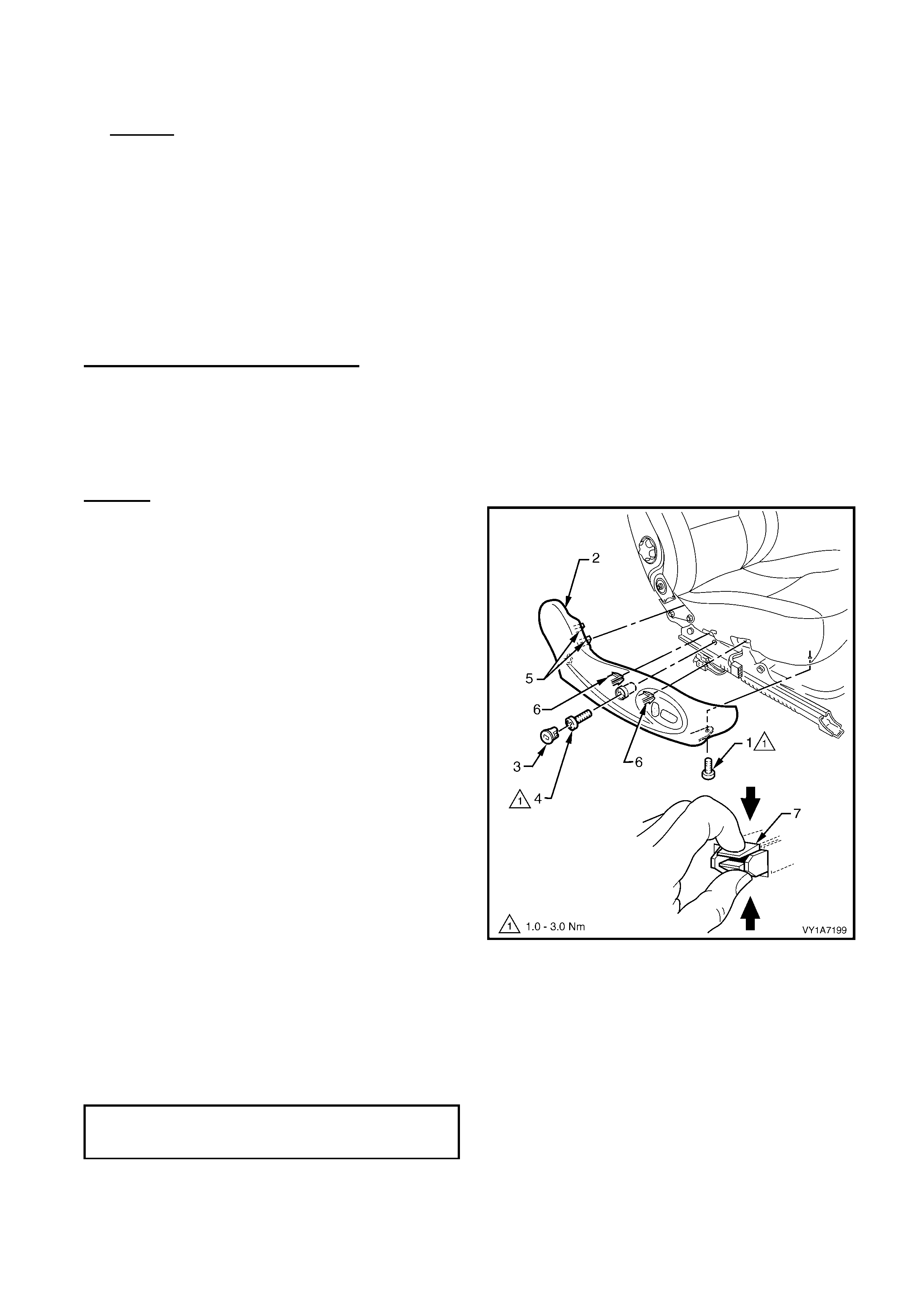
1. Remove the screw (1) from the front of the outer
side cover (2).
2. Remove the front seat outer side cover plug (3) by
rotating the plug anti-clockwise, one quarter of a
turn.
TIP: A fine screwdriver, would be useful to aid the
removal of the side cover plug without damage.
3. Remove the screw (4) located behind the plug.
4. Gently pull the outer cover away from the seat-
back recliner to disengage the two clips (5)
attached to the recliner frame.
5. Reach up under the seat assembly and squeeze
together the two retaining tangs (6), on the inner
side of the outer cover while gently pulling the
outer cover.
NOTE: Only remove the outer cover far enough away
from the seat cushion assembly to gain access to the
seat wiring harness connectors.
Figure 1A7-1
Install
Reinstallation of the front seat outer side cover is the reverse
of the removal procedure, noting the following:
1. Ensure all fasteners are tightened to the correct torque
specification.
FRONT OUTER SIDE COVER
ATTACHING SCREW
TORQUE SPECIFICATION 1.0 – 3.0 Nm

Page 11 of 12
APPENDIX C – SALMAT MATERIAL ORDER FORM
SAFETY RECALL CAMPAIGN- 03-H-01
Installation of Protective Sleeve and Retainer Clip on Seat Wiring Harness
V2 Monaro Series II CV8 & HSV Series II Coupe
PLEASE TAKE NOTE: SALMAT HAS A NEW FAX NUMBER!!
Fax this form to SALMAT ON: (03) 9358 – 2999
This retailer wishes to order additional stock of parts in quantities as listed below
(ISOVINs not required).
PART
NUMBER DESCRIPTION QTY Req’d
92145785 03-H-01 Campaign Parts Kit (Clip & Sleeve)
Note:
In the rare instance that a driver’s seat harness is required, then order a replacement
via this form (maximum one only)
• Holden will investigate each case where a harness is requested
• Prepare damaged harness for return to Repac for Holden’s investigation.
PART
NUMBER DESCRIPTION QTY
92146810 Driver’s Seat Harness (Only order if harness
has broken wire strands – refer Technical
Instructions).
Retailer Code: ______________________ Date: ___________________
Retailer Name: ______________________ Ph. No: __________________
Retailer Address: _______________________________________________
Contact Name: _______________________ Fax No: _________________
SALMAT USE ONLY
Retailer Order Acknowledgement Details (fax back to Retailer same day)
Confirmation of parts order received by Salmat on: __________________
Quantity requested despatched YES / NO (Please circle )
Date dispatched ______________________
Freight forward agent ______________________
Consignment Note Number _____________________

Page 12 of 12
APPENDIX D – Affected Vehicle Listing
A summary of affected vehicles, shown on Holden’s records, as being delivered to your
Retail premises, is attached to the Service Managers copy of the Campaign Bulletin.
This listing shows those vehicles with Customer Name and Address details and those
vehicles where no customer details have been forwarded to Holden which may include
unsold (or stock) vehicles.
Where no affected vehicle listing is included with this bulletin, then our records show
your retailer code has not received/sold any affected vehicles.
Please review this listing immediately and mark up with current customer details, if not
included. Write the words “stock vehicle” if listed vehicle is currently in retailer stock.
Please fax or mail the marked-up Affected Vehicle Listing to:
Holden Ltd- Warranty Administration.
Attention: T. Szmyd
Facsimile: (03) 9647 2525

PRODUCT CAMPAIGN BULLETIN
03-H-02
October 28, 2003
SUBJECT: REPLACEMENT OF INCORRECT COMPLIANCE PLATE
MODELS AFFECTED: RA RODEO
This bulletin announces the initiation of a safety recall campaign to install
the correct compliance plate to some RA Rodeo model vehicles.
DESCRIPTION OF DEFECT
There have been some RA Rodeo vehicles retailed where the compliance
plate has incorrect information in regard to the seating capacity of the
vehicle.
To correct this situation, Holden has initiated this recall action to ensure
that every affected vehicle is updated to include the correct compliance
plate in accordance with the Australian Design Rule requirements.
AFFECTED VEHICLES
The affected vehicles are as per the list in Appendix A.
ACTION REQUIRED BY DEALERS
1.
2.
3.
4.
5.
6.
7.
8.
9.
Confirm vehicle VIN is affected by checking list as per Appendix A.
Confirm vehicle has not previously been reworked. (ie Identified by an
‘X’ in the A-2 co-ordinate of the “Vehicle Service History” label or
application of “03-H-02 Campaign Completed” label).
If vehicle has not been reworked, proceed with campaign.
Organise a vehicle booking. (Allow 5 days for shipping of the
replacement compliance plate)
Request the replacement compliance plate from SALMAT using the
Salmat Material Order Form. Note: Booking date will be required to
order a replacement compliance plate. Refer to Appendix C.
Remove originally installed compliance plate and install plate supplied
by Salmat. Refer Replacement Instruction Appendix D.
Affix a Campaign Completed Label and a Vehicle Service History Label
as specified in the section titled ‘Campaign Completion Identification’.
Return incorrectly stamped (replaced) compliance plate immediately to
Salmat in the supplied pre-paid satchel.
Submit a warranty claim. Refer “Warranty Claim Information”.
CUSTOMER NOTIFICATION
Owners of vehicles affected by this recall campaign will be contacted directly by letter from
Holden.
The letter provides details of the recall campaign and requests the customer to contact their
Holden Retailer to make a service booking to have the appropriate work carried out. Refer
to Appendix B for a draft copy of the customer letter.
CAMPAIGN COMPLETION IDENTIFICATION
All campaigned vehicles must have:
1. A Campaign Completed label applied to the right hand front ‘A’ pillar, between the
hinges, with details of the campaign, 03-H-02, Dealership code and date legibly entered
on the label with a permanent ink pen.
AND
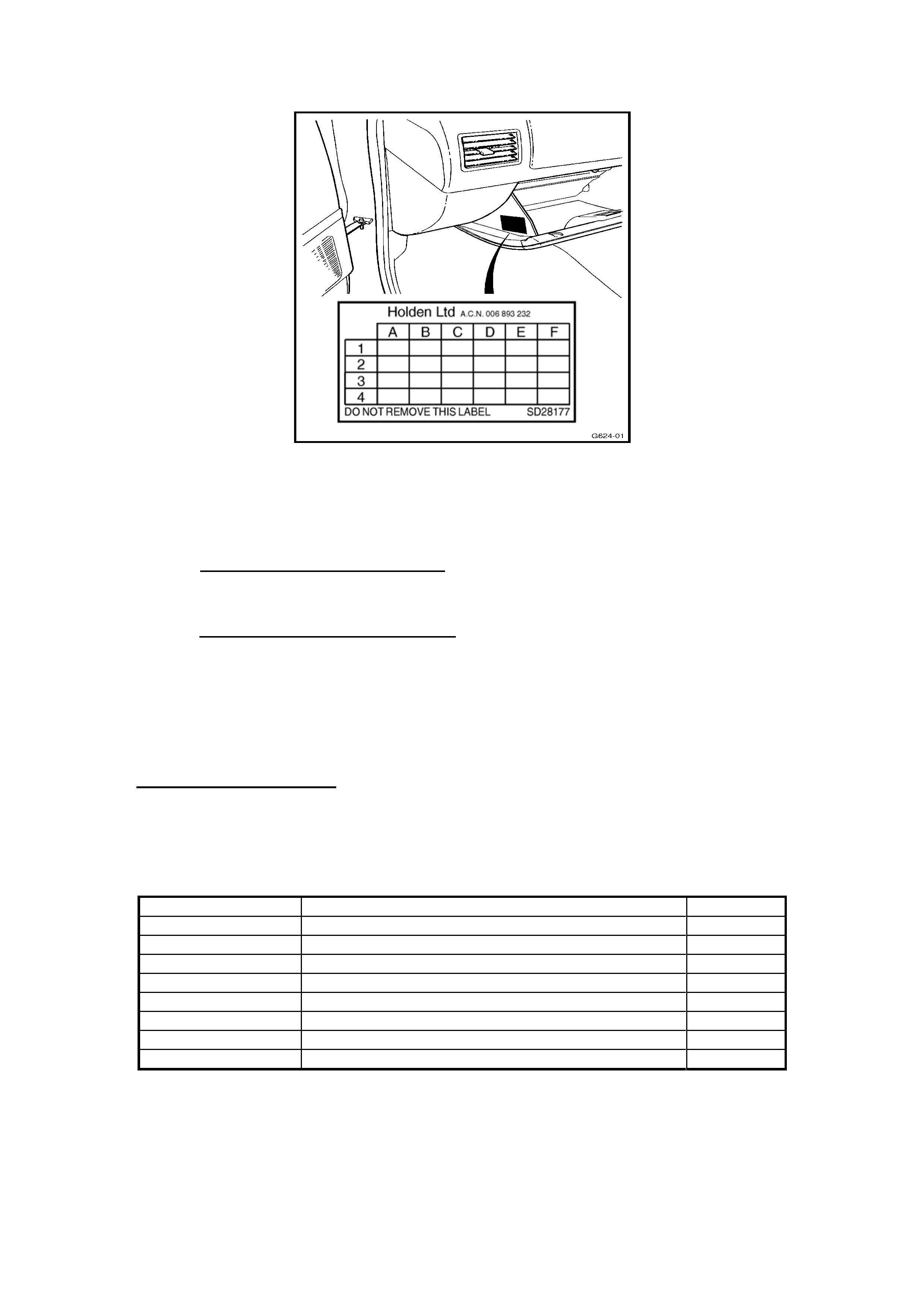
2. For additional identification, mark an “X” at the A-2 co-ordinate of a Vehicle Service
History Label and apply to the outer edge on the left-hand side of the glovebox. Refer to
Figure 2 below.
X
Figure 2
Extra Campaign Completed and Vehicle Service History labels are available free of charge
from Moore Business Systems.
• For Campaign Completed Labels Quote stock no. SD 28156 on a Moore Business
Systems ‘Packaged Goods’ order form for a pack of 100 labels.
• For Vehicle Service History Labels quote stock no. SD 28177 on a Moore Business
Systems ‘Packaged Goods’ order form for a pack of 100 labels.
Fax the order form to Moore Business Systems on Facsimile: (03) 9270 8925
Should you need to follow-up on a placed order, contact Liz Papalambidis on telephone
number (03) 9270 8788.
10/03/04
3of 7
PARTS INFORMATION
A specific replacement compliance plate is available for each affected vehicle. Once a
customer booking is made, order the replacement Compliance Plate for the booked vehicle
by completing the Material Order Form, (refer to Appendix C) and faxing it to SALMAT. The
fax number is shown on the Material Order form.
The replacement compliance plate will be forwarded to your retailer premises by
“Registered Mail.” Please note that to maintain Compliance Plate security, the person
requesting the replacement plate will be required to sign for receipt of the plate at the
delivery address (retailer premises) or at the local Post Office if unavailable to sign at the
Retailer premises.
Once received, store the replacement plate in a safe and secure location to avoid loss or
damage.
WARRANTY CLAIM INFORMATION
On completion of campaign action, retailers are requested to submit a warranty claim using
the Labour Operation Number specified below.
Warranty Claim Information
Description
Replace Compliance Plate
Labour Operation No.:
Standard Time:
Failure Code:
Case Type:
T380501
0.5 hours
96
08
CONTACT INFORMATION
For further information or clarification on this recall campaign please contact the relevant
person below.
CONTACT NAME CONTACT NUMBER
General enquiries Alex Holt
Gary Brunet
(03) 9647 7619
(03) 9647 2463
Parts related enquiries Salmat (03) 9358 2990
Warranty related enquiries Warranty Administration (03) 9647 2401
J. K. Hoffman
General Service Manager
Attachments
Appendix A Affected Vehicle List
Appendix B Customer Letter- Draft
Appendix C Material Order Form
Appendix D Replacement Instruction

10/03/04
4of 7
APPENDIX A – Affected Vehicle List
MPATFR32J4H500135 MPATFS77J4H500511 MPATFS77J4H503401
MPATFR26J4H500203 MPATFS77J4H500515 MPATFS77J4H503402
MPATFR26J4H500204 MPATFR26J4H500516 MPATFS77J4H503404
MPATFR26J4H500208 MPATFS77J4H500540 MPATFR26J4H503450
MPATFR26J4H500211 MPATFS77J4H500541 MPATFR26J4H503451
MPATFR26J4H500215 MPATFS77J4H500542 MPATFR26J4H503595
MPATFR26J4H500231 MPATFR26J4H500543 MPATFR32J4H503682
MPATFR26J4H500241 MPATFS77J4H500544 MPATFR32J4H503725
MPATFR26J4H500255 MPATFS77J4H500545 MPATFS77J4H503727
MPATFR26J4H500256 MPATFS77J4H500546 MPATFS77J4H503731
MPATFR26J4H500260 MPATFS77J4H500548
MPATFR26J4H500261 MPATFR26J4H500549
MPATFR26J4H500277 MPATFR26J4H500550
MPATFR26J4H500279 MPATFR26J4H500552
MPATFR26J4H500292 MPATFR26J4H500553
MPATFR26J4H500311 MPATFR26J4H500555
MPATFR26J4H500314 MPATFR26J4H500558
MPATFR26J4H500315 MPATFR26J4H502546
MPATFR26J4H500323 MPATFR26J4H502551
MPATFR26J4H500324 MPATFS26J4H502565
MPATFR26J4H500325 MPATFR26J4H502616
MPATFR26J4H500326 MPATFS26J4H502630
MPATFR26J4H500331 MPATFR26J4H502632
MPATFR26J4H500332 MPATFR26J4H502675
MPATFS77J4H500334 MPATFR26J4H502737
MPATFR26J4H500348 MPATFR26J4H502790
MPATFS77J4H500350 MPATFR26J4H502846
MPATFS77J4H500353 MPATFR26J4H502868
MPATFS77J4H500357 MPATFR26J4H502877
MPATFS77J4H500359 MPATFR26J4H502905
MPATFS77J4H500367 MPATFR26J4H502915
MPATFS77J4H500376 MPATFR26J4H502922
MPATFS77J4H500380 MPATFR26J4H502927
MPATFS77J4H500389 MPATFR26J4H502977
MPATFS77J4H500414 MPATFR26J4H503028
MPATFS77J4H500425 MPATFR77J4H503049
MPATFS77J4H500431 MPATFR26J4H503078
MPATFR26J4H500434 MPATFS77J4H503081
MPATFR26J4H500438 MPATFS77J4H503099
MPATFS77J4H500442 MPATFR26J4H503105
MPATFS77J4H500448 MPATFR26J4H503180
MPATFS77J4H500452 MPATFR26J4H503182
MPATFS77J4H500456 MPATFR26J4H503194
MPATFS77J4H500459 MPATFR26J4H503234
MPATFS77J4H500466 MPATFS77J4H503320
MPATFS77J4H500471 MPATFS77H4H503345
MPATFS77J4H500472 MPATFR77J4H503389
MPATFS77J4H500473 MPATFR26J4H503395
MPATFS77J4H500474 MPATFR26J4H503397
MPATFS77J4H500478 MPATFS77J4H503398
NOTE:
This affected vehicle listing
is sorted in serial number
sequence in ascending
order.
Read the last 6 digits to
quickly find or confirm an
affected vehicle

10/03/04
5of 7
APPENDIX B - Draft – Customer Letter
VEHICLE SAFETY RECALL
Dear Holden Customer,
As part of Holden’s ongoing commitment to customer satisfaction, we have initiated
a Vehicle Recall Campaign affecting some RA Rodeo model vehicles.
Holden has been made aware that an incorrect compliance plate has been fitted to
some of these vehicles.
In these cases the compliance plate does not specify the correct seating capacity
for the vehicle. It is an Australian Design Rule requirement that the seating
capacity information is on the compliance plate.
To ensure the compliance plate includes the correct seating capacity for your
vehicle, the compliance plate needs to be replaced.
Our records show that your Holden vehicle was manufactured with the incorrect
compliance plate. It is therefore necessary for you to make a booking, at your
convenience, with a Holden Retailer of your choice to have the correct compliance
plate fitted.
Work will be carried out free of charge and can be completed while you wait,
provided the necessary arrangements have been made with a Holden Retailer.
If you should have any questions, please contact your retailer or call the Holden Recall
and Rework Assistance Centre on 1800 632 826, where we will be pleased to assist.
Thank you for your attention to this matter. Please accept our apologies for any
inconvenience caused to you.
Yours Sincerely
David McMurray
Manager Customer Assistance

10/03/04
6of 7
APPENDIX C – SALMAT MATERIAL ORDER FORM
RECALL CAMPAIGN 03-H-02
RA Rodeo Compliance Plate Replacement
Fax This Form To: Salmat - (03) 9358 2999
Please supply the replacement RA Rodeo Compliance Plate for the vehicle shown below
IMPORTANT: Only order parts when a customer has supplied the ISO VIN and confirmed a
booking date. ONLY 1 compliance plate can be ordered per Order Form.
Date _____________________
Retailer Code: _____________ Retailer Name:________________________
Retailer Address: _______________________________________________
Ph. No _________________________Fax No:_________________________
Name of person to receive
replacement Compliance Plate ______________________________
Via Registered Mail (Please print name clearly)
Vehicle ISOVIN Customer Booking Date
SALMAT USE ONLY
Retailer Order Acknowledgement Details (fax back to retailer same day)
Date Order Received Date Dispatched ___________________
Replacement
Compliance Plate
10/03/04
7of 7
APPENDIX D – REPLACEMENT INSTRUCTION
RA RODEO COMPLIANCE PLATE REPLACEMENT
INSTRUCTIONS
1. Locate compliance plate as per the diagram below.
COMPLIANCE PLATE
Riveted to the LH inner guard.
Displays approval numbers, category,
manufacturer’s name, model name and
code, Gross Vehicle Mass (GVM), seating
capacity, build date and V.I.N.
2.
3.
Check to confirm that the supplied replacement Compliance Plate shows the correct VIN
of the vehicle – check all 17 digits
The Compliance plate is fixed to the vehicle body inner guard by two 3.2mm rivets that
will need to be drilled out to remove the incorrectly stamped plate.
NOTE: Drill head off pop rivet only – DO NOT drill into vehicle sheet metal
4.
5.
6.
Affix the supplied replacement compliance plate with the two rivets supplied with the
replacement compliance plate ( An extra rivet is supplied as a spare in the event a rivet
does not secure correctly).
With tin snips, Cut the replaced compliance plate in two through the vertical (up and
down) - Not across the length.
Send both halves of cut compliance plate to SALMAT in the supplied pre-paid Satchel.
NOTE: Salmat has been instructed to follow-up retailers failing to return replaced plates
promptly. Please ensure that the replaced plate is returned to Salmat immediately it is
removed

PRODUCT CAMPAIGN BULLETIN
03-H-03
December 5, 2003
SUBJECT: INJECTOR SLEEVE AND O-RING REPLACEMENT
MODELS AFFECTED: 1998MY-2000MY UBS JACKAROO DIESEL
ENGINES (4JX1-TC)
This bulletin announces the initiation of a SAFETY RELATED recall campaign
to replace the injector sleeves and O-rings located in the cylinder head of the
4JX1 diesel engine.
The Sleeve Replacement Procedure discussed in Retailer letter RL72/02 has
been upgraded to a safety related recall campaign. Vehicles that have been
previously reworked via DL 72/02 procedures and are identified in Appendix
“C”, DO NOT REQUIRE THIS CAMPAIGN ACTION.
DESCRIPTION OF DEFECT
The injector sleeve sealing (O-rings) material can deteriorate and cause fuel
to leak into the crankcase.
This may result in an unintentional increase in engine speed, and possibly
vehicle speed.
AFFECTED VEHICLES
The affected vehicles are 1998 to 2000 model year Jackaroos fitted with the
4JX1-TC diesel engine built before engine number 676517 (October 1999).
Refer to the table below for affected vehicle ISOVINS by model year.
Model
Year
From To Comments
1998 JACUBS73GW7100010 JACUBS73GW7103492 Inclusive
1999 JACUBS73GX7100566 JACUBS73GX7104876 Inclusive
2000 JACUBS73GY7100012 JACUBS73GY7102028 Inclusive
Note 1: There are 3 separate model year ranges of ISOVINS affected. Refer
to the tenth (10th) character in the ISOVIN for the model year reference i.e.
W=1998, X=1999 and Y=2000.
Page 1 of 21

Note 2: Vehicles shown on the list of previously reworked vehicles (See
Appendix C) DO NOT REQUIRE this campaign action. If the engine number is
676517 or greater then campaign action is also not required.
On presentation of the vehicle considered by the customer to be affected by
this campaign, follow this flow chart to determine the action required.
Page 2 of 21
Start
NO
YES
YES
NO
Is the
Vehicle on the
previous
Rework list? Refer to
Attachment C of the Product
Campaign
Bulletin.
NO
Vehicle is affected and requires
campaign action.
Vehicles not affected or have been
already reworked.
YES
NO YES
Is there a 03-H-03
Campaign Completed Label on
RH “A” pillar, and a Service History
Label with the C2 coordinate
marked with an X on
the glove box? Refer
Campaign Completion I.D.
Is the engine number
Less than 676517?
Is the
Vehicle in the affected
Range? Refer to Affected Vehicles
table on page 1 in the Product
Campaign
Bulletin.

ACTION REQUIRED BY RETAILERS
1. Check all vehicles presented to the retail premises for any reason to
identify the need for the campaign to be performed.
2. If the vehicle is affected and has not been previously campaigned
(identified by a Campaign 03-H-03 Completed Label on the RHS ‘A’Pillar),
or reworked (identified by Appendix C list) then the vehicle requires this
Recall Campaign action.
3. Proceed with campaign action as detailed in the Campaign Technical
Instructions attached. Note: A special tool is required to remove the injector
sleeves from the cylinder head. This special tool was supplied to all
retailers in 2002 with Retailer Letter RL72/02. Retailers are encouraged to
immediately locate the special tool (refer Fig 6). Note: contact Brett Fowler
on (03) 96 47 18 57 should a replacement special tool be required.
4. Apply a Campaign Completed Label and a Vehicle Service History Label as
specified in the section titled ‘Campaign Completion Identification’.
5. Submit a warranty claim. Refer Warranty Claim Information below.
CUSTOMER NOTIFICATION
Owners of vehicles affected by this recall campaign will be contacted directly
by letter from Holden. Mailing of these letters will commence mid December
2003.
The customer letter provides details of the recall and requests the customer to
contact their Holden Retailer to make a booking to have the appropriate work
carried out. Refer to Appendix A for a draft copy of the Customer Letter.
CAMPAIGN COMPLETION IDENTIFICATION
All campaigned vehicles must have:
1. A Campaign Completed label applied to the right hand front ‘A’ pillar,
between the hinges, with details of the campaign, 03-H-03, Retailer Code
and Date legibly entered on the label with a permanent ink pen.
AND
2. For additional identification, mark an “X” at the C2 –coordinate of vehicle
Service History Label and apply to the outer edge on the left-hand side of
the glovebox. Refer to Figure 2 below. Note: Check driver’s side “A” pillar
for any previous Service History label. If a Service History label is present
on the “A” pillar record information shown on it, on the new label on the
glovebox. Then remove old Service History label from the “A” pillar.
Page 3 of 21
X
Figure 2
Extra Campaign Completed and Vehicle Service History labels are available
free of charge from Moore Business Systems.
• For Campaign Completed Labels Quote stock no. SD 28156 on a Moore
Business Systems ‘Packaged Goods’ order form for a pack of 100 labels.
• For Vehicle Service History Labels quote stock no. SD 28177 on a Moore
Business Systems ‘Packaged Goods’ order form for a pack of 100 labels.
Fax the order form to Moore Business Systems on Facsimile: (03) 9270 8925
Should you need to follow-up on a placed order, contact Moore customer
service on telephone number (03) 9270 8788.
PARTS INFORMATION
Each retailer has been sent an initial quantity of 2 parts kits with this Recall
Campaign Bulletin package.
Each kit comprises of the following parts:
Part No: Description: Qty Per Kit
8971757830 Gasket – Injector Nozzle Clamp 4
8972407980 O-Ring Injector Nozzle 4
8971611092 Gasket – Injector Nozzle Clamp 4
8971842160 Gasket Oil Pipe 2
8971606721 Gasket – Cover to Cylinder Head 1
8972451850 Sleeve – Injector 4
8972229330 Gasket- Inlet Pipe 1
8971378200 Gasket – T/V 1
Additional parts kits are available free of charge from Salmat by completing
and faxing the Material Order Form. (Refer to Appendix D). Salmat will send
written confirmation acknowledging receipt of the Material Order Form plus
dispatch details within 1 working day of receipt. Confirm receipt of Material
Page 4 of 21
Order Form by Salmat if written confirmation of receipt not received within 24
hours.
Part
Number
Description Quantity
03-H-03 Injector Sleeve and Seal
kit
1
WARRANTY CLAIM INFORMATION
On completion of campaign action, retailers must IMMEDIATELY submit a
warranty claim using the applicable Recall Campaign Labour Operation
Number specified below:
Description: Injector Sleeve O-ring
Labour Operation No
Standard Time:
Failure Code:
Case Type
T380601
3.0 Hrs
96
08
Note: Additional time has been incorporated in the standard time to ensure
affected vehicles requiring this campaign action are prioritised so that vehicles
are completed and returned to customers as soon as possible.
CONTACT INFORMATION
For further information or clarification on this recall campaign please contact
the relevant person below.
CONTACT NAME CONTACT NUMBER
General enquiries Gary Brunet (03) 9647 2463
General enquiries Brett Fowler (03) 9647 1857
Technical enquiries TAS 1800 033 417
(press 2 for LCV)
Parts related enquiries Salmat (03) 9358 2990
Warranty related inquiries Warranty Administration (03) 9647 2401
Attachments
Appendix A Customer Letter- Draft
Appendix B Campaign Technical Instructions
Appendix C Affected Vehicle Listing
Appendix D Material Order Form
Page 5 of 21

APPENDIX A - Customer Letter
VEHICLE SAFETY RECALL
03-H-03
Re: Jackaroo Diesel Fuel Injector O’ring Replacement
Dear Holden Customer,
As part of Holden’s ongoing commitment to customer satisfaction and safety, we have
initiated a safety-related recall on model year 1998 to 2000 Holden Jackaroo vehicles
with Diesel Engine.
Holden has become aware that the fuel injector sealing o’rings and sleeve o’rings in
the cylinder head, may deteriorate and potentially allow fuel to leak into the engine
crank case.
In cases where a leak has developed, the vehicle may experience an unintended
increase in engine speed, and possibly vehicle speed.
Our records show your Holden vehicle was manufactured within the affected range. It
is therefore necessary for you to contact a Holden Retailer of your choice and make a
booking as soon as possible to have the affected injector seals and associated parts
replaced. The work required will be carried out free of charge.
If you have any questions regarding this recall, please contact your Holden Retailer or
call the Holden Recall and Rework Assistance Centre on 1800 632 826 and we will be
pleased to assist you further.
Thank you for your attention to this matter. Please accept our apologies for any
inconvenience caused to you.
Yours sincerely
David McMurray
Manager Customer Assistance
Page 6 of 21
APPENDIX B - Campaign Technical Instructions
The instructions provided below vary to those previously provided in SIP and Service
Techlines. Please read these instructions thoroughly to ensure the recall campaign
action is carried out precisely as intended.
1. Disconnect the battery negative (-) cable/s (ensure the radio security PIN is
available).
2. Remove the front cross member protector and drain 5 litres of coolant into a clean
container (to be reused). This prevents coolant filling the combustion chamber
when the injector sleeves are removed.
Section 1 : Remove the cylinder head cover.
3. Remove rubber intercooler surround, throttle body retaining nuts, front intercooler
bracket bolt at the engine on the left hand side and intercooler bracket bolts at the
intercooler on the right hand side.
4. Loosen the turbo to intercooler hose at the intercooler end.
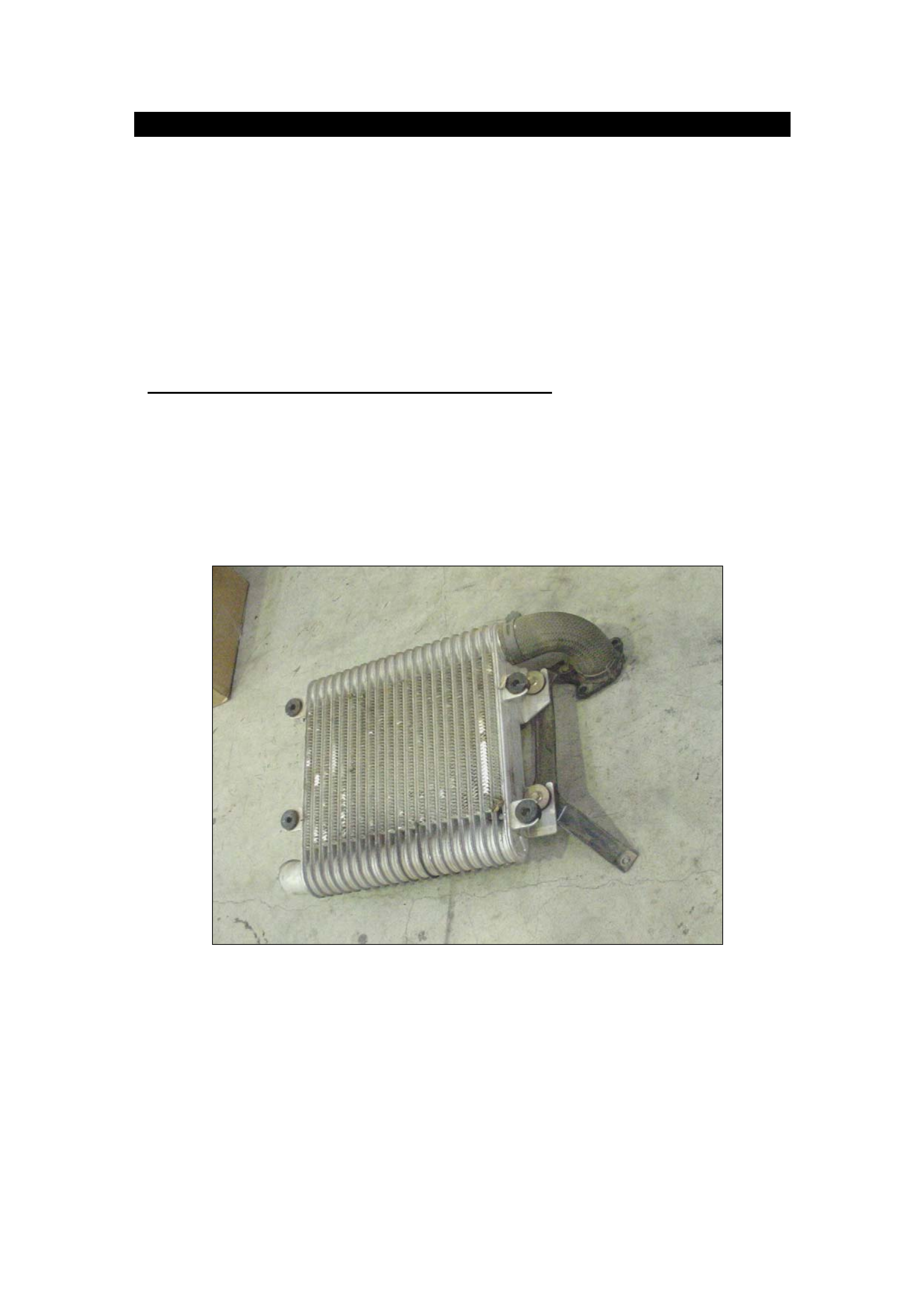
5. Remove the intercooler, throttle body to intercooler hose and throttle body flange
as one assembly (Fig 1).
Figure 1
NOTE: Cover the manifold and turbo with clean rags to prevent foreign
material entry.
6. Disconnect throttle body harness connectors and remove the throttle body.
7. Remove the air intake duct mounting bolts, PCV hose (at the cylinder head),
vacuum hoses, turbo clamp, air cleaner service clips and remove the air intake
duct with air cleaner element attached (Fig 2).
Page 7 of 21
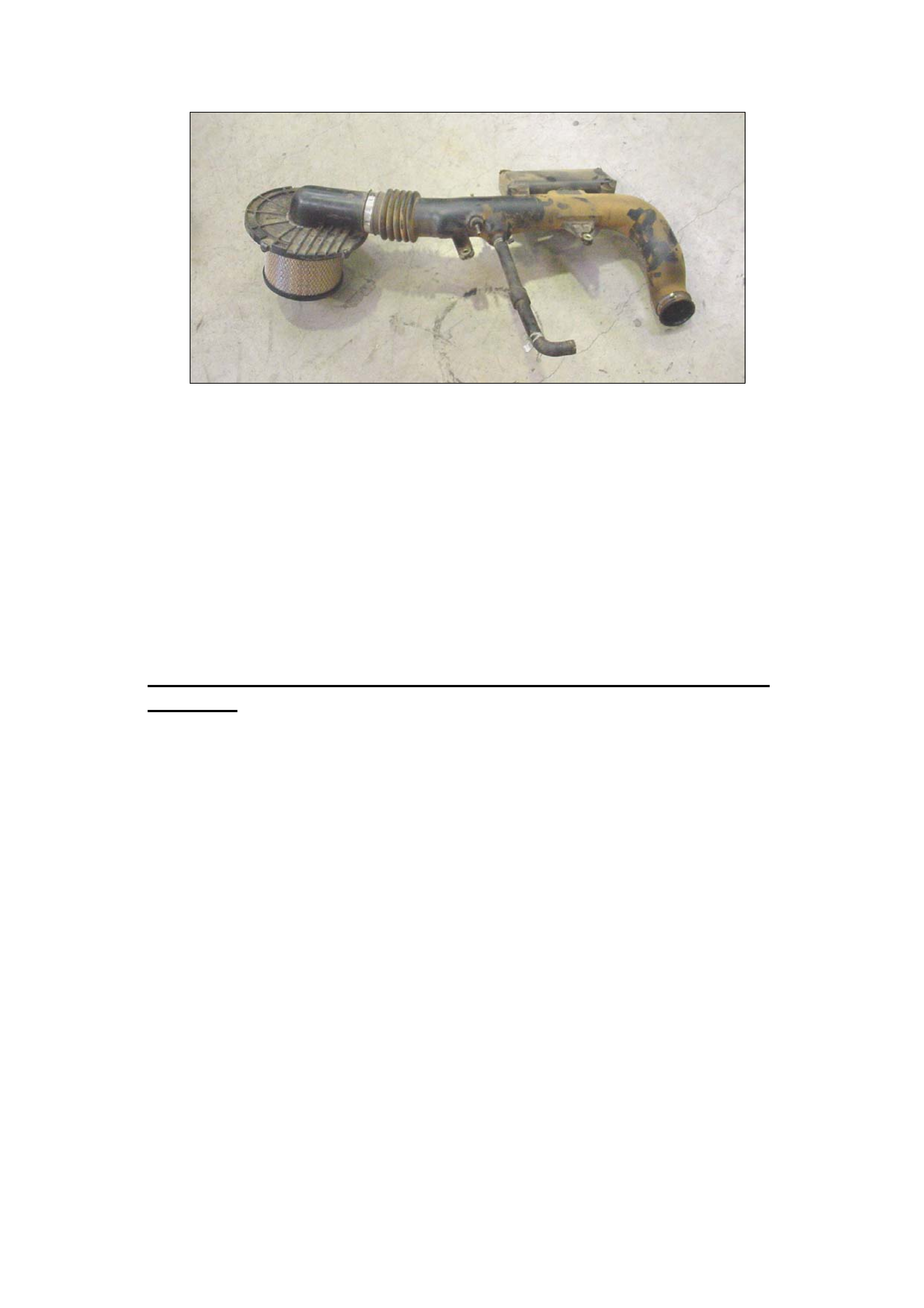
Figure 2
8. Remove bolts and nuts from the cylinder head cover insulator
9. Remove PVC hose at the rear of the engine.
10. Remove the engine insulation cover and foam from the cylinder head cover and
inlet manifold. Note: Take care not to lose retaining bolt spacers when removing
the cover.
11. Place a rag around the lower high pressure oil pipe fitting and loosen,
completely remove the pipe.
NOTE: A rag must be used to restrict the escape of any residual high pressure
and to prevent oil draining onto other engine components.
12. Remove the cylinder head cover bolts and the cylinder head cover.
Section 2: Remove the injectors, oil rail and injector harness as one
assembly.
NOTE : Do not disconnect the injector harness from the oil rail or
injectors as this may cause connector breakage.
13. Remove the oil rail drain plug at the right hand front of the oil rail and allow the oil
to drain.
NOTE: Clear any drained oil from around the injector to prevent oil running
into the combustion chamber.
14. Remove bolts and nuts from the oil rail, injector H-Clamp nuts and washers and
injector harness retaining bolts.
NOTE: Carefully remove the metal retainers under the injector harness
retaining bolts.
15. Loosen the injector harness to cylinder head seal from the cylinder head and
disconnect the injector harness from the main wiring harness.
16. Remove the oil rail, injectors, injector harness and H-Clamps as one assembly
(Fig 3).
Page 8 of 21
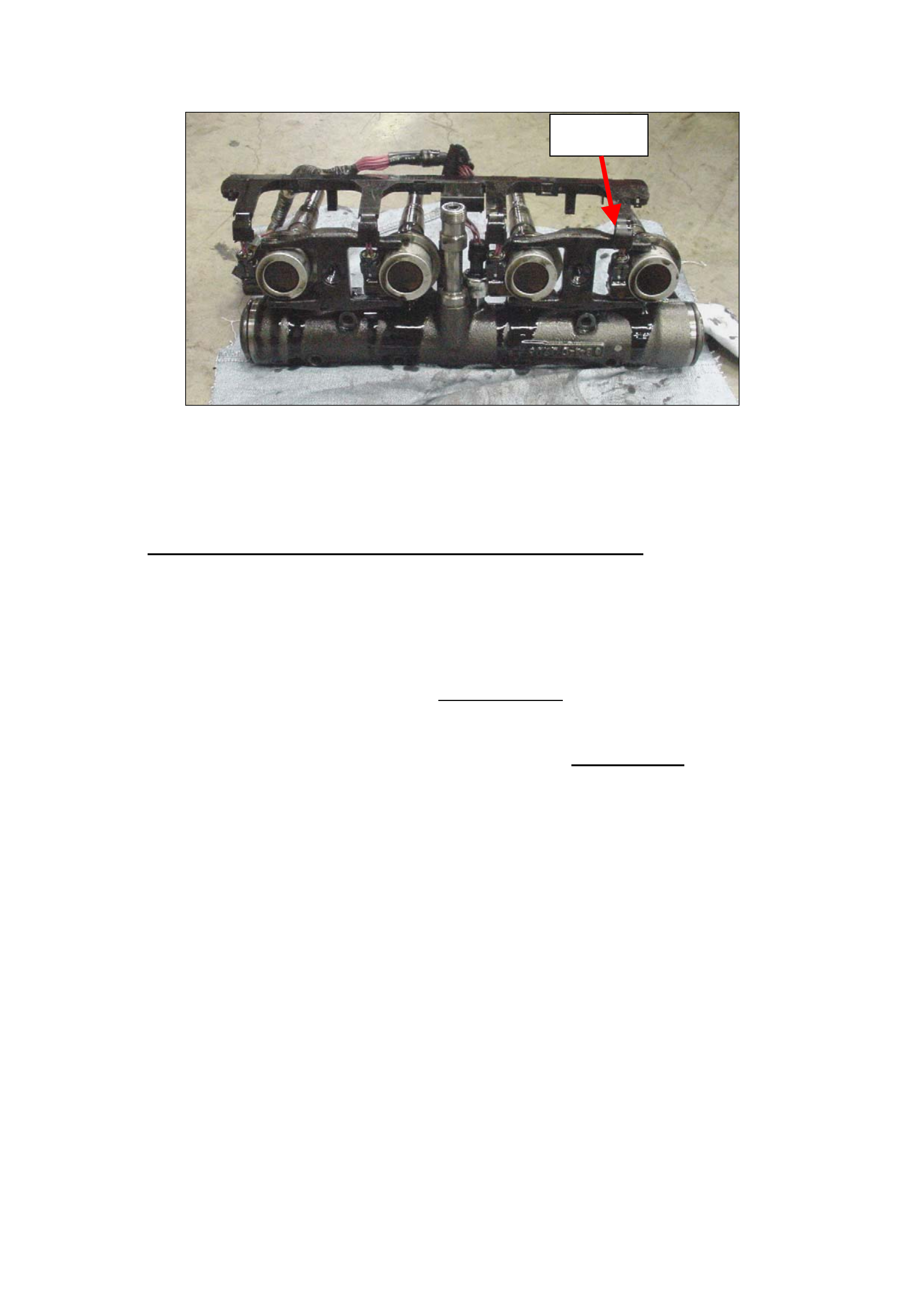
H-Clamp
Figure 3
NOTE: Be careful not to damage the injectors when removing and reinstalling
the assembly. Have a second person assist if required.
When access is not required cover exposed combustion chambers with a rag.
Section 3: Replace Injector Sleeves and Injector Seals
NOTE: The injectors must not be swapped between cylinder positions. Since the
engine is calibrated to match the specific injectors.
17. Clean and inspect the injectors. Wipe away soot and deposits from the tip of
the nozzle with solvent and a rag.
18. Remove and discard the injector Back Up O Ring and Sleeve rework if fitted as
previously advised in IGM 04/00.
CAUTION: The use of a brush with metal bristles may damage the
injector nozzle
19. Remove the injector to oil rail mounting bolts and move the injector to access
the seal.
NOTE: There is no need disconnect the injector harness from the injector. This
will avoid the potential to break Harness connector clips.
20. Replace all injector O-rings and gaskets indicated in figure 4 on all injectors.
Lubricate only the rubber seals with engine oil.
Page 9 of 21
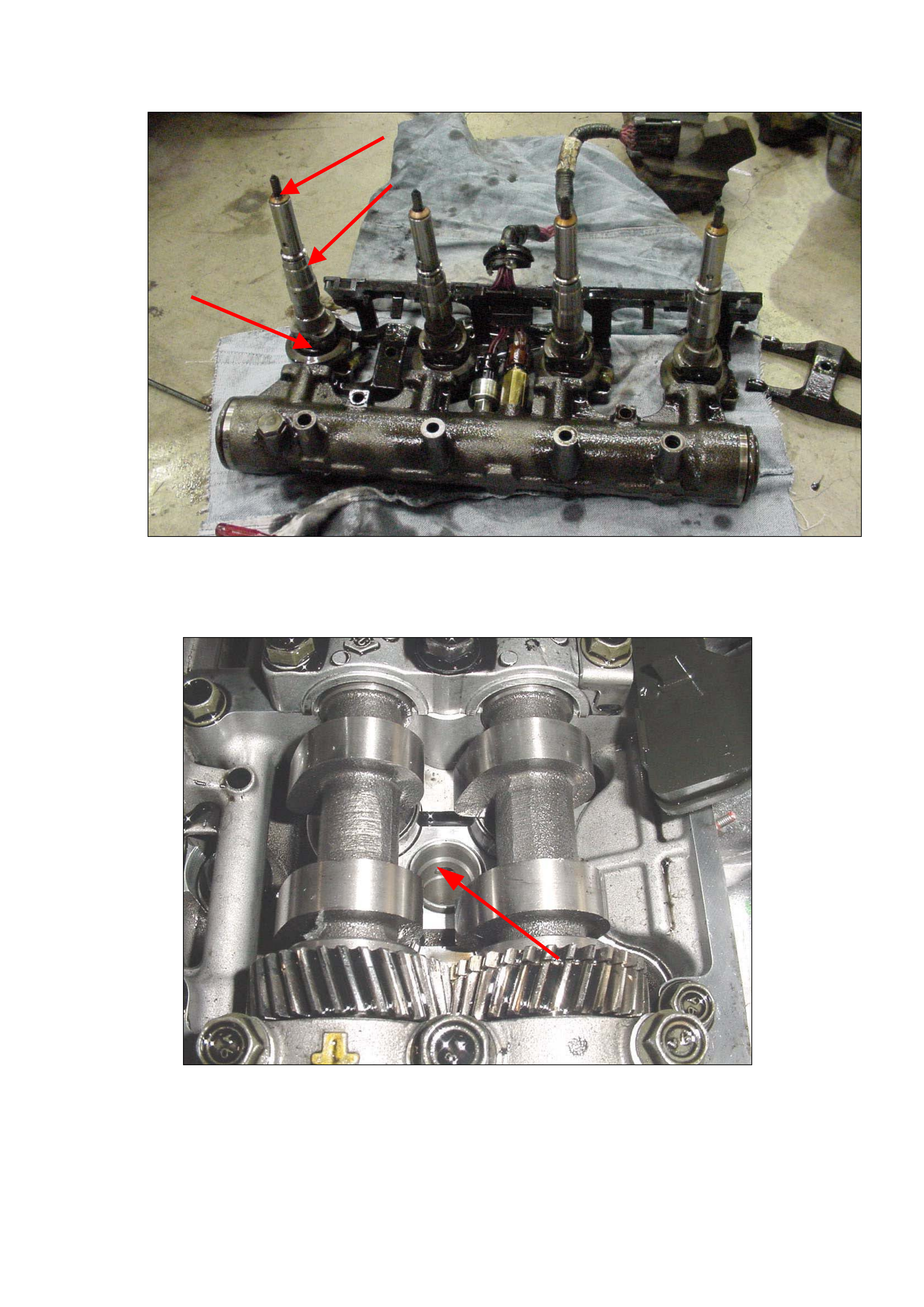
Figure 4 – Replace Injector Seals and Gaskets
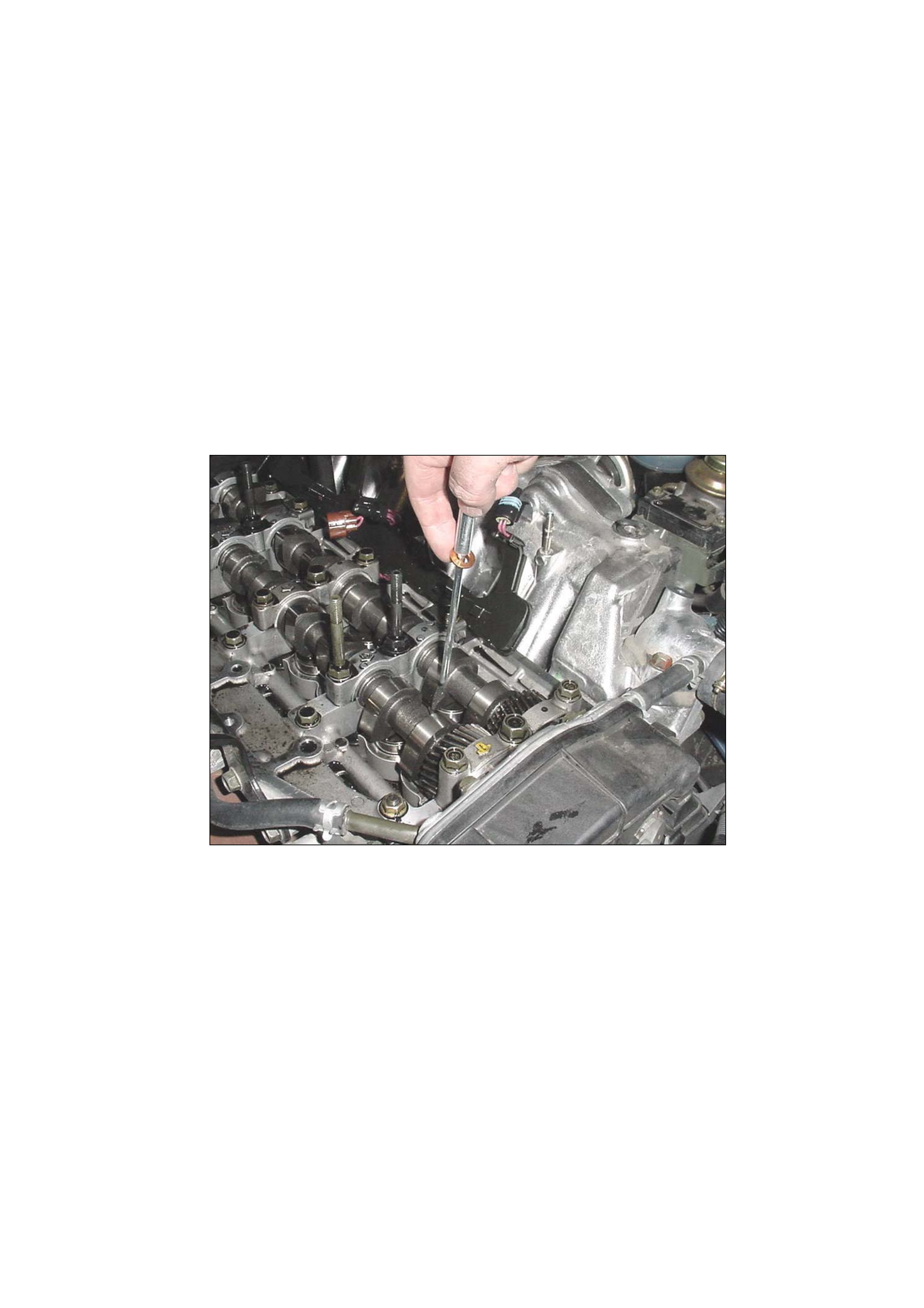
21. Inspect the injector sleeves in the cylinder head to locate the fuel gallery holes.
Refer Figure 5.
Figure 5 – Injector Sleeve Fuel Gallery Holes
22. Orient the sleeve removal tool so the teeth will engage the fuel gallery holes
when pushed into the sleeve. Refer Figure 6.
Page 10 of 21
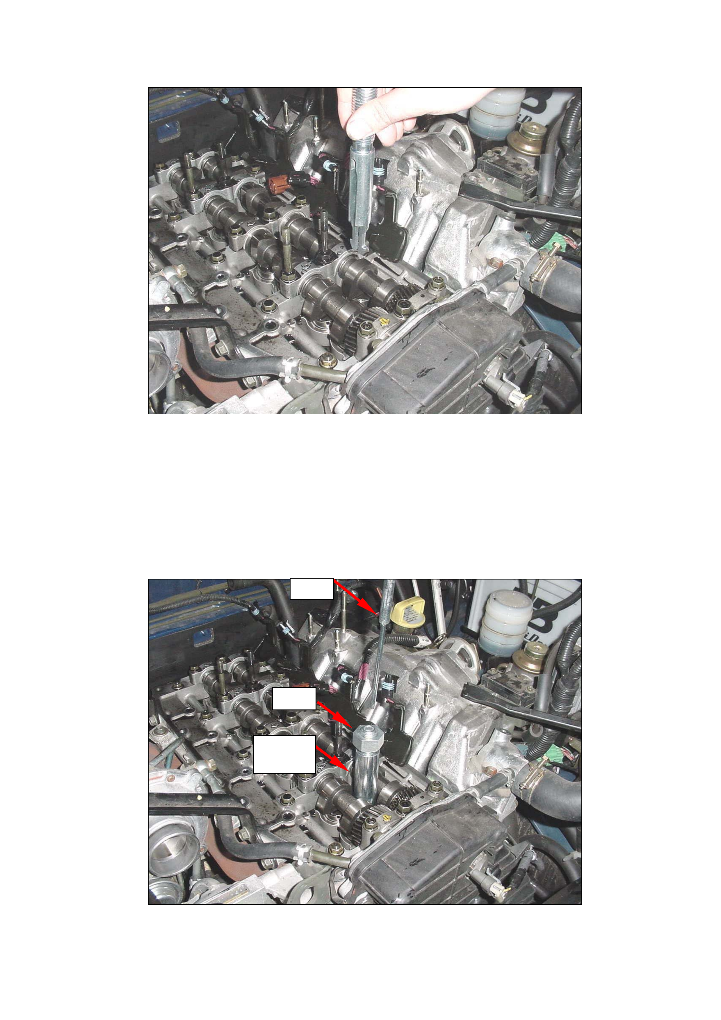
Figure 6 – Orienting Sleeve Removal Tool
23. Push the sleeve removal tool into the sleeve until the teeth on the tool engage
the fuel gallery holes. Twist the tool to check it is fully engaged.
24. Install the pin fully into the centre of the sleeve removal tool. If the pin does
not effortlessly seat or becomes jammed, the sleeve removal tool is not correctly
engaged in the injector sleeve and the removal tool will be damaged upon removal
(Fig 7 and 8).
25. Install the tool outer sleeve and nut.
Pin
Nut
Tool
Sleeve
Figure 7 – Sleeve Removal Tool Installed
Page 11 of 21
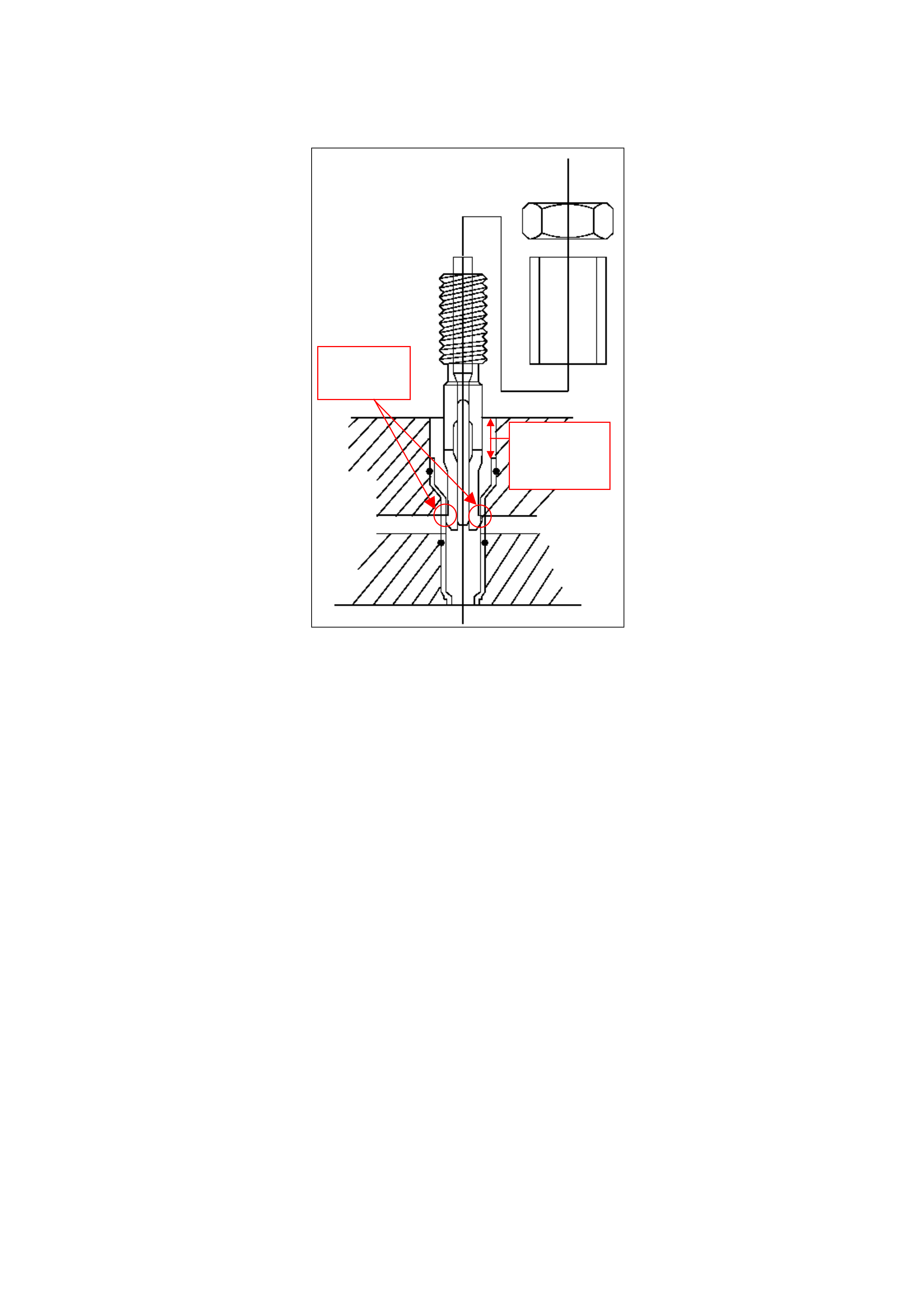
15mm –
refer step
Prongs
Engaged
19
Figure 8 – Tool Assembly in Cylinder Head
26. Hold the flat of the threaded section of the tool with a wrench and turn the nut
clockwise to remove the sleeve from the head. Refer Figure 9.
Page 12 of 21
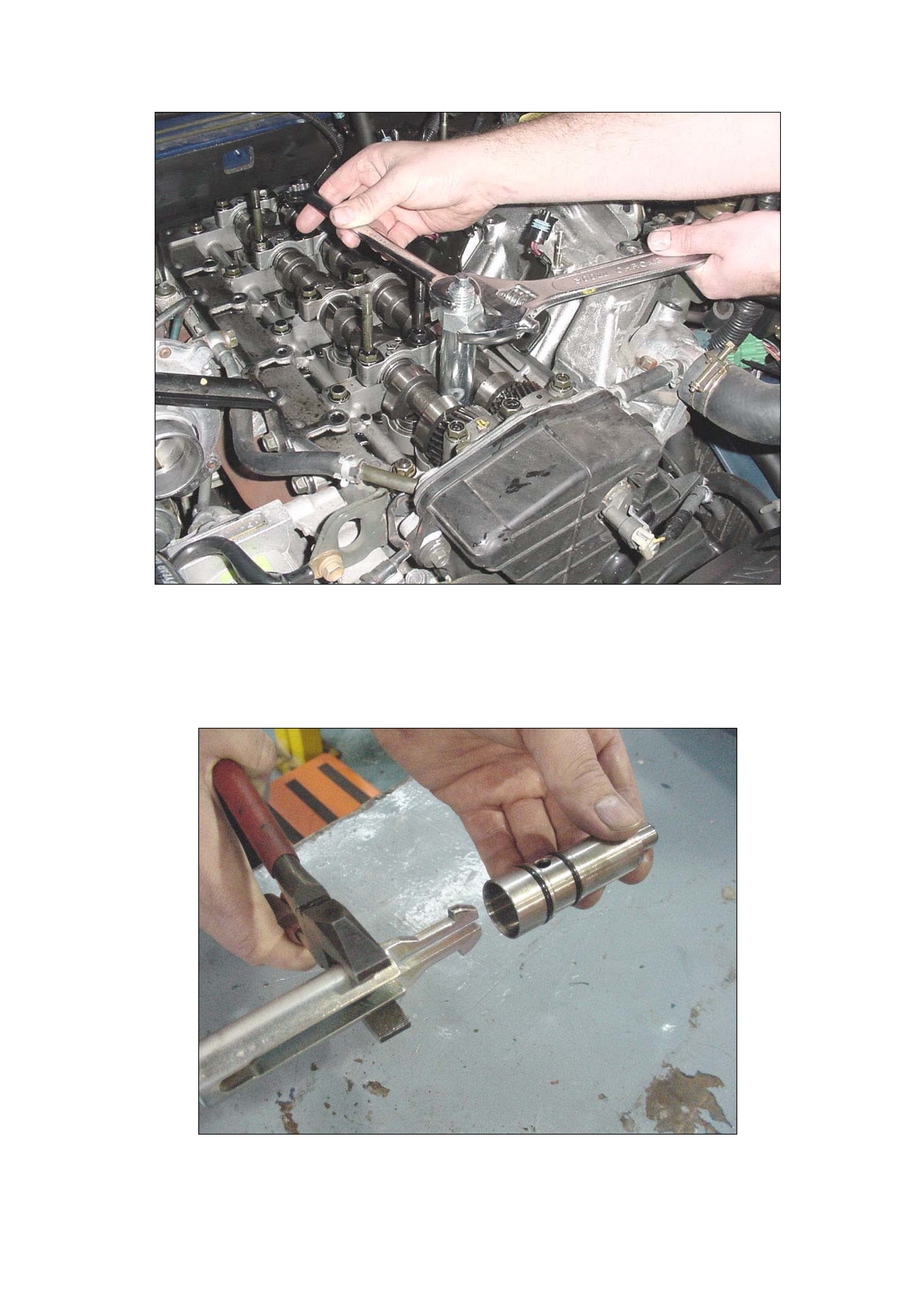
Figure 9 – Extracting the sleeve using the tool
27. Remove the pin from the tool. Using large pliers to compress the body of the
tool, release the teeth from the injector sleeve and remove (Fig 10).
NOTE: Do not compress the narrow teeth as damage to the tool may result.
Figure 10 – Removing the tool from the injector sleeve
Page 13 of 21
28. Repeat this process for the three remaining injector sleeves in the cylinder
head.
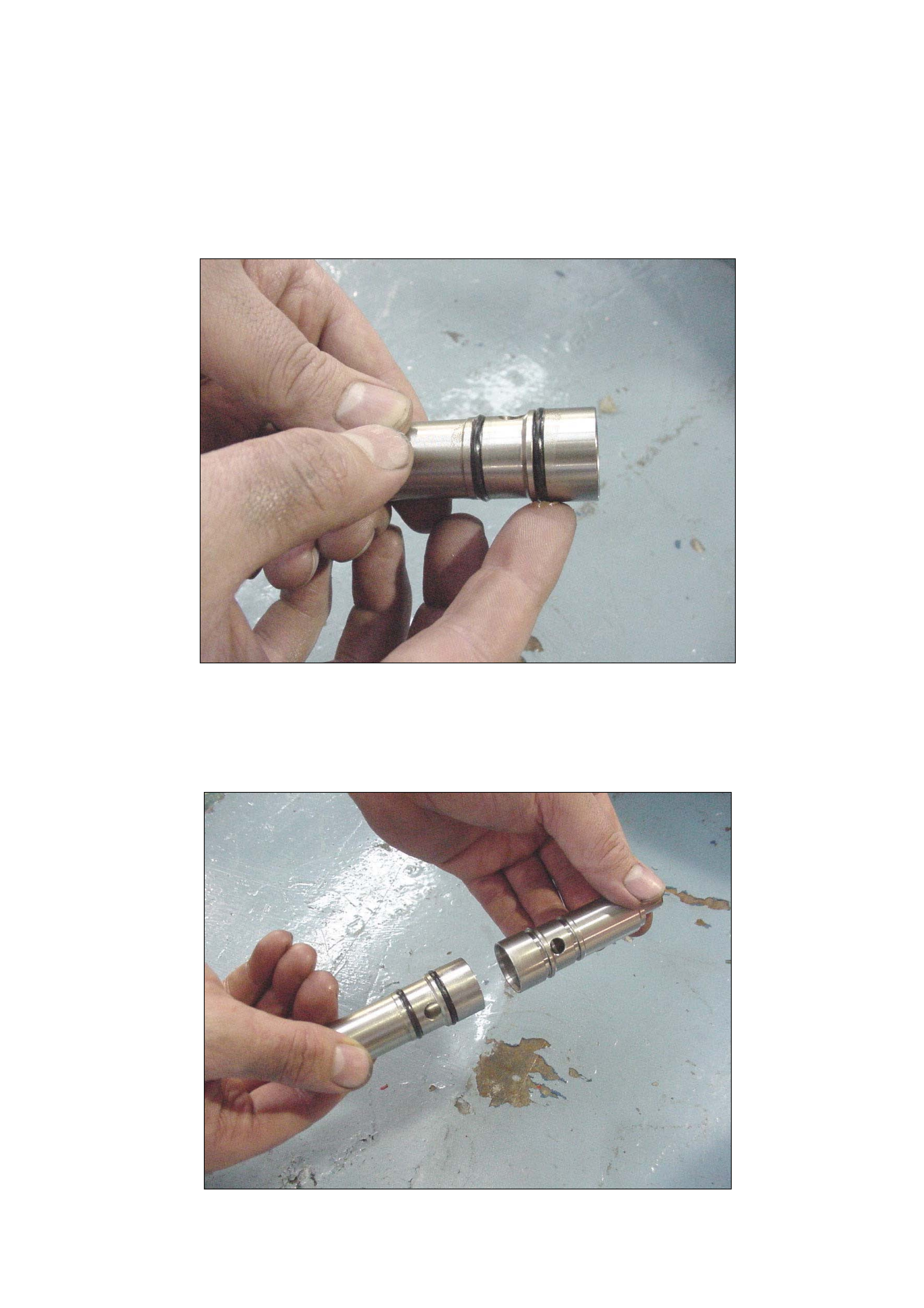
29. Clean the injector sleeve bores with a lint-free rag wrapped around a soft
material such as wood.
30. Prepare the new injector sleeves for installation by applying engine oil to the
O-rings (Fig. 11).
Figure 11 – Lubricate new injector sleeve O-rings
31. Thoroughly clean an old injector sleeve to use as an installer. Remove the O-
rings in order to easily identify.
32. The old sleeve will be used, upside down, to install the new sleeve (Fig. 11).
Page 14 of 21
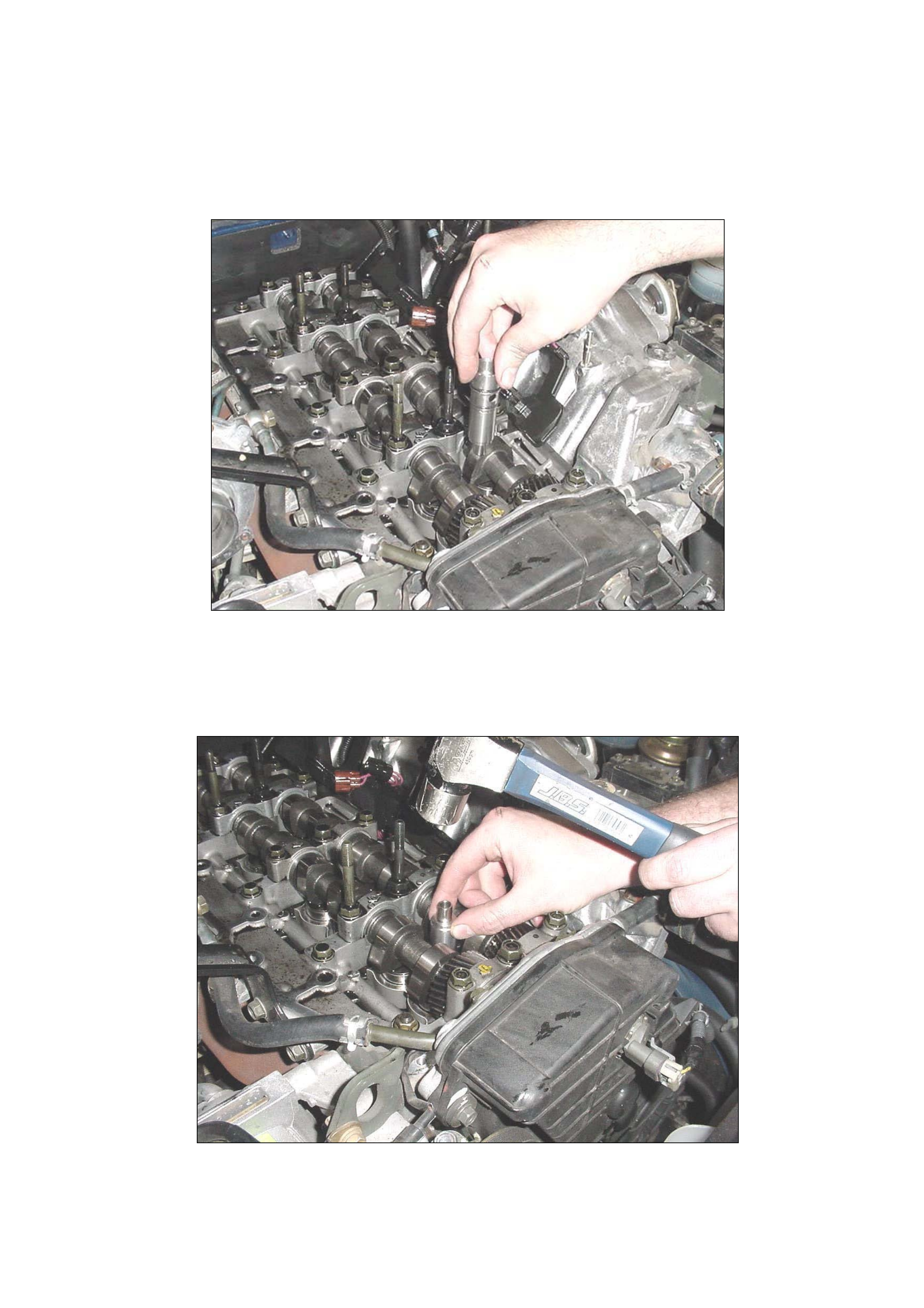
Figure 12 – Using old sleeve as installing tool
33. Place the new injector sleeve in the cylinder head. Align the fuel gallery holes
in the sleeve with the ports in the cylinder head (Fig 13).
Figure 13– Locating injector sleeves
34. Locate the clean, used injector sleeve upside down on the new sleeve.
35. Carefully install the new injector sleeve, using a hammer, until it is fully seated
in the cylinder head (Fig 14).
Figure 14 – Installing new injector sleeve
Page 15 of 21
NOTE: If unsure, check the injector sleeve is fully seated in the cylinder head by
measuring the depth of the sleeve in the head. The correct depth of the sleeve in
the cylinder head is 15mm (refer Figure 8). Once the sleeve is in the home
position do not continue to install the sleeve as damage may occur.
36. Repeat this procedure for the remaining three cylinder positions
37. Remove any oil or coolant that pooled in the combustion chamber with a
vacuum bleeder or syringe.
38. Insert the copper nozzle gasket into the injector sleeves taking care to ensure
the flat side faces up. Use the removal tool pin to guide the gasket into the sleeve.
Refer Figures 15 and 16.
NOTE: The surfaces of the copper gasket creates a seal and must be
clean (no visible sign of carbon, oil etc).
Do not use grease to hold the nozzle gasket on the injector during
insulation as a leak may develop.
Figure 15 – Installing the copper packing
39. Inspect the copper nozzle gasket packing in the sleeve to ensure it is installed
correctly with the flat side up ( See Fig 16).
Page 16 of 21
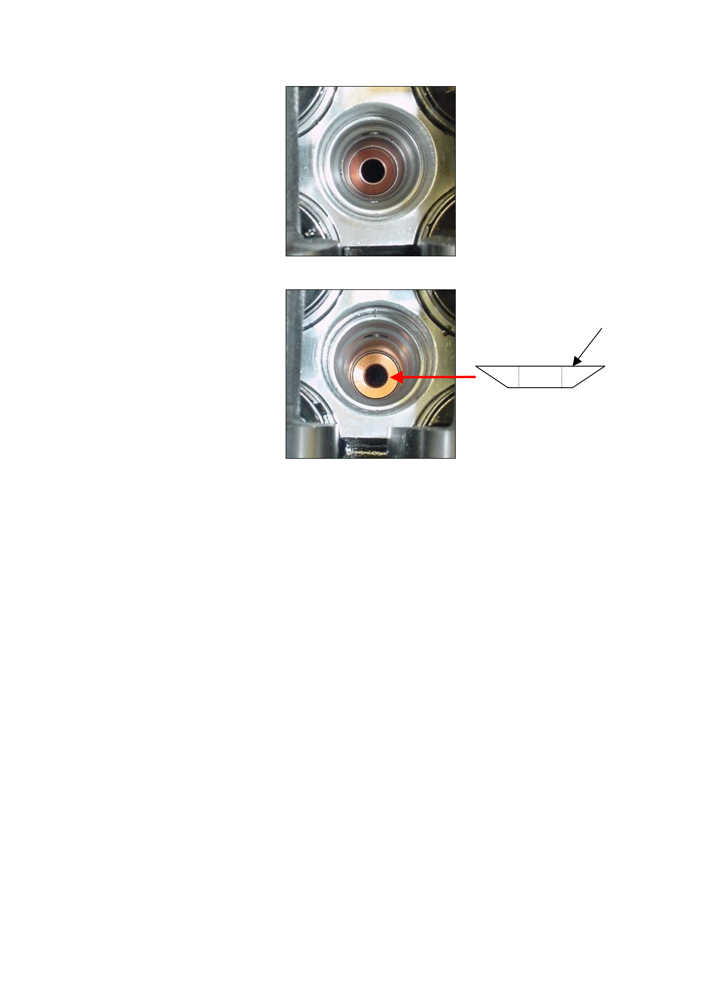
Incorrect (upside down)
Install flat Side up
Side view of
Copper gasket
Correct
Figure 16 – Copper Gasket Inspection
40. With the H-Clamps in place, install the oil rail, injectors and injector harness
assembly.
Note: Carefully install the injectors into the sleeves. Have a second person assist
if required. Take care not to bump the injector tips since they are brittle and
could be easily damaged if accidentally knocked.
Check the oil rail drain plug is installed.
41. Install and temporarily tighten the injector to rail bolts then injector clamp
bolts.
42. Install oil rail nuts and bolts but do not torque to specification until step 46.
NOTE: Clear any drained oil from around the injector to prevent oil running
into the combustion chamber.
43. Tighten injector to oil rail bolts to the specified torque.
Torque: 6.5 Nm (0.7 kgm / 5.1 Ib ft)
44. Tighten injector H-clamp nuts to the specified torque to seat the injectors:
Torque: 30 Nm (3.1 kgm / 22 Ib ft)
45. Loosen the injector H-clamp nuts and retighten to the specified torque:
Torque: 25 Nm (2.4 kgm / 17.4 Ib ft)
46. Torque the oil rail bolts to the specified torque:
Page 17 of 21

Torque: 20 Nm (2.0 kgm / 14.5 Ib ft)
47. Reinstall the remaining components in the reverse order (steps 15 – 1) while
noting the following points:
Ensure the wiring harness at the front of the cylinder head cover is not
damaged or caught during reassembly.
Tighten the cylinder head cover bolts to specific torque 9 Nm (0.9kgm/5.8 Ib
ft)
Fit new seals to the high pressure oil pipe and tighten to specific torque 80Nm
(8.1kg.m / 57.9 Ib ft)
When installing the cylinder head cover apply liquid gasket to the mating
corners of the front cam shaft bracket, seals for the injector harness in the
head and the seal at the rear of the head
Tighten intercooler mounting bolts to specific torque 20 Nm (2.0 kg.m /
14.5Ib ft)
Refill Coolant
Engine will take approx. 15 – 20 second of cranking to start.
48. Apply a recall campaign sticker and mark position C2 on the Vehicle Service
History Label.
49. Enter radio PIN and ensure correct operation.
Page 18 of 21

Page 19 of 21
APPENDIX C – Excluded Vehicle Listing : DO NOT REWORK
This is a list of EXCLUDED vehicles due to previous rework. This list is sorted into
Model Year categories. If the vehicle is shown on the list below in the applicable
Model Year category it does not require campaign action.
1998 Model Year 1998 Model Year cont’d 1999 Model Year cont’d
JACUBS73GW7100023 JACUBS73GW7102384 JACUBS73GX7101549
JACUBS73GW7100222 JACUBS73GW7102410 JACUBS73GX7101573
JACUBS73GW7100247 JACUBS73GW7102471 JACUBS73GX7101575
JACUBS73GW7100293 JACUBS73GW7102575 JACUBS73GX7101576
JACUBS73GW7100331 JACUBS73GW7102577 JACUBS73GX7101595
JACUBS73GW7100381 JACUBS73GW7102640 JACUBS73GX7101621
JACUBS73GW7100496 JACUBS73GW7102687 JACUBS73GX7101634
JACUBS73GW7100546 JACUBS73GW7102713 JACUBS73GX7101704
JACUBS73GW7100842 JACUBS73GW7102776 JACUBS73GX7101777
JACUBS73GW7100985 JACUBS73GW7102868 JACUBS73GX7101800
JACUBS73GW7101101 JACUBS73GW7102951 JACUBS73GX7101842
JACUBS73GW7101105 JACUBS73GW7102979 JACUBS73GX7101904
JACUBS73GW7101248 JACUBS73GW7103093 JACUBS73GX7101954
JACUBS73GW7101267 JACUBS73GW7103198 JACUBS73GX7102004
JACUBS73GW7101291 JACUBS73GW7103217 JACUBS73GX7102027
JACUBS73GW7101309 JACUBS73GW7103218 JACUBS73GX7102043
JACUBS73GW7101313 JACUBS73GW7103350 JACUBS73GX7102050
JACUBS73GW7101367 JACUBS73GW7103374 JACUBS73GX7102062
JACUBS73GW7101373 JACUBS73GW7103391 JACUBS73GX7102102
JACUBS73GW7101396 JACUBS73GW7103423 JACUBS73GX7102152
JACUBS73GW7101416 JACUBS73GW7103438 JACUBS73GX7102207
JACUBS73GW7101417 JACUBS73GW7103461 JACUBS73GX7102226
JACUBS73GW7101428 JACUBS73GX7102233
JACUBS73GW7101504 JACUBS73GX7102269
JACUBS73GW7101513 1999 Model Year JACUBS73GX7102331
JACUBS73GW7101515 JACUBS73GX7100620 JACUBS73GX7102452
JACUBS73GW7101528 JACUBS73GX7100690 JACUBS73GX7102496
JACUBS73GW7101532 JACUBS73GX7100814 JACUBS73GX7102554
JACUBS73GW7101537 JACUBS73GX7100875 JACUBS73GX7102645
JACUBS73GW7101540 JACUBS73GX7100927 JACUBS73GX7102760
JACUBS73GW7101543 JACUBS73GX7100930 JACUBS73GX7102761
JACUBS73GW7101584 JACUBS73GX7100984 JACUBS73GX7102766
JACUBS73GW7101595 JACUBS73GX7101002 JACUBS73GX7103262
JACUBS73GW7101600 JACUBS73GX7101097 JACUBS73GX7103266
JACUBS73GW7101607 JACUBS73GX7101206 JACUBS73GX7103398
JACUBS73GW7101608 JACUBS73GX7101269 JACUBS73GX7103400
JACUBS73GW7101787 JACUBS73GX7101280 JACUBS73GX7103402
JACUBS73GW7101816 JACUBS73GX7101410 JACUBS73GX7103427
JACUBS73GW7101987 JACUBS73GX7101449 JACUBS73GX7103513
JACUBS73GW7102008 JACUBS73GX7101544 JACUBS73GX7103555
JACUBS73GW7102047 JACUBS73GX7101545 JACUBS73GX7103635
JACUBS73GW7102100 JACUBS73GX7101547 JACUBS73GX7103719
JACUBS73GW7102311 JACUBS73GX7103736
Continued over page

Page 20 of 21
Continued from previous page
1999 Model Year cont’d 1999 Model Year cont’d 2000 Model Year cont’d
JACUBS73GX7103898 JACUBS73GX7104750 JACUBS73GY7100998
JACUBS73GX7103909 JACUBS73GX7104765 JACUBS73GY7101000
JACUBS73GX7103953 JACUBS73GX7104774 JACUBS73GY7101002
JACUBS73GX7103963 JACUBS73GX7104777 JACUBS73GY7101009
JACUBS73GX7103982 JACUBS73GX7104779 JACUBS73GY7101022
JACUBS73GX7103984 JACUBS73GX7104780 JACUBS73GY7101038
JACUBS73GX7104005 JACUBS73GX7104781 JACUBS73GY7101060
JACUBS73GX7104076 JACUBS73GX7104786 JACUBS73GY7101070
JACUBS73GX7104078 JACUBS73GX7104800 JACUBS73GY7101071
JACUBS73GX7104128 JACUBS73GX7104812 JACUBS73GY7101083
JACUBS73GX7104147 JACUBS73GX7104813 JACUBS73GY7101092
JACUBS73GX7104174 JACUBS73GX7104820 JACUBS73GY7101127
JACUBS73GX7104218 JACUBS73GX7104822 JACUBS73GY7101140
JACUBS73GX7104259 JACUBS73GX7104827 JACUBS73GY7101180
JACUBS73GX7104288 JACUBS73GX7104836 JACUBS73GY7101181
JACUBS73GX7104322 JACUBS73GX7104839 JACUBS73GY7101226
JACUBS73GX7104382 JACUBS73GX7104844 JACUBS73GY7101233
JACUBS73GX7104399 JACUBS73GX7104845 JACUBS73GY7101287
JACUBS73GX7104400 JACUBS73GX7104852 JACUBS73GY7101290
JACUBS73GX7104419 JACUBS73GX7104854 JACUBS73GY7101294
JACUBS73GX7104436 JACUBS73GX7104860 JACUBS73GY7101299
JACUBS73GX7104450 JACUBS73GX7104861 JACUBS73GY7101362
JACUBS73GX7104464 JACUBS73GX7104863 JACUBS73GY7101376
JACUBS73GX7104480 JACUBS73GX7104864 JACUBS73GY7101384
JACUBS73GX7104481 JACUBS73GX7104872 JACUBS73GY7101389
JACUBS73GX7104483 2000 Model Year JACUBS73GY7101456
JACUBS73GX7104503 JACUBS73GY7100013 JACUBS73GY7101498
JACUBS73GX7104505 JACUBS73GY7100016 JACUBS73GY7101510
JACUBS73GX7104506 JACUBS73GY7100140 JACUBS73GY7101513
JACUBS73GX7104520 JACUBS73GY7100176 JACUBS73GY7101543
JACUBS73GX7104522 JACUBS73GY7100197 JACUBS73GY7101596
JACUBS73GX7104527 JACUBS73GY7100319 JACUBS73GY7101608
JACUBS73GX7104548 JACUBS73GY7100340 JACUBS73GY7101609
JACUBS73GX7104565 JACUBS73GY7100403 JACUBS73GY7101611
JACUBS73GX7104567 JACUBS73GY7100437 JACUBS73GY7101648
JACUBS73GX7104570 JACUBS73GY7100630 JACUBS73GY7101714
JACUBS73GX7104571 JACUBS73GY7100739 JACUBS73GY7101752
JACUBS73GX7104594 JACUBS73GY7100807 JACUBS73GY7101825
JACUBS73GX7104609 JACUBS73GY7100810 JACUBS73GY7101858
JACUBS73GX7104627 JACUBS73GY7100816 JACUBS73GY7101880
JACUBS73GX7104632 JACUBS73GY7100861 JACUBS73GY7101895
JACUBS73GX7104649 JACUBS73GY7100864 JACUBS73GY7101973
JACUBS73GX7104670 JACUBS73GY7100867 JACUBS73GY7101985
JACUBS73GX7104698 JACUBS73GY7100888
JACUBS73GX7104699 JACUBS73GY7100890
JACUBS73GX7104700 JACUBS73GY7100895
JACUBS73GX7104719 JACUBS73GY7100901
JACUBS73GX7104724 JACUBS73GY7100902
JACUBS73GX7104742 JACUBS73GY7100987
JACUBS73GX7104744 JACUBS73GY7100996
JACUBS73GY7100997
Appendix D – SALMAT MATERIAL ORDER FORM
Confirmation of parts order received by Salmat on:
Injector Seal Recall 03-H-03
Fax this form to SALMAT ON: (03) 9358 – 2999
IMPORTANT:
Only order parts after securing a vehicle booking.
The vehicle ISOVIN to be reworked must be specified below.
PART NUMBER APPLICATION
QTY
03-H-03 Injector Sleeve Recall Kit
VEHICLE ISOVIN
Contact Name: _______________________________________________
Retailer Code: _______________________ Date: ________________
Retailer Name: ______________________ Ph. No: ______________
Retailer Address: _______________________________________________
Fax No.: _______________________________________________
SALMAT USE ONLY
Retailer Order Acknowledgement faxed back to retailer within 24 hours of receiving YES / NO
QUANTITY REQUESTED DESPATCHED YES / NO (PLEASE CIRCLE APPROPRIATE
RESPONSE)
Date dispatched
FREIGHT FORWARD AGENT
Consignment Note Number
Page 21 of 21

PRODUCT CAMPAIGN BULLETIN
03-H-04
December 15th, 2003
SUBJECT: DRIVER’S SEAT WIRING HARNESS ROUTING
MODELS AFFECTED: V2 SERIES 3 - MONARO CV8 AND HSV COUPE.
This bulletin announces the initiation of SAFETY RELATED recall campaign 03-
H-04 which consists of a small batch of V2 series 3 Monaro and V2 series 3
HSV Coupe.
This bulletin incorporates the inspection of driver’s seat memory module wiring
to side outer cover for damage and to install a positive location retention clip.
Only 87 V2 series 3 Monaro CV8 models and V2 series 3 HSV Coupe models
are affected by the recall action.
DESCRIPTION OF DEFECT
Some driver’s seats fitted to V2 series 3 vehicles (attached list Appendix C),
may have been manufactured with an incorrectly routed seat memory module
wiring harness or the wiring harness not positively secured.
The wiring harness affected, is routed between the upper and lower sections of
the driver’s seat track and frame assembly. When the seat is moved to the fully
down position, this harness (if incorrectly positioned), may be damaged causing
an electrical fault, which can cause the driver’s seat to move unintentionally.
AFFECTED VEHICLES
A list of all affected V2 Series 3 Monaro CV8 and V2 series 3 HSV Coupe
models is attached to this bulletin (Appendix C).
ACTION REQUIRED BY RETAILERS
1. Review the Affected Vehicle Listing (Appendix C).
2. Check for affected models in Retailer stock and if listed on Appendix C
rectify before delivery or transfer. Please quarantine any stock vehicle/s
until the rectification is completed.
3. Check all V2 Series 3 Monaro CV8 and V2 series 3 HSV Coupe vehicle
ISOVIN’s against the affected vehicle list (Appendix C), when vehicles are
presented at Retailerships for any reason.
4. If the vehicle on the list of affected vehicles and has not been previously
campaigned (identified by a Campaign 03-H-04 Completed Label on the
RHS ‘A’Pillar), then the vehicle requires this Recall Campaign action.
5. Proceed with campaign action as detailed in the Campaign Technical
Instructions attached.
6. Apply a Campaign Completed Label and a Vehicle Service History Label as
specified in the section titled ‘Campaign Completion Identification’.
7. Submit a warranty claim. Refer Warranty Claim Information below.
Page 1 of 10

CUSTOMER NOTIFICATION
Owners of vehicles affected by this recall campaign will be contacted directly by
a letter from Holden. Mailing of these letters will commence in early January
2004.
The letter provides details of the recall and requests the customer to contact
their Holden Retailer to make a booking to have the appropriate work carried
out. Refer to Appendix A for an example of the draft Customer Letter.
CAMPAIGN COMPLETION IDENTIFICATION
All campaigned vehicles must have:
1. A Campaign Completed label applied to the right hand front ‘A’ pillar,
between the hinges, with details of the campaign:-
• Campaign No. “03-H-04”
• Retailer Code
• Date legibly entered on the label with a permanent ink pen.
AND
2. For additional identification, mark an “X” at the A4 –coordinate of a vehicle
Service History Label and apply to the inner side of the lower instrument
panel cover.
Extra Campaign Completed and Vehicle Service History labels are available free
of charge from Moore Business Systems.
• For Campaign Completed Labels Quote stock no. SD 28156 on a Moore
Business Systems ‘Packaged Goods’ order form for a pack of 100 labels.
• For Vehicle Service History Labels quote stock no. SD 28177 on a Moore
Business Systems ‘Packaged Goods’ order form for a pack of 100 labels.
Fax the order form to Moore Business Systems on Facsimile: (03) 9270 8925
Should you need to follow-up on a placed order, contact Moore customer
service on telephone number (03) 9270 8788.
Page 2 of 10

Page 3 of 10
PARTS INFORMATION
Two clips have been allocated to each retailer for vehicles presented for
campaign action. Additional clips are available free of charge from Salmat by
completing and faxing the Material Order Form. (Refer to Appendix D).
PART
NUMBER
DESCRIPTION QUANTITY
92147519 03-H-04 Campaign Part (Clip) 1
In the rare instance where inspection of the wiring harness reveals damage (as
defined in the Technical Instructions - Appendix B) and seat harness
replacement is required, a nominated contact should contact TAS (Holden
Technical Assistance Service) on 1800 033 417.
WARRANTY CLAIM INFORMATION
On completion of campaign action, retailers are requested to IMMEDIATELY
submit a warranty claim using the applicable Recall Campaign Labour Operation
Number specified below. Only claim one of the two Labour Operation Numbers
shown below:
Warranty Claim Information for V2 Series 3 Vehicles
Description: Inspect seat wiring for
retaining clip
Inspect seat wiring and
install retainer clip
(if not fitted)
Labour Operation No
Standard Time:
Failure Code:
Case Type
T380403
0.5 Hrs
96 - T0096
08
T380404
0.6 Hrs
96
08
CONTACT INFORMATION
For further information or clarification on this recall campaign please contact the
relevant person below.
CONTACT NAME CONTACT NUMBER
General enquiries Brett Fowler (03) 9647 1857
Technical enquiries TAS 1800 033 417
Parts related enquiries Salmat (03) 9358 2990
Warranty related inquiries Warranty Administration (03) 9647 2401
Attachments
Appendix A Customer Letter- Draft for V2 series 3
Appendix B Campaign Technical Instructions for V2 Series 3
Appendix C Affected Vehicle Listing
Appendix D Material Order Form V2 series 3

Page 4 of 10
APPENDIX A - Draft – Customer Letter
VEHICLE SAFETY RECALL
03-H-04
Re: Monaro Series III and HSV Coupe Series III
Driver’s Seat Wiring Harness
Dear Holden Customer,
As part of Holden’s ongoing commitment to customer satisfaction and safety, we
have initiated a safety-related recall on a limited range of Holden Series III CV8
Monaro and HSV Series III Coupe model vehicles.
A wiring harness retaining clip may not have been installed to some
driver’s seats fitted to these vehicles. Without this retaining clip, wiring
harness damage may potentially occur when the driver’s seat is adjusted
to the lowest position.
This damage may result in an electrical fault that can cause the driver’s seat to
move unexpectedly in the forwards or backwards direction to the limits of seat
adjustment and this may affect driver’s control of the vehicle.
Holden has initiated this campaign to enable us to check for correct harness
retention, so that the potential for this damage is eliminated.
Our records show that your vehicle was manufactured within the affected range.
It is therefore necessary for you to contact a Holden Retailer of your choice and
make a booking as soon as possible to have your vehicle inspected and reworked
if the retaining clip is not fitted. The work required will be carried out free of
charge.
Until this rework is completed on your vehicle, Holden recommends that the
driver’s seat height adjustment is NOT set to the fully “down” position.
If you have any questions regarding this recall, please contact your Holden
Retailer or call the Holden Recall Assistance Line – 1800 632 826 and we will be
pleased to assist you further.
Thank you for your attention to this matter. Please accept our apologies
for any inconvenience this causes to you.
Yours sincerely
David McMurray
Manager Customer Assistance
Page 5 of 10
APPENDIX B - Campaign Technical Instructions for V2 Series 3
Follow the steps below to install the harness retaining clip to the Driver’s
Side Seat Wiring Harness.
1. Confirm that campaign action has not already been performed by inspecting
for a 03-H-04 Campaign Completed label or Vehicle Service History label co-
ordinate, A-4.
2. Ensure Radio pin number is recorded prior to disconnecting vehicle battery.
3. Drive the seat fully forward (towards the steering wheel), using the electric
seat switches.
4. Adjust the seat to the highest upward position by operating the electric seat
switches.
5. Disconnect the battery to disable the SRS system before proceeding.
6. Remove the Drivers front seat side cover, refer to SIP CD section 1A7-4.3
(attached on page 8).
NOTE: Care must be taken not to damage the removable screw plastic plug.
Figure 1
7. Inspect for the installation of a harness retaining clip securing the harness to
the lower seat track – refer Fig 4. If no clip is present or the clip does not
secure the harness, then proceed to step 8. If a clip secures the harness
already, go to step 11.
Page 6 of 10
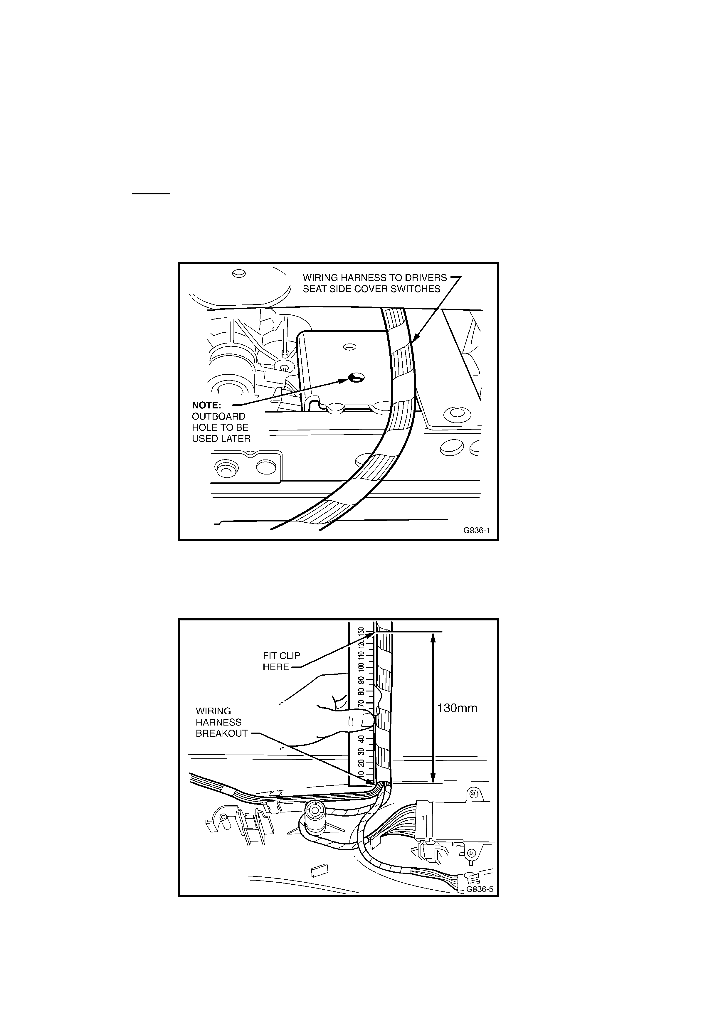
8. Locate the wiring harness as indicated in Figure2 below and inspect for
damage. Inspect for any harness damage where the harness passes over
seat rail.
• If only the wire insulation is damaged, repair by wrapping with
electrical insulation tape.
• If wire strands (copper conductors) are broken within any wires,
replace harness – refer TAS (Holden Technical Assistance Service).
Note: If the harness requires replacement, a TAS nominated contact
should call Holden’s Technical Assistance Centre on 1800 033 417 for
a replacement harness, harness routing instructions and a Labour
Operation number.
Figure 2
9. Measure 130 mm from the wiring harness breakout as indicated in Figure 3.
Attach the harness clip at the measured point to the wiring harness.
Figure 3
Page 7 of 10
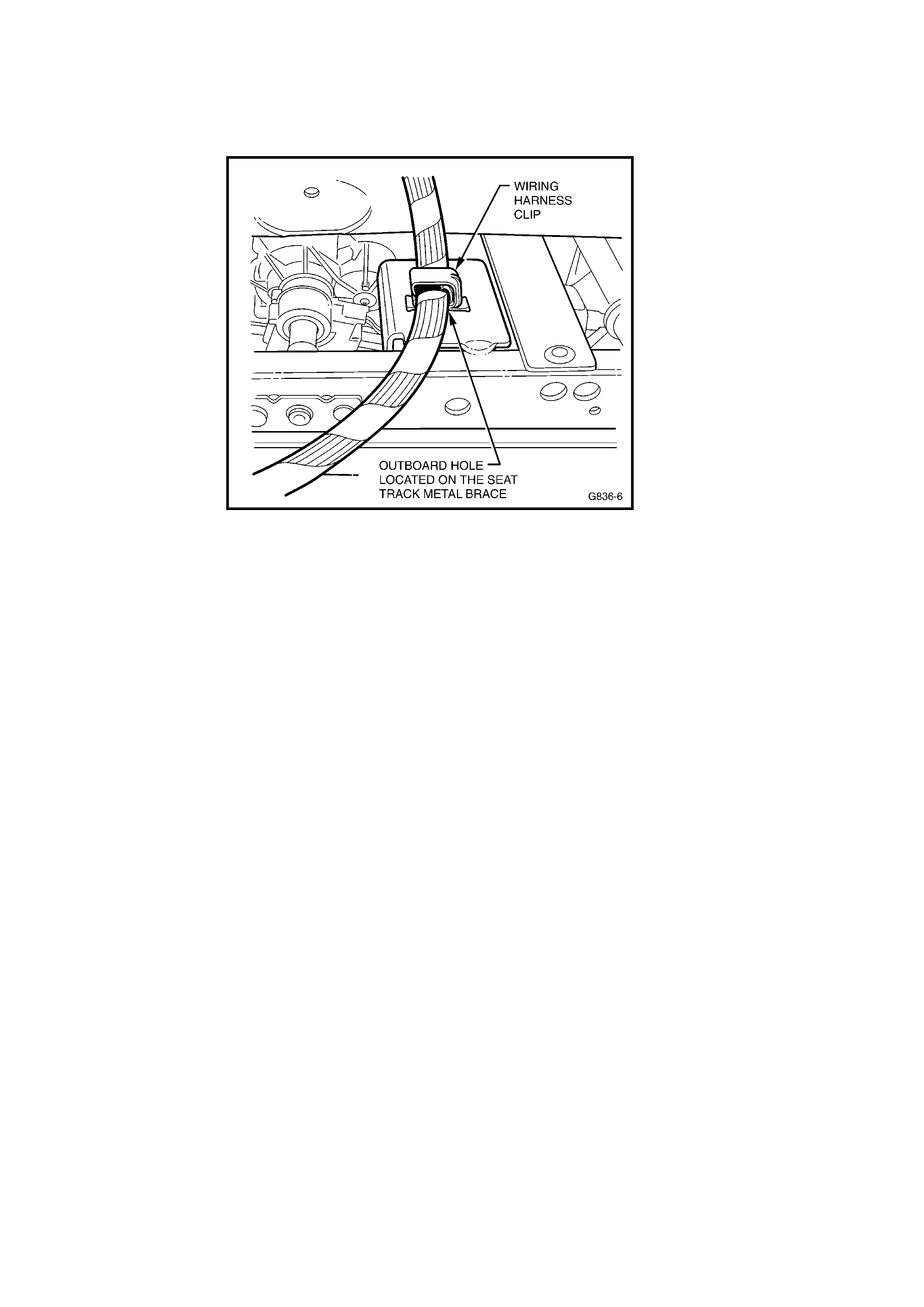
10. Insert the wiring harness clip into the “outboard” mounting hole(See Figure 2)
of the seat track brace with the clip opening facing towards the rear of the
vehicle as shown in Figure 4.
Figure 4
11. Refit the side seat outer cover. Refer to SIP CD section 1A7-4.3 on the
following page.
Caution: Care must be taken to avoid any damage to the plastic trims.
12. Reconnect battery to enable SRS system.
13. Check for correct operation of seat travel in all modes.
14. Ensure radio is operational.
15. Apply a campaign completed label and a vehicle Service History label as
specified in the Campaign Completed section of this Campaign Bulletin.
16. END OF PROCEDURE.
Page 8 of 10
Extract Of SIP Instructions
4.3 FRONT SEAT OUTER SIDE COVER
LT Section No. – 14-322
IMPORTANT: If the seat assembly is to be dissembled, adjust the seat assembly to its highest position before disconnecting
the power to the seat.
Remove
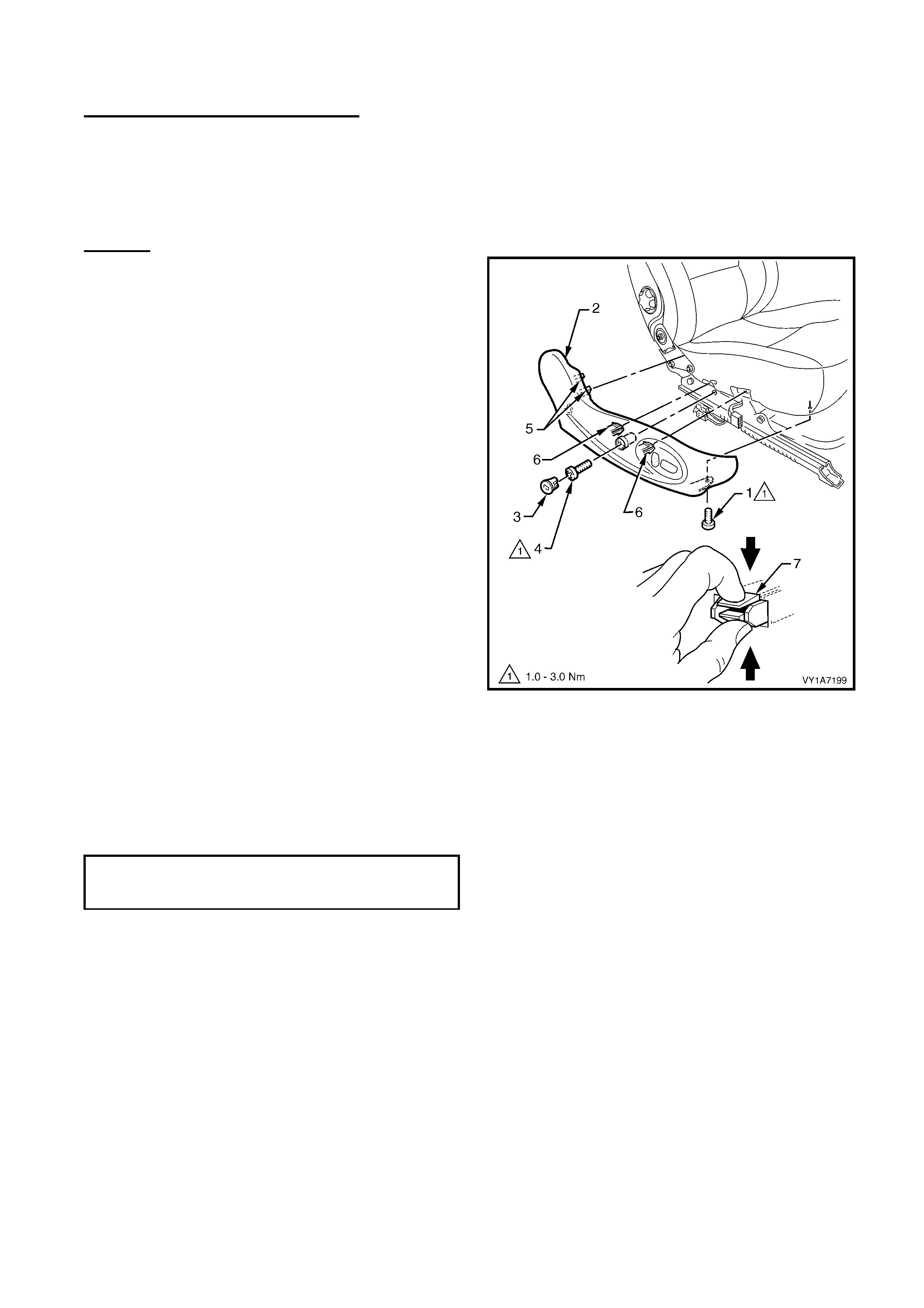
1. Remove the screw (1) from the front of the outer
side cover (2).
2. Remove the front seat outer side cover plug (3) by
rotating the plug anti-clockwise, one quarter of a
turn.
TIP: A fine screwdriver, would be useful to aid the
removal of the side cover plug without damage.
3. Remove the screw (4) located behind the plug.
4. Gently pull the outer cover away from the seat-
back recliner to disengage the two clips (5)
attached to the recliner frame.
5. Reach up under the seat assembly and squeeze
together the two retaining tangs (6), on the inner
side of the outer cover while gently pulling the
outer cover.
NOTE: Only remove the outer cover far enough away
from the seat cushion assembly to gain access to the
seat wiring harness connectors.
Figure 1A7-1
Install
Reinstallation of the front seat outer side cover is the reverse
of the removal procedure, noting the following:
1. Ensure all fasteners are tightened to the correct torque
specification.
FRONT OUTER SIDE COVER
ATTACHING SCREW
TORQUE SPECIFICATION 1.0 – 3.0 Nm

APPENDIX C – Affected Vehicle Listing
Complete list of Recall Campaign 03-H-04 affected V2 Series 3 vehicles
6G1VX14F94L144118
6G1VX14F24L144154
6G1VX14F04L144167
6G1VX14F84L144823
6G1VX14F04L144833
6G1VX14F34L144843
6G1VX14F64L167601
6G1VX14F24L167627
6G1VX14F14L167635
6G1VX14F14L168333
6G1VX14F24L168339
6G1VX14F34L168379
6G1VX14F94L169049
6G1VX14F64L169056
6G1VX14F44L169086
6G1VX14F34L169094
6G1VX14F54L169730
6G1VX14F74L169745
6G1VX14FX4L16976
9
6G1VX14F34L169774
6G1VX14F14L170423
6G1VX14FX4L17043
6
6G1VX14F14L170440
6G1VX14FX4L17045
3
6G1VX14F74L170457
6G1VX14F04L170462
6G1VX14F84L170466
6G1VX14F54L170487
6G1VX14F64L170496
6G1VX14F44L170500
6G1VX14F94L171108
6G1VX14FX4L17112
0
6G1VX14F44L171128
6G1VX14F94L171142
6G1VX14F44L171159
6G1VX14F64L171163
6G1VX14F54L171171
6G1VX14F54L171784
6G1VX14F24L171807
6G1VX14F64L171812
6G1VX14F74L171818
6G1VX14F44L171839
6G1VX14F34L171850
6G1VX14F44L171856
6G1VX14F54L171901
6G1VX14F54L172370
6G1VX14F34L172402
6G1VX14F64L172412
6G1VX14F44L172425
6G1VX14FX4L17242
8
6G1VX14F54L172434
6G1VX14F14L172446
6G1VX14F74L172452
6G1VX14F84L172458
6G1VX14F74L172466
6G1VX14F64L173074
6G1VX14F14L173080
6G1VX14F74L173097
6G1VX14F94L173103
6G1VX14F44L173106
6G1VX14F14L173127
6G1VX14F14L173130
6G1VX14F14L173144
6G1VX14F34L173159
6G1VX14F44L173817
6G1VX14FX4L17382
3
6G1VX14F24L173847
6G1VX14F54L173860
6G1VX14F04L173880
6G1VX14F14L173886
6G1VX14F94L173893
6G1VX14FX4L17451
8
6G1VX14F34L174540
6G1VX14F44L174546
6G1VX14F84L174565
6G1VX14F34L174568
6G1VX14F34L174571
6G1VX14F14L174584
6G1VX14F74L174590
6G1VX14F74L175299
6G1VX14F04L175340
6G1VX14F04L176018
6G1VX14F44L176040
6G1VX14F94L176048
6G1VX14F74L176081
6G1VX14F44L176085
6G1VX14F94L176633
Page 9 of 10

Page 10 of 10
APPENDIX D – SALMAT MATERIAL ORDER FORM
Confirmation of parts order received by Salmat on:
Seat Wiring Harness Securing 03-H-04
Fax this form to SALMAT ON: (03) 9358 – 2999
This retailer wishes to order additional stock of parts in quantities as listed below
(ISO VINs not required).
PART
NUMBER DESCRIPTION QTY Req’d
92147519 03-H-04 Campaign Part (Clip only)
Contact Name: _______________________________________________
Retailer Code: _______________________ Date: ________________
Retailer Name: ______________________ Ph. No: ______________
Retailer Address: _______________________________________________
Fax No.: _______________________________________________
SALMAT USE ONLY
Retailer Order confirmation faxed back to Retailer within 24 hours of receiving Yes / No
Quantity requested despatched YES / NO (Please circle )
Date dispatched ______________________
Freight forward agent ______________________
Consignment Note Number _____________________