
2
20
00
05
5
S
SE
ER
RV
VI
IC
CE
E
T
TE
EC
CH
HL
LI
IN
NE
ES
S
© 2005 GM Holden LTD. A.B.N. 84 006 893 232
Service Department
A “HOLDEN” Product.
BRISBANE SYDNEY MELBOURNE ADELAIDE PERTH
For the latest and/or any missing Techline bulletins,
please refer to Holden Lionheart
HOLDEN SERVICE TECHLINE _______________________________________________________________FEBRUARY, 2005
4
INFORMATION
Fitting Accessory Trailer Harness
ZC Model Year 2005
Group 12 Ref. No. TL0818- 0501
The following information is copied from HSPO Parts
Techline PT180 dated 9th Feb. 2005.
It describes the modification required when fitting a
trailer harness p/n 92148794 to a Model Year 2005 ZC
Vectra. This action is necessary due to a change to
the Rear Electrical Centre (REC) of this vehicle.
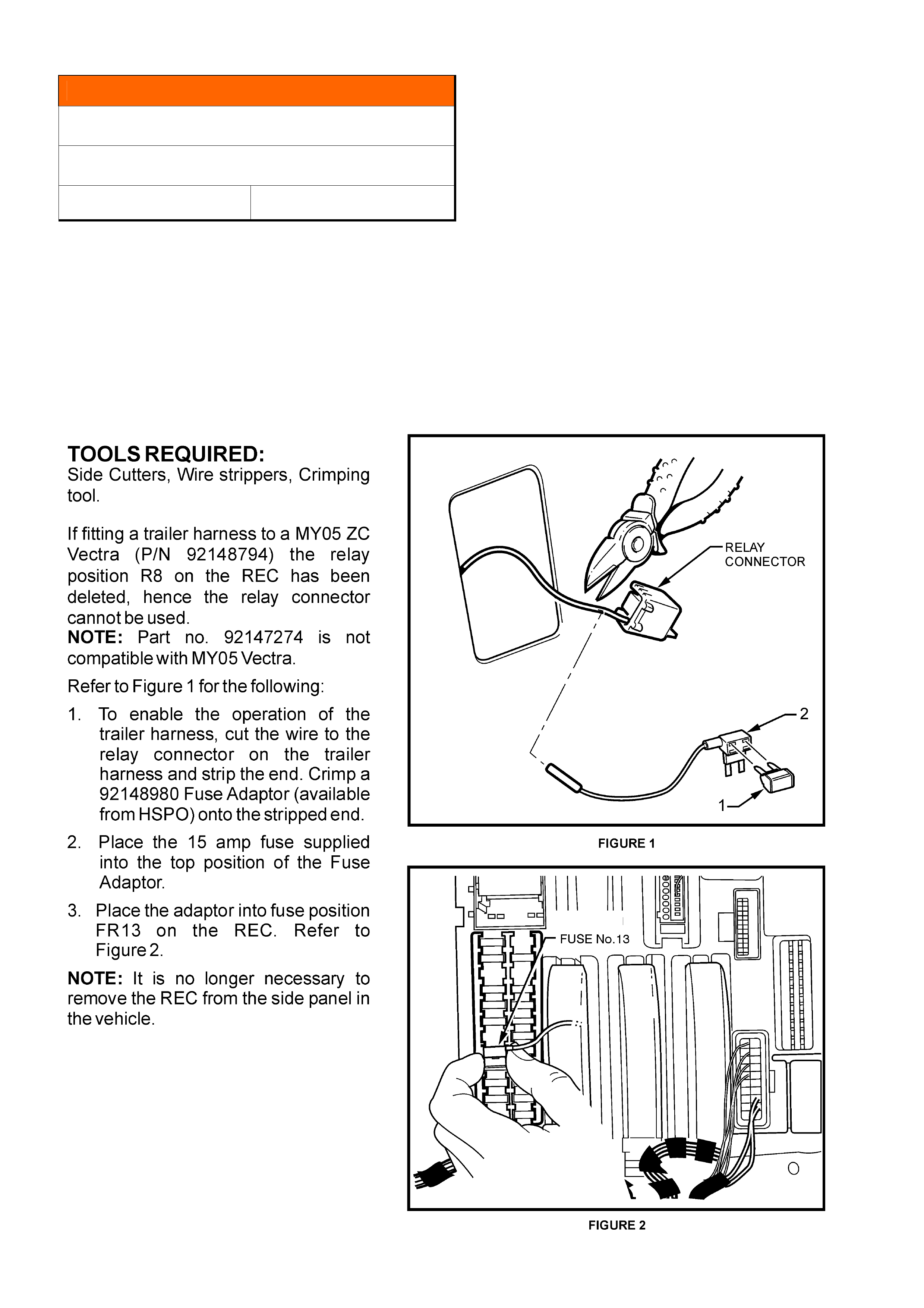
HOLDEN SERVICE TECHLINE _______________________________________________________________FEBRUARY, 2005
5
SERVICE FIX
Fuel Gauge Will Not Display Full After
Filling The Fuel Tank
VZ Gen III Ute
Group 12 Ref. No. TL0844 - 0501
CONDITION
Reports have been received of the fuel gauge not
displaying full after refilling the fuel tank.
CAUSE
The fuel gauge section of the Engine Control Module
calibration.
CORRECTION – Production
A revised fuel gauge calibration was programmed into
vehicles in production from the following breakpoint:
ISOVIN: Built Date:
**********L390626 21/01/2005
CORRECTION – Service
To rectify this condition it will be necessary to:
1. reprogram the PCM via the standard SPS process
using TIS 2000 version 58 or later and
2. reprogram the instrument cluster fuel gauge
calibration using Tech 2 with software version
13.8.
WARRANTY CLAIM INFORMATION
Description Reprogram PCM &
Instrument cluster
Labour Op. No. N000478
Time 0.6 hr
Failure Code N0057 Registers incorrectly
SERVICE FIX
Fuel Gauge Inaccuracy
VZ / WL V6 Sedan and Wagon
Group 12 Ref. No. TL0845 - 0501
CONDITION
Reports have been received of the fuel gauge not
displaying accurately at the lower section of the gauge.
CAUSE
Variation of the fuel gauge output calculated by the
Engine Control Module (ECM).
CORRECTION – Production
A revised fuel gauge calibration was programmed into
the Engine Control Module in vehicles from the
following breakpoint:
ISOVIN: Built Date:
L382346 09/12/04
CORRECTION – Service
To rectify this condition it will be necessary to:
1. reprogram the ECM via the standard SPS process
using TIS 2000 version 58 or later and
2. reprogram the instrument cluster fuel gauge
calibration using Tech 2 with software version
13.8.
Note: In addition to the above, if the vehicle was built
prior to the 06/10/04 (L345644), refer to Service
Techline number TL0809-0410 published in issue 10,
Nov. 2004, to ensure the fuel sender float arm is not
bent.
WARRANTY CLAIM INFORMATION
Description Reprogram ECM &
Instrument
Labour Op. No. N000475
Time 0.6 hr
Failure Code N0057 Registers incorrectly
HOLDEN SERVICE TECHLINE _______________________________________________________________FEBRUARY, 2005
6
SERVICE FIX
Hill Descent Control Icon Displayed When
Shifting Gear
VZ (non AWD)
Group 12 Ref. No. TL0843 - 0501
CONDITION
Reports have been received of the Hill Descent Control
Icon being displayed in the instrument cluster when
shifting from Park to Reverse to Drive
CAUSE
Instrument cluster operating software.
CORRECTION – Production
The instrument cluster software has been revised to
rectify this condition from the following vehicle
breakpoint:
ISOVIN: Built Date:
**********L366285 10/11/04
CORRECTION – Service
To rectify this condition reprogram the instrument
cluster operating software via the standard SPS
process using Tech 2 and TIS 2000 version 57 or later.
WARRANTY CLAIM INFORMATION
Description Reprogram instrument
cluster
Labour Op. No. N312700
Time 0.3 hr
Failure Code N0057 Registers incorrectly
SERVICE FIX
Service Reminder Incorrect
VZ V6 Sedan, Wagon and Ute
Group 12 Ref. No. TL0831A - 0501
This Techline supercedes the previous one in Issue
11, Dec, 2004. It is revised by adding procedure for
reconfiguring instruments.
CONDITION
Reports have been received of the 10,000 km service
reminder being displayed in the instrument cluster
instead of the 15,000 km.
CAUSE
Incorrect programming of the instrument cluster during
the production process.
CORRECTION – Production
The programming process has been revised to rectify
this condition from the following vehicle breakpoints:
ISOVIN: Built Date:
Sedan **********L313609 24/11/04
Wagon **********L373979 24/11/04
Ute **********L371431 24/11/04
CORRECTION – Service
To rectify this condition perform the following steps;
Step 1.
Using Tech 2 enter the configuration sub menu (an
example displayed below) within the instrument cluster
programming menu.
Step 2.
Scroll down to the Engine Type.
Step 3.
Select Modify and select V6.
Step 4.
Select Program.
Configuration
(5) 2005 VZ and WL Series
Instrument
Country Australia/NZ
Engine Type (Select Engine)
Speedometer 6000
SRS Configuration 6 Loop SRS
Transmission Type 4 Speed Auto.
Police Mode No
Seat Belt Warning On
-----------------------------------------------1/7-------
A
bort Modify Program
HOLDEN SERVICE TECHLINE _______________________________________________________________FEBRUARY, 2005
7
Step 5.
Inspect the instrument cluster, and reset the service
interval using Tech 2 if required.
WARRANTY CLAIM INFORMATION
Description Reprogram instrument
cluster
Labour Op. No. N312700
Time 0.3 hr
Failure Code N0057 Registers incorrectly
DIAGNOSIS HINT
RH Lower Dash Panel Insulator Rattle
AH Astra
Group 1 Ref. No. TL0849- 0501
CONDITION
Rattle emanating from the RHS lower IP panel while
driving over rough roads.
POSSIBLE RECTIFICATION
Remove the insulator trim and refit with the left front
corner secured above the bracket protruding from the
HVAC casing as shown blow.
Note: An alternative is to drill a hole through the
insulator trim in line with the hole in the HVAC case
bracket. The insulator trim can then be secured using
a cable tie or an additional clip.
Fig 1. Shows insulator trim fitted above HVAC case
bracket.
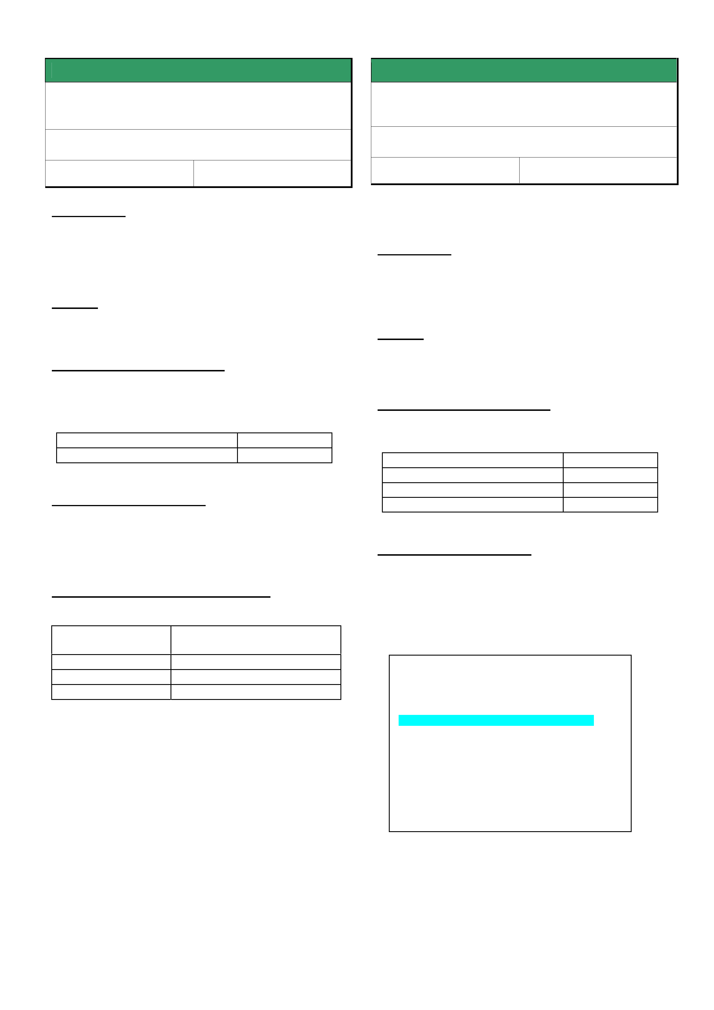
DIAGNOSIS HINT
Brake Fluid Discoloured
VY2, WK, V2. – All with amber coloured
brake fluid
Group 5 Ref. No. TL0824- 0501
CONDITION
Some dealer PIRs describe a fungus like deposit
visible in the brake fluid reservoir (Refer Figure 1).
The condition has only been observed since the
introduction of the amber coloured brake fluid ( Sep
2003.)
This condition has not previously been detectable due
to the green dye which was added to the brake fluid.
Figure 1.
CAUSE
Laboratory investigations have found the deposits are
made up of small amounts of additives that have been
extracted from the reservoir cap material by the action
of the brake fluid.
CONCLUSION
It has been determined that these deposits have no
effect on the brake system performance and integrity,
therefore DO NOT flush the brake fluid lines for this
condition.
HOLDEN SERVICE TECHLINE _______________________________________________________________FEBRUARY, 2005
8
SERVICE FIX
Blaupunkt 520 / 2020 CD Player
Inoperative Due To CD Not Ejecting
SB / JR / TS / TT / JS / XC /
GROUP 12 TL0479A-0501
This Techline supercedes the previous one in Issue
7,July 2003. It is reissued to revise the breakpoint (FD
reference number).
PROBLEM DESCRIPTION
Customers may complain of Blaupunkt 520 & 2020 CD
players becoming inoperative due to CD’s not ejecting.
After investigating the root cause Blaupunkt have
made a software revision to rectify this condition.
PRODUCTION RECTIFICATION
Blaupunkt implemented the software revision in all CD
players fitted to vehicles at the Port Of Entry on the 1st
of April 2004.
SERVICE RECTIFICATION
If you have a customer who presents a vehicle with the
above condition the following steps should be
performed.
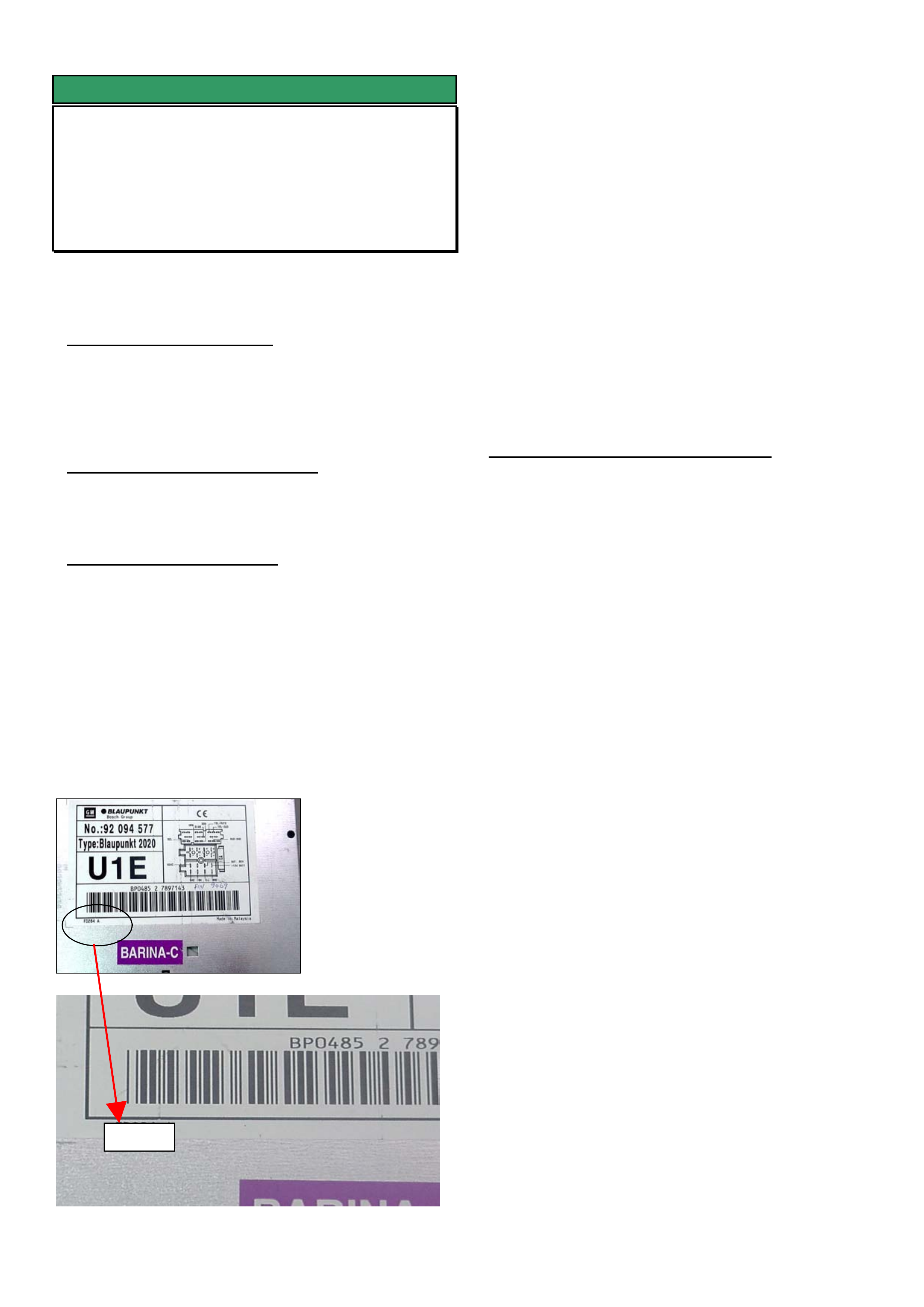
Step 1. Determine if the CD player is pre or post
break point by removing it and inspecting the bottom
left corner of the label attached to the top cover for the
FD number. Refer photographs below.
Pre breakpoint units have an FD number below
FD482. Post break point units have an FD number
FD482 or higher.
If unit is Pre breakpoint go to Step 2.
If unit is Post breakpoint go to Step 3.
Step 2. If the CD player is pre break point,
contact Blaupunkt as per the Special Warranty
Component Replacement Requirement section in
SIP and request approval to replace.
Step 3. If the CD player is post break point,
removing it from the vehicle to inspect the label will
have rectified the condition (disconnecting the power
supply).
Refit the CD player, check the operation and submit a
PIR indicating the FD number on the label and the
serial number stamped into the side of the CD player
case.
WARRANTY CLAIM INFORMATION
Use Labour Times information in Warranty Information
section of current PV SIP CD
FD482
HOLDEN SERVICE TECHLINE _______________________________________________________________FEBRUARY, 2005
11
INFORMATION
Tech 2, TIS 2000 Model Year Selection
ALL MODELS
GROUP OB TL0852-0501
This Techline is to clarify the correct procedure for
model year selection when using Tech 2 or TIS 2000.
For many programming operations and diagnostics
carried out using Tech 2 and TIS 2000 it is critical
that the correct model year is selected. This can be
easily identified by the tenth character of the VIN.
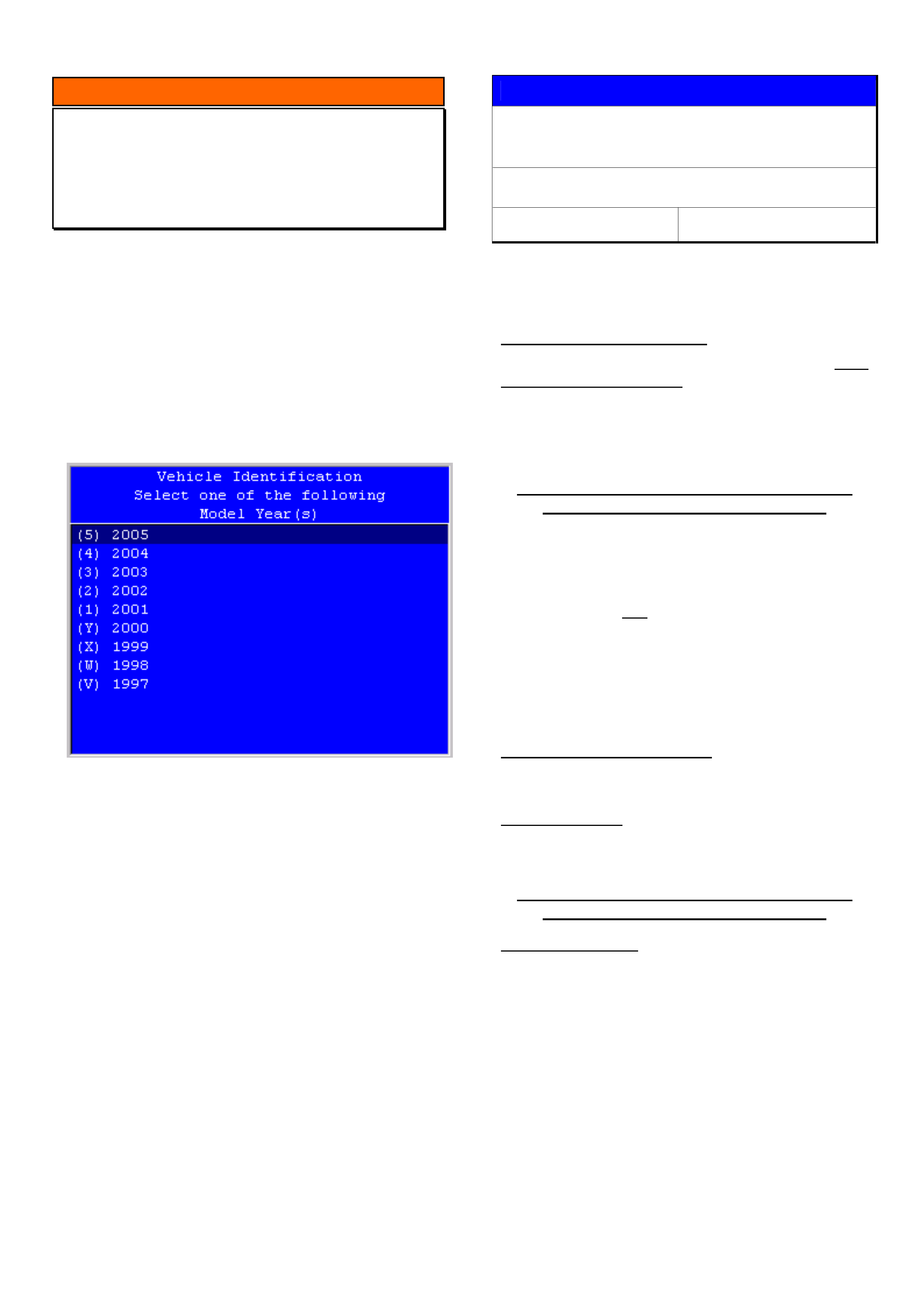
The screen below is an example of the Tech 2 Model
Year selection screen. The Numbers and letters on
the LH side in brackets are the values of the tenth
digit of the VIN for that model Year.
SERVICE PROCEDURE
Oil Filter Cap – Care During Removal and
Replacement (Cartridge Type)
TS & XC (X18XE1 or Z18XE Engines)
Group 6A Ref. No. TL0342A - 0501
This techline is repeated from 2002 as the problem
described below continues to occur.
PROBLEM DESCRIPTION
PIR’s have reported damage to the oil filter cap used
on cartridge type oil filters.
Damage (cracking) may occur on oil filter housing
caps during removal - if the cap is over-torqued when
a filter cartridge is replaced during regular
maintenance servicing.
Ensure only 15Nm is applied to the filter cap
when an oil filter cartridge is replaced.
All X18XE engines are fitted with cartridge type oil
filters.
Z18XE1 engines are fitted with two types of oil filters:
• Cartridge type – which requires the removal of the
filter housing cap to remove and replace the filter
element;
• Screw-on type – which requires only the filter
assembly to be removed and replaced.
Screw-on type oil filters were introduced to Z18XE
engines from: engine No Z18XE20V00605
SERVICE RECTIFICATION
Summary: Adhere to correct torque specification and
ONLY use the tools recommended below.
TORQUE SPEC.:
Do NOT over-torque the oil filter cap when fitting a
new oil filter cartridge.
Ensure only 15Nm is applied to the filter cap
when an oil filter cartridge is replaced.
REMOVAL TOOLS:
When removing filter housing caps on engines with
the cartridge type filter, use ONLY a 24mm ring
spanner or socket. This fully supports the cap
material and allows removal without damage to the
cap.
TIS 2000 drawings showing the use of a ratchet
handle and square drive special tool – these are
shown ONLY for the screw-on type oil filter fitted to
engines after the breakpoint shown above.

HOLDEN SERVICE TECHLINE _______________________________________________________________FEBRUARY, 2005
12
SERVICE FIX
DTC’s P0700, P0715, P0720
ZC with V6 & A/T
Group 7B Ref. No. TL0737- 0501
CONDITION
Customer may complain of “no shifting” or “incorrect
shifting” of transmission ratios.
DTC’s P0700, P0715 or P0720 may be stored (one
or all of the DTC’s).
CAUSE
It is possible that moisture has entered the speed
sensor connector, causing an incorrect or interrupted
signal.
CORRECTION – Production
Protective grease has been applied to speed sensors
from:
Trans. Serial No.: Built Date:
03MV735125 06/01/04
CORRECTION – Service
1. Disconnect the speed sensor connector and dry
out any moisture present.
2. If there is no evidence of corrosion or damage to
terminals apply grease 09163339 to connector to
stop future moisture entry.
3. If corrosion or damage is evident then replace
sensor. Also apply grease 09163339 to
connector to stop future moisture entry.
PARTS INFORMATION
Part No.: Description: Qty:
09163339 Grease. NYOGEL
760G 25 gm tube
1
93173888 speed sensor 1
WARRANTY CLAIM INFORMATION
Use Labour Time information in Warranty Information
section of current PV SIP CD.
NOTE: If there are re-occurences of the original
customer shift complaints together with the
above DTC’s, proceed as follows:
• Remove transmission valve body cover to
inspect for possible coolant entry to transmission
via the radiator oil cooler – which (in rare cases)
may cause the DTC’s to set.
NOTE: Remove the valve body cover
CAREFULLY and inspect for any water, or white
sediment in the cover. If water or white sediment
is evident, the radiator must be replaced, and
TAS should also be contacted for further
diagnostic information before any additional
work is carried out.
NOTE: Radiators with revised oil cooler sealing were
introduced into vehicle production from:
Ellesmere Port:
ISOVIN: Built Date:
W0L0ZCF6848035197 not available
Russelsheim:
ISOVIN: Built Date:
W0L0ZCF3541042598 not available

HOLDEN SERVICE TECHLINE _______________________________________________________________FEBRUARY, 2005
13
DIAGNOSIS HINT
Fluid Leak Diagnosis Using Black Light And Dye
All Models
Group: OB Ref. No. TL0837- 0501
This techline is repeated from year 2000 techlines.
The information provided in this techline is to assist Dealers in performing thorough and accurate diagnosis of
fluid leaks prior to commencing any rectification work or removing major components.
Components must NOT be replaced for “leaks” without thorough definition of leak sources.
Use of Black Light Dye and Black Light is highly recommended to trace leak sources. For extensive information
on the use of Black Light and Black Light Dye, refer to the following information repeated from a previous All
Dealer Letter.
Holden strongly recommends the use of the black light and dye method to diagnose fluid leak sources. This
method of leak detection is a proven, reliable method that identifies the specific leak source and/or location.
The black light and dye method can be used for various types of leak detection, when used with the appropriate
tracer dye it can be used for detecting engine and transmission fluid leaks, Refrigerant leaks, fuel leaks, and
coolant leaks.
The following pages provide answers to technicians’ questions about the various aspects of black light and
tracer dye, and how dealerships may use this tool to their advantage.
Black Light & Tracer Dye and Accessories
There are different types of tracer dye for different applications, plus for air-conditioning systems, an
injector is required to infuse the dye into the system. The following tracer dyes and accessories are
available from SPx Australia. Other equivalent products may be used in their place.
Contact details for SPx Australia – Ph.: (03) 9544 6222; Fax: (03) 9544 5222.
Application Part Number
Black Light Leak Detection
Lamp
16296
Replacement Black Light Bulb
AU 512
R134a Air Conditioning Tracer
Dye
(24 X 8ml bottles)
J41447
R12 Air Conditioning Tracer
Dye
(24 X 8ml bottles)
J39475
R134a Air Conditioning Injector
J41459
R12 Air Conditioning Injector
J41709
Petrol & Diesel Engine Fluid and
Transmission Fluid Tracer Dye
(24 X 1 oz bottles)
J28431-B
Coolant Tracer Dye
(24 X 1 oz bottles)
J29545-6A
Multi purpose dye
(engine oil, transmission & power
steering fluid, diesel & petrol)
16268

HOLDEN SERVICE TECHLINE _______________________________________________________________FEBRUARY, 2005
14
Black Light & Tracer Dye Useage Information
The following pages will answer most questions you may have about using Black Light and Tracer Dye.
Summary of the steps involved in detecting a fluid leak using black light and dye:
Pour specified amount of dye into the system.
Road test the vehicle under normal operating conditions, to allow the dye to mix with the host fluid/gas.
Define the leak source by directing the Black Light towards the suspect area. The fluid leak will appear as a
brightly coloured path leading to the source. Note: The colour of the dyed fluid can be checked on the dipstick,
or other component directly in contact with the host fluid/gas.
Repair fluid leak cause and recheck to ensure that leak has been rectified.
General Information
How much dye do you use? The following information is given as a guide only. Always refer to the label on the
bottle.
Engine, Transmission, Fuel
J28431-B Engine & Trans. Fluid Dye should be used as follows:
Petrol Engine Oil - 7.4ml per 3.79litres of oil (¼oz per 4-5 quarts)
Diesel Engine Oil - 7.4ml per 3.78litres of oil (¼oz per 4 quarts)
Automatic Trans. Fluid - 14.8ml per 5.68litres of fluid (2x¼oz per 6 quarts)
Manual Trans. Fluid/Oil - 7.4ml per 5.68litres of fluid (¼oz per 6 quarts)
Petrol or Diesel Fuel - 7.4ml per 7.57litres of fuel (¼oz per 2 gallons)
A/C Systems
J41447 R134a A/C Dye should be used as follows:
R134a A/C System - 7.4ml per A/C system (¼oz per system)
J39475 R12 A/C Dye should be used as follows:
R12 A/C System - 7.4ml per A/C system (¼oz per system)
Power Steering
J28431-B Engine & Trans. Fluid Dye can be used in Power Steering as follows:
Power Steering Fluid - 7.4ml per 5.68litres of fluid (¼oz per 6 quarts)
Engine Coolant Systems
J29545-6A Coolant Dye should be used as follows:
Coolant System Radiator Fluid - 7.4ml per 15.14 litres (¼oz per 16 quarts)
Note: These amounts are based on various tests - there may be occasions when good fluorescence is not
obtained with these amounts of dye, due to the condition of the host oil/fluid or the nature of certain additive
packages in the oil/fluid itself. If this occurs, use additional dye.

HOLDEN SERVICE TECHLINE _______________________________________________________________FEBRUARY, 2005
15
Q A
Do you need to use the
Fluorescent Enhancer Safety
Goggles?
Yes - they not only protect the technician, but also visually optimise the
dye fluorescence for enhanced leak detection. They are scientifically
designed to enhance fluorescence by eliminating light at wave lengths
that might interfere with the eye’s ability to view the dye’s fluorescent
light emission. Once you look at the dye with and without the goggles,
you will see the difference.
What life does the dye have
when left in coolant, ATF,
R12 and R134a refrigerant?
Indefinite - unless the ATF is “burnt” in an A/T clutch failure or if here is
an A/C compressor failure.
What life does the dye have
when left in engine oil?
Depends on how dirty the oil was when the dye was added. In clean petrol
engine oil, it will last 500+km. In diesel engine oil, it will not last as long
because of rapid carbon build-up.
Are there any adverse effects
of leaving dye in systems too
long?
None - and A/C dyes especially are very thermally stable and should last
100,000 km.
Is there a preferred method
of cleaning the dye from a
vehicle, if spilt?
IMPORTANT - Do NOT get dyes on any painted surfaces - use guard
covers when pouring dyes into any vehicle system or injecting A/C dyes. A
good cleaning solvent should clean any dye off any metal surfaces. A/C
dyes cannot be cleaned off hoses or plastic components.
What is the shelf life of the
dyes?
Indefinite, but it is recommended they be used within five years.
PETROL & DIESEL ENGINE & TRANSMISSION OIL LEAKS
Use J28431-B dye in quantities as specified in “General Information” section.
Putting dye into oil that is fairly clean will achieve the best fluorescence for le ak inspection because the greater
the carbon build-up in the oil, the more difficult to obtain good fluorescence from the dye. Therefore, if the oil
appears to be extremely dirty on the dipstick, additional dye may be required to obtain good fluorescence and
can be added without harm to the engine.
Q A
How do I know if the dilution
ratio of dye added is correct?
After adding dye at the recommended dilution ratio, operate the engine 3 to
5 minutes to allow dye to mix with oil. Then check the oil dipstick with
black light for the yellow-green fluorescent glow of the oil/dye mixture.
What is the proper procedure
for adding dye to the engine?
With the engine OFF. This will prevent possible splashing of the dye over
an area of the engine that may need inspecting.
How long does it normally
take for the dye to work?
Most leaks will appear after operating the engine 5 to 10 minutes. However,
it is recommended that the vehicle be taken for a short road test in order to
allow the dye to penetrate all leaks.
How long will it take for the
dye to penetrate very small
pinholes or porosity leaks?
To accurately detect leaks of this type, the vehicle should be operated for 1
to 3 hours under normal operating conditions. Suggestion: If such a leak is
suspected, add dye to the engine oil. Then have the vehicle owner use the
vehicle for the time recommended above. The owner should then return for
leak inspection with the black light.
Do I have to clean engine NO! Under black light, all petroleum-based products such as oil, grease, and

HOLDEN SERVICE TECHLINE _______________________________________________________________FEBRUARY, 2005
16
Q A
surfaces prior to using the
dye?
ATF will fluoresce blue. The dye will penetrate surface oil, grease and grit
to leave a yellow-green fluorescent trace (under black light) at the source of
the leak.
Do I have to clean the engine
after repairing the leak?
YES! But only at the source of the leak in order to allow the technician to
operate the engine and then re-inspect the leak repair to insure the job was
done right the first time. Suggestion: The dye/oil mixture can be removed
by using any engine degreaser or solvent-type shop cleaner.
After adding dye to the
engine oil, is it necessary to
change the oil prior to
returning the vehicle to the
customer?
NO! The dye is 100% compatible with engine oil and can remain in the
system without harm until the next oil change.
How long will it take for
ATF dye to work?
Most leaks will appear after operating the transmission for 5 to 10 minutes.
However, it is recommended that the vehicle be taken for a short road test in
order to allow ATF dye to penetrate all leaks. NOTE: All other application
and leak-detection procedures remain the same as given under the Engine
Dye Section (above). It is not necessary to clean transmission exterior
surfaces prior to using ATF dye. To detect small pinhole or porosity leaks,
the vehicle should be operated for 1 to 3 hours. The ATF dye mixture
should be cleaned from the source of the leak, and it is not necessary to
change ATF after adding dye.
How long will ATF dye be
effective in the transmission?
Because the transmission remains fairly clean internally and does not have
the carbon build-up problem present in petrol and diesel engines, the ATF
dye will be effective as long as the ATF is not changed or the ATF is not
“burnt” or discoloured by a transmission failure. Remember to check the
dipstick with the black light prior to inspecting for leaks to check
fluorescence, and do not forget to check the ATF cooler line for leaks.
BRAKE SYSTEM LEAKS
Q A
Can I use a fluorescent dye
in a brake system?
Never use any type of a fluorescent tracer dye in a brake system.
POWER STEERING LEAKS
Q A
How much dye should I use
for finding power steering
leaks?
Check the fluid capacity of the power steering system. You will probably
need to add only a small amount of dye at a dilution ratio of 7.4ml (¼ oz) to
5.68l (6 quarts) of power steering fluid. Run the system, then check the cap
or dipstick for fluorescence with the black light.

HOLDEN SERVICE TECHLINE _______________________________________________________________FEBRUARY, 2005
17
FUEL SYSTEM LEAKS
When a fuel system leak is suspected, it is recommended that the vehicle being tested have a quarter tank or less
of fuel. Trucks and larger capacity systems should be estimated as close as possible in order to keep the dye
requirement at a minimum and to keep the test procedure as economical as possible. If a difficult leak is
suspected, adding more dye than normal (a higher concentration) will produce the best results and will not harm
the system.
Q A
How do I know if enough
fuel dye has been added?
Any dipstick device that can be inserted into the filler tube can be used and
then inspected for fluorescence with the black light.
On a fuel-injected (PFI)
vehicle, can I use the fuel
rail for injecting dye?
NO! The small volume of petrol that will receive the dye is probably
insufficient for the dye to show up at an “O” ring injector leak for example.
COOLANT SYSTEM LEAKS
Q A
What is the proper procedure
for adding dye to the cooling
system?
Add dye with the engine off and radiator “cold”. This will prevent splashing
of dye and possible false readings. Also, add the coolant dye directly into
radiator and not into the reserve/surge tank found on some vehicles.
How do I clean the coolant
with dye off the radiator and
engine surfaces?
Use water with detergent and a small scrub brush.
How can I check for a
suspected coolant leak into
the engine oil?
Perform test as follows:-
Pull the engine oil dipstick and confirm the blue fluorescence of the engine
oil with the black light. (This is oil to which no dye has been added.)
With the engine off and the radiator cold, pour coolant dye into the radiator,
and operate vehicle for at least one day to allow coolant to leak into engine
oil.
With the engine off, pull engine oil dipstick and fluoresce dipstick with
black light.
If coolant is leaking into the engine oil, the dipstick should show some green
fluorescent droplets of coolant. Also, the engine oil might fluoresce a slight
whitish blue colour instead of the normal strong blue fluorescence of engine
oil.

HOLDEN SERVICE TECHLINE _______________________________________________________________FEBRUARY, 2005
18
USING DYE IN R134a or R12 A/C SYSTEMS
When dye is injected into an A/C system and the system has been operated under full pressure for 5 to 10
minutes, the dye will remain in the system even though the R134a or R12 has been evacuated for a repair. The
only time R134a or R12 dye must be replenished is when the A/C system is flushed of refrigerant oil.
Q A
How do I put R134a or R12
dye into an automotive car or
truck A/C system?
Put 7.4ml (¼ oz) of dye in the dye injector reservoir, and use a refrigerant
source to inject the dye into the A/C system.
How long will it take the
R134a or R12 dye to circulate
through the typical
automotive A/C system?
Operating the A/C system under full pressure, it will take the dye
approximately 5 to 10 minutes to circulate through most A/C systems.
However, this does not mean that the A/C leak will show up in that time
period.
How long after putting
R134a or R12 dye into the
A/C system and running the
system under full pressure
can I begin looking for the
A/C leak with the black light?
This depends on the size and location of the leak. As the refrigerant escapes
under pressure, it carries with it a very small amount of refrigerant lubricant.
This trace of lubricant is what you are looking for with the black light.
Therefore, the size of the leak will determine how long it takes for the
lubricant dye to appear and fluoresce under the black light. A hose porosity
leak would, therefore, take longer to appear than a fracture/fitting leak.
Example: A high-pressure side leak may take over a week or more to have
enough refrigerant escape to affect the cooling capacity of the A/C system,
return the car to the customer, and tell them to bring it back for leak
inspection when they again notice a lack of cooling by the A/C system. When
this car returns, the refrigerant that has escaped will leave a trace of
refrigerant lubricant with dye, which is what you will be looking for with the
black light.
How do I know if I have a
leaky service valve on the
low-pressure side if I just
used that valve to put dye into
the A/C system?
After putting the R134a or R12 dye into the A/C system through the low-
pressure service valve, clean the valve with a solvent if the refrigerant taking
the dye into the A/C system did not clean off the service valve, sufficiently to
remove all trace of dye. Do this before starting the A/C system.
How do I clean the R134a or
R12 dye off A/C components
and engine surfaces?
Use any shop degreaser or solvent to clean dye off A/C components or
engine surfaces.
Are these A/C dyes
compatible with my
refrigerant recovery and
recycle equipment?
These dyes have been tested and proven compatible by major manufacturers
of recovery and recycle equipment. When refrigerant is evacuated from an
A/C system, a small amount of compressor lubricant is also removed from
the system. The R134a or R12 dye is in solution with the system compressor
lubricant, therefore, is separated in the recovery/recycle unit along with the
compressor lubricant. Because of the small amount of compressor lubricant
removed by the recovery/recycle unit, there is no need to add additional R-
134a or R-12 dye to the A/C system for future leak detection.
How do I know if a vehicle’s
A/C system contains dye?
Remove the low-side service port sealing cap and direct the black lamp into
the valve stem area. If you do not see dye/lubricant in this area, depress the
valve stem only for an instant to help bring out some lubricant with the
refrigerant. Again direct the black light at the valve stem for traces of the
fluorescent dye/lubricant. Clean dye off service port.
HOLDEN SERVICE TECHLINE _______________________________________________________________FEBRUARY, 2005
19
Q A
How do I check for
refrigerant leaks in the
evaporator when I cannot use
the black light to see the
leak?
Use the black light to fluoresce the drain hole and see if a trace of the yellow
green dyes has washed down with the condensation. When the evaporator is
removed from the vehicle, use the black light to determine the exact location
of the leak on the evaporator. Remember to check the fittings to and from the
evaporator to be sure they are not the cause of the leak.
How do I check for the
dye/lubricant when I cannot
directly shine the black light
on all suspected leak areas?
Use a mirror to reflect the black light to the underside of a fitting, hose or
component. Also if a mirror cannot be used, a white cloth can be used to
wipe the suspected area, and then fluoresce the cloth with the black light to
check for traces of the yellow-green dye.
Can the dyes remain in the
A/C system after it has been
used for the initial leak
detection?
Dyes can safely and effectively remain in the A/C system after the initial
repair. Dyes can be used to detect future refrigerant leaks and can only be
removed from the A/C system by flushing out the system compressor
lubricant.
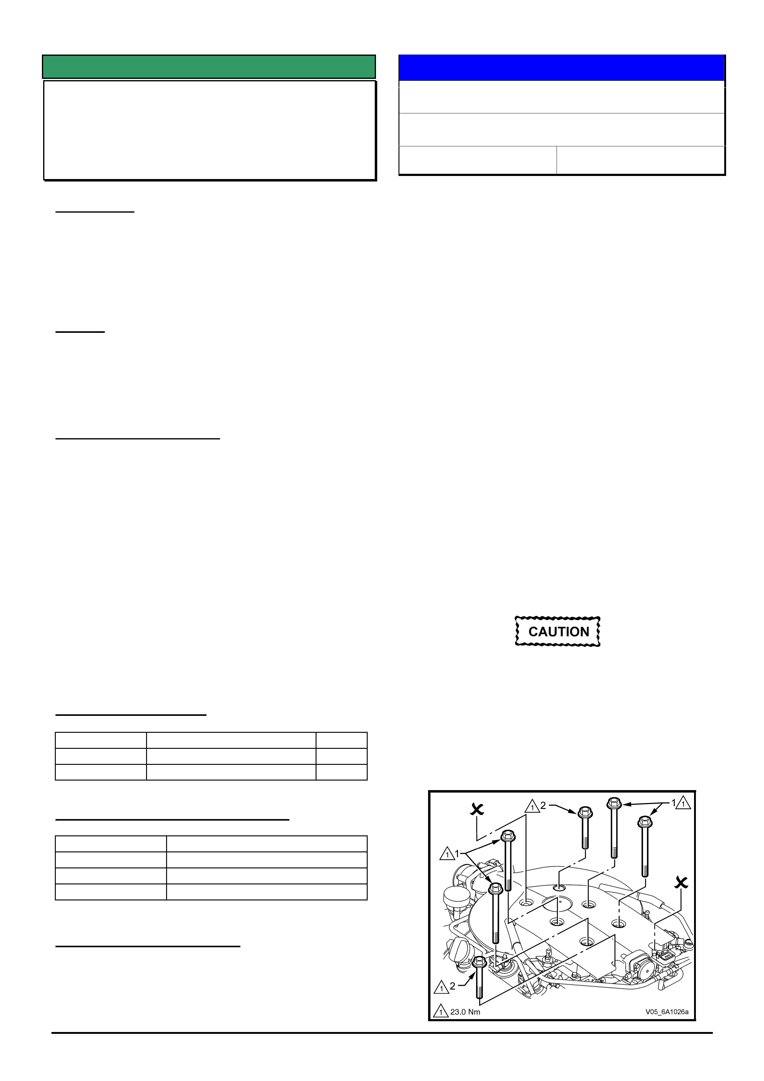
DIAGNOSIS HINT
Noise / Vibration With A/C Operating
VZ Series – V6
Group 2 Ref. No. TL0846- 0501
CONDITION
Any symptom of noise with the A/C operating.
POTENTIAL CAUSE
Compressor bracket mounting bolts/studs not
tensioned correctly.
SERVICE RECOMMENDATION
The compressor and compressor bracket
mounting torques must be checked before
replacing any components or commencing
further diagnostic work.
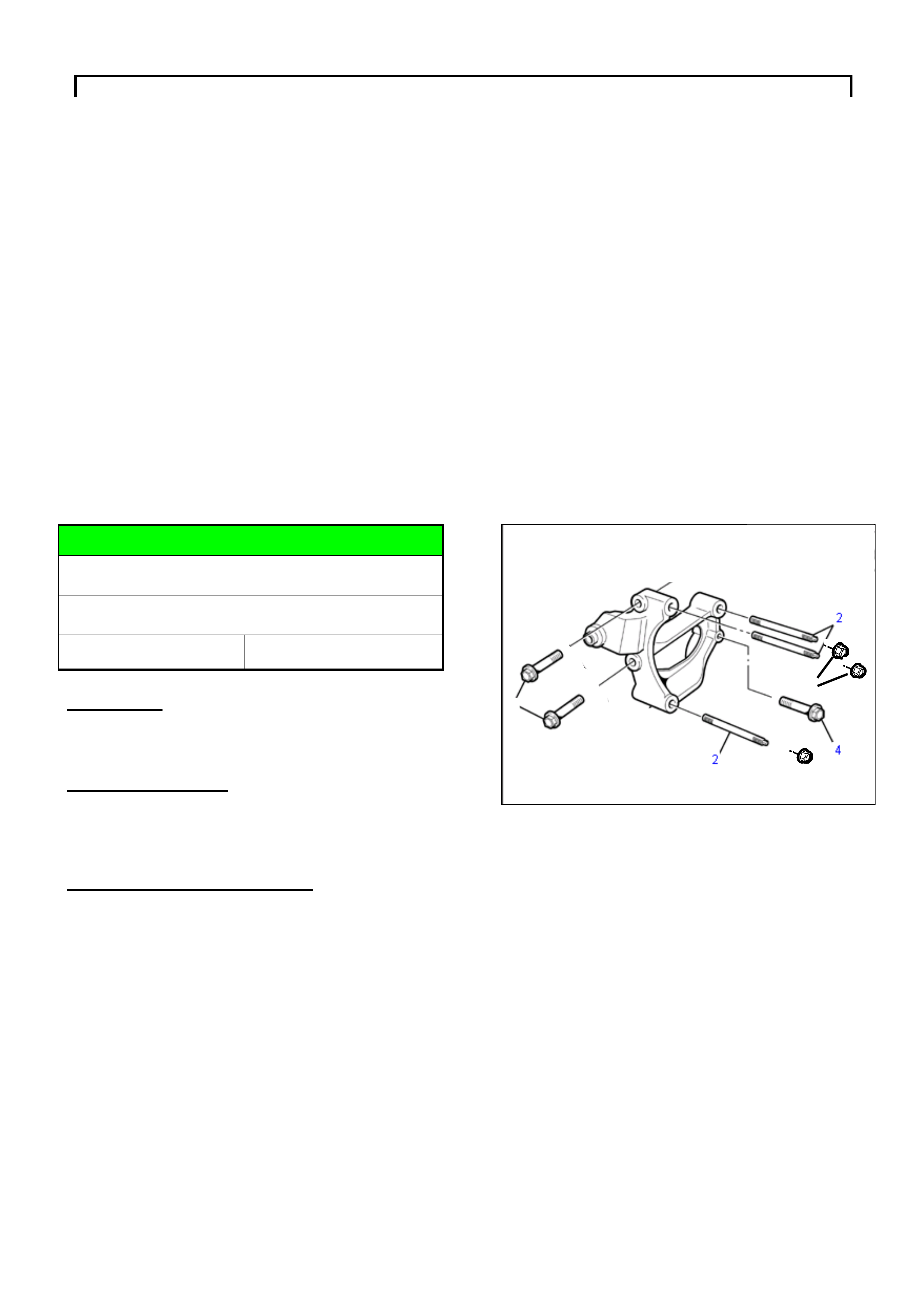
1. Torque A/C Compressor Bracket Front
Mounting Bolts (item 1 in Figure 1) - 58 +/-9
Nm.
2. Torque Studs Into Compressor Bracket
(item 2 in Figure 1) – 10 +/-2 Nm.
3. A/C Compressor To Bracket Attaching Nuts
(item 3 in Figure 1) – 22 +/-3 Nm.
4. A/C Compressor Bracket Rear Mounting
Bolt (item 4 in Figure 1) – 22 +/-3 Nm.
Figure 1. Compressor mounting bracket
3
3
1

HOLDEN SERVICE TECHLINE _______________________________________________________________FEBRUARY, 2005
20
INFORMATION
Holden Contacts and procedures
All Models
Group OB Ref. No. TL0679A- 0501
This Techline supercedes the previous one in Issue
3, April 2004. Revisions are shown in red.
This techline summarises some of the Holden
contact procedures and gives a quick reference
guide for contact numbers.
Security information.
To obtain security information for both Passenger
and LCRV vehicles the first step is to check
Lionheart. If the information is unavailable on
Lionheart then a completed security information
request form must be faxed through to the security
information department, as security information
cannot be given out by phone. Please note that
security information requests are processed by the
security information department and not TAS.
Please ensure you have the latest security
information request form, which is available on
Passenger Vehicle SIP for both Passenger and
LCRV. Contact details are listed below. There can be
up to a 4-hour turn around on requests however if the
information needs to be obtained from overseas, it
may take up to 24 hrs. Do not phone the security
information department unless you have not received
a response in the normal turn around time. For
further information please refer to ADL 63/99.
Parts inquiries and information
If any information or assistance is required in regards
to part numbers or Partfinder, please refer to the
Holden Help section in Partfinder.
Warranty Authorisation and enquiries
Warranty can only be authorised by your Aftersales
District Manager. Labour times information is
available on SIP or from the warranty department.
For any other warranty inquiries please contact
Warranty Administration.
TAS
Technical Assistance Service (TAS) is a service
provided by Holden to assist Holden Dealers in
problem resolution.
Contact to TAS must be made by a Nominated
Contact as outlined in Section 5 of the TAS
procedures manual. All techlines, dealer letters and
service information must be checked prior to
contacting TAS. The Nominated Contact must not
contact TAS until he/she has been fully involved with
the faulting vehicle and all Dealer expertise has been
exhausted. Problems should be escalated through
the Dealership to the senior technician/foreman
before contacting TAS.
TAS cases must be updated or closed within 30 days
unless a Dealer is waiting on a service fix to be
provided. It is the Dealers responsibility to update
cases. All cases should be recorded in the TAS
procedures manual, which should be referred to prior
to contacting TAS. Please note that an electronic
copy of the TAS procedures manual is also available
on passenger SIP.
All Daewoo TAS enquiries must be done by Fax.
Under no circumstances should you call TAS for
Daewoo enquiries.
Under no circumstances are TAS or other Holden
contact details to be supplied to customers or
independent repairers. TAS is a service restricted to
assisting Holden Dealer service departments.
Quick reference contact numbers
Air International Ph 1800 673 716
Australian Arrow Ph 03 9785 0792
Blaupunkt Ph 1300 307 036
Bosch Technical Assistance Ph 1800 025 462
Clarion Ph 1300 730 730
Fax 03 9551 0377
Customer Assistance Ph 1800 033 349
Dana Ph 02 9892 9237
Fax 02 9892 9310
www.spiceraxle.com.au
Delphi Ph 1800 335 777
Eurovox Ph 03 9237 0800
Fujitsu Ten Ph 03 9646 6008
Holden Assist Ph 1300 880 088
HSV Ph 03 9265 9500
Infomedia (SIP, Partfinder) Ph 1800 810 103
Panasonic Ph 02 9986 7635
PBR Diagnostic assistance Ph 1800 468 727
Petro-Ject Ph 02 9890 5701
Ph 02 9890 5244
Philips/Siemens-VDO Ph 1800 335 282
Salmat Ph 03 9358
2900
Security Information Ph 03 9647 2001
Fax 03 9647 2865
SPX Australia Ph 03 9544 6222
TAS Ph 1800 033 417
Fax 03 9647 2495
Email [email protected]
Warranty Ph 1800 033 487
Update
HOLDEN SERVICE TECHLINE ________________________________________________________________________________MARCH, 2005
4
Holden Techlines are written to inform technicians of conditions that may occur on some vehicles, and to provide information that could assist in the
proper service fix of a vehicle. If a condition is described, do not assume the service fix applies to a vehicle or that the vehicle will have that condition.
DIAGNOSIS HINT
Buzz Noise Caused By Steering Wheel
Adjusting Lever
VY, VZ, WK, WL
Group 9 Ref. No. TL0862- 0502
If an owner complains of a buzz type noise coming
from the steering column shroud area, one possible
cause for this could be the lack of clearance between
the steering column adjustment lever and the lower
plastic shroud as shown in Figure 1. Under certain
driving conditions the lever can vibrate against the
cover, resulting in a buzz noise.
To rectify, carefully bend the lever so it has clearance
to the plastic cover for all steering column positions.
i.e. from fully extended to fully retracted.
Figure 1. Shows potential area of contact
SERVICE FIX
Notchy Fore/Aft Movement on 6 & 8 Way
Front Seats
V2, VY & VZ Calais, WK, WL
Group 1 Ref. No. TL0847- 0502
CONDITION
On some vehicles fitted with 6 or 8 way power front
seats, there may be some roughness felt when moving
the seat through its full fore/aft horizontal travel.
CORRECTION - Service
After verifying that vehicle has the condition as
described above, perform the procedures A & B
shown on the following pages to both front seats.
PARTS INFORMATION
Part No.: Partfinder® Name Qty:
92138926 Dampener - front seat
adjuster track
1/seat
NOTE: Each dampener consists of one steel clip and 2
nylon friction components which will need to be
assembled as shown in illustration below.
WARRANTY CLAIM INFORMATION
Description Install dampener to seat adjuster
driveshaft – both front seats
Labour Op. No. C000541
Time 0.8 hr
Failure Code C0041 chatters
CORRECTION – Production
Seats (6 & 8 way type) with dampeners fitted to
driveshafts have been installed in vehicles from:
ISOVIN: Built Date:
**********L397250 07 Feb 2005
HOLDEN SERVICE TECHLINE ________________________________________________________________________________MARCH, 2005
5
Holden Techlines are written to inform technicians of conditions that may occur on some vehicles, and to provide information that could assist in the
proper service fix of a vehicle. If a condition is described, do not assume the service fix applies to a vehicle or that the vehicle will have that condition.
PROCEDURE A - Install dampener clip to driveshaft:
• Move seat to the mid position using seat
controls
Mid position is when the front of the track rails
are level.
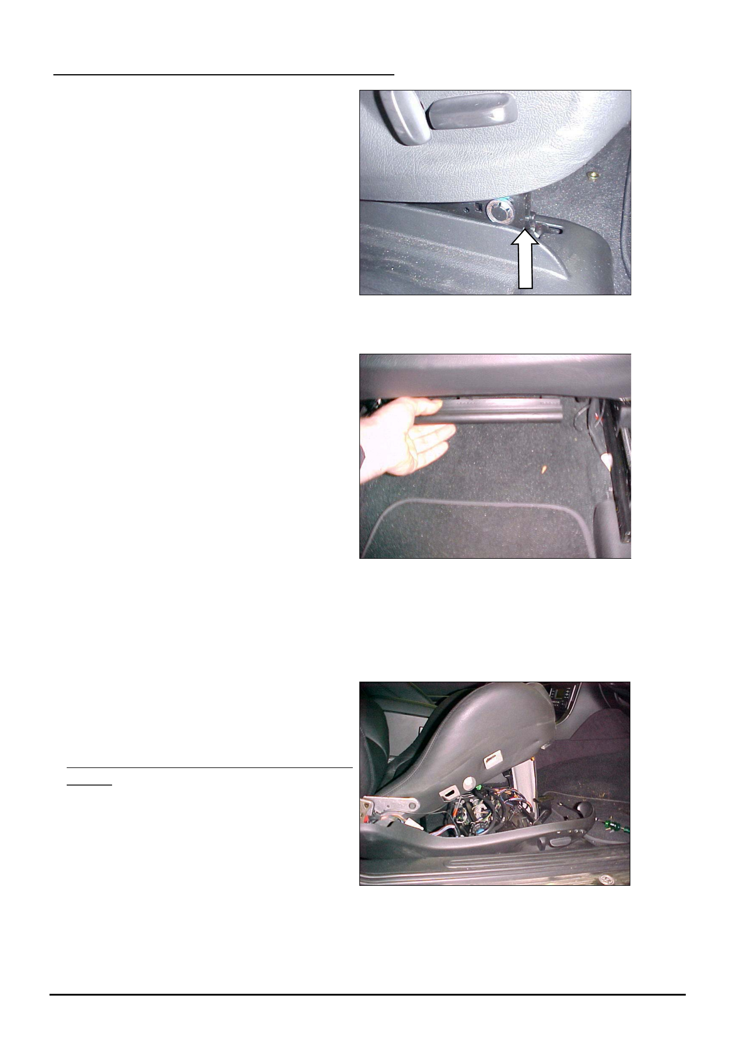
• Raise seat to the full up position using seat controls
• For older vehicles that do not have the cable
tray style wiring harness – release the under
seat nappy retainer.
• Remove the side cover
• Undo the two front seat frame to cushion mounts – 13mm AF Nuts, 2 off.
• Tilt seat backward being careful not to over
stretch any of the wires.
On Older vehicles with underseat nappy
retainer:
The nappy will catch on the track assembly as
shown. It is not necessary to completely remove
the nappy as this will protect the wires from
being stretched too far.
HOLDEN SERVICE TECHLINE ________________________________________________________________________________MARCH, 2005
6
Holden Techlines are written to inform technicians of conditions that may occur on some vehicles, and to provide information that could assist in the
proper service fix of a vehicle. If a condition is described, do not assume the service fix applies to a vehicle or that the vehicle will have that condition.
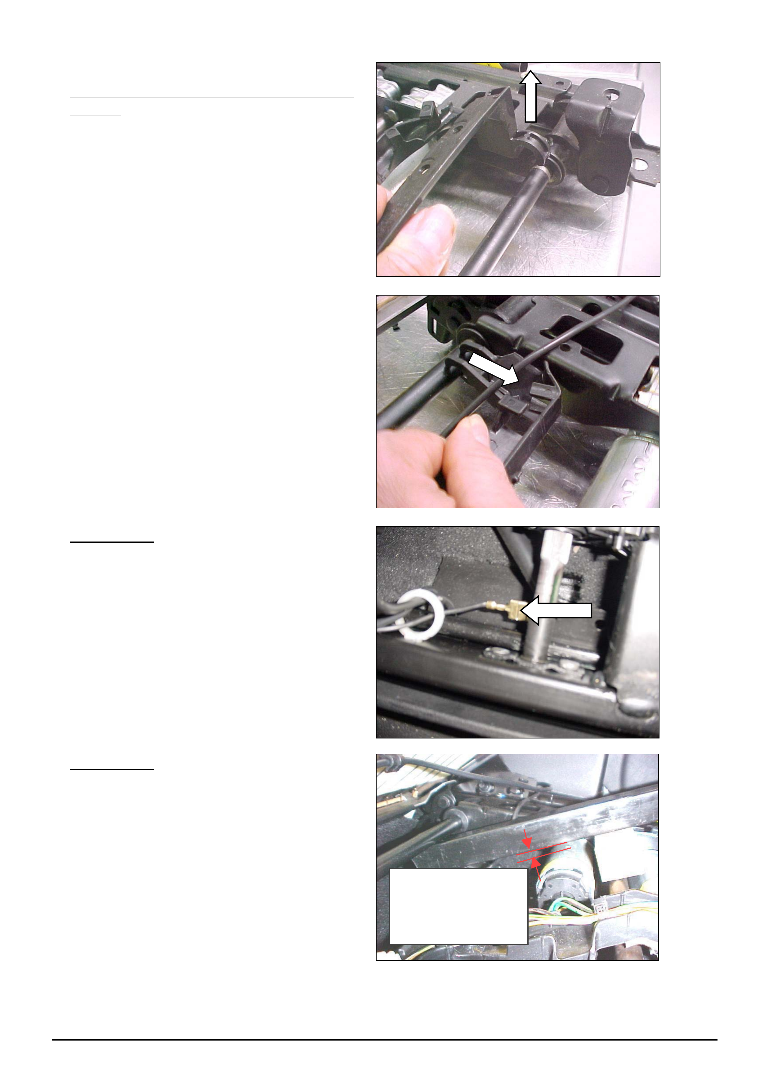
On Later vehicles with cable tray style wiring
harness:
(A). Un-clip the cable tray from the track as
shown by lifting the front clips
(B). Pull the cable tray forward to disengage
the rear clips
IMPORTANT
Ensure that the earth connection wire is
correctly connected at both ends – it should be
clipped to cushion frame and connected to the
terminal on the lower track rail.
IMPORTANT
• Obtain a length of steel tube, a tyre lever or
similar, to be used for fitting the dampener as
shown below. Hook one end of the lever under
the rear crosses shaft and place a suitable size
piece of timber in between the metal bar and
drive shaft as shown. Ensure a 5mm min. gap
is present between the metal bar and lift motor.
This will ensure that the motor is not
damaged during fitment of the dampener.
Minimum 5mm
gap between bar
and motor
HOLDEN SERVICE TECHLINE ________________________________________________________________________________MARCH, 2005
7
Holden Techlines are written to inform technicians of conditions that may occur on some vehicles, and to provide information that could assist in the
proper service fix of a vehicle. If a condition is described, do not assume the service fix applies to a vehicle or that the vehicle will have that condition.
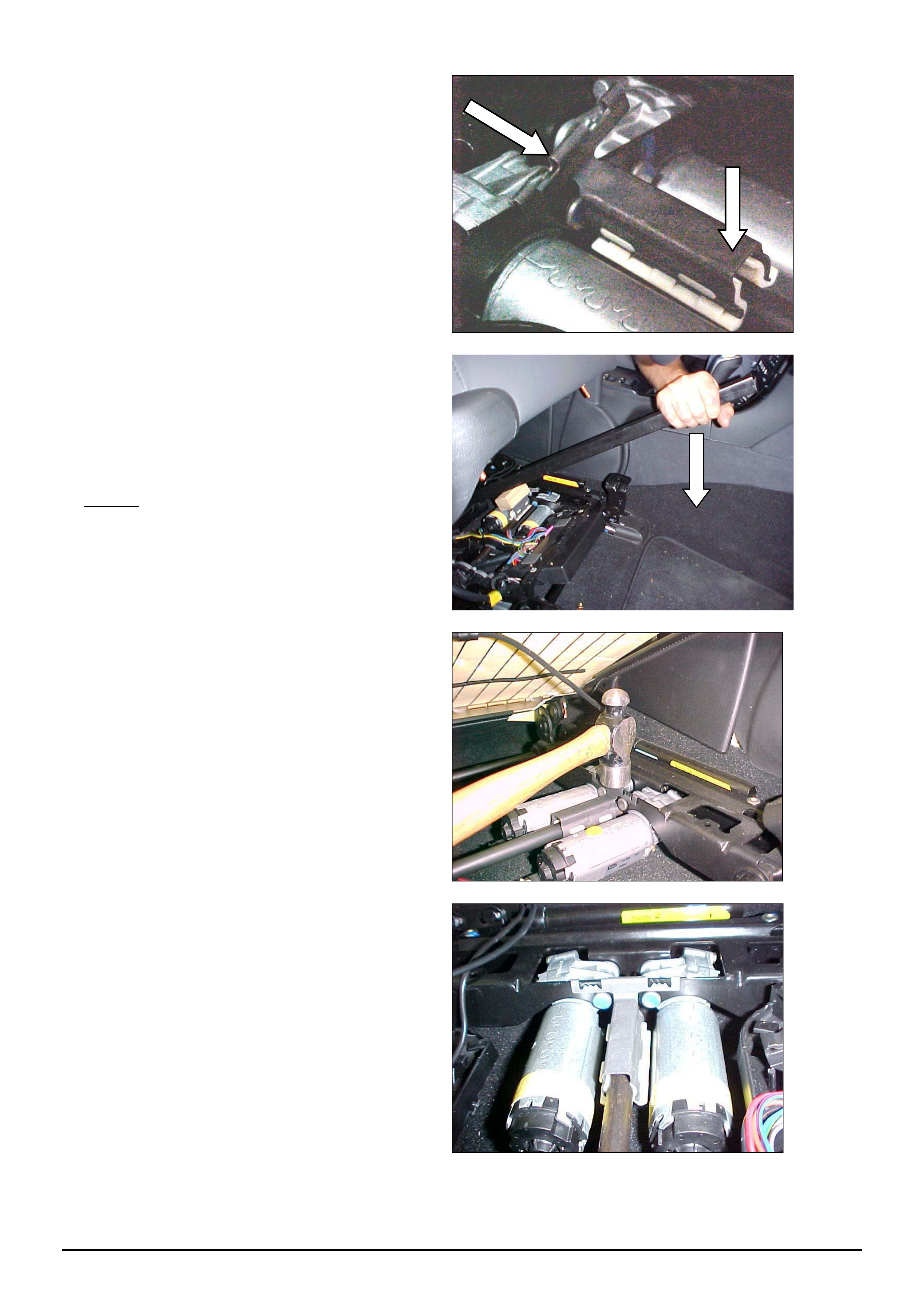
• Position the dampener by aligning the
retaining tang over the motor mount flange and
the friction pads over the drive shaft as shown.
• With the piece of wood on top of the clip to
protect the motor, push down on the lever until
the clip is pressed onto the drive shaft.
NOTE:
This photo shows the cable tray version with
cable tray disengaged and out of the way
• Tap the dampener retaining tang into place
with a hammer
This Photo shows the Dampener in final
position
HOLDEN SERVICE TECHLINE ________________________________________________________________________________MARCH, 2005
8
Holden Techlines are written to inform technicians of conditions that may occur on some vehicles, and to provide information that could assist in the
proper service fix of a vehicle. If a condition is described, do not assume the service fix applies to a vehicle or that the vehicle will have that condition.
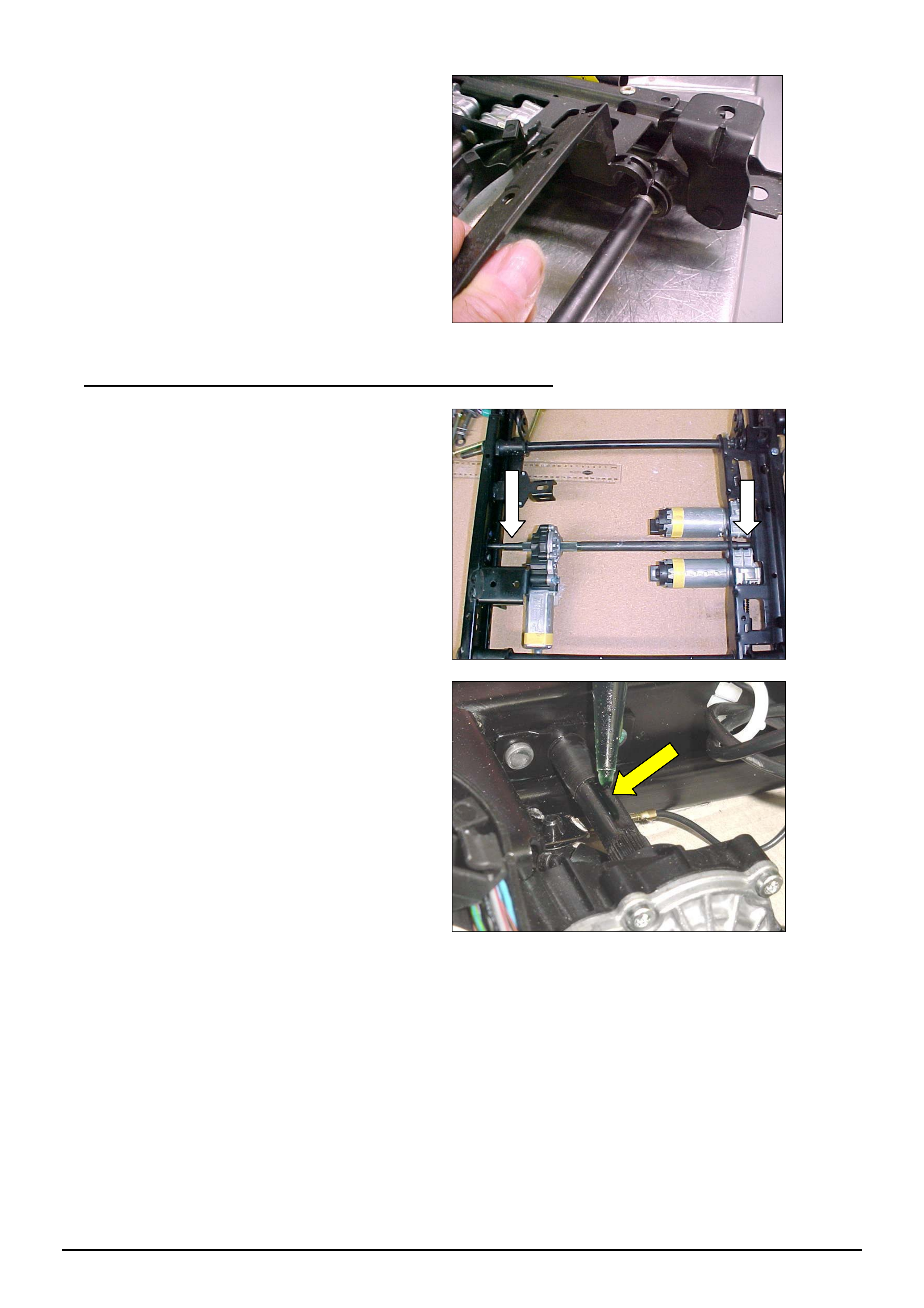
• Refit cable tray if applicable
PROCEDURE B – Eliminate slackness in driveshaft joints.
• Move the track until the driveshaft V
grooves are in the upper position.
• Apply Loctite 680 (or equivalent) to the
groove and work into the joint under the plastic
spacer.
Be sure to place paper under the area to protect
the carpet from any drips.
• Operate the seat back and forward several times for a distance of 100mm.
After this, DO NOT operate the seat for at least 1 hour to allow the loctite to set.
NOTE The seat may be occupied during this time
• Lower seat cushion onto mounts and tighten the attaching nuts to 24-32Nm
• Reattach under seat nappy clip where applicable.
• Refit side cover.
• Repeat procedure on other front seat.
HOLDEN SERVICE TECHLINE ________________________________________________________________________________MARCH, 2005
9
Holden Techlines are written to inform technicians of conditions that may occur on some vehicles, and to provide information that could assist in the
proper service fix of a vehicle. If a condition is described, do not assume the service fix applies to a vehicle or that the vehicle will have that condition.
SERVICE FIX
Transfer Case “Hash” Noise Reduction
VY Adventra & Cross 8
(GROUP 7B) TL0721-0502
CONDITION
It is possible for a “hash” noise (similar to a synchro
ring rattle noise) to be heard in the passenger
compartment. Reports say the condition may occur in
the range of 40 – 60 km/hr on light acceleration or
deceleration.
CAUSE
The noise heard is normal transfer case internal gear
and bearing noises which are transmitted into the
passenger compartment via the solid attachment of
the A/T shift cable to the transmission case.
CORRECTION – Service
Summary: After verifying that vehicle has symptoms
as described above, fit the new insulated shifter cable
bracket with new attaching screws.
To fit these parts, refer to Passenger SIP section 7C4
for service operation 2.2 – this procedure allows
removal of the A/T selector cable for access to the
cable bracket on the side of the transmission.
(The revised bracket is similar in appearance to the
original cable bracket – so its location and orientation
are easily defineable).
When attaching the cable bracket with the new screws
torque screws to 17±3 Nm.
PARTS INFORMATION
Part No.: Description: Qty:
92174776 Bracket Asm., Shifter Cable 1
11098091 Screw, Bracket Mtg. 2
WARRANTY CLAIM INFORMATION
Description A/T Cable Bracket Asm. - Replace
Labour Op. No. K503100
Time 0.6 hr
Failure Code K0040 Noisy
CORRECTION – Production
The revised A/T shift cable bracket with insulating
bushes is scheduled to be fitted to vehicles in
production. Breakpoint details will be published in a
future techline.
SERVICE PROCEDURE
Inlet Manifold Removal Procedure
HFV6 Engine - VZ & WL
Group 6A Ref. No. TL0868- 0502
The current Passenger SIP CD advises to “split” the
inlet manifold upper and lower parts when servicing
Cylinder head/s, Fuel injector, Ignition coils and Spark
plug servicing.
It is NOT necessary to “split” the inlet
manifold for servicing of these parts!
The inlet manifold can be removed as a complete
assembly – this removes the need for the intermediate
gasket to be replaced.
In addition – the gasket between the inlet manifold
assembly and the cylinder heads is a reuseable
design which does NOT have to be replaced unless it
is damaged!
Passenger SIP CD is currently being updated to show
these revised procedures which simplify the servicing
of the manifold and related components, and negate
the need to replace any gaskets (unless damaged).
A copy of the revised procedure for Inlet Manifold
Assembly Complete (Remove & Reinstall) is available on
the Holden LIONHEART dealer website. (refer Service
Techlines, 2005, Group 6A) Please refer to this revised
procedure until the Passenger SIP CD is updated.
Your attention is also drawn to Figure 6A1–10 in the
revised procedure regarding the manifold mounting bolts:
Do not loosen or remove the short bolts (8)
(70 mm) holding the upper intake manifold to
the lower. These bolts are at the front left and
rear right of the upper intake manifold.
Removal of these bolts (that hold the upper and lower
manifolds together) may result in intermediate gasket
damage and subsequent engine performance concerns.
HOLDEN SERVICE TECHLINE ________________________________________________________________________________MARCH, 2005
10
Holden Techlines are written to inform technicians of conditions that may occur on some vehicles, and to provide information that could assist in the
proper service fix of a vehicle. If a condition is described, do not assume the service fix applies to a vehicle or that the vehicle will have that condition.
INFORMATION
M/T Fault Diagnosis
6-Speed M/T (Gen III vehicles)
Group 7A Ref. No. TL0872- 0502
Technicians should be aware of additional 6-speed
M/T diagnosis information that has been made
available in All Dealer Letter DL 06/2005.
The information allows technicians to carry out
diagnosis on specific transmission complaints, and
complaints with related components that may be
confused as transmission faults.
Please refer to this letter for diagnosis information until
the information is released in the next Passenger SIP
CD.
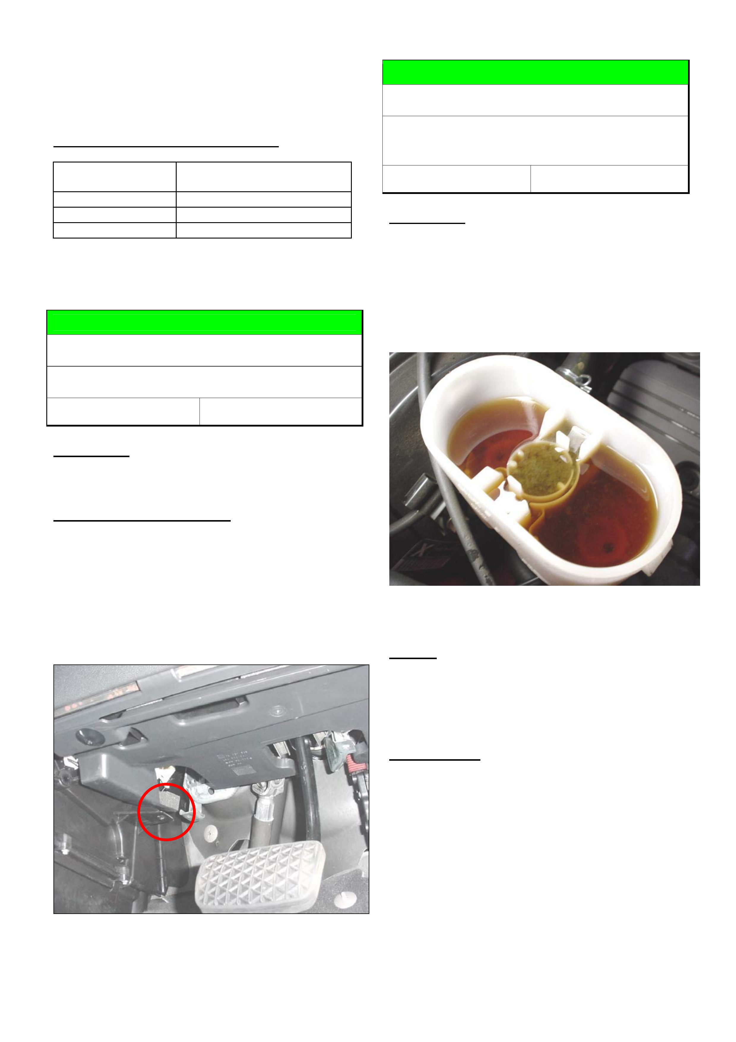
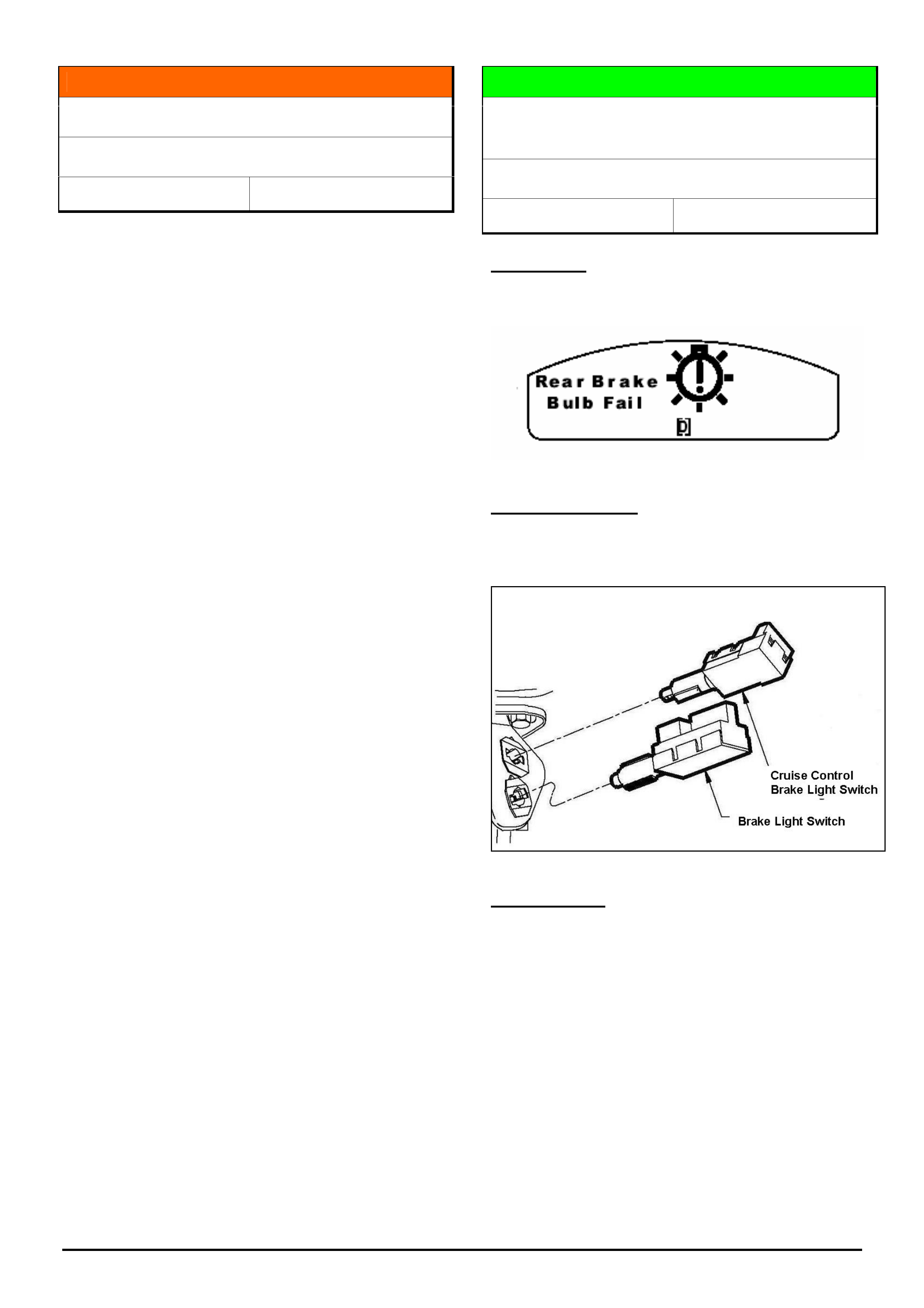
DIAGNOSIS HINT
“Rear Brake Bulb Fail” Warning Indication
Displays In Instrument Cluster
VZ, WL
Group 12 Ref. No. TL0870 - 0502
CONDITION
Rear Brake Bulb Fail warning indication displayed in
instrument cluster even though bulbs are working
POTENTIAL CAUSE
Incorrect adjustment of the cruise control brake switch
against the brake pedal.
CORRECTION
The correct switch adjustment is achieved by the
following procedure;
1. Twist the cruise control switch anticlockwise a
quarter of a turn to release the latch.
2. Push the switch until the barrel rests against the
brake pedal while the pedal is in its rest position.
3. Twist the switch clockwise to lock the barrel in
place (clearance from the barrel to the pedal
should be 0.7+ / - 0.5mm).
HOLDEN SERVICE TECHLINE ________________________________________________________________________________MARCH, 2005
11
Holden Techlines are written to inform technicians of conditions that may occur on some vehicles, and to provide information that could assist in the
proper service fix of a vehicle. If a condition is described, do not assume the service fix applies to a vehicle or that the vehicle will have that condition.
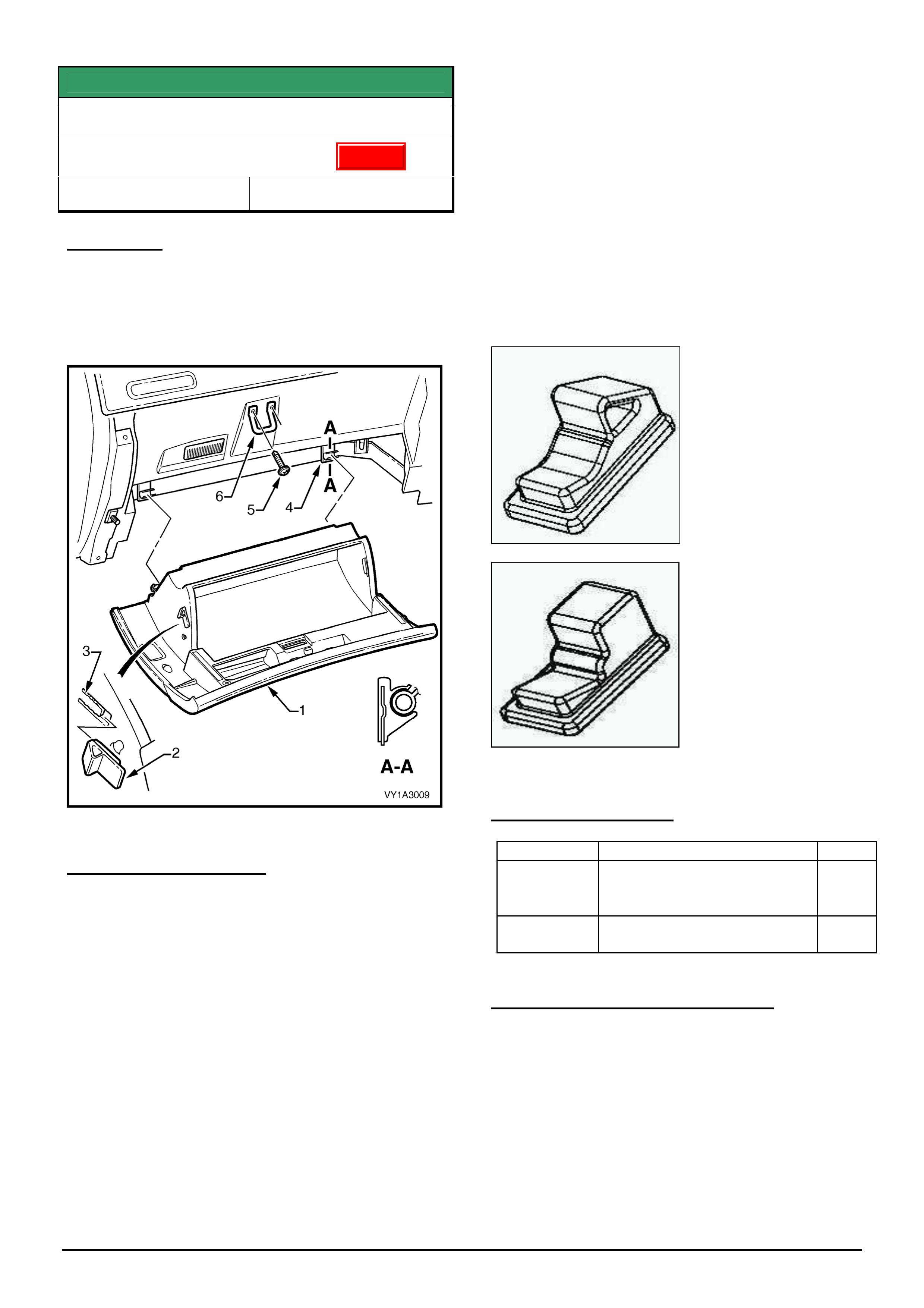
SERVICE FIX
Glove Compartment Door Opens Too Far
VY, VZ, V2 II & III, WK, WL
Group 1 Ref. No. TL0854- 0502
CONDITION
Glovebox door rubber bump stops may tear in
service. As a consequence, the glovebox
compartment swings fully downward when opened
and is not restrained by the stops.
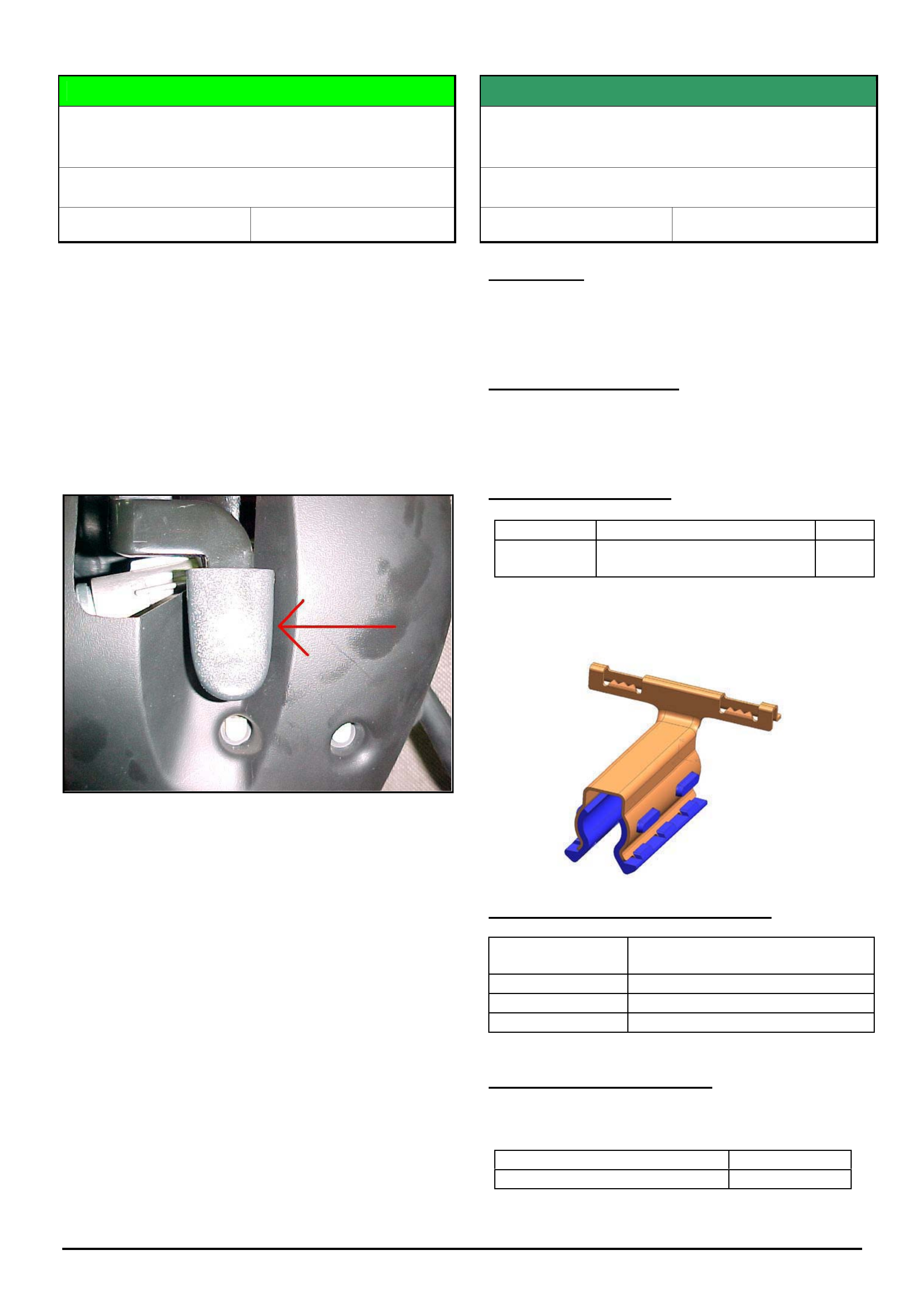
The bump stop is shown as key 2 in figure 1 below.
Figure 1.
CORRECTION – Service
1. Inspect the bump stops on both sides of the glove
compartment, to confirm whether one or both stops
are torn.
2. Remove the glove compartment following the
procedure outlined in Holden SIP Section 1A3 para
3.2, taking note to exercise particular care to avoid
damaging the glove compartment while removing
hinge pins.
3. Remove torn bump stop/s.
4. Fit new bump stops as follows:
- Fit standard bump stop (92096917) to one side of
glove compartment, and solid type bump stop
(92166561) to the other side. Figures 2 and 3
show the difference in construction of the standard
and solid bump stops
NOTE. Do not attempt to fit two of the solid type
bump stops, as the force required to fit the glove
compartment will result in damage to the glove
compartment.
5. Reinstall glovebox as follows:
- Engage lower hinge points, then rotate glove box
up into closed position whilst pushing sideways to
compress the flexible bump stop. This action is
required to provide clearance for the solid bump
stop as it wipes past the Instrument Panel structure.
NOTE: Failure to push glove box sideways as
described, may result in damage to the glovebox.
Figure 2.
Standard flexible bump
stop p/n 92096917
Figure 3.
Solid bump stop p/n
92166561
PARTS INFORMATION
Part No.: Partfinder Name Qty:
92096917 Bumper instrument panel
compartment door
(Standard)
1
92166561 Bumper instrument panel
compartment door (Solid)
1
WARRANTY CLAIM INFORMATION
Use Labour Times information in Warranty Information
section of current PV SIP CD
Update
HOLDEN SERVICE TECHLINE ________________________________________________________________________________MARCH, 2005
12
Holden Techlines are written to inform technicians of conditions that may occur on some vehicles, and to provide information that could assist in the
proper service fix of a vehicle. If a condition is described, do not assume the service fix applies to a vehicle or that the vehicle will have that condition.
SERVICE FIX
Water Enters Cabin Over Top Of Doors
VY, V2, WK
Group 1 Ref. No. TL0770 - 0502
CONDITION
During heavy rain, water may enter the cabin over the
top of door(s).
CAUSE
One possible cause for this condition is if the flocking
on the upper part of the door seal becomes saturated,
water may wick its way across the face of the seal and
into the cabin
CORRECTION - Production
Revised weatherstrips with a lip added as shown in
figure 1 have been fitted to vehicles from:
ISOVIN: Built Date:
WK - L283009
VY - L281359
V2 - L280361
21/05/2004
18/05/2004
18/05/2004
Figure 1. Shows cross section through door seal
CORRECTION – Vehicles in Service
On vehicles with the above condition, the first step in
rectification is to ensure that the door window frame is
correctly located within the body opening. If after this
first step the water leak is still present, check if the
latest design window seals are fitted. If not, then order
new seals from HSPO and install as per procedure
shown in Passenger SIP CD.
PARTS INFORMATION
Refer Partfinder for door weatherstrip assembly part
numbers. All HSPO stocks of weatherstrips are to the
revised design.
WARRANTY CLAIM INFORMATION
Use Labour Times information in Warranty Information
section of current PV SIP CD
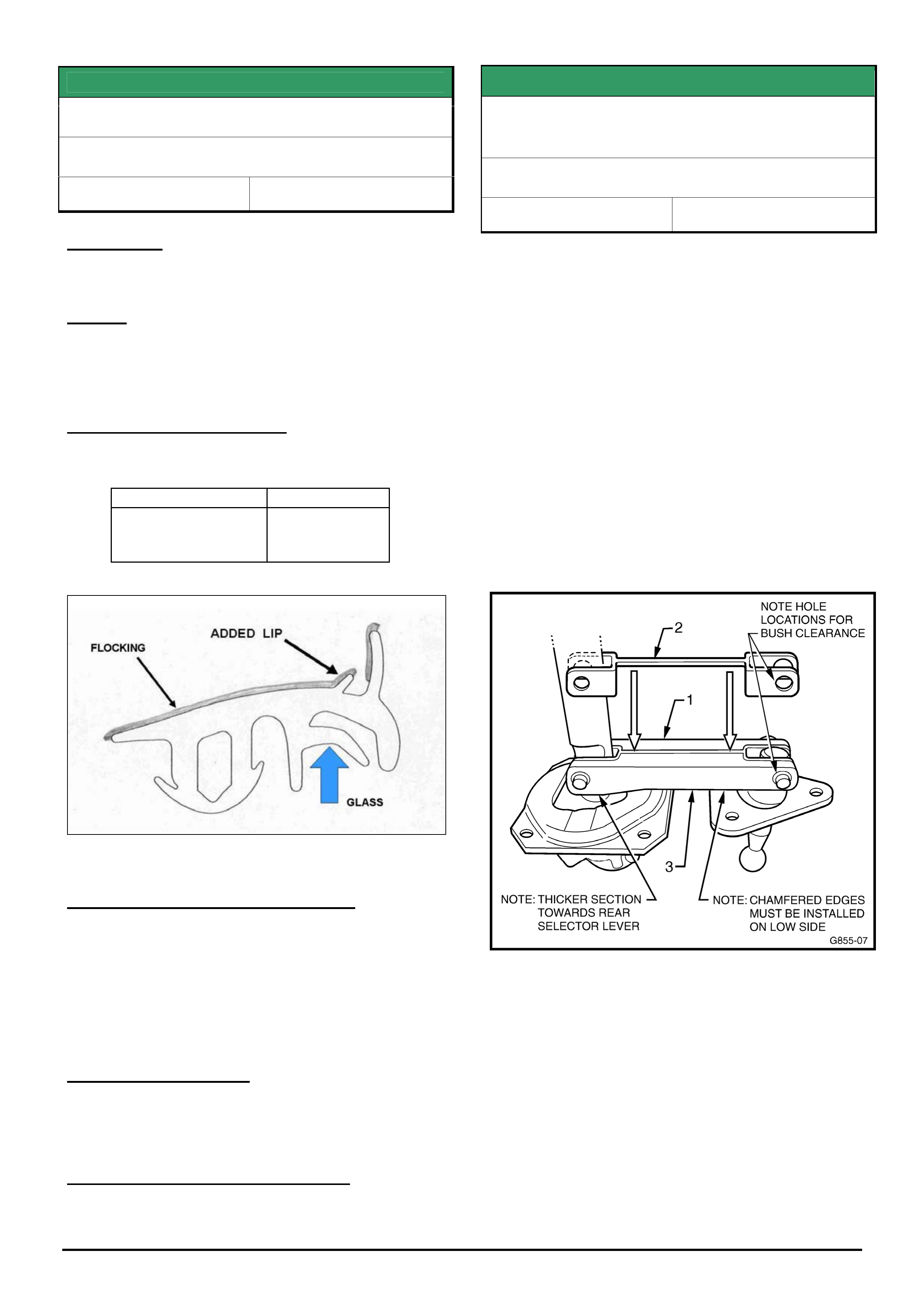
SERVICE FIX CAUTION
Hard To Select Gears After Rebuilding
Shifter Assembly
VTII, VX, VU, VY, V2, with Gen III & M/T
Group 7A Ref. No. TL0879-0502
Techline No. TL608A-0401 published in Feb. 2004
provided a procedure for rebuilding the gear shift
assembly to eliminate Shifter Linkage Rattle.
Since publishing this techline, the following issue has
been highlighted by the supplier of six speed Manual
Transmissions.
The supplier advises that on some transmissions
returned for gear selection complaints, the root cause
was the shifter assembly had been rebuilt incorrectly
by the dealer. The bridging piece (#1 in figure below)
was installed upside down and fouled on the shifter
base.
IMPORTANT: Whenever rebuilding the shifter
assembly, ensure the bridging piece/link is installed
the correct way up as shown in figure below.
NOTE: Returned transmissions that are found to have
the above condition due to incorrect repair procedure
may not be accepted for warranty.
HOLDEN SERVICE TECHLINE ________________________________________________________________________________MARCH, 2005
13
Holden Techlines are written to inform technicians of conditions that may occur on some vehicles, and to provide information that could assist in the
proper service fix of a vehicle. If a condition is described, do not assume the service fix applies to a vehicle or that the vehicle will have that condition.
SERVICE HINT
Front Windows Will Not Close Fully
VYII, V2, WK, VZ
Group 1 Ref. No. TL0745- 0502
CONDITION
On some vehicles the Front Door Windows may not
close fully which could result in windnoise and/or water
leaks.
CAUSE
Two areas which may contribute to this condition are:
1. Window glass stops set too low
2. Window seals incorrectly installed.
CORRECTION
Reset window stops and check window seal
installation as per following procedures.
1. Window glass stops set too low.
a) Loosen window stops at front and rear of window.
Refer Figure 1.
b) Operate window into fully up position. If window
will not close completely, manually push window
up into position.
c) Tighten stops.
d) If possible, allow window to remain in closed
position for 48 hours to set seals
Figure 1. Front door window stops
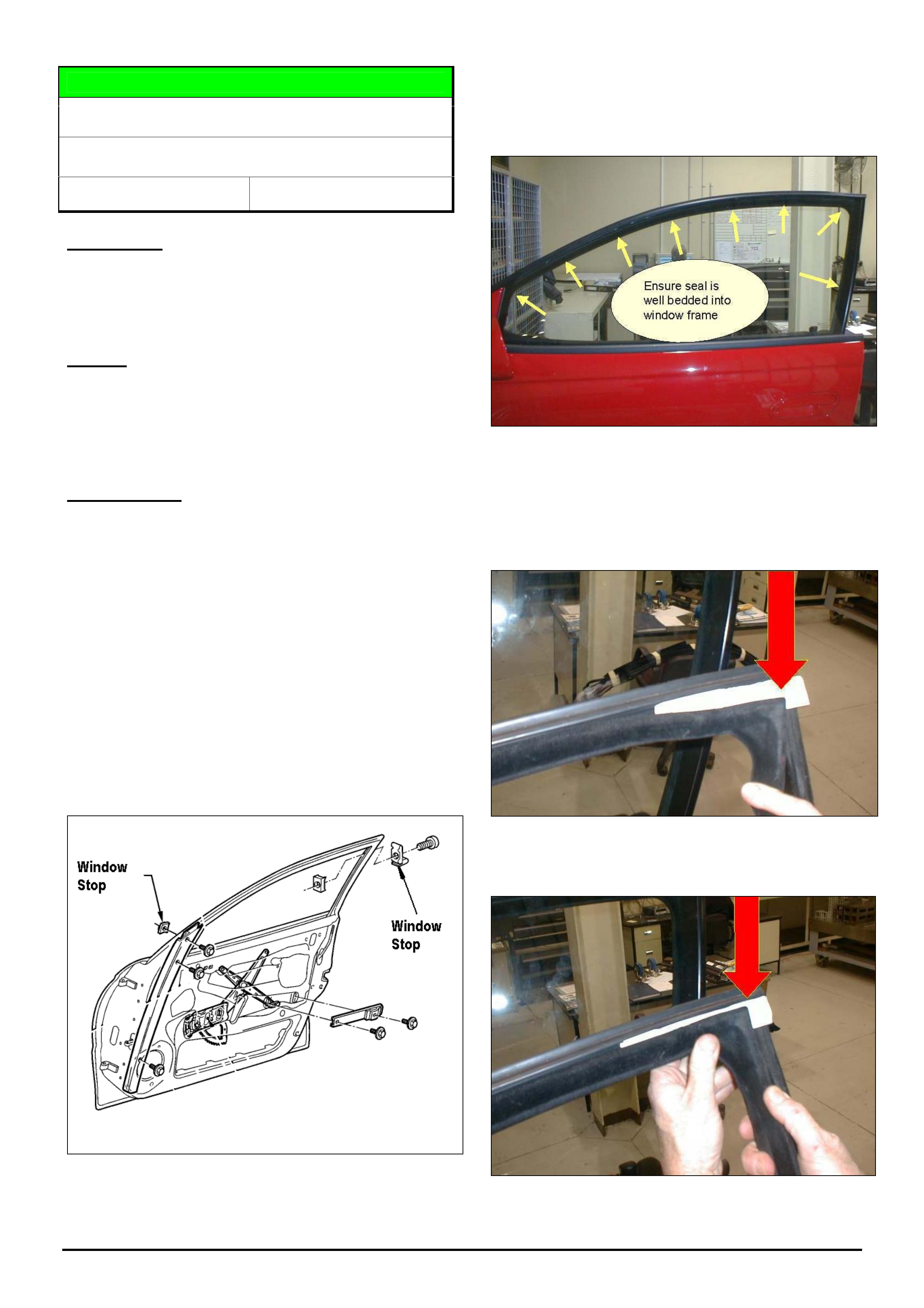
2. Window seals incorrectly installed.
a) Ensure that seals are correctly installed into the
window frames.
Figure 2.
b) Ensure that the Weather Strip Assembly rear
upper corner moulding is installed correctly. Refer
Figures 3 and 4. NOTE: the thick section of the
rear corner moulding must be located over the
corresponding depression in the doorframe.
Figure 3. Shows typical incorrect installation where
corner moulding is not fully seated into the corner of door
frame. (Paper added for clarity)
Figure 4. Corner moulding installed correctly.
HOLDEN SERVICE TECHLINE ________________________________________________________________________________MARCH, 2005
14
Holden Techlines are written to inform technicians of conditions that may occur on some vehicles, and to provide information that could assist in the
proper service fix of a vehicle. If a condition is described, do not assume the service fix applies to a vehicle or that the vehicle will have that condition.
c) Inspect window seals to ensure that they are not
damaged or twisted out of shape. If seals are
damaged or badly twisted they should be
replaced.
e) If replacing the Weather Strip Assembly – “Front
Side Door Window Upper”, drive the window up
into the Moulding and ensure that there is between
2mm and 4mm coverage of the window by the
moulding. Cycle the window up and down a
number of times to ensure that the seals are well
bedded into the door frame.
f) If possible, allow window to remain in closed
position for 48 hours to set seals
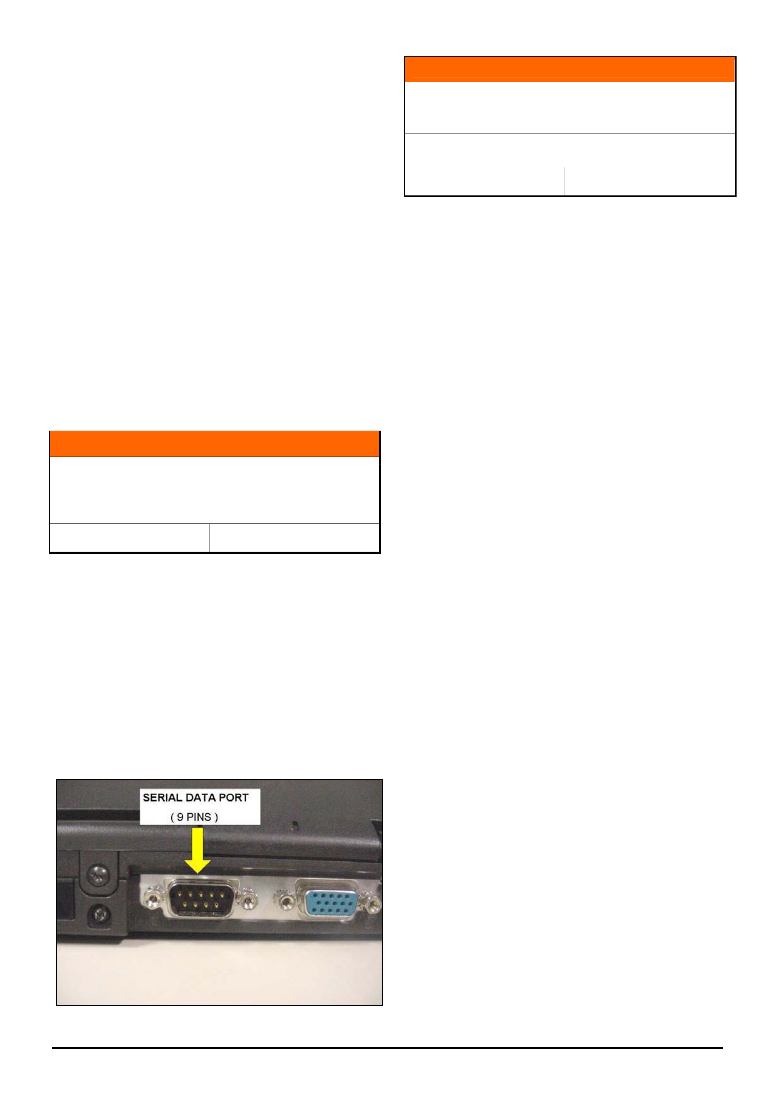
INFORMATION
PC Serial Data Ports
All
Group OB Ref. No. TL0864 - 0502
Dealers planning to purchase a new pc or lap top,
must ensure that it has a serial data port. This is the
port which the RS 232 cable used for updating Tech 2
plugs into.
Some Dealers have purchased computers without
serial data ports on the assumption they could use a
serial data to USB adaptor, only to find that they do not
work!
Tech 2 can only be updated via the RS232 cable from
a serial data port, not a USB port.
INFORMATION
Release of Dexron III (“H” Revision)
Automatic Transmission Fluid (ATF)
All models with A/T
Group 7B Ref. No. TL0860- 0502
General Motors DEXRON III ATF specification has
been upgraded to DEXRON III (H-Revision).
Commercially available fluids labelled as “DEXRON III,
Approved for the H Specification”, can be used in any
transmission application which specifies the use of
DEXRON III, IIE, II or DEXRON.
Current stock of DEXRON III ATF can be used until
the supply is depleted.
HOLDEN SERVICE TECHLINE ________________________________________________________________________________MARCH, 2005
15
Holden Techlines are written to inform technicians of conditions that may occur on some vehicles, and to provide information that could assist in the
proper service fix of a vehicle. If a condition is described, do not assume the service fix applies to a vehicle or that the vehicle will have that condition.
SERVICE FIX
Rear Axle “Cyclic Knock” .
All V & W with IRS (non LSD)
Group 4 Ref. No. TL0602A- 0502
This Techline supercedes the previous one in Issue
11, Dec. 2004. It is revised by modifying the service
correction procedure and breakpoint information.
CONDITION
Cyclic knock noise which may occur when coasting in
speed range between 70-40km/hr whilst driving in a
straight line.
This condition is confirmed if the cyclic knock noise
disappears when the vehicle is driven in a slalom
motion.
CAUSE
Excessive axial float of the inner axle shafts within the
differential.
Problem affects V and W models (non LSD) with the
exception of cab-chassis and crew-cab vehicles (beam
axle).
CORRECTION – Production
Revised rear axle assemblies with reduced clearance
circlip grooves in the inner axle shafts were phased
into vehicle production over the last 2 weeks of Sep
2004 commencing from vehicle:
ISOVIN: Built Date:
**********L334258 16/09/2004
CORRECTION – Service
Summary: After verifying that vehicle has symptoms
as described above, proceed as follows: THIS
PROCEDURE WILL REQUIRE THE VEHICLE TO BE
LEFT IN DEALERSHIP OVERNIGHT.
Procedure.
1. Contact Dana via their website to register a case
of “cyclic knock”.
Once case is approved, Dana will send a set of
differential inner-axle assemblies with “upper
spec. spline” and reduced clearance circlip
grooves for the complaint vehicle.
2. Remove LHS and RHS driveshafts.
NOTE: mark the inner CV joints of both
driveshafts before completely removing from the
vehicle.
(Refer SIP Section 4B, 2.7 "Driveshaft Assembly”)
3. Remove LHS and RHS inner-axles from
differential.
(Refer SIP Section 4B, 2.9 "Inner Axle Shaft Seal".
Note: Diff does not need to be removed from
vehicle.)
4. Remove circlip from each inner-axle.
5. Install circlips to the new shafts supplied by Dana.
6. Clean all traces of oil from splines of the new
shafts and the matching splines in the differential.
Follow the pre-application cleaning instructions
provided on the Loctite 609 package.
7. Apply Loctite 609 to the splines on the shafts
before reassembling shafts into differential.
8. Allow Loctite to cure for 6 hours minimum before
proceeding.
9. Reverse both driveshafts before reinstalling. This
means reinstalling driveshafts with the inner CV
joint now on the outside.
WARRANTY CLAIM INFORMATION
For vehicles covered under warranty use the following
information.
Description Diff Cyclic knock noise
reduction procedure
Labour Op. No. F000200
Time 1.8 hr
Failure Code F0040 noisy
Update
HOLDEN SERVICE TECHLINE ________________________________________________________________________________MARCH, 2005
17
Holden Techlines are written to inform technicians of conditions that may occur on some vehicles, and to provide information that could assist in the
proper service fix of a vehicle. If a condition is described, do not assume the service fix applies to a vehicle or that the vehicle will have that condition.
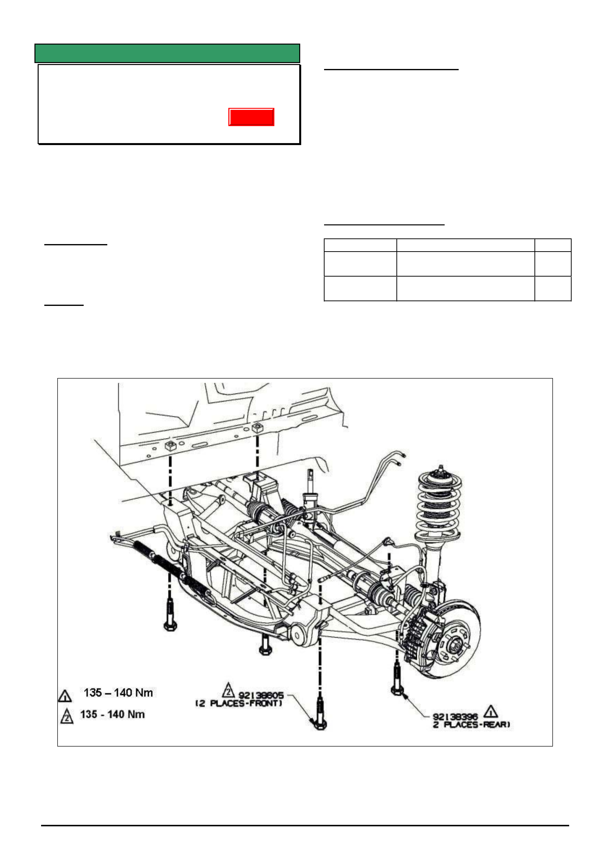
SERVICE FIX
Front Suspension Clunk (Front Subframe)
VY & VZ Adventra
GROUP 3 TL0718A-0502
This Techline supercedes the previous one in Issue 6,
July, 2004. It is revised by changing all 4 subframe
mounting bolt toques to the same value.
Also refer to Techline TL0638-0403 published in Issue
3, 2004. which gives another possible cause for front
suspension clunk
CONDITION
Loud metallic clunk noise from front suspension
usually heard when driving over pot holes or braking
over speedhumps .
CAUSE
One possible cause for this condition is fore-aft
movement of the front subframe relative to the body
due to insufficient clamp load at the attaching points.
CORRECTION – Service
On any vehicle with the symptoms as described,
ensure that all 4 subframe mounting bolts are
tightened to 135 -140 Nm.
NOTE: As these bolts are being tightened only and
not removed they do not need replacing.
If they are removed for any reason then they should be
replaced as per the standard practice for micro-
encapsulated fasteners.
PARTS INFORMATION
Part No.: Description: Qty
92138605 Bolt Front suspension
frame - front
2
92138396 Bolt Front suspension
frame - rear
2
Update
HOLDEN SERVICE TECHLINE ________________________________________________________________________________MARCH, 2005
18
Holden Techlines are written to inform technicians of conditions that may occur on some vehicles, and to provide information that could assist in the
proper service fix of a vehicle. If a condition is described, do not assume the service fix applies to a vehicle or that the vehicle will have that condition.
SERVICE PROCEDURE
Occupant Climate Control Blows Hot Air
VY, V2 II & III, WK and VZ (with OCC)
Group 2 Ref. No. TL0851- 0502
CONDITION
One or more of the following conditions may occur
intermittently:
• A/C blows hot air when cool air is selected.
• A/C blows hot air and changes mode to feet.
• ‘X ‘ appears on the OCC display
• Code 15 stored in the OCC module.
• In car temp. sensor reads –40° on Tech II.
CAUSE
A poor connection inside the in-car temperature
sensor causes an open circuit.
CORRECTION – Production
Production process for the manufacture of in-car
temperature sensors has been improved for vehicles
from:
ISOVIN: Built Date:
L405066 21/02/05
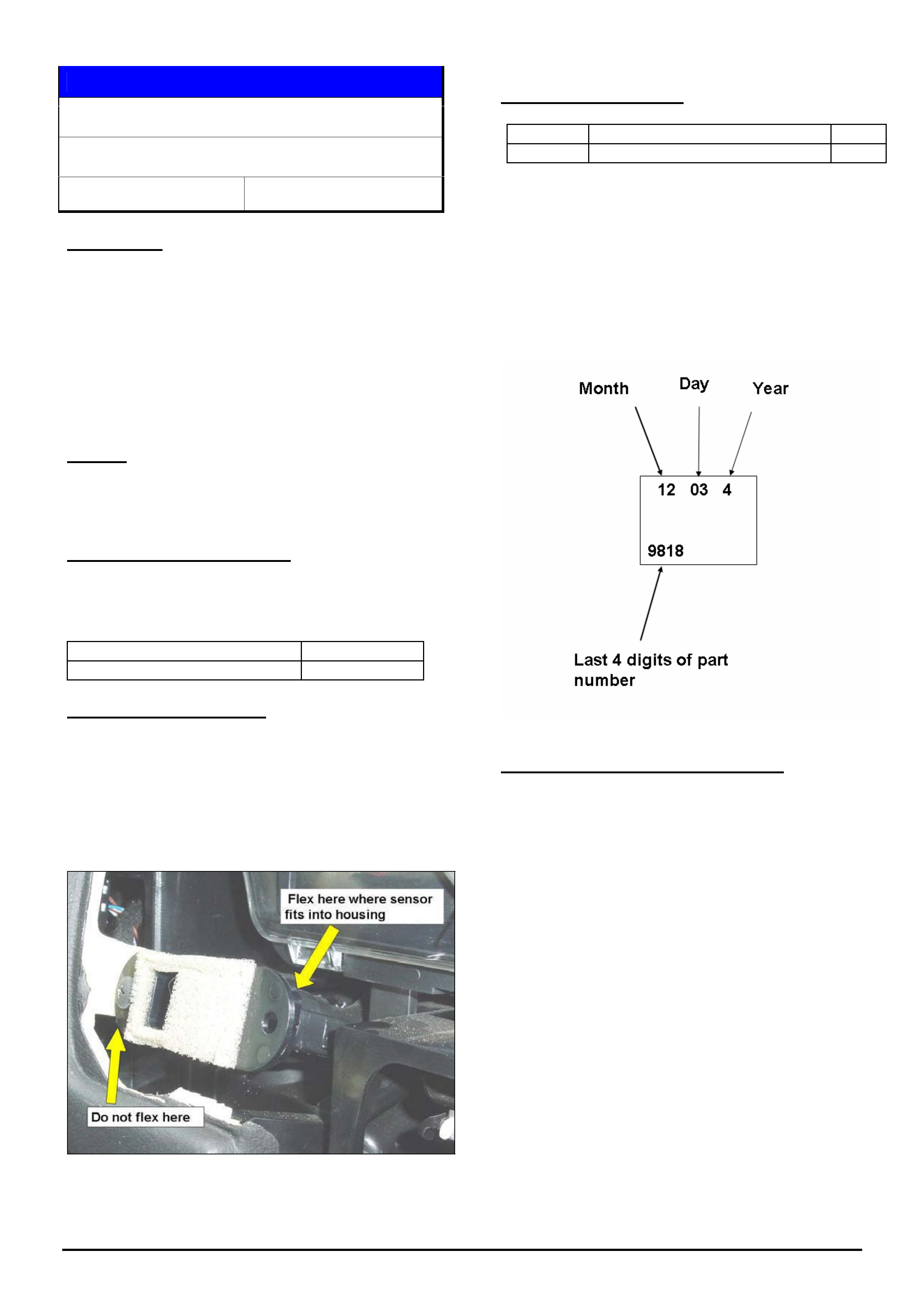
CORRECTION – Service
Perform normal SIP diagnosis.
Hint.
View the in-car temperature sensor reading on TECH
II while flexing the sensor body at the connector to
help identify an intermittently faulting sensor. Refer
Figure 1.
Figure 1. Shows in car temperature sensor
Replace the in-car temperature sensor if diagnosis
confirms it as faulty.
PARTS INFORMATION
Part No.: Partfinder Name Qty:
16229818 Sensor Asm. – Inside Air Temp. 1
All HSPO stock has been cleansed of suspect faulty
sensors.
The date code breakpoint for certified stock is 12- 03 -
4 (manufactured Dec. 3rd, 2004).
The break point can be checked by inspecting the
label on the part as follows.
WARRANTY CLAIM INFORMATION
Use existing warranty information in SIP.
HOLDEN SERVICE TECHLINE ________________________________________________________________________________MARCH, 2005
19
Holden Techlines are written to inform technicians of conditions that may occur on some vehicles, and to provide information that could assist in the
proper service fix of a vehicle. If a condition is described, do not assume the service fix applies to a vehicle or that the vehicle will have that condition.
INFORMATION
Power Steering Shudder Service Fix
Hose Contamination
VY WK with V6 engine
Group 9 Ref. No. TL0880- 0502
A contamination issue affecting some of the power
steering shudder service fix hoses was recently
identified and has now been rectified.
The contamination occurred during the hose
production process.
SERVICE ACTION
Dealers should confirm that any service fix hose to
be fitted to a vehicle is post breakpoint.
Breakpoint:
All hoses manufactured from 11 Feb 05. date code
(11B5).
All hoses supplied by HSPO warehouse from 11 Feb
05 are certified parts.
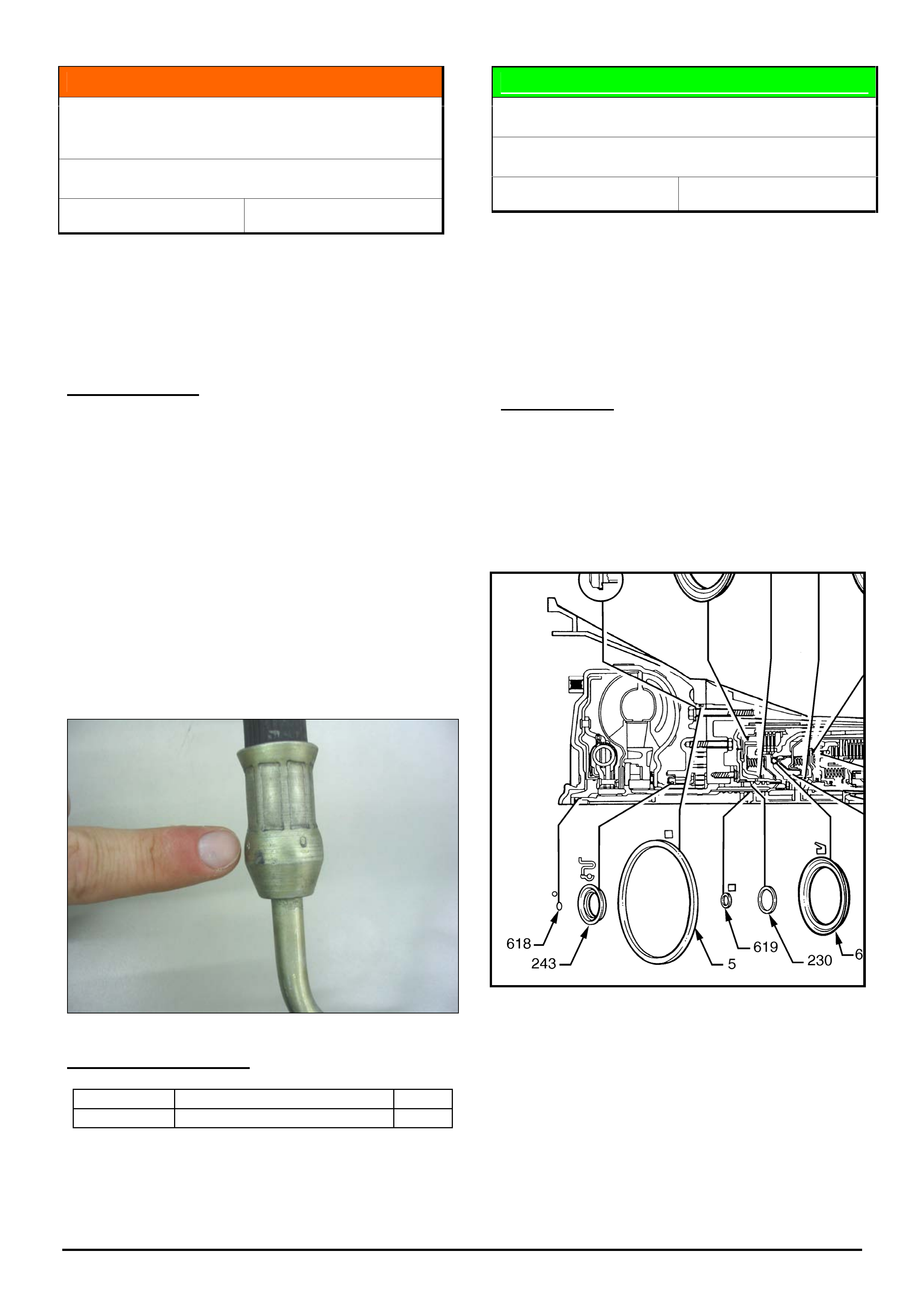
The manufacturing date code is stamped around the
metal ferrule where the hose is attached.
Date Code Explanation.
For example 11B5, 11 being the day of the month, B
being the month of the year, ie Jan = A, Feb = B, Mar
= C etc, and 5 represents the year of the decade, ie
2005.
PARTS INFORMATION
Part No.: Partfinder Name Qty:
92174786 Power Steering Hose 1
NOTE: Pre breakpoint hoses that are fitted to
vehicles do not need to be replaced with post
breakpoint hose.
DIAGNOSTIC HINT
Transmission Slip Codes P0894, P1870
VY, VZ, WK, WL & 4L60E A/T
Group 7B Ref. No. TL0848 - 0502
The codes P0894 (VZ, WL) or P1870 (VY, WK) may
be logged causing the “check engine light“ to come
on.
Recent tear down analysis of transmissions replaced
for P0894 and P1870, reveals some instances where
the o-ring seal on the turbine shaft was either
missing or damaged. (refer Figure 1 item #618)
SERVICE HINT.
On any vehicle with the above symptoms, DO NOT
replace the transmission without first performing the
normal fault code diagnosis as per SIP. Pay
particular attention to the step which says to “check
the input shaft and housing assembly for
cut/damaged turbine shaft o-ring seal”.
Figure 1.
HOLDEN SERVICE TECHLINE ________________________________________________________________________________MARCH, 2005
20
Holden Techlines are written to inform technicians of conditions that may occur on some vehicles, and to provide information that could assist in the
proper service fix of a vehicle. If a condition is described, do not assume the service fix applies to a vehicle or that the vehicle will have that condition.
SERVICE FI
X
Ignition Key Jams In Off Position – Or Is
Difficult To Turn From Off Position
TS, TT, XC Barina/Combo with “S”
Profile Ignition Keys/Barrels
Group 9 Ref. No. TL421B - 0502
This Techline supercedes the previous one in Issue
3, Mar. 2003. It is revised by adding a service hint
on how to freeup a jammed ignition lock.
PROBLEM DESCRIPTION
In some vehicles the ignition key may jam in the
“OFF” position or be difficult to turn from the “OFF”
position.
This condition only affects ignition barrels/keys with
“S” profile. It does not affect those with “D” profile.
To confirm profile type refer to Part Finder TS
Catalogue, section 06-250A.
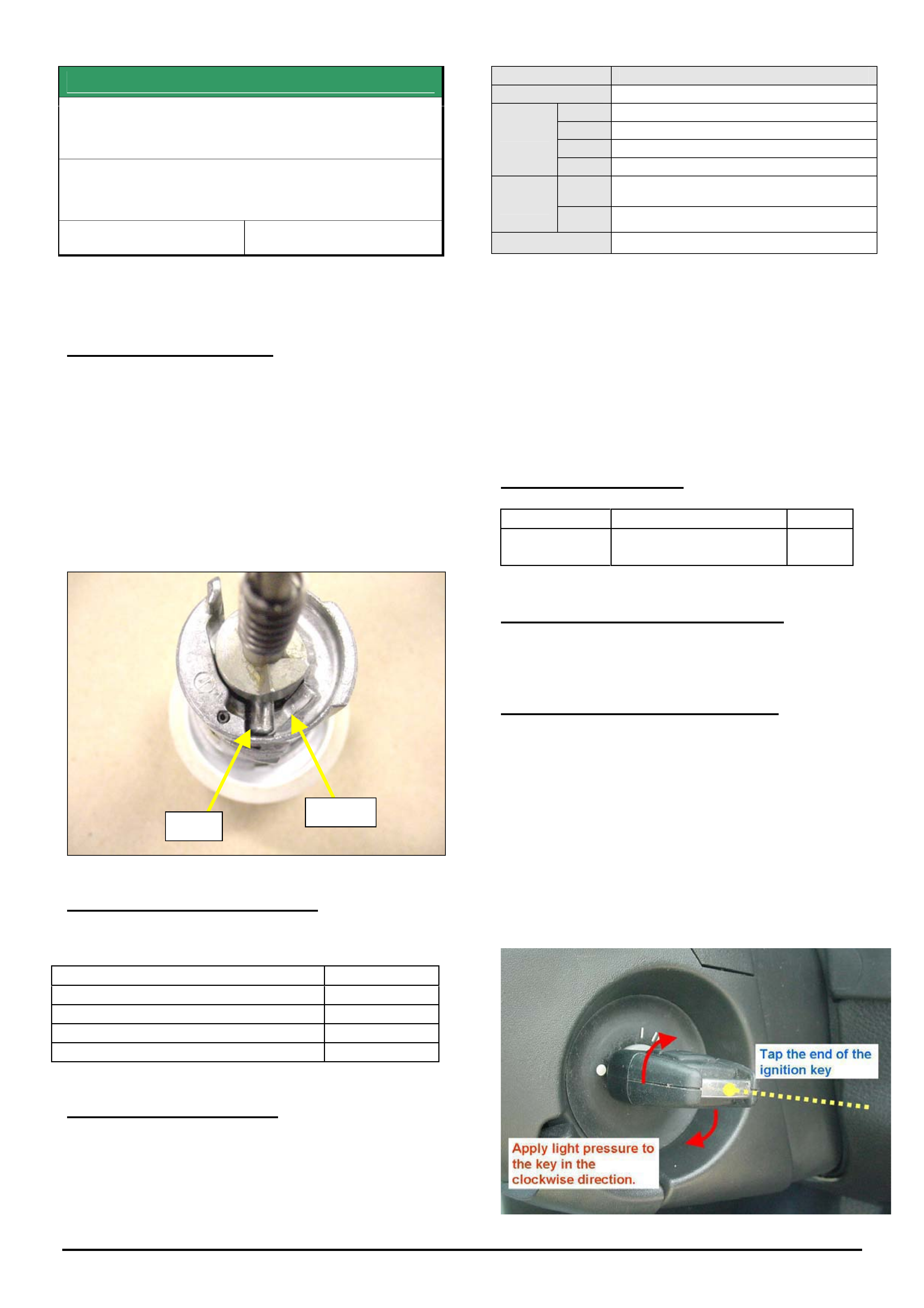
This condition results from the hard barrel pin
causing excessive wear of the soft alloy ramp section
of the barrel housing. Refer Figure 1.
PIN RAMP
Figure 1.
PRODUCTION RECTIFICATION
Revised ignition barrels have been fitted to vehicles
from the following breakpoints:
ISOVIN: Build Date:
XC Barina - W0L0XCF6824246086 30/04/02
XC Combo - W0L0XCF2523030966 30/04/02
TS Astra - W0L0TGF4825195733 May 02
TT Zafira - W0L0TGF752H035990 Aug 02
SERVICE RECTIFICATION
Summary: For complaint vehicles install a new
ignition lock cylinder and tumblers.
To Remove and Reinstall the ignition lock cylinder
refer to procedure in TIS 2000 found as follows:
TIS Screen Ð Select the following Ð
Service Information Standard Information
Model Astra G/Corsa C/Zafira
Year 2002
Eng. -
Vehicle
Data
Trans. -
Asm.
Group
- Electrical Equipment & Instruments
+Switches, Control Units, Relays, Ign Lock
Standard
Info. Applic’n Repair (Remove,Install,Adjust)
Document List Lock Cylinder for strg. & ign. lock R & R
Tumbler Replacement
The old tumblers must be replaced with the new
ones supplied in the kit. To retain the same key
coding, remove the tumblers one at a time from the
old lock shaft, read the number stamped on the
tumbler and then install a new tumbler with the same
code into the new lock shaft in the equivalent slot.
Note. There are 4 different codes of tumbler and a
total of 10 tumblers per lock cylinder.
PARTS INFORMATION
Part No.: Description: Qty:
92146450 Barrel Kit – Ignition (S
profile)
1
WARRANTY CLAIM INFORMATION
Use Labour Times information in Warranty
Information section of current PV SIP CD
Hint For Freeing Up Jammed Lock
The following method may help to rotate the jammed
ignition lock preventing the need to tow a vehicle or
assist when replacing the ignition barrel assembly.
1. Apply light clockwise pressure to the key while
fitted in the ignition lock.
2. With clockwise pressure still applied, lightly tap
the end of the ignition key with a small nylon
hammer.
CAUTION: DO NOT DAMAGE THE KEY HEAD
HOLDEN SERVICE TECHLINE ________________________________________________________________________________APRIL, 2005
5
Holden Techlines are written to inform technicians of conditions that may occur on some vehicles, and to provide information that could assist in the
proper service fix of a vehicle. If a condition is described, do not assume the service fix applies to a vehicle or that the vehicle will have that condition.
SERVICE FIX
Door Check Link Attaching Bolt(s) Loose
AH Astra
Group 1 Ref. No. TL0895- 0503
CONDITION
On some vehicles one or more of the door check link
attaching bolts may loosen in service.
CORRECTION – Production
Door check link bolt torques increased to 27 (+2/-1)
Nm on vehicles from:
ISOVIN: Built Date:
W0L0AHL4855006365 23/08/2004
CORRECTION – Service
On any vehicle where a door check link attaching bolt
comes loose, remove all door checklink bolts, apply a
thread locking compound to threads then retighten
bolts to 27 Nm.
WARRANTY CLAIM INFORMATION
Use Labour Times information in Warranty Information
section of current PV SIP CD
INFORMATION
Oil Pan Sealant Availability and Usage
HFV6 Engine
Group 6A Ref. No. TL0888 - 0503
CONDITION
The current Passenger SIP CD specifies RTV sealant
p/n 12574611 for HFV6 engine oil pan replacement.
Unfortunately, because this sealant is not available
locally, there has been confusion over what sealant to
use in its place.
CORRECTION – Service
The sealant to be used for HFV6 engine oil pan
replacement procedures is p/n 92144969.
Future versions of Passenger SIP will be revised to
show p/n 92144969 as the replacement for 12574611.
PARTFINDER INFORMATION
PartFinder does not currently list any sealant part
number for the engine oil pan . Future versions of
PartFinder will show p/n 92144969 as the required
sealant for this application.
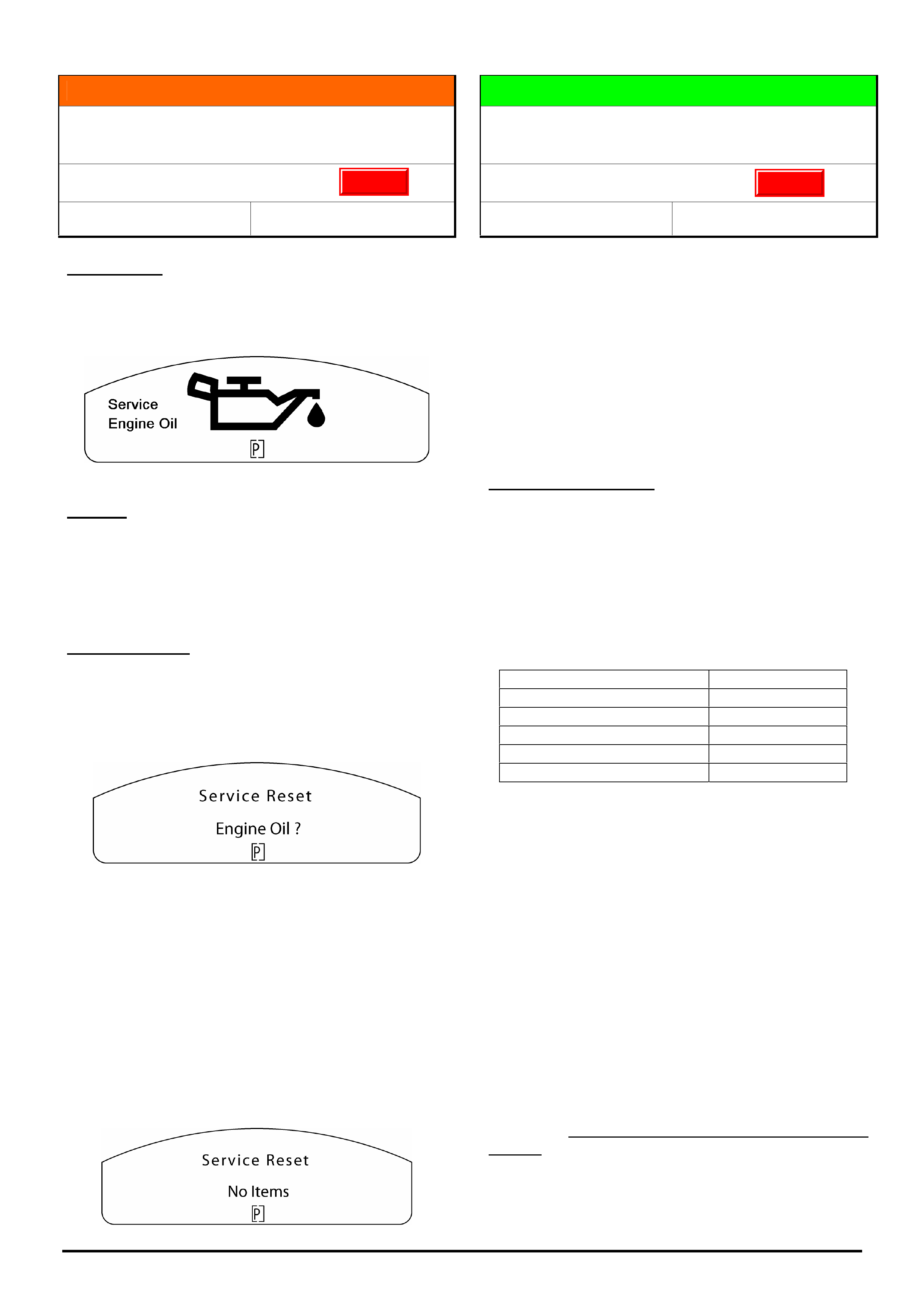
HOLDEN SERVICE TECHLINE ________________________________________________________________________________APRIL, 2005
6
Holden Techlines are written to inform technicians of conditions that may occur on some vehicles, and to provide information that could assist in the
proper service fix of a vehicle. If a condition is described, do not assume the service fix applies to a vehicle or that the vehicle will have that condition.
INFORMATION
Service Engine Oil Warning Displays in the
Instrument Cluster.
VZ, WL
Group 12 Ref. No. TL0890- 0503
CONDITION
On some vehicles the “Service Engine Oil” warning
icon may display in the instrument cluster when the
ignition is cycled.
CAUSE
The “Service Engine Oil” feature is not available for the
local market and has been inadvertantly enabled in the
engine calibration.
If the above warning icon displays, the following reset
procedure must be performed.
Reset procedure
1. Press and hold the up and down buttons on the
trip computer mode switch while turning the ignition
key on until a beep is heard, the following will be
displayed.
2. Press the set button on the trip computer mode
switch until a beep is heard (approx 8-10 seconds) to
reset the service item.
The display will then revert back to the start up
sequence.
If more than one service items are set, the next
service item will be displayed.
Press the set button on the trip computer mode
switch to reset the next service item if required.
3. The following will then be displayed.
DIAGNOSIS HINT
Steering Wheel Radio Remote Control
Switches Function Incorrectly
VY, WL, V2 Series II & III
Group 12 Ref. No. TL0889- 0503
Blaupunkt receive a large number of requests for
changeover radios due to customers and dealers
experiencing the incorrect function when the steering
wheel remote buttons are depressed.
The majority of these complaints are not due to a fault
with the radio. Therefore, to avoid incorrect diagnosis,
perform the following checks. These checks are
designed to determine if there is a poor connection
between the remote control switches and the radio
causing a high resistance which results in the incorrect
function.
Checking Procedure
1. Remove the radio. Use a multi meter to measure
the resistance between terminals C11 & C12 in the X1
connector; when no buttons are depressed the
resistance should be approximately 3674 ohms.
2. When each of the following switches are
depressed the resistance measured should be
approximately as listed below.
Next up button 794 ohms
Mute button 284 ohms
Next down button 464 ohms
Volume up button 164 ohms
Mode button 1474 ohms
Volume down button 82 ohms
3. If a high resistance is detected, disconnect all
connections, inspect for damage or corrosion,
reconnect and measure the resistance again. If the
resistance has changed and the correct function of the
radio remote switches is achieved then the problem is
considered to be connection related.
4. If the fault is still present, use the wiring diagrams,
check each section of the circuit separately (wiring
harness, clock spring, radio remote switches) to allow
diagnosis of the faulty component. .
Note: When measuring the resistance of this circuit,
ensure that any probing does not deform the terminals
in vehicle harness.
If the fault still persists after performing the above
diagnosis, contact Blaupunkt for additional diagnosis
assistance and advise that you have completed these
checks.
Update
Update

HOLDEN SERVICE TECHLINE ________________________________________________________________________________APRIL, 2005
7
Holden Techlines are written to inform technicians of conditions that may occur on some vehicles, and to provide information that could assist in the
proper service fix of a vehicle. If a condition is described, do not assume the service fix applies to a vehicle or that the vehicle will have that condition.
INFORMATION
Tis 2000 and Tech 2 ECU Programming
Terminology
GROUP OB TL0902-0503
When trying to reset or program modules with TIS
2000 or Tech 2, “reset ECU” or “program ECU” is often
displayed. Many Dealers assume ECU stands for
Engine Control Unit. This techline is to clarify that
ECU stands for “Electronic control unit” not “engine
control unit” and therefore applies to the module you
are dealing with.
For example - If you are resetting a CIM and tech 2
displays “reset ECU” it is referring to the CIM because
that is the module you are resetting and have
accessed with tech 2.
DIAGNOSIS HINT
Programming New (Replacement)
Transmission Electronic Control Units (TCM)
VZ, WL V6 and Opel Vehicles
Group 7B Ref. No. TL0899-0503
CONDITION
Some dealers report multiple DTC’s set and no Tech 2
communication after replacing Transmission Control
Module (TCM).
CAUSE
Service replacement TCM’s are blank and require
programming via SPS (Service Programming System)
similar to engine ECU’s.
CORRECTION
After fitting a new TCM, it must be programmed via
SPS procedure which can be found in Passenger SIP
as follows:
Introduction and Tech 2 / Section 0C-Tech 2 /
Service Programming System (SPS) / SPS Process
NOTE: When you are programming a TCM and Tech 2
displays “program ECU” it is referring to the TCM not
the Engine Control Unit.
After the software download is completed clear any
stored DTC’s .
Recheck for any DTC’s.
DIAGNOSIS HINT
Cruise Control Not Working
ZC Vectra, AH Astra Manual Trans. Only
Group 6C Ref. No. TL0900-0503
CONDITION
Customer complains that Cruise Control intermittently
wont engage. Dealer cannot reproduce fault and no
related trouble codes are stored.
The above condition will occur if the driver starts the
engine and commences driving from rest without
initially depressing the brake pedal.
The engine ECU must see a valid active brake switch
input before it allows cruise control to function.
This situation is more likely to happen on a highway or
other similar open flat roads where starting and driving
off does not require use of the brake pedal.
This condition will not occur on a vehicle fitted with an
automatic transmission as the brake pedal must be
depressed in order to shift the T-bar out of Park.
Please explain to the driver -
The cruise control cannot be activated until the foot
brake has been operated at least once after the
ignition has been turned on.
This requirement is also explained in the Owner’s
Handbook.
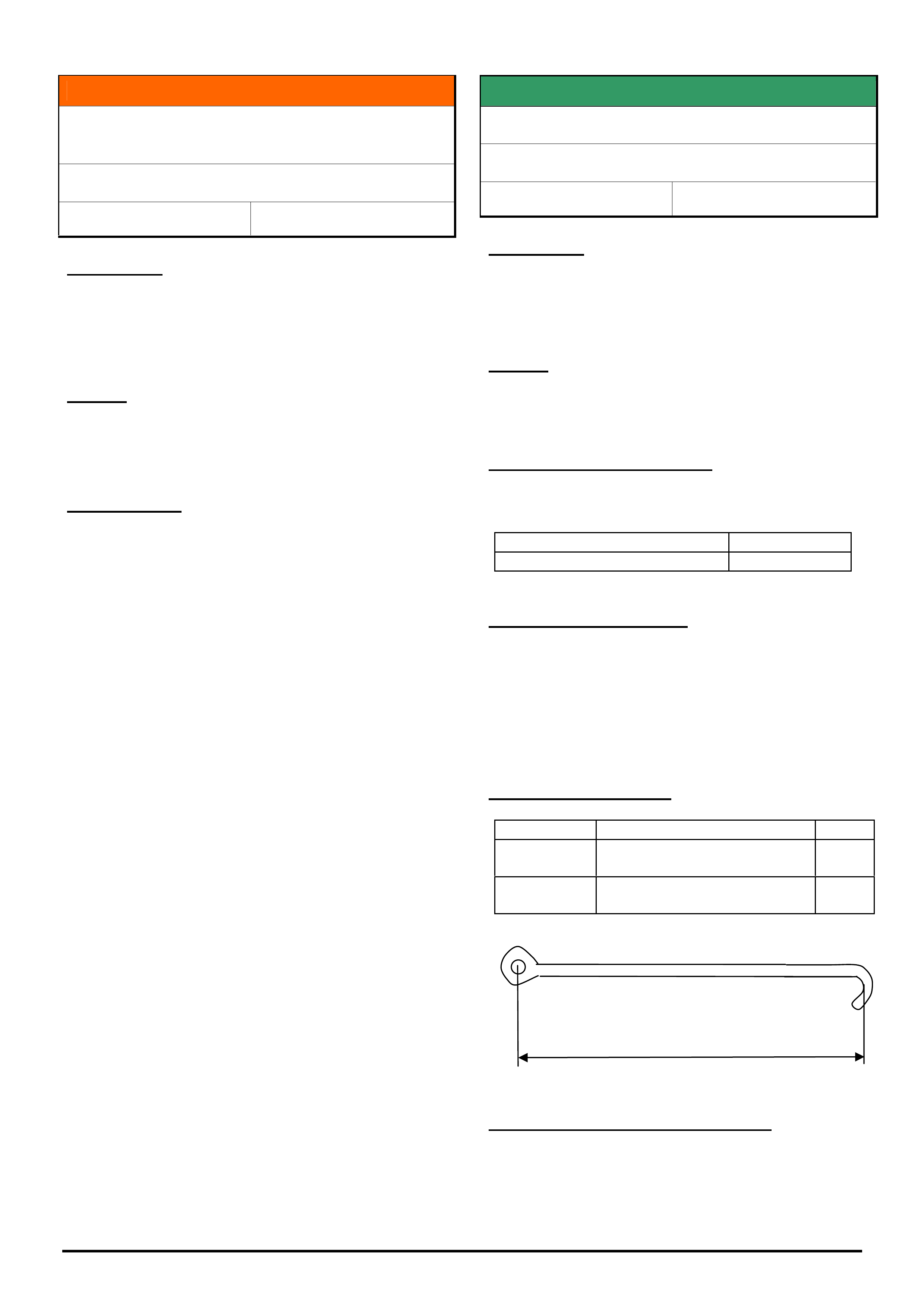
HOLDEN SERVICE TECHLINE ________________________________________________________________________________APRIL, 2005
8
Holden Techlines are written to inform technicians of conditions that may occur on some vehicles, and to provide information that could assist in the
proper service fix of a vehicle. If a condition is described, do not assume the service fix applies to a vehicle or that the vehicle will have that condition.
INFORMATION
TIS 2000 Security Access and SPS Issues Due
To Hardware Key Incompatibility With New PC
All Models
Group OB Ref. No. TL0896- 0503
CONDITION
After installation of a new PC, Dealers may report
problems accessing security information or service
programming system (SPS). An error message may
appear. The problem may be intermittent.
CAUSE
New PC’s with a processor speed which is 2.0 Ghz or
greater are not compatible with older style “dongle”
hardware keys.
CORRECTION
To overcome this, a new “superpro” hardware key kit
(Parallel or USB) will need to be purchased through
SPX.
Please note: New hardware keys will need to be
registered before they will work.
The above information was explained in All Dealer
Letter 14/04
SERVICE FIX
Endgate Touches Rear Bumper Facia
VY and VZ Crewman
Group 1 Ref. No. TL0784 - 0503
CONDITION
On some vehicles the endgate may touch the rear
bumper facia when opened. In some cases paint
damage may occur.
CAUSE
Insufficient clearance between bumper facia and
endgate when opened.
CORRECTION – Production
Revised endgate cables (15 mm shorter) were
introduced into vehicle production from:
ISOVIN: Built Date:
**********L413997 22/3/05
CORRECTION – Service
On vehicles with the above condition, fit new endgate
cables 92183896 which are 15mm shorter than the
previous cable 92110192.
Refer Passenger SIP CD for cable replacement
procedure.
PARTS INFORMATION
Part No.: Partfinder Name Qty:
92183896 Cable assembly endgate
(cable length – 495 mm)
2
92110192 Cable assembly endgate
(cable length – 510 mm)
2
WARRANTY CLAIM INFORMATION
Use Labour Times information in Warranty Information
section of current PV SIP CD
Cable Length
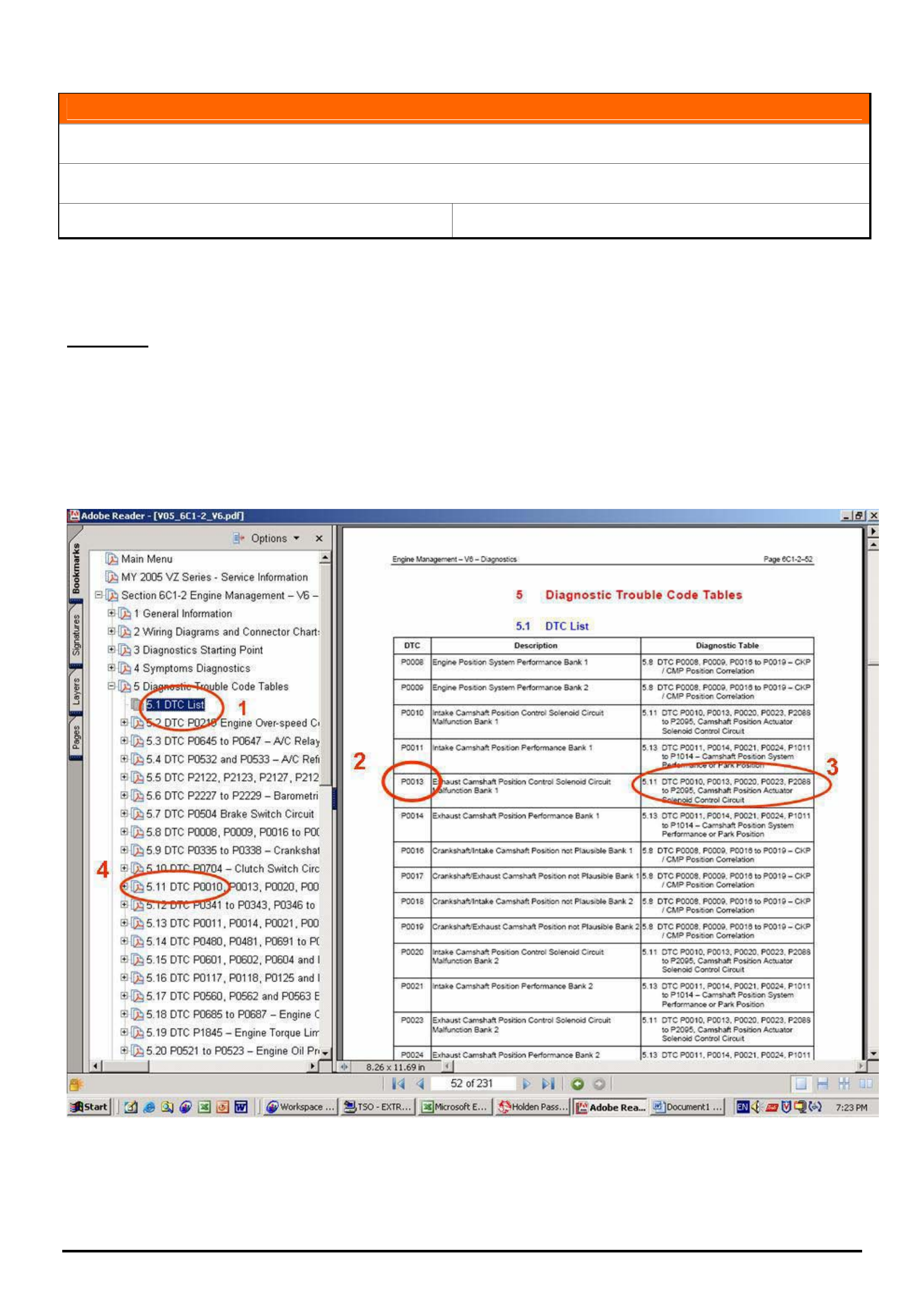
HOLDEN SERVICE TECHLINE ________________________________________________________________________________APRIL, 2005
9
Holden Techlines are written to inform technicians of conditions that may occur on some vehicles, and to provide information that could assist in the
proper service fix of a vehicle. If a condition is described, do not assume the service fix applies to a vehicle or that the vehicle will have that condition.
INFORMATION
Finding Engine Diagnostic Trouble Codes (DTC’s) in SIP
VZ, WL V6 and V8
Group 6C Ref. No. TL0898- 0503
With the introduction of VZ / WL, finding engine related diagnostic trouble codes (DTC’s) in SIP has changed slightly
from previous models. The DTC’s are no longer in numerical order in the left hand menu. Refer picture below.
The revised procedure is shown below.
Procedure.
In SIP, select VZ/WL Service Information, V6 Engine, then Section 6C1-2 Engine Management V6 Diagnostics or
for Gen III V8, select Section 6C3-2 Powertrain Management Diagnostics.
Select Diagnostic Trouble Code Tables, then DTC list. (Refer # 1 below). From the main page find your DTC in the
lefthand column (refer # 2) together with the DTC description. In the right hand column is the DTC List reference
number and other related DTC’s (refer # 3).
From the menu on the lefthand side, select the reference number in the DTC List, (refer # 4). In here you will find the
DTC description, circuit diagram, additional information and the diagnostic procedure.
HOLDEN SERVICE TECHLINE ________________________________________________________________________________APRIL, 2005
12
Holden Techlines are written to inform technicians of conditions that may occur on some vehicles, and to provide information that could assist in the
proper service fix of a vehicle. If a condition is described, do not assume the service fix applies to a vehicle or that the vehicle will have that condition.
SERVICE PROCEDURE
Mandatory Receiver Dryer Replacement With
Compressor Replacement
TS Astra
Group 2 Ref. No. TL0885- 0503
The receiver dryer must be replaced whenever an
A/C compressor is replaced for internal failure.
If this is not done, it is most likely that there will be a
repeat failure of the A/C compressor.
The reason is the receiver dryer becomes blocked
with debris after a compressor failure. As the
pressure sensor is in the top of receiver dryer, it will
not read true system pressure due to the blockage.
The receiver dryer must be replaced whenever an
A/C compressor is replaced for internal failure.
SERVICE FIX
Ignition Coil Failure
VZ, WL – HFV6 engine
Group 6Y Ref. No. TL0893 - 0503
CONDITION
Failed ignition coil.
CORRECTION
On any vehicle that experiences a failed ignition coil,
proceed as follows.
1. Replace failed coil as per SIP.
Ensure that replacement coil does not have a
Manufacture date between 8th May 2004 and 10th
May 2004 (inclusive). Refer to picture for
Manufacture date stamp location. Date layout is
Year-Month-Day
2. Check the manufacture date on remaining
coils. Replace any coil if date is 04-05-08 or 04-05-09
or 04-05-10
PARTS INFORMATION
Part No.: Partfinder Name Qty:
12583514 Ignition coil 1
Attention Parts Managers:
Any new coils in stock which are identified as being
manufactured on the 8th, 9th or 10th May 2004
should be returned to HSPO via CRRM. Refer to
Parts News Letter issued by HSPO.
WARRANTY INFORMATION
Use Labour Times information in Warranty
Information section of current PV SIP CD
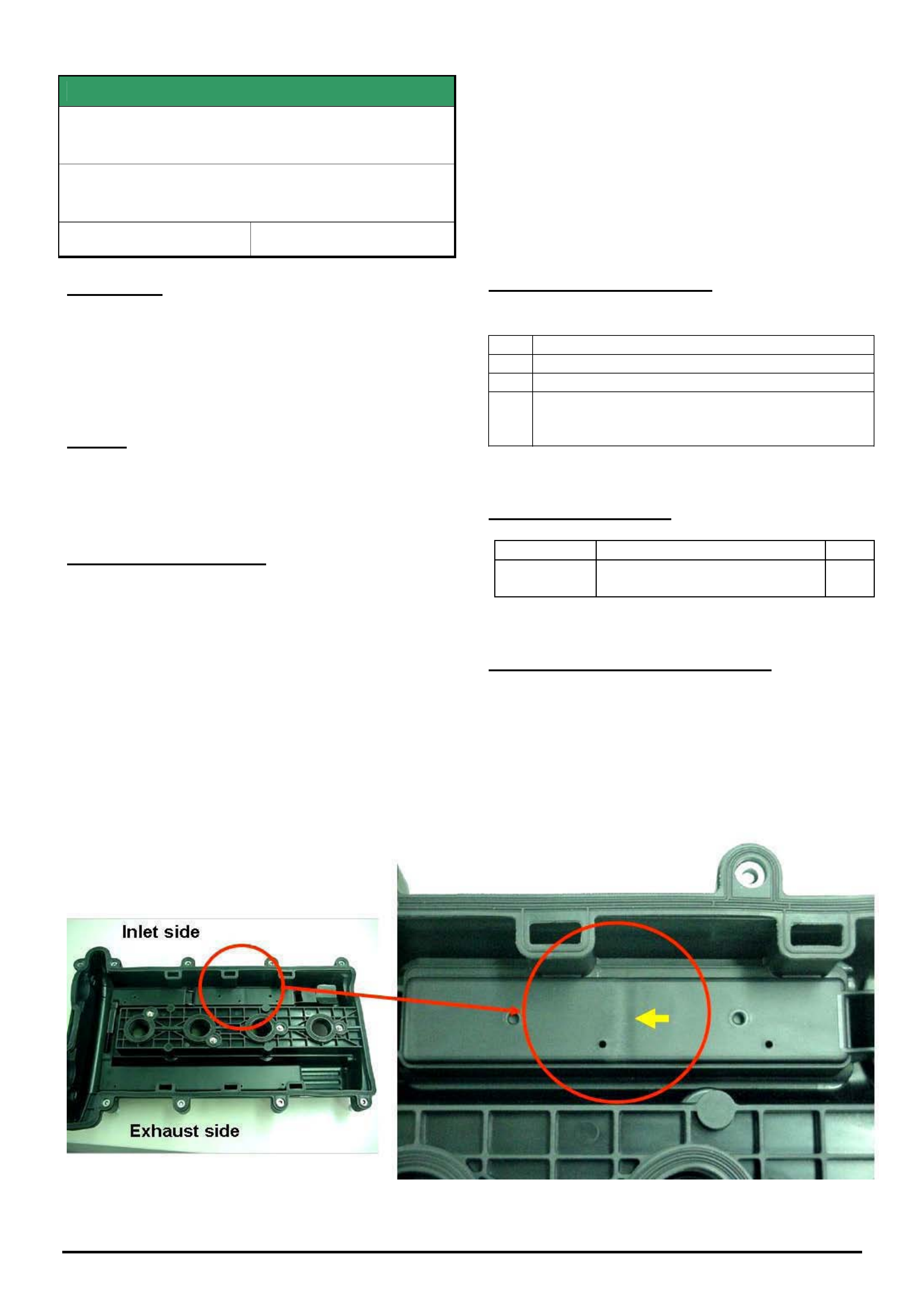
HOLDEN SERVICE TECHLINE __________________________________________________________________________________MAY, 2005
5
Holden Techlines are written to inform technicians of conditions that may occur on some vehicles, and to provide information that could assist in the
proper service fix of a vehicle. If a condition is described, do not assume the service fix applies to a vehicle or that the vehicle will have that condition.
SERVICE FIX
Excessive Engine Oil Consumption Due To
Faulty Cylinder Head Cover (Plastic Type)
ZC Vectra, TS Astra, TT Zafira, all with Z22SE
engine
Group 6A Ref. No. TL0805 - 0504
CONDITION
Some customers may report that their vehicle exhibits
the following symptoms;
1) Blue smoke coming from the exhaust and/or
2) High oil consumption
CAUSE
Positive crankcase ventilation passages within the
plastic cylinder head cover may not be to specification.
NOTE: The metal cylinder head covers are not
affected.
CORRECTION – Service
1. Confirm the customer complaint by conducting
a standard oil consumption test. When completed,
contact TAS to register a case and confirm if vehicle
has excessive oil consumption.
2. If TAS confirm that vehicle has high oil
consumption, proceed to check the cylinder head
cover for a possible manufacturing fault described as
follows.
3. Remove the cylinder head cover and inspect the
underside of the cover. A faulty cover can be identified
by a “sink” mark which is clearly evident as shown in
photograph below
4. A faulty cover should be replaced with a new
cover from HSPO. (If cover is not faulty contact TAS
for further advice). For removal and replacement
procedure refer to TIS 2000. .
CORRECTION – Production
Revised covers have been fitted to vehicles from:
ISOVIN:
ZC *********51010110
TT *********4H004812
TS *********5B000136 - Convertible
*********45123695 - SRi excluding turbo
PARTS INFORMATION
Part No.: Partfinder Name Qty:
13113034 Cover cylinder head (plastic)
includes gasket and fasteners
1
WARRANTY CLAIM INFORMATION
Use Labour Times information in Warranty Information
section of current PV SIP CD
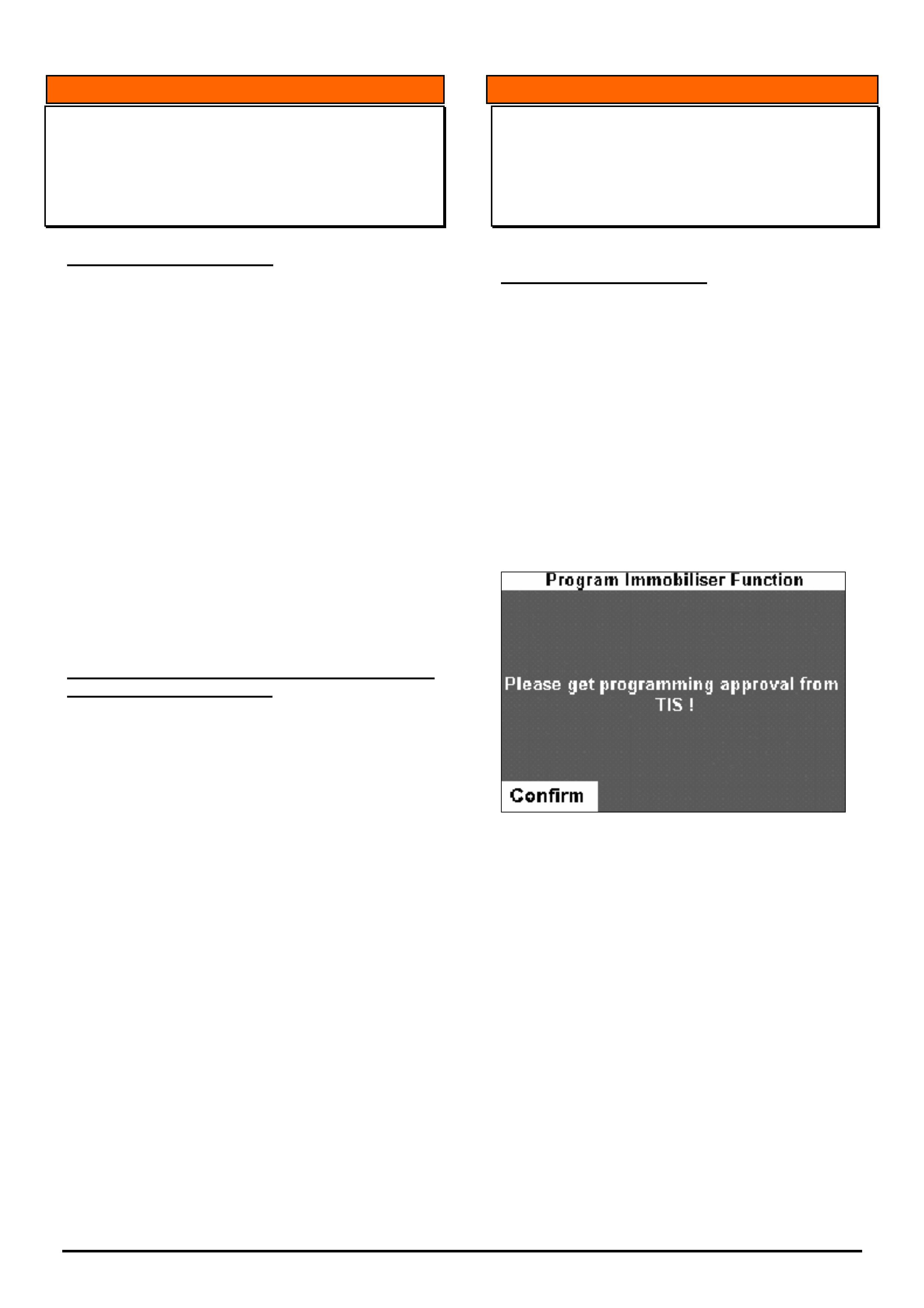
HOLDEN SERVICE TECHLINE __________________________________________________________________________________MAY, 2005
6
Holden Techlines are written to inform technicians of conditions that may occur on some vehicles, and to provide information that could assist in the
proper service fix of a vehicle. If a condition is described, do not assume the service fix applies to a vehicle or that the vehicle will have that condition.
INFORMATION
TIS Approval with Tech 2
All Vehicle Types
(GROUP OB) TL0903-0504
PROBLEM DESCRIPTION
Programming difficulties when trying to link
immobilizers or program keys, may be attributed to
the incorrect process of obtaining TIS Approval on
Tech 2.
Some programming difficulties have occurred when
technicians have got TIS Approval on Tech 2 before
going to the vehicle. THIS IS NOT THE CORRECT
PROCEDURE
Dealers are reminded that the correct procedure for
obtaining TIS Approval is to only connect the Tech 2
to TIS, AFTER the following message is displayed on
the Tech 2 screen when Tech 2 is connected to the
vehicle.
Failure to follow this procedure may result in
programming failures or unnecessary parts
replacements.
INFORMATION
Problems With Using Part Numbers
Identified With Tech 2
(GROUP OB) TL0909-0504
PROBLEM DESCRIPTION
Some dealers choose to order replacement
components using the part numbers stored in that
part. For example, if you were to replace an
instrument in a current VZ Commodore you could
obtain the part number by using the identification
data screen displayed on Tech 2.
This will generally lead to the incorrect part being
supplied.
You SHOULD NOT order parts using part
numbers obtained via Tech 2.
Only use part numbers from the most recent version
of Partfinder or Micro Cat.
If you have trouble identifying the correct part,
contact “Parts Technical Service” using the
information stored in Partfinder under the ‘Holden
Help’ tab.
NOTE: This information should also be passed to
your spare parts personnel!
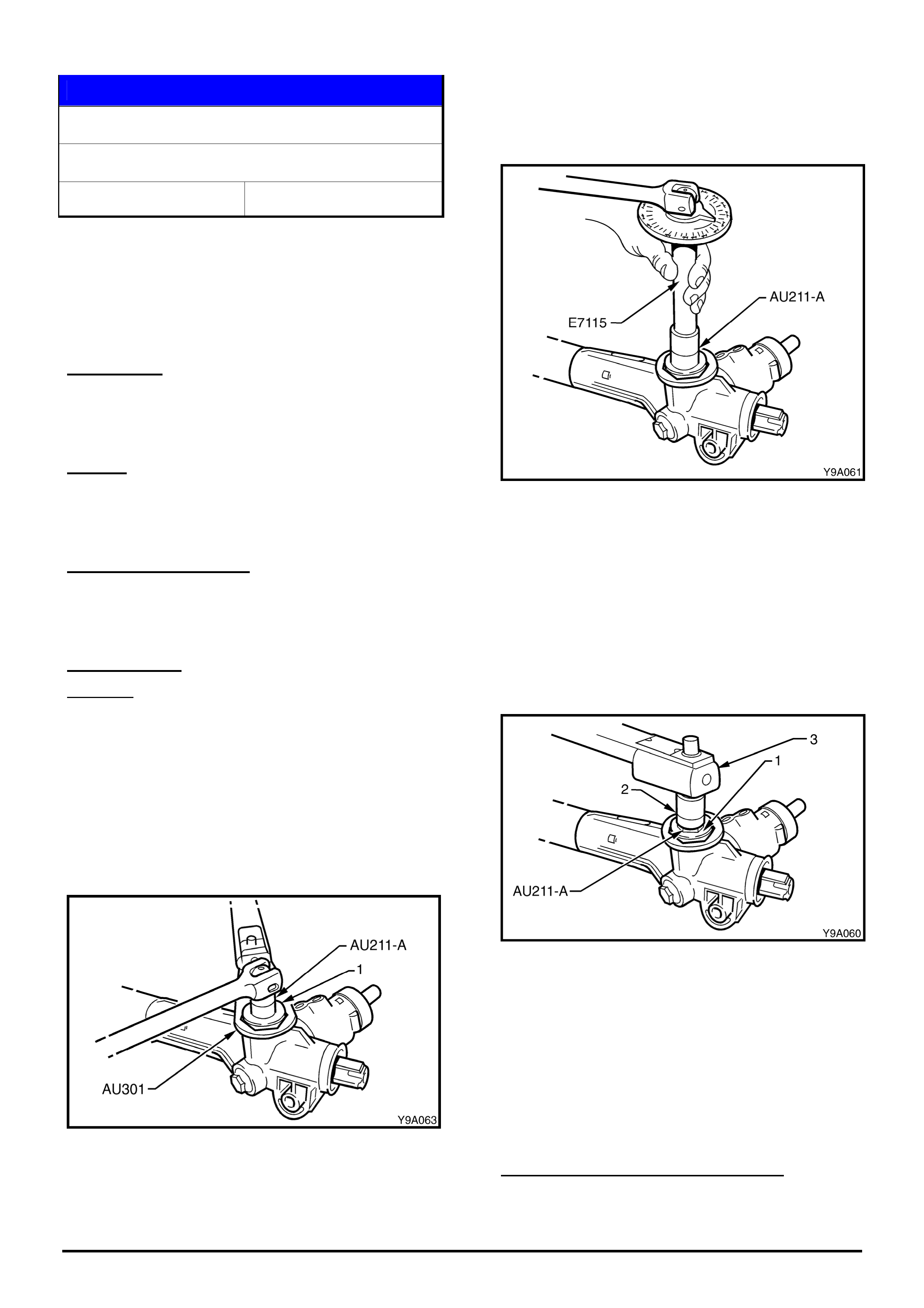
HOLDEN SERVICE TECHLINE __________________________________________________________________________________MAY, 2005
9
Holden Techlines are written to inform technicians of conditions that may occur on some vehicles, and to provide information that could assist in the
proper service fix of a vehicle. If a condition is described, do not assume the service fix applies to a vehicle or that the vehicle will have that condition.
SERVICE PROCEDURE
Power Steering Gear Rack Pad Adjustment.
VT, VX, VU, VY, VZ, V2, WH, WK, WL
Group 9 Ref. No. TL0907- 0504
Dealers continue to replace complete steering
gear assemblies for complaint of knock or rattle
which, in most cases, can simply be rectified by
performing rack pad adjustment as described in
this Techline.
CONDITION
Knock or rattle is reported as coming from the
steering.
CAUSE
Steering gear rack pad adjustment not to
specification.
PARTS INFORMATION
In order to perform a rack pad adjustment, special
tools AU211-A, AU301 and E7115 will be required.
CORRECTION
Summary: After verifying that the reported
knock/rattle is coming from the steering gear, adjust
the rack pad as follows.
NOTE: The Steering gear does not have to be
removed from vehicle to perform the following
procedure.
1. Using tool AU211-A and ring spanner tool
AU301 loosen rack pad adjusting screw lock nut
approx. 2 turns. Refer fig 1
Figure 1
2. With the steering rack in the centralised position,
tighten the rack pad adjusting screw, using tool AU211-
A, to the correct torque specification 10.0 – 12.0 Nm.
3. Using angle wrench tool no. E7115 and the rack
pad adjusting tool AU211-A, turn the rack pad
adjusting screw back (counter – clockwise) 20°- 28°.
Refer Figure 2.
Figure 2.
4. Apply loctite 567 thread sealant or equivalent to
the cleaned threads of the rack pad adjuster lock nut.
5. While holding the adjusting screw with tool
AU211-A and a socket bar in the position set in steps
2 & 3, (refer Figure 3) tighten the lock nut to the
correct torque specification using tool AU301 and a
suitable torque wrench.
Rack pad adjusting screw lock nut torque
specification 55.0 – 65.0 Nm.
Figure 3.
Once the rack pad adjustment has been performed
the steering gear must be racked from lock to lock to
ensure localised wear has not appreciably affected
the setting. The gear should not bind or appear tight
over any part of the total travel. Should the gear
appear tight or still rattle/knock recheck the rack pad
adjustment. If this is not the cause, replace the
steering gear.
WARRANTY CLAIM INFORMATION
If applicable, use Labour Times information in
Warranty Information section of current PV SIP CD.

HOLDEN SERVICE TECHLINE __________________________________________________________________________________MAY, 2005
10
Holden Techlines are written to inform technicians of conditions that may occur on some vehicles, and to provide information that could assist in the
proper service fix of a vehicle. If a condition is described, do not assume the service fix applies to a vehicle or that the vehicle will have that condition.
DIAGNOSIS HINT
Caster Rod Bush Replacement for Leaks
VZ & WL
Group 3 Ref. No. TL0912- 0504
CONDITION
Caster Rod bushes are being replaced unnecessarily
for reported symptoms of “leaking” and “causing a
clunk from the front suspension”.
CAUSE
Assessment of returned parts shows these bushes
are not leaking but are covered with excessive
assembly/shipping fluid which is applied during
manufacture.
Whilst the bush may appear to be leaking and
thought to be the cause of a clunk from the front
suspension, it has been confirmed that even if a bush
has a genuine leak and has lost all of its fluid it will
not cause a clunk/ knock in the front suspension.
CORRECTION – Service
To avoid misdiagnosis of the caster rod bush, do the
following.
1. Wipe bush of excess fluid.
If fluid appears to be trapped where the caster rod
passes through the centre of the bush remove
bush from vehicle and clean fluid from centre bore
of bush.
2. Confirm if fluid returns after cleaning. The vehicle
will have to be driven to put a load on the bush.
• If no more fluid appears the bush is OK.
• If bush is confirmed as leaking, replace bush.
DIAGNOSIS HINT
Engine Overheating Diagnosis Caution
VZ & WL with HFV6 Engine
Group 6K Ref. No. TL0913- 0504
CONDITION
PIR’s have been received by Holden regarding
complaints of “high temperature gauge readings”,
where technicians have replaced thermostats in an
attempt to correct the problem.
These thermostats, when returned to Holden for
testing, show No Fault Found.
CAUSE
As the thermostats are not at fault, it appears that
there is another cause for the high temperature
gauge readings.
The most likely cause is air entrapment in the engine
cooling system.
CORRECTION
As some technicians report that purely bleeding the
cooling system corrects the complaint condition we
would suggest the following approach.
1. Ensure the cooling system is correctly filled, and
bled according to SIP CD info.
2. Thoroughly check the cooling system cap, clamps
and fittings for security.
Tightening of hose clamps may be required in
case of “compression set” – i.e. after some
exposure to heating, cooling, etc, in a vehicle,
rubber hoses can take a “compression set” to a
reduced size created by the clamp. When this
occurs, clamps will ‘feel’ tight, but if the clamp
screw is backed off slightly then re-torqued, the
clamp screw will move to a position further on than
the original position because of the “set” size that
the hose has taken. (you have all seen the “clamp
imprint” in removed hoses - that is the “set” size).
Please PIR any causes for overheating that are
found and indicate corrective action taken.
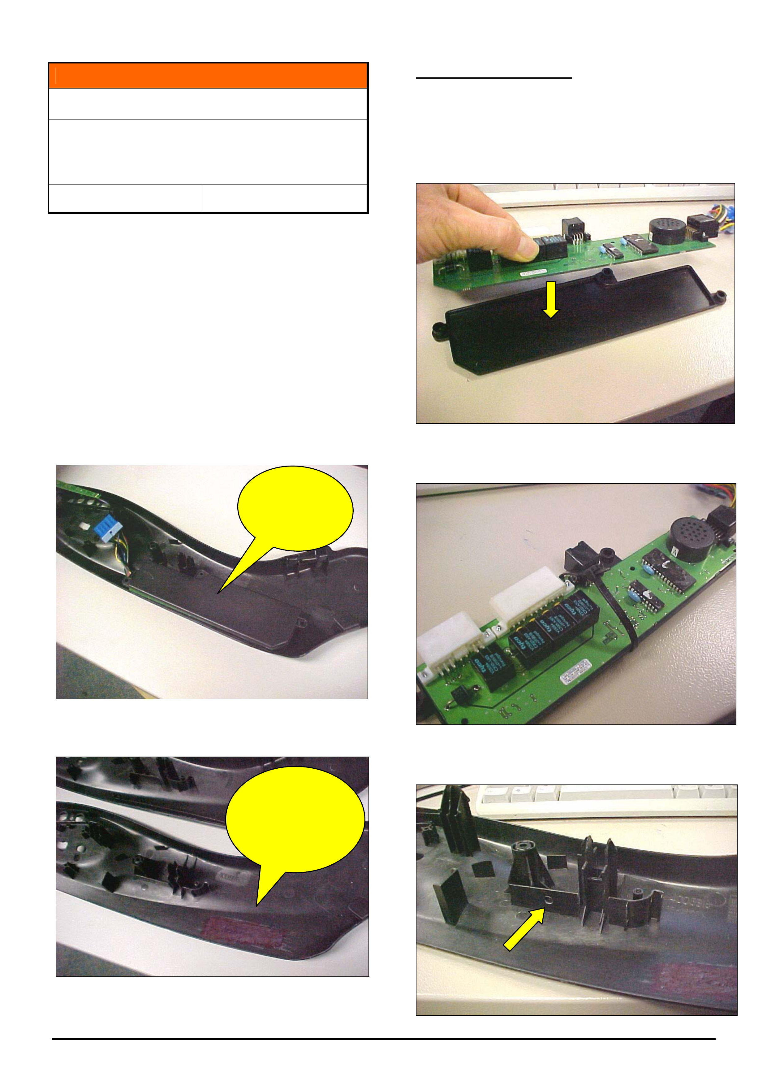
HOLDEN SERVICE TECHLINE __________________________________________________________________________________MAY, 2005
11
Holden Techlines are written to inform technicians of conditions that may occur on some vehicles, and to provide information that could assist in the
proper service fix of a vehicle. If a condition is described, do not assume the service fix applies to a vehicle or that the vehicle will have that condition.
INFORMATION
Revision To Front Seat Side Covers
V & W models fitted with seat memory
modules (Calais, Statesman, Caprice,
Monaro)
Group 1 Ref. No. TL0885- 0503
Whenever replacing the front seat side covers on
above models the modification shown below may be
required in order to attach the memory module to the
new covers.
Part Numbers affected:
92148281, 92148282, 92148279 92148280.
The above situation has arisen as a result of
revisions to side covers in production where the
mounting points for old level memory module were
removed.
Original Covers. (Memory module mounted to
cover)
Revised Covers (Module mountings removed)
SERVICE PROCEDURE
Attach memory module to new revised side cover by
performing the following procedure. This will require
two 190mm long by 5mm wide plastic cable ties.
1) Fit module board to the plastic cover from the old
assembly
2) Fit cable tie around module and board in the
location shown.
3) Drill Hole Dia 6mm through the centre of the
flange shown
Module
mounted on
side cover
Module
mountings
deleted in new
covers
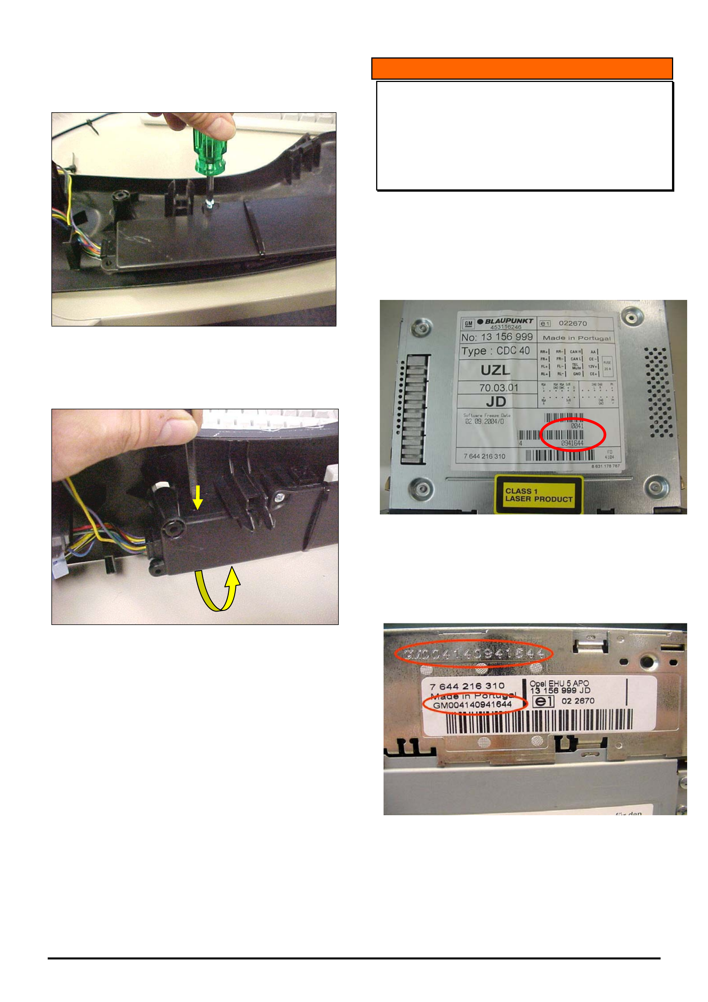
HOLDEN SERVICE TECHLINE __________________________________________________________________________________MAY, 2005
12
Holden Techlines are written to inform technicians of conditions that may occur on some vehicles, and to provide information that could assist in the
proper service fix of a vehicle. If a condition is described, do not assume the service fix applies to a vehicle or that the vehicle will have that condition.
4) Fit module to side cover using one of the original
screws into the only available screw boss
5) Pass cable tie through the Hole drilled
previously, and around the module; pull tight and
trim the excess.
INFORMATION
CDC 40 Opera Audio Unit Serial Number
Identification
ZC Vectra and AH Astra
(GROUP 12 ) TL0915-0504
Whenever replacing a CDC 40 Opera radio via the
warranty changeover program it will be necessary to
obtain the serial number off the unit. The serial
number is located on the top of the unit (refer Figure
1) and on the side (refer Figure 2.)
Figure 1. Top View.
The serial number is a combination of “GM” plus the
2 groups of numbers on the bar codes as shown. In
this example the number is GM00410941644.
Figure 2. Side View
The serial number is stamped into the body of unit
and is also shown on the printed label.

HOLDEN SERVICE TECHLINE __________________________________________________________________________________MAY, 2005
13
Holden Techlines are written to inform technicians of conditions that may occur on some vehicles, and to provide information that could assist in the
proper service fix of a vehicle. If a condition is described, do not assume the service fix applies to a vehicle or that the vehicle will have that condition.
INFORMATION
A/T Features
VZ/WL - All with A/T (non-AWD)
Group 7B Ref. No. TL0887- 0504
Introduction
Recent introduction of the 5L40E automatic
transmission to V and W cars has brought some new
features to both drivers and service technicians.
As some of the features may seem unusual to
drivers, the following information will assist
technicians and Dealership-front-counter-personnel
to understand the features and clarify any concerns
raised by vehicle owners/operators. Also, while
4L60E A/T is still in use, some significant revisions to
its characteristics have been made.
Comments from PIR’s, TAS, SMA and Foremen’s
meetings has prompted the publication of the
following information. This will assist Service front
counter personnel in assisting customers with
explanations of any transmission and vehicle
characteristics that may be confusing to them, and
assist service technicians when any such concerns
may be reported as “problems”.
Service Replacements
Before any consideration is given to replacing any
A/T in VZ or WL vehicles, refer to the information
below to ensure any customer concern is not a
characteristic of the current vehicle/transmission
configurations.
Dealer Letter DL44/04 was released regarding the
inclusion of the 5L40E transmission in the existing
SRTA program and allowable parts replacement -
refer to this letter before performing any transmission
diagnosis, parts replacement, or transmission
replacement.
If any concern exists that is not covered by DL44/04
or this bulletin, your nominated TAS contact should
contact TAS, after performing diagnosis and before
replacing a 5L40E transmission.
5L40E Automatic Transmission
Overview.
- 5L40E uses latest generation production-released
GM hardware strategy.
- Used in CTS Cadillac, BMW 3 and 5 Series, X5
and Range Rover diesel.
- Consumer Reports Magazine, believes "The five-
speed automatic transmission in the BMW, made
by General Motors, is about the best we've ever
experienced.“
- Holden localised 5L40E to suit our vehicles and
achieve primary objective – a shift quality that’s
smooth, crisp and seamless.
- Transmission shifts up to 6500rpm.
- Introduction after a three-year design, development
and testing program.
Shift Stabilisation Mode
The 5L40E automatic transmission features a “shift
stabilisation” mode which reduces busy shifting or
“hunting”, where the transmission seems unsure as
to which gear to remain in and shifts up & down in
order to keep the vehicle travelling at a constant
speed.
The shift stabilisation mode evaluates the speed,
load & current gear of the vehicle and calculates if it
would be able to hold the same load conditions if the
transmission upshifted to the next highest gear.
If the vehicle would be unable to hold the load
conditions in the next highest gear the shift
stabilisation mode prevents the upshift, as the upshift
would be followed shortly by a downshift once the
vehicle loses speed as it is unable to hold the
speed/load condition in the higher gear. In real world
scenarios - driving uphill - this reduces ‘busy shifting’
or ‘hunting’.
Performance Algorithm Liftfoot (PAL)
The 5L40E automatic transmission also features
adaptive shift characteristics, via software that
continuously evaluates driving conditions and driver
inputs, and reacts appropriately to how the vehicle is
being driven.
These adaptive shifts occur only with the
transmission in Power mode, they become active
after the driver uses a high throttle opening for a
short time period, followed by a sharp lifting of the
throttle eg. lifting off the throttle when entering a
corner. When in this “performance” mode, PAL
responds to driver requests or driving style - and to
operate it requires greater than three quarter throttle
pedal travel followed by a rapid pedal release -
hence the “liftfoot” description.
The transmission will react by holding gear instead of
upshifting when the throttle is released, if the driver
also slows down the vehicle, the transmission will
downshift gears at higher speeds than normal. Once
the control system determines the vehicle is being
driven in a “spirited” manner, the current gear is held
during acceleration. This assists with acceleration
out of a corner, resulting in the vehicle being in a
more suitable gear to assist in stability during
cornering and providing a more stable exit feel.
Both of these actions will assist when the vehicle is
driven in a sporty manner eg, through corners as the
lower gearing assists engine braking into corners
whilst holding gears will give better acceleration once
the throttle is re-applied.
Active Select (A/S)

HOLDEN SERVICE TECHLINE __________________________________________________________________________________MAY, 2005
14
Holden Techlines are written to inform technicians of conditions that may occur on some vehicles, and to provide information that could assist in the
proper service fix of a vehicle. If a condition is described, do not assume the service fix applies to a vehicle or that the vehicle will have that condition.
Active Select is for the drivers who like to take more
direct control of transmission shifts, as it allows them
to select the most appropriate gear for the current
conditions. Safety features include maximum and
minimum allowable engine speed control.
Shift “Busyness”
There are five gears, instead of the previous four as
in VY and earlier models, and these provide a more
“seamless” power application during acceleration.
In combination with the new Alloytec V6 engine, the
new T68 transmission controller uses current vehicle
operating conditions such as - engine speed, trans
input speed, throttle position, torque converter slip,
altitude and temperature to create a strategy for
optimum shift performance.
The controller has the ability to sense and
compensate for all these variables, allowing the
trans. to maintain consistent, optimum shift quality.
An additional gear allows the shift points to be
engineered to deliver an improved launch, while at
the same time delivering improved fuel economy -
this may be evident by rapid shifting or ‘holding’ in
gears during shifts - this will probably be most
noticeable in Power mode and ‘lift foot braking’ (IE:
does not shift ‘up’ but holds the lower gear, based on
Power mode selection and current driving style).
4L60E - Four Speed Auto. Trans.
In VZ, the 4L60E has received some subtle
improvements in reduced downshift delays and shift-
to-shift points, plus overall improvements have
resulted in a more integrated powertrain ‘feel’
between the Electronic Throttle Control (ETC) and
the transmission, providing better shift stabilisation
and consistency.
Transmission Controller
- New electronic architecture within Alloytec allows
introduction of more advanced (and commonised)
transmission control module and software
language.
- This new TCM software introduces more possible
calibration variables - 8448 compared with the 625
in previous TCM.
- The new software language allows processing of
larger amounts of information and does it faster.
- The programming of calibration variables
underwent extensive development and refinement
by Holden calibration engineers.
- Downshift sequencing is employed on both V6 and
V8 applications. Depending on vehicle speed, slow
to medium rates of throttle apply will result in a
single downshift while rapid rates of throttle apply
will result in a ‘jump shift’ (i.e. 4-2 as opposed to a
4-3 followed by a 3-2 downshift). The V6
transmission calibration makes greater use of this
‘jump shift’ algorithm.
Engine Clutch Control Capacity (ECCC) and torque
converter
- Upgraded ECCC allows partial lock-up or controlled
slip, thereby improving the feel and fuel economy
of an already efficient transmission.
- A new torque converter better matches the new
torque characteristics of the engine.
- Increased accuracy and change to the coupling
point of the converter match the engine torque
characteristics to vehicle response.
- Provides improved engine-transmission integration,
improved cooling and optimised fuel economy.
Brake Torque Management (BTM) - Applicable
to both 5L40E & 4L60E
BTM is a safety feature and is now a standard
feature for these vehicles.
The over-riding requirement is for a vehicle to be
able to be stopped from 100km/h in a specified
distance with full throttle application and a specified
brake load.
The way this is effected is slightly different in HFV6
and V8 applications because of the different
controllers and software types used.
In V8, if the brake pedal switch is activated at the
same time as the accelerator, torque is limited -
achieved by cutting fuel to cylinders.
In HFV6, if the engine speed is above a threshold
(approx. 1200rpm) AND
Vehicle speed is above a threshold (approx. 10km/h)
AND
Either of the brake switches is actuated,
then after a 2.5 second delay BTM is activated. In
BTM mode, torque is limited to that commanded at
25% accelerator pedal position.
It should be noted that the BTM feature is switched
off when Traction Control is switched off (where this
is possible).

HOLDEN SERVICE TECHLINE __________________________________________________________________________________MAY, 2005
15
Holden Techlines are written to inform technicians of conditions that may occur on some vehicles, and to provide information that could assist in the
proper service fix of a vehicle. If a condition is described, do not assume the service fix applies to a vehicle or that the vehicle will have that condition.
DIAGNOSIS HINT
Seat Track Height Adjuster Replacement
V & W
(GROUP 1) TL0735A-0504
This techline is being released due to Dealers
continuing to replace complete seat height
adjuster assemblies for conditions that can be
rectified via previously released techline
procedures.
In future, if a seat track height adjuster assembly
is replaced, it will be mandatory for the warranty
claim 3Cs to state that the relevant techline
procedure did not/will not rectify the condition.
__________________________________________
Refer to the following techline articles for the
available V & W car seat height adjuster repairs.
• Dampener Spring Fitted To Fore / Aft Drive
Shaft.
Notchy Fore / Aft Movement On 6 & 8 Way Front
Seats.
March, Issue 2, 2005 (Page 4).
• Seat Track Out Of Alignmenet
Seat Track Excessive Fore / Aft Movement Or
Loose. Applies to 2 & 4 ways seat height
adjuster (base model variants) built after April
2003.
October, Issue 9, 2004 (Page 11).
• Thicker Washer Available For Lead Screw
Nut.
Front Seat Fore / Aft Movement – 8 Way Seats.
August, Issue 7, 2004 (Page 18).
• Replacement Steel Clevis Nut
Seat Height Adjuster Inoperative, Disengaged
Thread.
September, Issue 9, 2003 (Page 7).
DIAGNOSIS HINT
Steering Wheel Radio Remote Control
Switches Function Incorrectly
VY / WK / V2 Series II & III
Group 12 Ref. No. TL0889A - 0504
This Techline supercedes the previous one in Issue
3, Apr, 2005. It is revised by correcting the model
affected from WL to WK.
Blaupunkt receive a large number of requests for
changeover radios due to customers and dealers
experiencing the incorrect function when the steering
wheel remote buttons are depressed.
The majority of these complaints are not due to a
fault with the radio. Therefore, to avoid incorrect
diagnosis, perform the following checks. These
checks are designed to determine if there is a poor
connection between the remote control switches and
the radio causing a high resistance which results in
the incorrect function.
Checking Procedure
1. Remove the radio. Use a multi meter to
measure the resistance between terminals C11 &
C12 in the X1 connector; when no buttons are
depressed the resistance should be approximately
3674 ohms.
2. When each of the following switches are
depressed the resistance measured should be
approximately as listed below.
Next up button 794 ohms
Mute button 284 ohms
Next down button 464 ohms
Volume up button 164 ohms
Mode button 1474 ohms
Volume down button 82 ohms
3. If a high resistance is detected, disconnect all
connections, inspect for damage or corrosion,
reconnect and measure the resistance again. If the
resistance has changed and the correct function of
the radio remote switches is achieved then the
problem is considered to be connection related.
4. If the fault is still present, use the wiring
diagrams, check each section of the circuit separately
(wiring harness, clock spring, radio remote switches) to
allow diagnosis of the faulty component. .
NOTE: When measuring the resistance of this circuit,
ensure that any probing does not deform the
terminals in vehicle harness.
If the fault still persists after performing the above
diagnosis, contact Blaupunkt for additional diagnosis
assistance and advise that you have completed
these checks.

HOLDEN SERVICE TECHLINE __________________________________________________________________________________MAY, 2005
16
Holden Techlines are written to inform technicians of conditions that may occur on some vehicles, and to provide information that could assist in the
proper service fix of a vehicle. If a condition is described, do not assume the service fix applies to a vehicle or that the vehicle will have that condition.
Air Intake Duct Dislodges, Sets Codes
P0171, P0174
HSV WK/VY with Gen III V8
Group 6A Ref. No. TL0908 - 0504
CONDITION
PIR’s report the occurrence of DTC’s P0171 & P0174
(Lean exhaust codes).
CAUSE
Air inlet duct from air flow meter to throttle body
dislodges.
Initial installations of this duct on HSV enhanced
vehicles had no hose retaining lip
CORRECTION – Production
The first vehicle fitted with revised air duct (with a
retaining lip) - p/n 06M3030602 - was L113977 -
where the duct was fitted during HSV enhancements
on 11/11/03.
NOTE: HSV vehicles are not built or enhanced in
strict VIN/Tag No. order, so the enhancement date is
the best indication. IE: any vehicle enhanced after
11/11/03 will be fitted with the revised part.
Reference only:
ISOVIN: Built Date:
6G1KY54F24L113977 23/05/03
CORRECTION – Service
Summary:After verifying that vehicle has condition as
described above, fit a new inlet duct.
PARTS INFORMATION
Part No.: Partfinder Name Qty:
06M3030602 Duct - Air Flow Meter to
Throttle Body.
1
WARRANTY CLAIM INFORMATION
Use Labour Times information in Warranty
Information section of current PV SIP CD
INFORMATION
Checking TIS 2000 Version Number
GROUP OB TL0924-0504
The latest version of TIS (and other service
information Cd’s) is published at the beginning of
each Techline Issue under the heading:-
‘Your Latest Electronic Service Information’.
To confirm which version of TIS2000 is loaded on
your PC proceed as follows.
From the TIS main screen click ‘Help’ from the top
menu bar, then click ‘About TIS 2000’ refer Figure 1.
In the ‘pop up’ is the current version of service
information installed. Refer figure 2.
In this example the current version is:
Opel/Vauxhall/Holden/Version 60.1 Domestic.
TIS 2000 – Isuzu GE/DO Version 16.0 (Isuzu
General Export Domestic)
Wiring Diagram – Version 19.0
Note: For instructions on how to download TIS 2000
Isuzu software into Tech 2, refer Techline Issue 2
March 2004.
Figure 1.
Figure 2.
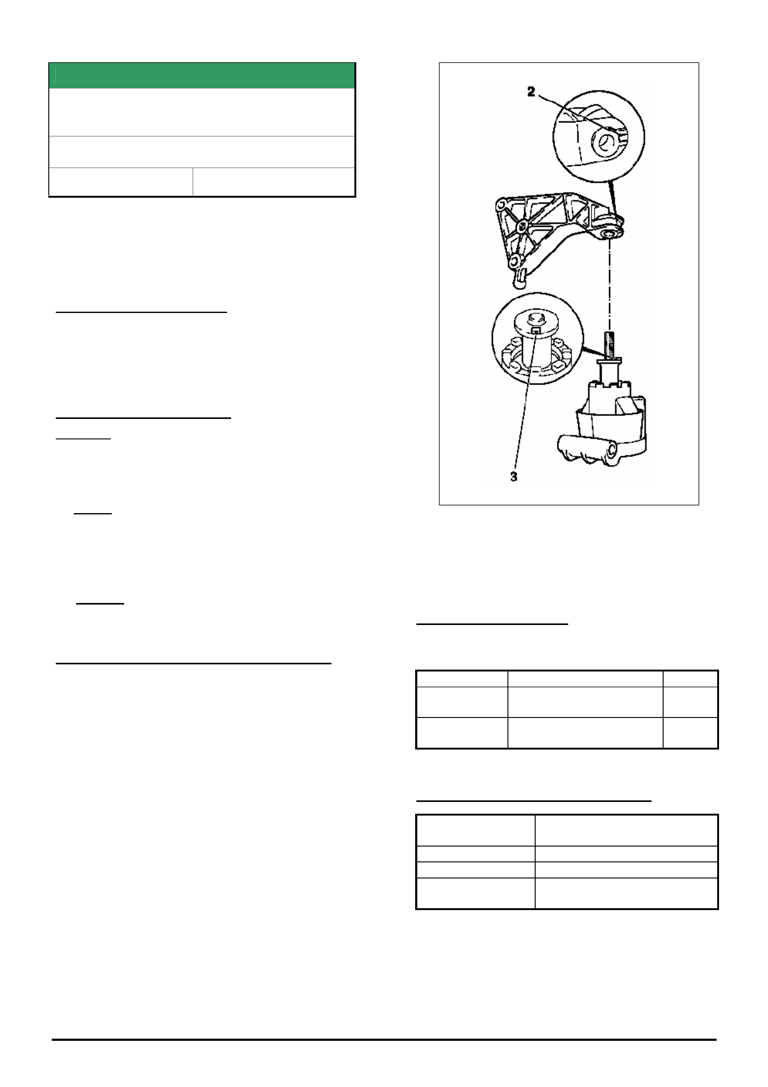
HOLDEN SERVICE TECHLINE __________________________________________________________________________________MAY, 2005
17
Holden Techlines are written to inform technicians of conditions that may occur on some vehicles, and to provide information that could assist in the
proper service fix of a vehicle. If a condition is described, do not assume the service fix applies to a vehicle or that the vehicle will have that condition.
SERVICE FIX
Engine Vibration – Loose Engine Mount
Bolt
TS 1.8L Engine
Group 6A Ref.No. TL0247A - 0504
This Techline is Re-issued from Issue 3, Apr
2002, to draw technicians attention to the need
for engine mount bolt checking during vehicle
servicing.
PROBLEM DESCRIPTION
PIR’s have been received that mention
engine/transmission vibration – and diagnosis has
shown that a loose/missing rear powerplant mounting
bolt was the cause.
SERVICE RECTIFICATION
Summary: Refit/Replace bolt and Apply Loctite 243.
Should diagnosis of a “vibration” complaint define
that a rear powerplant mounting bolt is:
a/. Loose – remove the mating nut, apply Loctite 243
(or equivalent) to the bolt threads and refit the nut,
and torque to 55Nm.
OR
b/. Missing – Fit a new bolt and nut (from HSPO),
apply Loctite 243 (or equivalent) before installation
and torque to 55Nm.
Rear Engine Mounting Assembly Precaution.
Note: when attaching the damper block to the
(upper) bracket – ensure the raised “key” section (3)
of the damper is located in the recess (2) in the
bracket, as shown in Figure 1.
Figure 1.
For Reference: The above diagram is taken from TIS
2000 – Refer to the relevant TIS 2000 section when
replacing engine/powertrain mounts.
PARTS INFORMATION
Use the following parts ONLY when replacement of
missing parts is required:
Part No.: Description: Qty:
11098991 Bolt – Damper to
Bracket.
1
11098811 Nut – Damper to
Bracket.
1
WARRANTY CLAIM INFORMATION
Description Engine mount bolt/nut -
Replace
Labour Op. No. J000704
Time 0.3 hr
Failure Code 27 (Loose) or
29 (Part Missing)
NOTE. Tightening a loose bolt is not considered
warranty but part of the routine maintenance service
checking procedure

HOLDEN SERVICE TECHLINE __________________________________________________________________________________MAY, 2005
19
Holden Techlines are written to inform technicians of conditions that may occur on some vehicles, and to provide information that could assist in the
proper service fix of a vehicle. If a condition is described, do not assume the service fix applies to a vehicle or that the vehicle will have that condition.
SERVICE FIX
Hard to Select Gears
VT2,VX,VU,VY,V2,VZ with V8 & MM6 M/T
Group 7A Ref. No. TL0840 - 0504
For complaint of “Hard To Select Reverse Gear
Only” refer to Techline TL0914 – 0504 which
explains the revisions to the reverse synchroniser
blocker ring.
CONDITION
Customer reports hard to select gears. Initially, it may
be First and Reverse and then eventually the
customer experiences high shift effort into all gears.
CAUSE
Possible lack of lubrication of clutch and input shaft
splines resulting in the clutch disc binding on input
shaft and not fully releasing from flywheel..
CORRECTION – Production
Lubrication added from:
ISOVIN: Built Date:
6G2VX12U55L282597 10/12/04
CORRECTION – Service
1. Measure transmission spin down time.
Engine at idle speed and transmission in neutral.
Depress clutch pedal and measure time by listening
for input shaft to stop spinning. Transmission roll
over noise can be used to determine spin down time
and is best heard by squeezing gear lever. Spin
down time should be no greater than 2 seconds
2. If spin down time is greater than 2 seconds, clean
and lubricate transmission input shaft spline. Refer
to Holden SIP CD for correct grease type to be used.
3. If spin down time is less than 2 seconds then this
is not likely to be the cause of high shift effort.
Further diagnosis will be required to identify problem.
Contact TAS if further diagnosis assistance is
required.
WARRANTY CLAIM INFORMATION
Use Labour Times information in Warranty
Information section of current PV SIP CD.
SERVICE FIX
Hard to Select Reverse Gear Only
VT2,VX,VU,VY,V2,VZ with V8 & MM6 M/T
Group 7A Ref. No. TL0914 - 0504
CONDITION
Hard to select REVERSE gear under all conditions
(hot and cold).
CORRECTION – Production
To overcome the above condition the reverse gear
synchroniser blocker ring has been revised from
bronze to steel with a carbon lining.
Transmissions with this revision were introduced into
vehicles from:
ISOVIN: Built Date:
6G2VX12U55L363449
(Trans. Serial No. TB010072)
22/11/04
CORRECTION – Service
STEP 1.
Perform procedures outlined in Transmission
Diagnostic chart shown in All Dealer Letter DL06/05 -
entitled:
Chart 2 - Manual Trans. “Hard to Select Gears”
STEP 2.
If after completing step 1 the customer complaint
cannot be rectified, install a new Reverse gear
synchroniser ring 92143258 (carbon lined)
NOTE: This blocker ring is also specified for use on
5th/6th gear synchro assembly.
PARTS INFORMATION
Part No.: Partfinder Name Qty:
92143258 Blocker Ring (Steel with
carbon lining)
1
WARRANTY CLAIM INFORMATION
Use Labour Times information in Warranty
Information section of current PV SIP CD
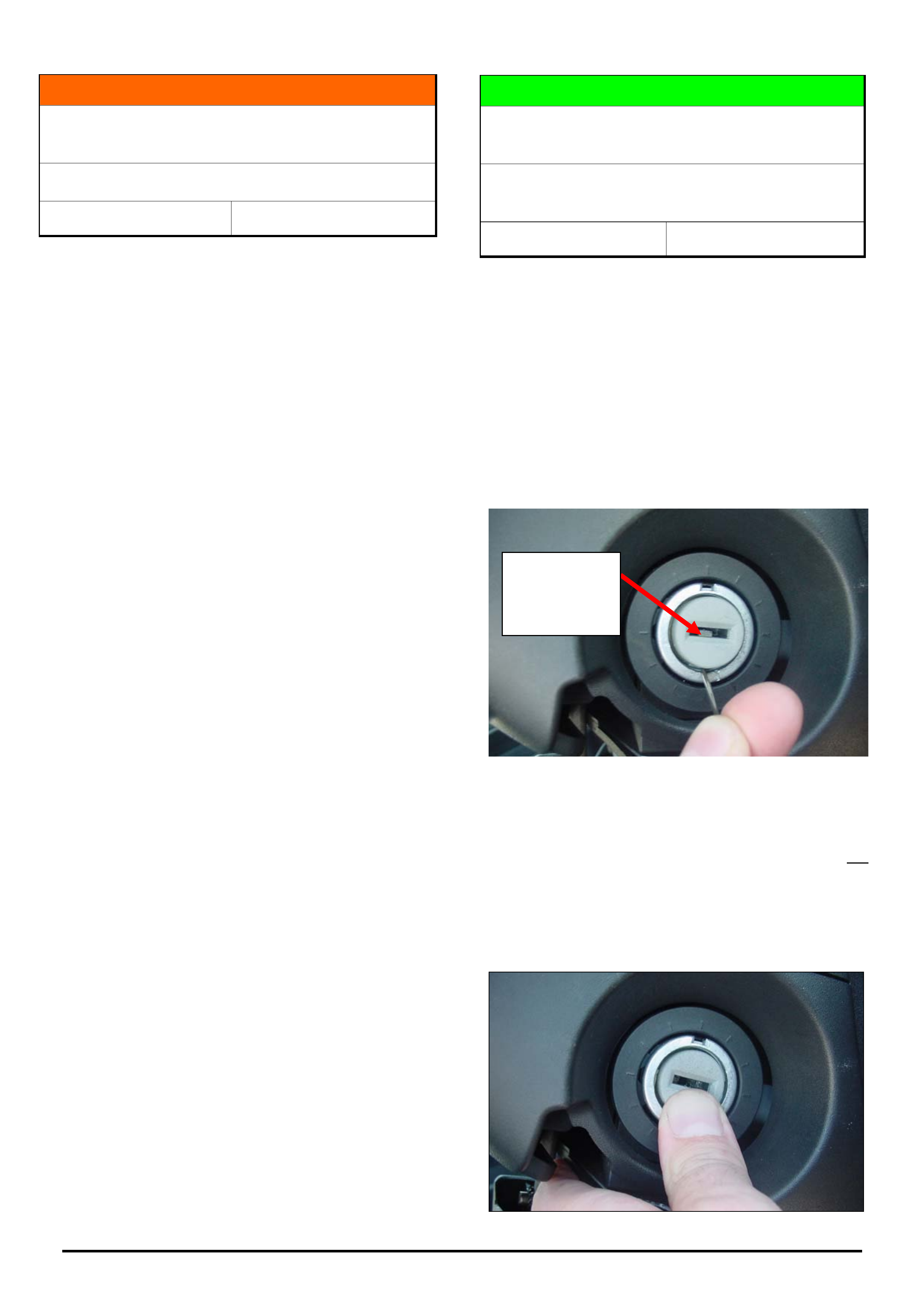
HOLDEN SERVICE TECHLINE __________________________________________________________________________________JUNE, 2005
5
Holden Techlines are written to inform technicians of conditions that may occur on some vehicles, and to provide information that could assist in the
proper service fix of a vehicle. If a condition is described, do not assume the service fix applies to a vehicle or that the vehicle will have that condition.
INFORMATION
Camshaft Drive Belt Maintenance Service
Interval Clarification
ZC with 3.2L V6 Engine
Group 6A Ref. No. TL0905 - 0505
The service maintenance interval for the camshaft
drive belt, tensioner assembly, idler pulley, and return
roller have been changed.
The maintenance interval is now as follows:
120,000km or 8 year Intervals
• Engine toothed belt, tensioner assembly, idler
pulley, and return roller - Replace.
• Engine tooth belt crank drive gear - Inspect .
NOTE. Initial copies of the owners handbook
specified that the above service be performed at
60,000 km or 4 year intervals. Owners handbooks with
the new intervals were printed from Sep.2004
(commencement of Model Year ‘05)
If you have a vehicle where the owners handbook
specifies the 60,000km maintenance interval, please
refer this to your service manager.
SERVICE HINT
Ignition Barrel Jams In Off Position –
Alternate Method For Freeing Up Barrel
TS, TT, XC, with “S” profile Ignition
Keys/Barrels
Group 9 Ref. No. TL0935 - 0505
Further to earlier techline titled “Ignition Key Jams In
The Off Position Or Is Difficult To Turn From Off”
released in issue 2 Page 20, 2005, this techline offers
an alternative method for rotating a seized ignition
barrel. This procedure will assist in mobilising a vehicle
so that it can be moved to a workshop for repair.
1. Remove the ignition barrel rubber surround.
2. Insert a seal pick between the barrel and outer
housing and raise the key retaining plunger as show in
figure 1 so that it is fully visible in the key slot.
Figure 1.
3. Press the barrel centre in (usually 2 – 4mm) and
hold, then remove the seal pick.
Note: If the key retaining plunger is not fully raised so
that it is visible in the key slot, the barrel centre will not
press inward.
4. While still holding the barrel centre in as shown in
figure 2, insert the key and rotate to mobilise the
vehicle.
Figure 2.
Key retaining
plunger in the
raised
p
osition.
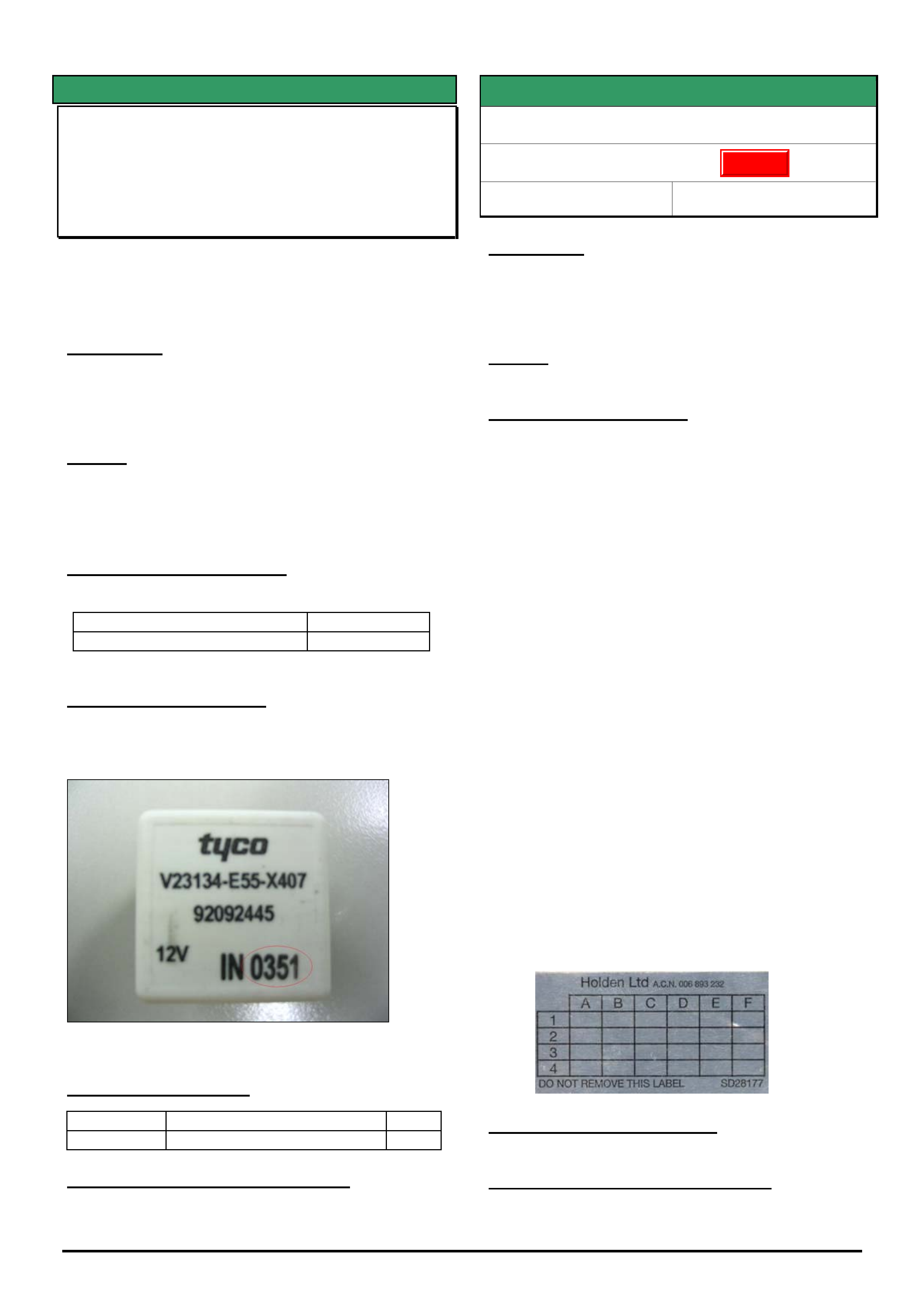
HOLDEN SERVICE TECHLINE __________________________________________________________________________________JUNE, 2005
6
Holden Techlines are written to inform technicians of conditions that may occur on some vehicles, and to provide information that could assist in the
proper service fix of a vehicle. If a condition is described, do not assume the service fix applies to a vehicle or that the vehicle will have that condition.
SERVICE FIX
Low Speed Engine Cooling Fan Relay Sticking
On
VY, WK, V2 II & III, VZ, WL
(GROUP 12) TL0929-0505
This Techline supercedes the previous one in Issue 3,
April, 2004 (TL0673-0403). It is revised by adding a
change to the affected model ranges, production and
parts break points.
CONDITION
Engine cooling fan remains on continuously after
ignition is switched off. In some instances the vehicle
battery may be fully discharged.
CAUSE
Contaminant on internal relay contacts due to a quality
control issue at the relay manufacturer. Relays from
the suspect batch were fitted to all vehicles built
between Jan 03 and Jun 04.
CORRECTION - Production
Known good relays were fitted to vehicles from:
ISOVIN: Built Date:
**********L425282 08/04/2005
CORRECTION – Service
On vehicles affected by this condition, replace the
relay with one where the date code, as shown in
Figure 1, reads “IN 0423” or higher.
Figure 1
PARTS INFORMATION
Part No.: Description: Qty
92092445 Low Speed Cooling Fan Relay 1
WARRANTY CLAIM INFORMATION
Use Labour Times information in Warranty Information
section of current PV SIP CD
SERVICE FIX
A/T Shift Pattern/Sports Mode Concerns
AH Astra
Group 7B Ref. No. TL0934A - 0506
CONDITION
Some customers may complain or comment about
poor performance, cabin booms in normal driving
mode, and/or holding gears until redline when in sports
mode.
CAUSE
Automatic Transmission Calibration.
CORRECTION – Service
If a customer complains about the above described
conditions, reprogram the Transmission Electronic
Control Unit via the standard Service Programming
System (SPS) method using TIS 2000, CD 61 or later.
IMPORTANT: During SPS programming, the Country
Of Registration must be set to Australia. If this is left as
“Other” an error message will advise that the vehicle
currently has the latest calibration.
The latest transmission calibration installed off TIS
2000 CD 61 has the following revisions:
'Normal' driving mode - Revision in shift points and
lock up points for torque converter (occurring slightly
later in RPM range compared to current production
calibration). This improves performance feel, where
engine won't labour, and also reduces cabin booms.
'Sports' driving mode - Revision in shift points, where
auto transmission won't hold in gears until redline.
Improved Calibration Details:
Opel Part No. 55560969 Software Version No. 1010.
To identifiy vehicles that have had the above
procedure performed, apply a service history label on
the the inner left side of the glovebox door and mark
the coordinate “A-2” with a ball point pen to indent the
foil sticker. Refer following figure.
CORRECTION – Production
Breakpoint details will be published when this occurs.
WARRANTY CLAIM INFORMATION
Use Labour Times information in Warranty Information
section of current PV SIP CD
x
Update
HOLDEN SERVICE TECHLINE __________________________________________________________________________________JUNE, 2005
7
Holden Techlines are written to inform technicians of conditions that may occur on some vehicles, and to provide information that could assist in the
proper service fix of a vehicle. If a condition is described, do not assume the service fix applies to a vehicle or that the vehicle will have that condition.
DIAGNOSIS HINT
Blaupunkt Audio Unit Insufficient Volume -
(Dynamic Distortion Limiting Function)
VY & VZ ute
Group 12 Ref. No. TL0928 - 0505
CONDITION
Customer complains that there is insufficient volume
output from the audio unit in their vehicle particularly
when playing music with a lot of bass.
CAUSE
The most likely cause for the customer complaint is the
Dynamic Distortion Limiting (DDL) function in the audio
unit is turned on.
In most instances, the customer would be unaware of
this feature and the fact that it can be turned off or on
via the radio controls.
CORRECTION
Advise the customer of this DDL feature which is
explained in the audio system handbook and the
owners handbook. Show them how to switch the
feature Off if they wish to do so. The following
procedure is extracted from the audio system booklet.
1. Turn off the radio using the “OFF” button.
2. Push and hold the “ON” button and the preset 1
button until the display shows “Options Menu”, then
release the buttons. The display will initially show the
current setting for “Confirmation Beeps”.
3. Press the volume knob momentarily a couple of
times to scroll through the options until DDL is
displayed.
4. Turn the volume knob clockwise or anticlockwise to
turn DDL ON or OFF.
NOTE: This is not a warranty rebill item as there is no
defect in the vehicle.
SERVICE FIX
Wagon Third Row Accessory Seat –
Seat Back Release Cable Breaks
VT, VX, VY, VZ
Group 1 Ref. No. TL0881 - 0505
CONDITION
Seat back release cable breaks.
CORRECTION
On seats with the above condition, replace the cable.
Do not replace the entire seat assembly when
replacement of the cable will rectify the problem.
NOTE: Previously, this cable was not available as a
replacement part. It can now be obtained through
HSPO.
Replacement Procedure.
Instructions are included with each kit.
PARTS INFORMATION
Part No.: Partfinder Name Qty:
92149039 Third Row Seat - seat back
release kit
1
WARRANTY CLAIM INFORMATION
Description Replace 3rd row seat back
release cable
Labour Op. No. R902210
Time 1.0 hr
Failure Code R0001
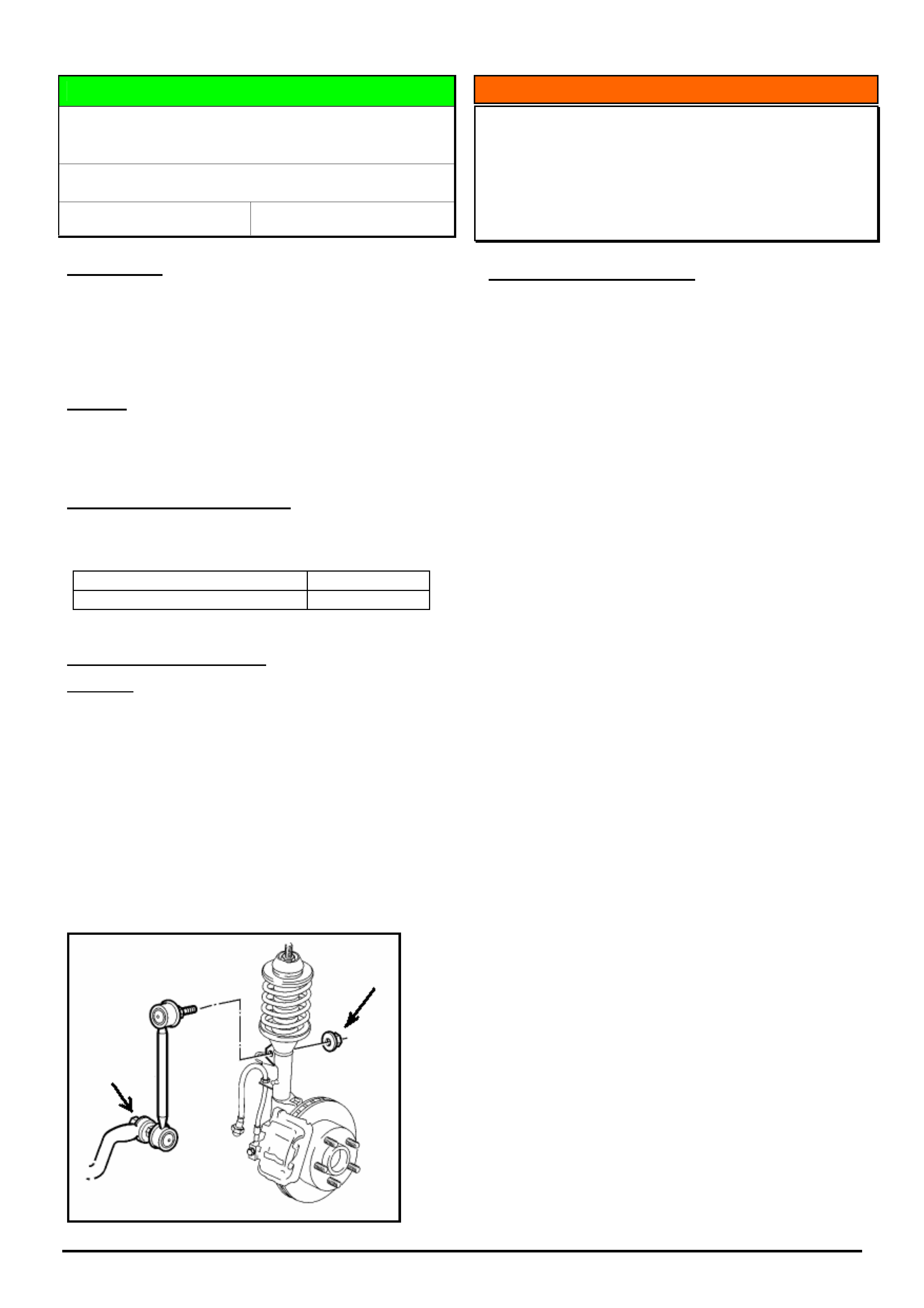
HOLDEN SERVICE TECHLINE __________________________________________________________________________________JUNE, 2005
8
Holden Techlines are written to inform technicians of conditions that may occur on some vehicles, and to provide information that could assist in the
proper service fix of a vehicle. If a condition is described, do not assume the service fix applies to a vehicle or that the vehicle will have that condition.
DIAGNOSIS HINT
Knock From Front Suspension - Stabiliser Bar
Drop Link Ball Joint Nut(s) Loose.
WL, VZ
Group 3 Ref. No. TL0920 - 0505
CONDITION
Knock from front suspension.
PIRs received from dealers report they are finding the
stabiliser bar to drop link ball joint attaching nut to be
loose.
CAUSE
Investigations have shown that there was inadequate
torque applied to this nut during assembly.
CORRECTION – Production
The nut torque is within specification from the following
breakpoint.
ISOVIN: Built Date:
All vehicles built from this date 10/03/2005
CORRECTION – Service
Summary: After verifying that vehicle has condition as
described above, retorque nut to specification.
Procedure
1) Check nut torque on top and bottom ball studs on
both droplinks (left and right hand sides).
2) If all nuts are found to be torqued correctly then the
cause of the complaint / noise is elsewhere.
3) If one or more nuts are loose or missing, clean ball
stud thread to ensure no grit is present, reinstall and
torque nut to specification shown in PV SIP.
INFORMATION
Replacing Central Door Locking Sender Units
(315 MHz or 433 MHz)
TS Astra, TT Zafira, JR & JS Vectra
(GROUP 12) TL0931-0505
PROBLEM DESCRIPTION
Technicians often call TAS in order to define which
types of remotes are required for the vehicle they are
working on. This is unclear at times as the imprint on
the rear of the remotes has usually worn off by this
time, making it very difficult to read.
The procedure recommended by TAS is to gain access
to the central door module in order to obtain the part
number of the module which is displayed on it.
Take that part number to your Spare Parts Department
where it will describe in Partfinder or Microcat the type of
module fitted to that car. The remotes can then be ordered
for that frequency type, either 315 MHz or 433 MHz.
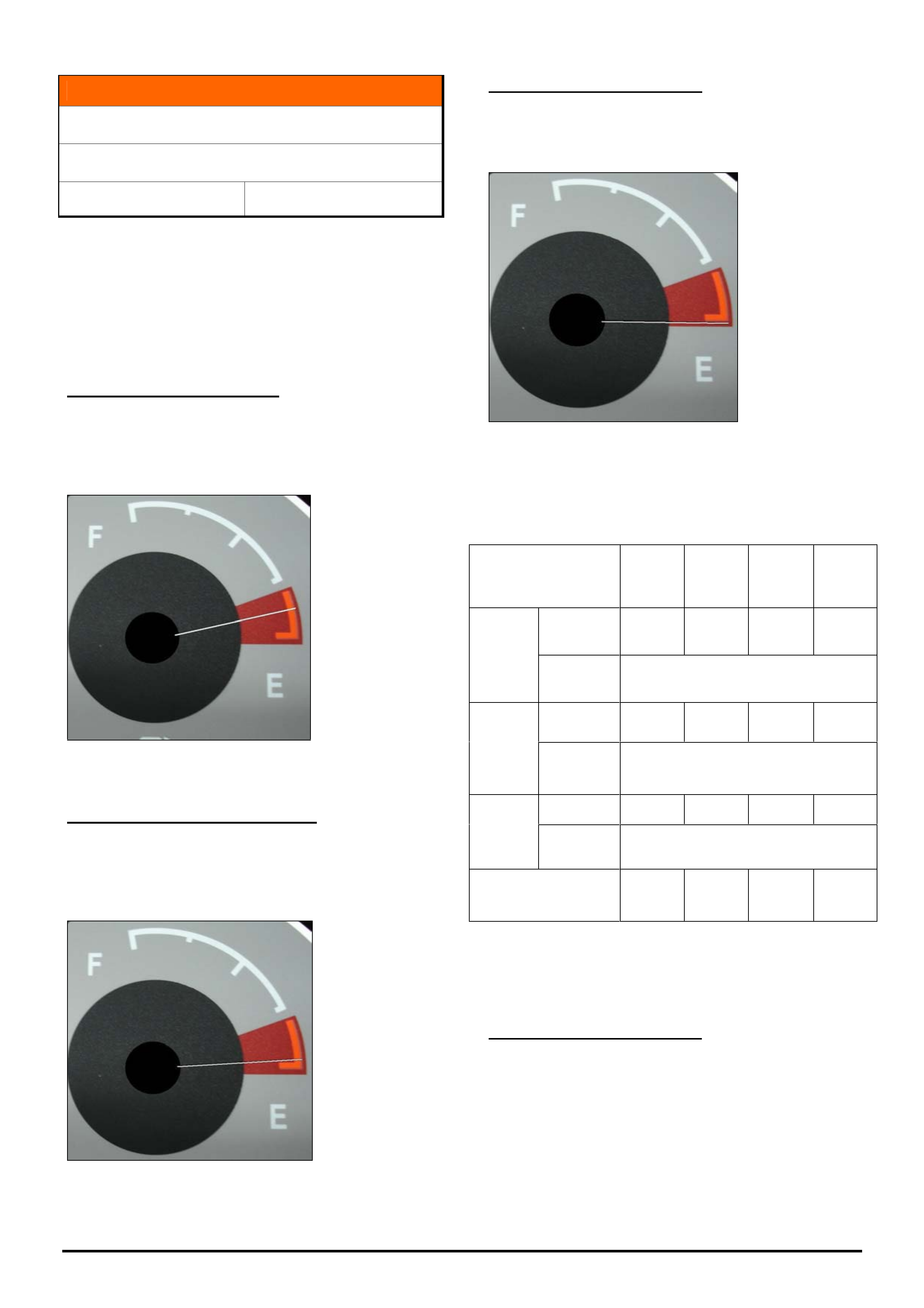
HOLDEN SERVICE TECHLINE __________________________________________________________________________________JUNE, 2005
9
Holden Techlines are written to inform technicians of conditions that may occur on some vehicles, and to provide information that could assist in the
proper service fix of a vehicle. If a condition is described, do not assume the service fix applies to a vehicle or that the vehicle will have that condition.
INFORMATION
Fuel Gauge and Low Fuel Light Operation.
VZ & WL
Group 12 Ref No. TL0891 - 0505
When investigating fuel gauge or low fuel light
operation complaints, explain to the customer the
following system operation characteristics .
Note: The values quoted below are the design intent
and are only appropriate for vehicles without a
recognised problem.
Low Fuel Warning Operation
When the low fuel warning illuminates constantly (and
the audible warning operates) there is approximately 8
to 15 litres of fuel remaining in the tank and the fuel
gauge will indicate the following position.
Note: Some model variants may have different fuel gauge markings
although the needle position will be approximately the same.
Very Low Fuel Warning Operation
When the very low fuel warning illuminates constantly
(and the audible warning operates) there is
approximately 2 to 9 litres of fuel remaining in the tank
and the fuel gauge will indicate the following position.
Note: Some model variants may have different fuel gauge markings
although the needle position will be approximately the same.
Zero DTE Warning Operation
When the trip computer indicates zero DTE there is
approximately 0 to 7 litres of fuel remaining in the tank
and the fuel gauge will indicate the following position.
Note: Some model variants may have different fuel gauge markings
although the needle position will be approximately the same.
Attached below is a table of the approximate fuel tank refill
/ remaining fuel values for each body style at each warning
indication under normal operating conditions.
Coupe
Cab
Chassis
Ute
Sedan
&
Wagon
Vehicle Type
55 to 62
49 to 56
53 to 60
58 to 65
Litres to
Refill
8 to15
Litres
Remaining
Low
Fuel
Warning
61 to 68 55 to 62 59 to 66 64 to 71
Litres to
Refill
2 to 9
Litres
Remaining
Very
Low
Fuel
Warning
63 to 70 57 to 64 61 to 68 66 to 73
Litres to
Refill
7 to 0
Litres
Remaining
Zero
DTE
Warning
70 64
68
73
Litres of Usable Fuel*
Note: All refill values need to be substantiated by a dealership
employee.
*Quoted usable fuel capacities are achieved by using
the recommended refill method detailed below.
Recommended refill method.
The following fuel fill method is recommended.
Step 1. Bowser nozzle at full flow rate until it shuts off
once, then wait approximately 5 seconds.
Step 2. Bowser nozzle at approximately 75% flow rate
until it shuts off for the second time, then wait
approximately 5 seconds.
Step 3. Bowser nozzle at approximately 50% flow rate
until shut off for the third time.
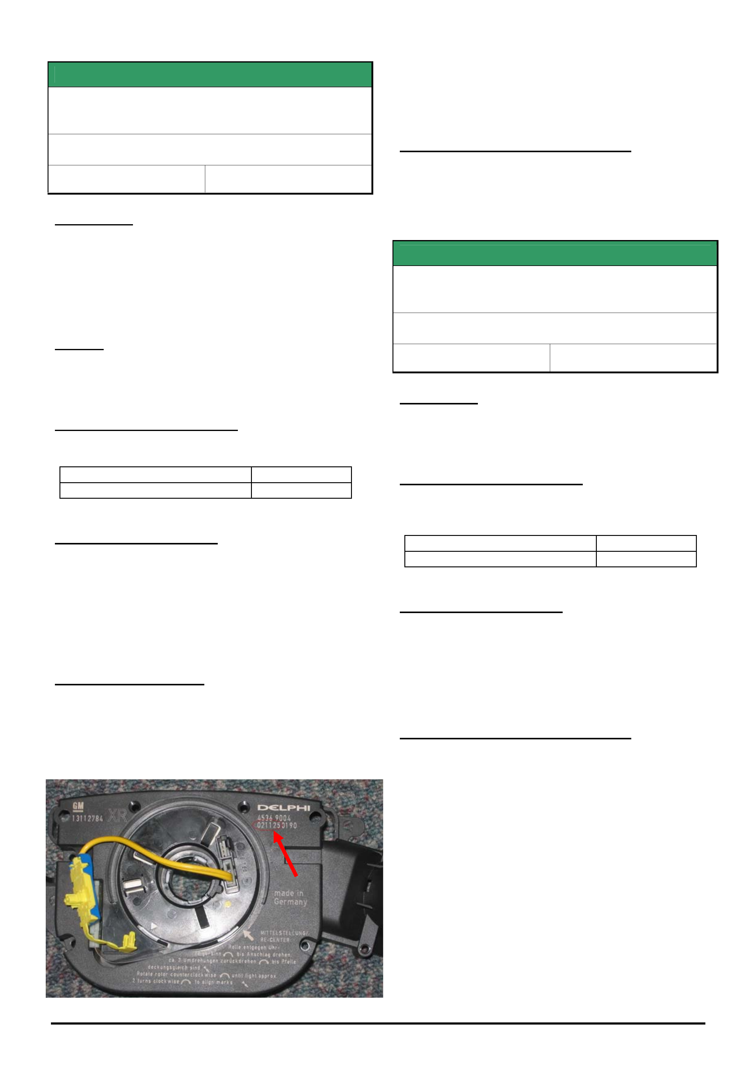
HOLDEN SERVICE TECHLINE __________________________________________________________________________________JUNE, 2005
10
Holden Techlines are written to inform technicians of conditions that may occur on some vehicles, and to provide information that could assist in the
proper service fix of a vehicle. If a condition is described, do not assume the service fix applies to a vehicle or that the vehicle will have that condition.
SERVICE FIX
Cruise control drops out intermittently and
sets DTC B3794
ZC Vectra
Group 12 Ref. No. TL0906 - 0505
CONDITION
Customers may advise that the cruise control drops
out intermittently and will not re-engage until the
ignition is cycled.
When Tech 2 is connected and the vehicle is checked
for DTC’s B3794 may be found.
CAUSE
This condition is caused by a poor connection between
the cruise control stalk and the CIM.
CORRECTION – Production
Revised CIM has been fitted to vehicles from:
ISOVIN: Built Date:
W0L0ZCF6851049996 01/12/2004
CORRECTION – Service
Perform the following:
1. Check for DTC’s using Tech 2.
2. If DTC B3794 is set, perform the standard TIS
diagnosis. If this diagnosis leads to a stalk switch
replacement, replace the CIM also.
PARTS INFORMATION
Revised parts can be identified by the date stamp
located on the top RH corner.
0 4 1 0 3 0 XXXX is Breakpoint for revised parts
(y y mm dd XXXX) i.e. 30/10/2004 or later.
HSPO stock has been culled and only parts
manufactured after the breakpoint will be shipped to
distributors.
WARRANTY CLAIM INFORMATION
Use Labour Times information in Warranty Information
section of current PV SIP CD
SERVICE FIX
Clock In Multi Function Display (MFD) Loses
Time
WK
Group 12 Ref. No. TL0901- 0505
CONDITION
Some customers may complain the clock in their MFD
is losing time.
CORRECTION – Production
A revision to the MFD was introduced into production
as of the following break point.
ISOVIN: Built Date:
**********L328959 7/9/2004
CORRECTION – Service
If a customer presents a vehicle with the above
condition, replace the MFD.
The amount of time lost as stated by the customer
must be recorded on the Repair Order so this can then
be recorded in the 3 Cs of the warranty claim.
WARRANTY CLAIM INFORMATION
Use Labour Times information in Warranty Information
section of current PV SIP CD
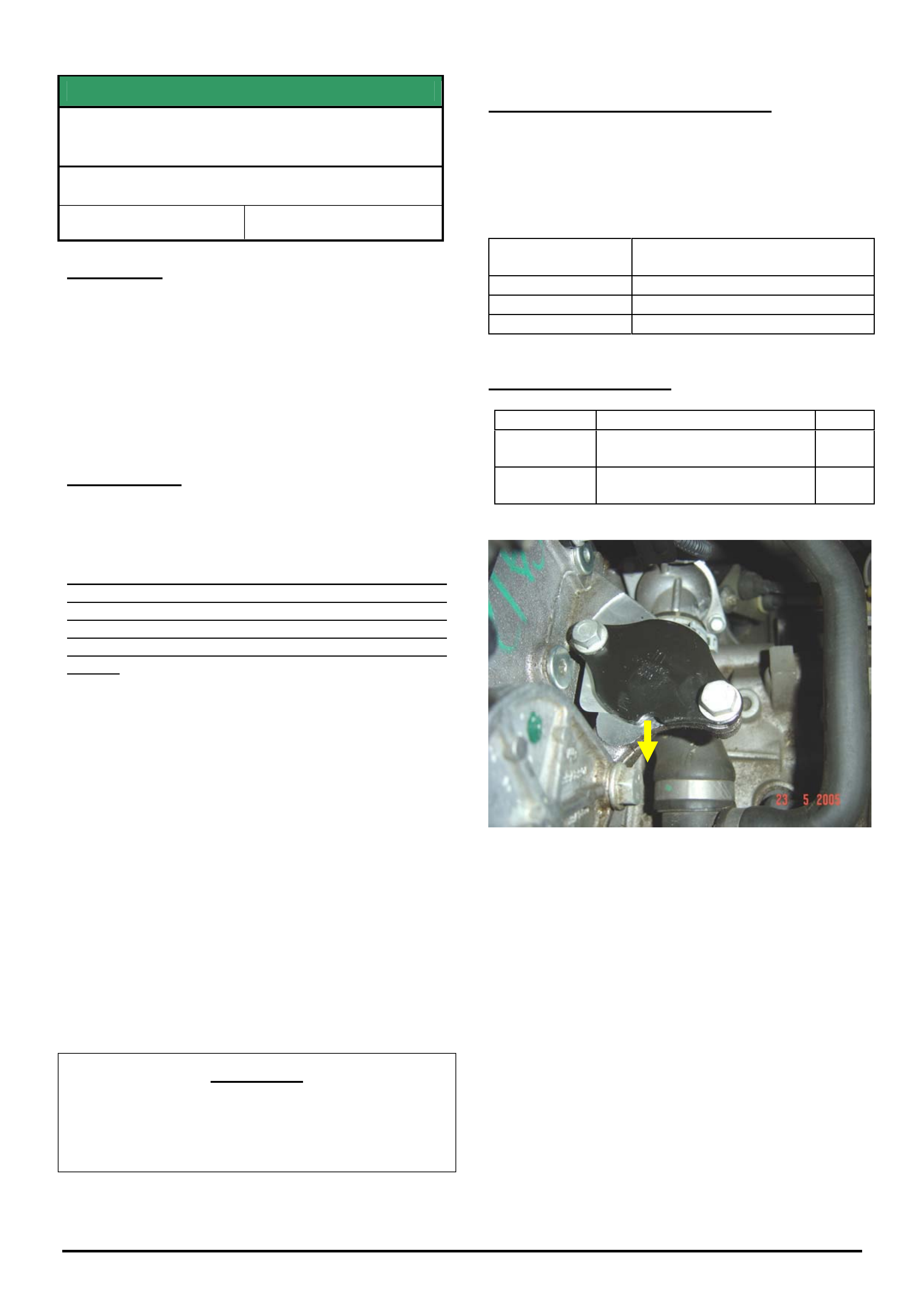
HOLDEN SERVICE TECHLINE __________________________________________________________________________________JUNE, 2005
11
Holden Techlines are written to inform technicians of conditions that may occur on some vehicles, and to provide information that could assist in the
proper service fix of a vehicle. If a condition is described, do not assume the service fix applies to a vehicle or that the vehicle will have that condition.
SERVICE FIX
Cruise Control Accelerates To Set Speed
Too Rapidly.
ZC Vectra with Z22SE engine
Group 12 Ref. No. TL0810- 0504
CONDITION
Some customers may report the following condition
which occurs whilst driving with cruise control set -
After the vehicle loses speed while driving uphill, it
then accelerates too rapidly back to the set speed.
Another customer description may be that when they
press the resume switch to return to the previously set
speed the vehicle accelerates too quickly.
CORRECTION
A revised engine calibration has been developed to
address this condition and is available on TIS 2000
from CD 56 onwards.
IMPORTANT: The revised calibration is only suitable
for vehicles without an EGR valve. If the vehicle is
fitted with an EGR valve (Engine No. prior to
Z22SE11293531), it will need to be deleted as per the
following procedure prior to SPS programming the
vehicle.
Procedure for EGR Deletion .
1. Remove EGR valve. (Refer TIS)
2. Close exhaust gas recirculation port with a cover
plate (part No. 24575592) and new gasket (part No.
12570863). The groove on the plate has to point in the
direction of the radiator and the plate labelling facing
upwards.
Torque the two cover plate attaching bolts to 23 Nm.
3. Fix the EGR wiring harness connector with a cable
strap. (face connector opening towards rear).
4. Program ECU via the standard Service
Programming System (SPS) method using TIS 2000,
CD 56 or later (select without EGR).
IMPORTANT
Always ensure the latest Tech 2 software from TIS
is loaded into your Tech 2 before attempting any
reprogramming using SPS method.
WARRANTY CLAIM INFORMATION
For SPS programming only, use the standard labour
times information in Warranty Information section of
current PV SIP CD.
If the vehicle has an EGR valve which needs to be
removed, use the following information.
Description Remove EGR valve, add cover
plate, and reprogram ECU
Labour Op. No. J000776
Time 0.6 hr
Failure Code J0057 registers incorrectly
PARTS INFORMATION
Part No.: Partfinder Name Qty:
24575592 Cover plate- EGR valve
opening
1
12570863 Gasket - EGR valve to cyl
head
1
Figure 1. Shows EGR cover plate with groove facing
towards front of vehicle.
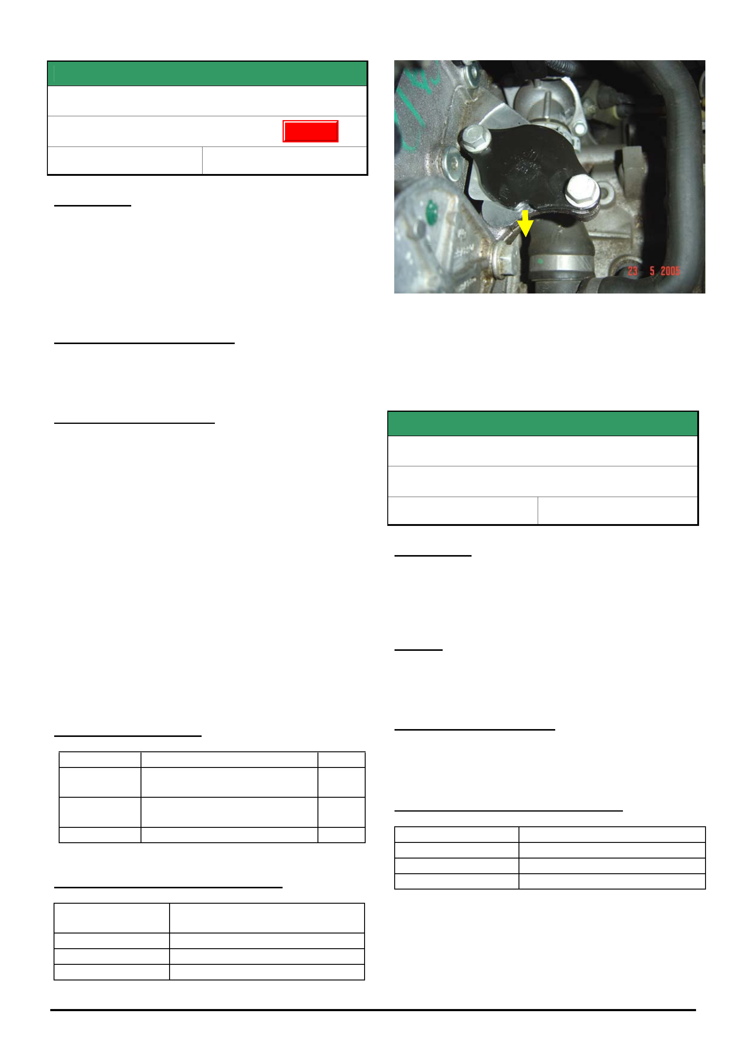
HOLDEN SERVICE TECHLINE __________________________________________________________________________________JUNE, 2005
12
Holden Techlines are written to inform technicians of conditions that may occur on some vehicles, and to provide information that could assist in the
proper service fix of a vehicle. If a condition is described, do not assume the service fix applies to a vehicle or that the vehicle will have that condition.
SERVICE FIX
EGR Malfunction
ZC Vectra with Z22SE engine
Group 6C Ref. No. TL0919 - 0505
CONDITION
Drivers may report that their vehicle runs rough or
lacks power.
The telltale light comes on and P1404 DTC is set
(EGR valve sticking).
Dealers have been responding to these conditions by
fitting a new EGR valve.
CORRECTION – Production
The EGR-valve was removed in production (during
Model Year 2004) from Engine No. Z22SE11293531
CORRECTION – Service
On complaint vehicles where diagnosis finds that an
EGR valve is faulty, it should not be renewed but
removed altogether as per the following procedure.
Procedure.
1. Close exhaust gas recirculation port with a cover
plate (Part No. 24575592). Replace gasket when doing
so. (Part No. 12570863). The groove on the plate has
to point in the direction of the radiator with the plate
labeling facing upwards.
2. Fix the superfluous wiring harness connector with a
cable strap (face connector opening to rear of vehicle).
3. Program ECU via the standard Service
Programming System (SPS) method using TIS 2000,
CD 56 or later (select without EGR).
PARTS INFORMATION
Part No.: Partfinder Name Qty:
24575592 Cover plate- EGR valve
opening
1
12570863 Gasket - EGR valve to cyl
head
1
12569559 EGR valve 1
WARRANTY CLAIM INFORMATION
Description Remove EGR valve, add cover
plate, and reprogram ECU
Labour Op. No. J000776
Time 0.6 hr
Failure Code J0057 registers incorrectly
Figure 1. Shows EGR cover plate with groove facing
towards front of vehicle.
SERVICE FIX
A/T Shift Harshness
WK V8
Group 7B Ref. No. TL0933- 0505
CONDITION
Some customers may complain of shift harshness
during:
1-2, 2-3 upshifts, 3-2 downshift in ‘normal’ mode;
1-2 and 2-3 upshifts in ‘Power’ mode.
CAUSE
Sensitivity of some vehicle powertrains to the
production calibration.
CORRECTION – Service
Should a customer complain of shift harshness as
described above, reprogram with calibration 92183020
available from TIS CD 58 onward.
WARRANTY CLAIM INFORMATION
Description WK V8 A/T Shift Reprogram
Labour Op. No. K000303
Time 0.3 hr
Failure Code NOW K0043 Shifts Hard
Update
HOLDEN SERVICE TECHLINE __________________________________________________________________________________JUNE, 2005
13
Holden Techlines are written to inform technicians of conditions that may occur on some vehicles, and to provide information that could assist in the
proper service fix of a vehicle. If a condition is described, do not assume the service fix applies to a vehicle or that the vehicle will have that condition.
SERVICE FIX
High Idle Speed with A/C On
VZ Gen III with M/T (excluding cab chassis
variants)
Group 6C Ref. No. TL0932- 0505
CONDITION
Customer may complain that when the A/C is turned
on, the engine intermittently has a high idle speed, that
will not drop to normal idle speed for some seconds
after throttle is closed (IE: on deceleration or between
gear changes).
CAUSE
Powertrain management system calibration incorrectly
compensates for A/C compressor loading during
certain air flow conditions.
CORRECTION – Production
Revised calibrations with revised control parameters
have been installed in vehicles from:
Sedan (Cal # 92182878):
ISOVIN: Built Date:
6G1ZK54F85L389596 17/01/05
Coupe (Cal # 92182884):
ISOVIN: Built Date:
6G1ZX14F95L389519 20/01/05
Utility (Cal # 92182880):
ISOVIN: Built Date:
6G1ZK42F05L390626 21/01/05
CORRECTION – Service
If the calibration number does not match the revised
calibration (as in breakpoints above) - reprogram using
TIS CD 59 or later.
WARRANTY CLAIM INFORMATION
Description VZ V8 M/T Idle Reprogram
Labour Op. No. J000773
Time 0.3 hr
Failure Code NOW J0057
DIAGNOSIS HINT
DTC U0155 set in Engine ECU
VZ & WL V6
(GROUP 6C) TL0923-0505
PROBLEM DESCRIPTION
Vehicles may log DTC (diagnostic trouble code)
U0155, “CANbus no communication with gateway” in
the engine ECU. Many dealers are following the
diagnostic procedure in SIP believing this DTC is
causing a vehicle concern.
Engineering is currently investigating the cause of this
DTC and have advised that this DTC does not cause
any vehicle concerns.
If confronted with a vehicle that has this DTC, be
aware that this should not be the cause for any
concern and should be ignored.
Do not replace any parts for this DTC.
INFORMATION
Searching for Techlines, Dealer Letters etc. on
Holden Lionheart (Portal)
(GROUP OB) TL0921-0504
This Techline describes two methods for locating
Techlines, Dealer Letters, Campaign Bulletins etc. on
Holden Lionheart.
• CONVENTIONAL method
• SEARCH ENGINE method.
The CONVENTIONAL method is similar to looking up
information in a text book. You commence by looking
in the Table Of Contents at the front of the book then
looking up the page reference then scanning down the
page until you find the section you’re looking for.
The “SEARCH ENGINE” method involves entering
your search criteria in a Search window and then
letting the search engine find the techlines
automatically.
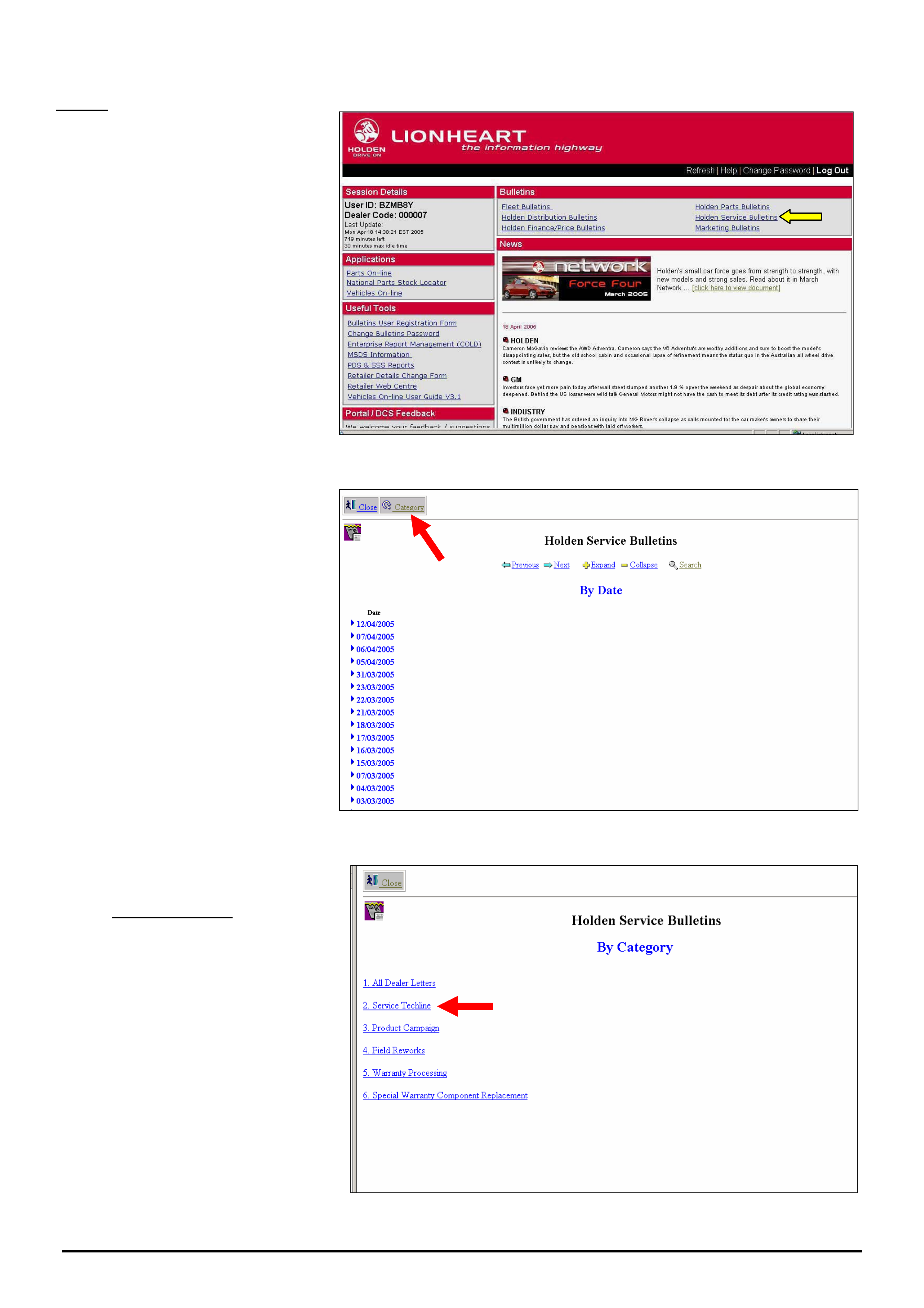
HOLDEN SERVICE TECHLINE __________________________________________________________________________________JUNE, 2005
14
Holden Techlines are written to inform technicians of conditions that may occur on some vehicles, and to provide information that could assist in the
proper service fix of a vehicle. If a condition is described, do not assume the service fix applies to a vehicle or that the vehicle will have that condition.
START
1. After logging onto Holden
Lionheart select “Holden Service
Bulletins” as indicated by yellow
arrow.
Figure 1.
2. The next screen to appear shows
all items in the Holden Service
Bulletin Database arranged by Date.
The most recent items are on the top
of the list. To view the item, click on
the ►next to the date.
HINT: Check this screen everyday
to view the latest information
issued by Holden Service
Department.
If you select the “Category” button as
indicated by red arrow, the screen
shown in Figure 3 will appear.
Figure 2
3. In this example we will show how
to locate a Service Techline. Now
select “Service Techline” from the list
shown.
The next screen to appear is shown
in Figure 4 on next page.
Figure 3.
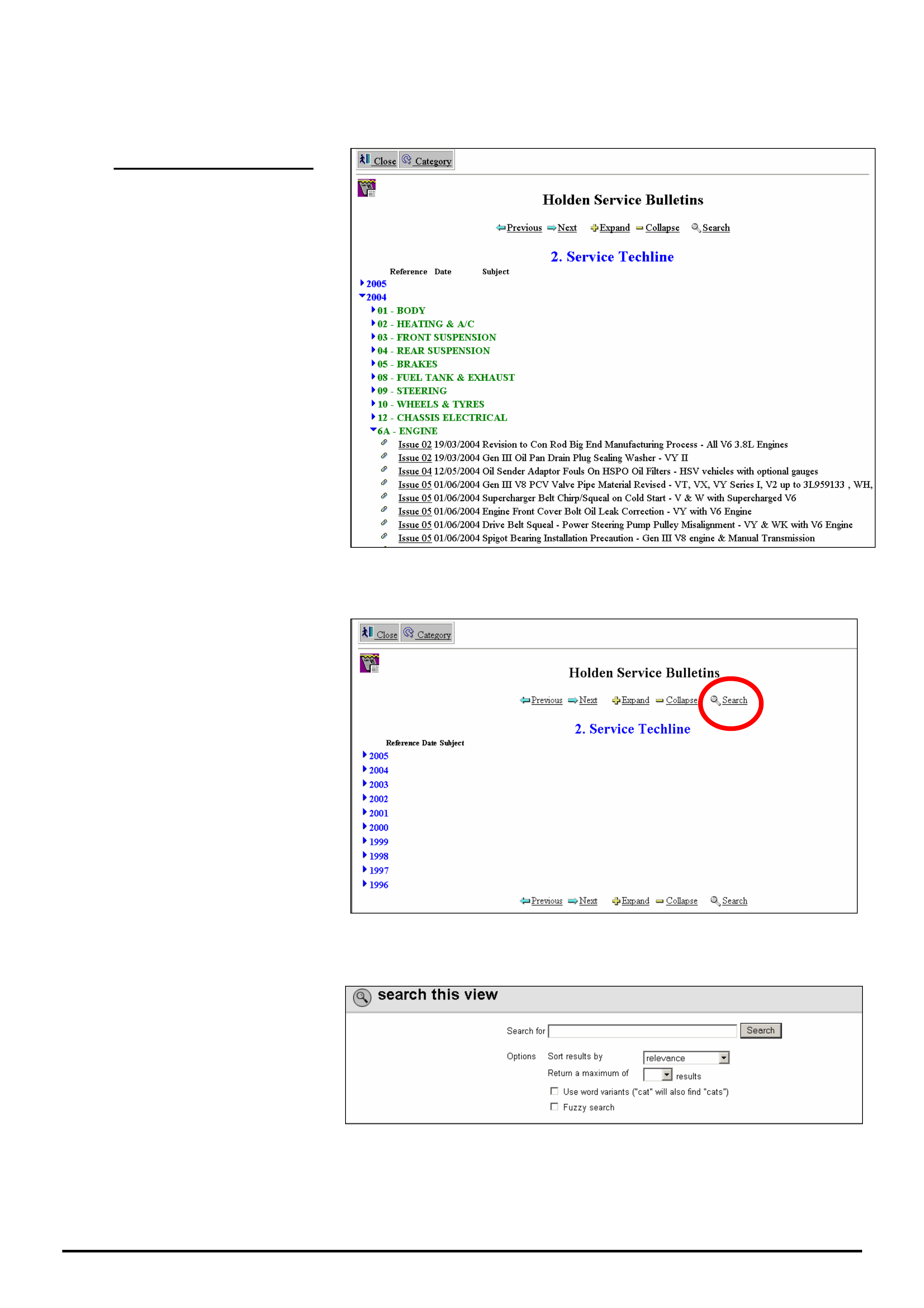
HOLDEN SERVICE TECHLINE __________________________________________________________________________________JUNE, 2005
15
Holden Techlines are written to inform technicians of conditions that may occur on some vehicles, and to provide information that could assist in the
proper service fix of a vehicle. If a condition is described, do not assume the service fix applies to a vehicle or that the vehicle will have that condition.
Following is a description of how to locate information by the conventional method or by using the search
function.
4 (A). Conventional Method.
As an example, we will look for a
techline on
V
Y V6 oil leak from
engine front cover.
Choosing the right year and the right
Group to look in are the keys to
finding a techline quickly.
As VY was produced from 2002 to
2004 you should commence looking
in 2004. Choose group 6A – Engine
and look through list of techlines until
you find the right one, which in this
example was published in Issue
05/2004
The drawback with this
“Conventional” method is knowing
which year and group to look in. It
can also be time consuming
scanning through long lists of
techlines.
Figure 4
4 (B). SEARCH-Function
Method
From the screen shown in Figure 5,
click on the “Search” key. This will
bring up the screen shown in Figure
6.
Figure 5
This is the search screen we use for
entering our search criteria (i.e. an
accurate summary of what we are
searching for)
Figure 6
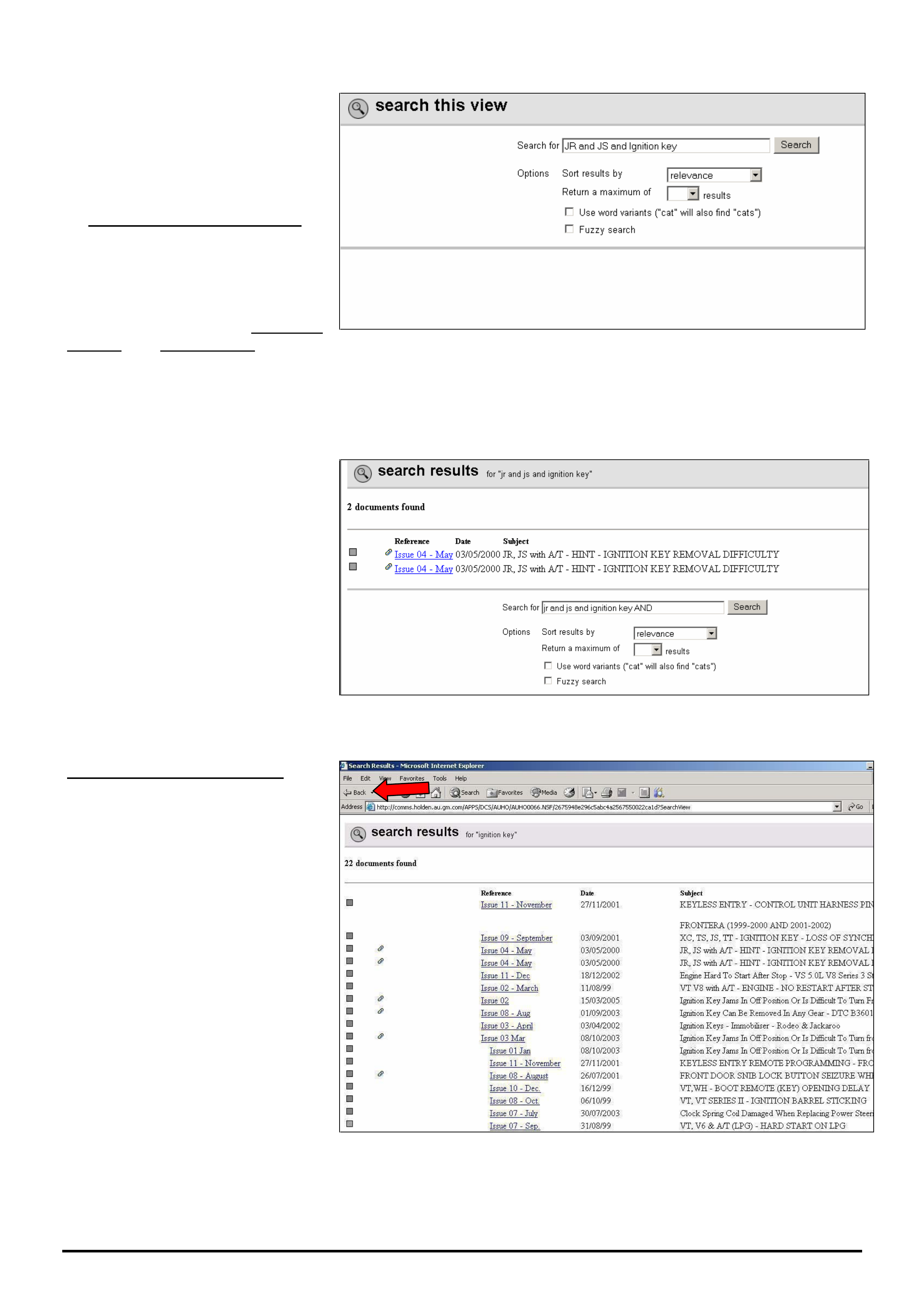
HOLDEN SERVICE TECHLINE __________________________________________________________________________________JUNE, 2005
16
Holden Techlines are written to inform technicians of conditions that may occur on some vehicles, and to provide information that could assist in the
proper service fix of a vehicle. If a condition is described, do not assume the service fix applies to a vehicle or that the vehicle will have that condition.
As an example we will search for
techlines related to JR & JS Vectra
Ignition Barrel Jamming.
In the “Search for” window, type in
the following “search string”.
“JR and JS and Ignition key”.
Don’t touch the next 2 boxes titled
“Sort results by” or “Return a
maximum of”.
Tick the last 2 boxes i.e. Use Word
variants and Fuzzy search. Refer to
later explanations of these terms.
Now click the “Search” button.
Figure 7
The search result is 2 documents as
shown in Figure 8.
Click on the hot-key section (in blue)
to view the techlines.
Figure 8.
Defining Your Search Criteria
If we had entered only “ignition key”
in the search window the search
engine would have located 22
techlines as shown in Figure 8.
If we had entered only “ignition”, the
search engine would have located
85 techlines.
So you can see the importance of
defining your search criteria as
accurately as possible so you don’t
end up with huge numbers of items
to read through.
Rule of thumb: the less information
in the “search window” the more
information comes back.
If at anytime you wish to go back to
the “Search” function press the
“Back” arrow in the top left side of
the toolbar. Refer red arrow.
Figure 9.
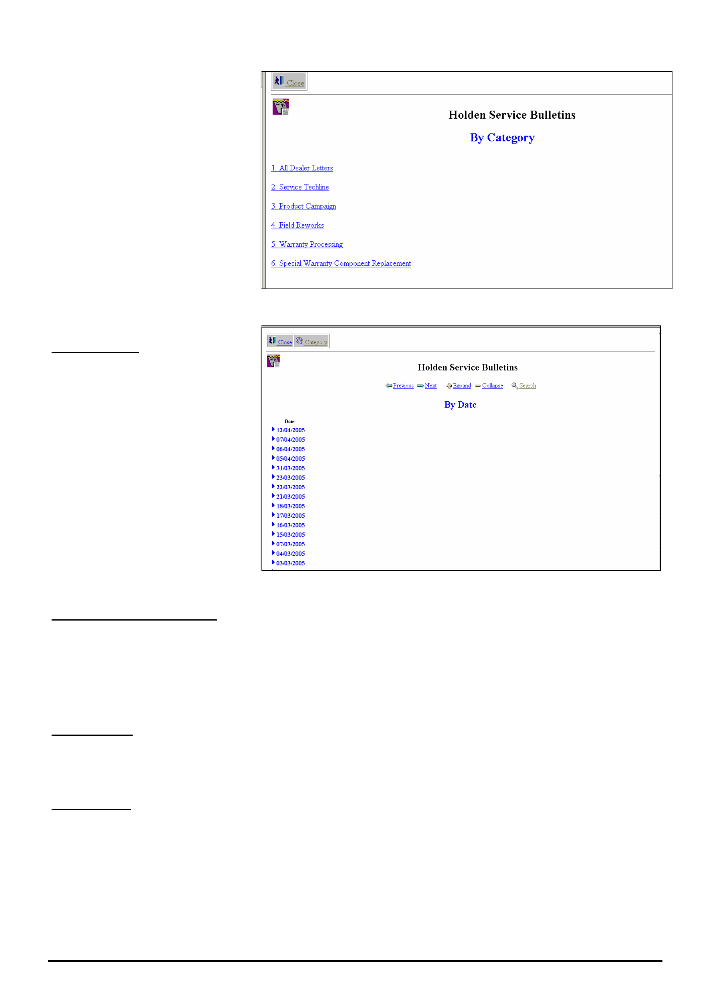
HOLDEN SERVICE TECHLINE __________________________________________________________________________________JUNE, 2005
17
Holden Techlines are written to inform technicians of conditions that may occur on some vehicles, and to provide information that could assist in the
proper service fix of a vehicle. If a condition is described, do not assume the service fix applies to a vehicle or that the vehicle will have that condition.
To search for a Dealer Letter,
Campaign Bulletin, Field rework or
Warranty Bulletin, use the same
procedure as that described for a
Service Techline.
IMPORTANT: You must first select
the category you want from the
Category screen (Figure 10) before
proceeding with search.
Figure 10.
General Search.
To find ALL published information on
a subject, select “Search” from
screen shown in Figure11.
As an example, enter “Daewoo” in
the search field
This “search” will give you everything
that contains the word “Daewoo” .eg.
Dealer letters, Techlines, Recalls,
Warranty etc.
Figure 11
General Notes On Searching.
• If you perform a search and the results are not what you were looking for; to conduct another search, you will
need to hit the “← Back arrow” in the Microsoft Internet Explorer menu at top left of page. This will bring up a
new search window that you can enter new search criteria into after deleting the previous search criteria.
• The search engine cannot search any “attached” files such as Word, Excel, Pdf, on Holdens database. It can only
search for words that appear on the viewing page for each individual item.
Word Variants
If you tick this box in the search panel, and type in “cat” in the “Search For” window, the search engine will find every
word that has cat in it, eg. catalytic, category, cats, etc. This is useful if you cannot remember the exact spelling of a
word or you forget the s when the word is plural.
Fuzzy Search.
EXAMPLE 1. Search for techlines with DTC P0335 in the Subject title.
If you accidentally type in DTCP0335 without a space between C and P, and do a Fuzzy search, the search engine
will still bring up all techlines containing “DTC P0355”.
EXAMPLE 2. Search for techlines containing 4JX1 in the subject title.
If you accidentally type in 4JX, a fuzzy search will still find all techlines with 4JX1 in the title. This feature doesn’t
seem to work if you forget to enter the first letter. in this example, doing a Fuzzy search on JX1 will not find anything.
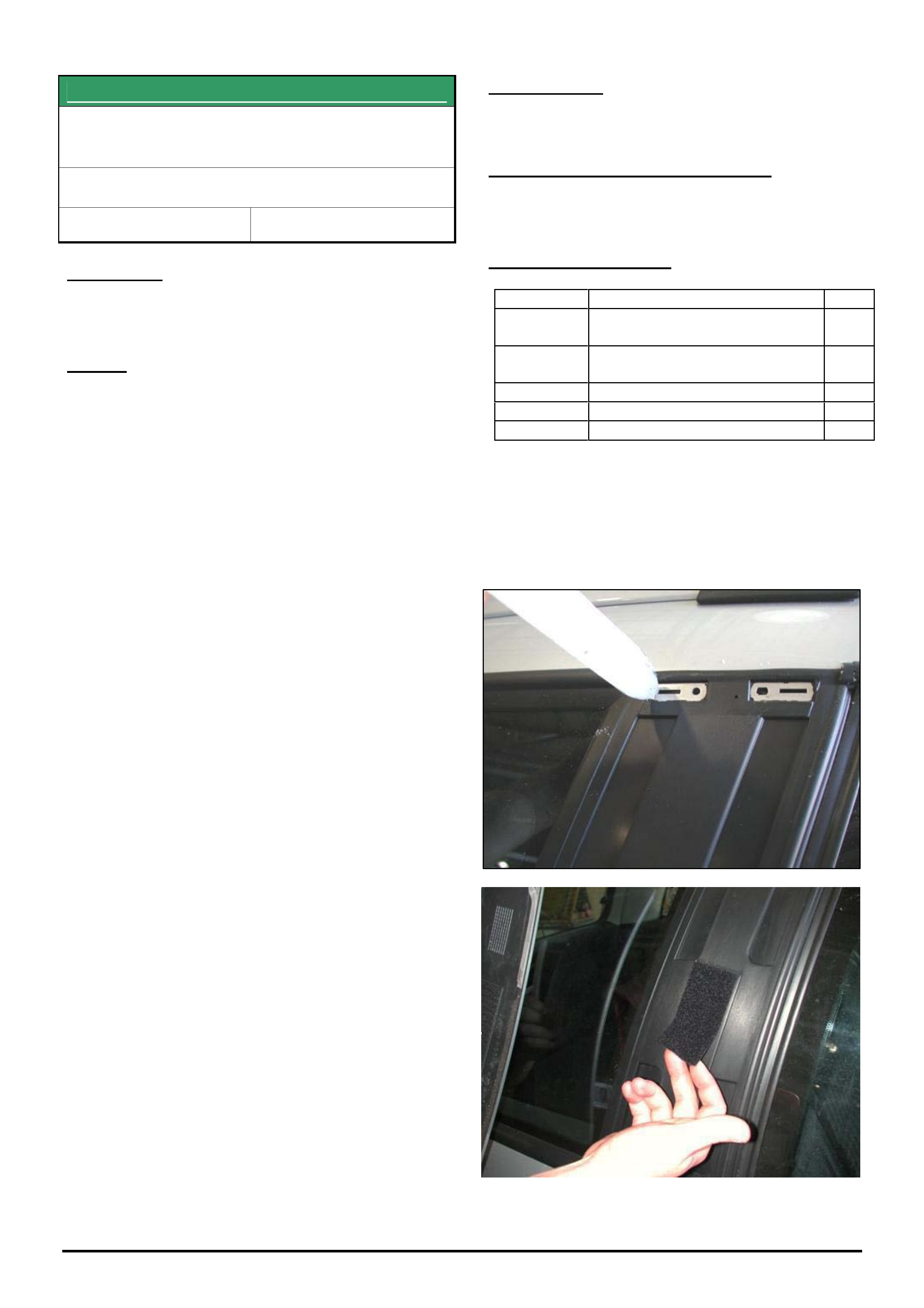
HOLDEN SERVICE TECHLINE __________________________________________________________________________________JUNE, 2005
18
Holden Techlines are written to inform technicians of conditions that may occur on some vehicles, and to provide information that could assist in the
proper service fix of a vehicle. If a condition is described, do not assume the service fix applies to a vehicle or that the vehicle will have that condition.
SERVICE FI
X
C Pillar Exterior Moulding (Applique)
Detaches
VY & VZ Adventra
Group 1 Ref. No. TL0911 - 0505
CONDITION
Left hand or Right hand C Pillar moulding comes loose
or detaches from the rear quarter window.
CAUSE
Inadequate adhesion.
CORRECTION
Reattach C pillar moulding (Appliqué) as per following
attached instructions.
WARRANTY CLAIM INFORMATION
Use Labour Times information in Warranty Information
section of current PV SIP CD
PARTS INFORMATION
Part No.: Partfinder Name Qty:
92120547 Applique –quarter window rear
RH
1
92120548 Applique –quarter window rear
LH
1
92149056 Velcro patch 1
92146444 Urethane 300ml cartridge 1
92145403 Primer 1
____________________________________________________________________________________________
PROCEDURE.
Step 1 - Remove Applique from vehicle (if still attached). Order replacement appliqué if damaged.
Step 2 - Remove any broken clips from the upper and
lower Applique mounting points.
If there is any damage to the rear quarter window
assembly (except for a loose or damaged velcro
patch), replace the window with the appropriate part
number. Check when window arrives that velcro patch
is firmly attached to the centre of the pillar section.
Step 3a - If window assembly does not need
replacing, check for Velcro patch adhesion to the
window assembly. If Velcro patch is missing, order
92149056 from HSPO and attach as per steps 3b to
3d. If Velcro patch is loose, remove and reattach as
per steps 3b to 3d.
If Velcro patch is firmly attached, move to step 4.
Step 3b - Remove velcro patch. Clean surface beneath patch by cleaning with methylated spirits or prepsol and a
clean lint free cloth.
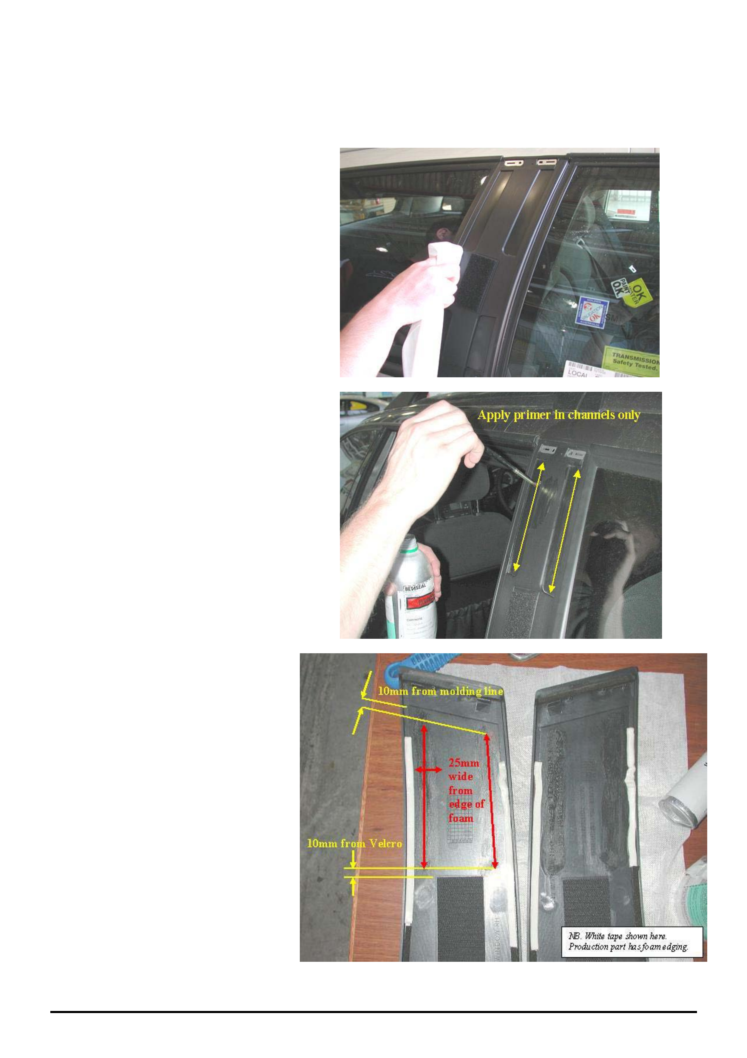
HOLDEN SERVICE TECHLINE __________________________________________________________________________________JUNE, 2005
19
Holden Techlines are written to inform technicians of conditions that may occur on some vehicles, and to provide information that could assist in the
proper service fix of a vehicle. If a condition is described, do not assume the service fix applies to a vehicle or that the vehicle will have that condition.
Step 3c - On the cleaned surface apply a coat of primer 92145403. Allow surface to dry for a minimum of 10
minutes.
Step 3d - Remove adhesive tape backing from Velcro patch and attach to window moulding within the rectangular
marked section. Apply pressure to the entire surface of the Velcro to ensure adhesion is uniform.
Step 4 - Clean upper two grooves in
window assembly using methylated spirits
or prepsol and a lint free cloth.
Step 5 – Apply primer 92145403, to the
two upper grooves in window assembly.
Allow 10 minutes to dry.
Step 6 - On new Applique(s) - clean upper
sections indicated in photograph opposite
with methylated spirits or prepsol and a lint
free cloth.
Step 7 – Now apply primer 92145403, to
the upper two sections just cleaned in step
6. Allow 10 minutes to dry.
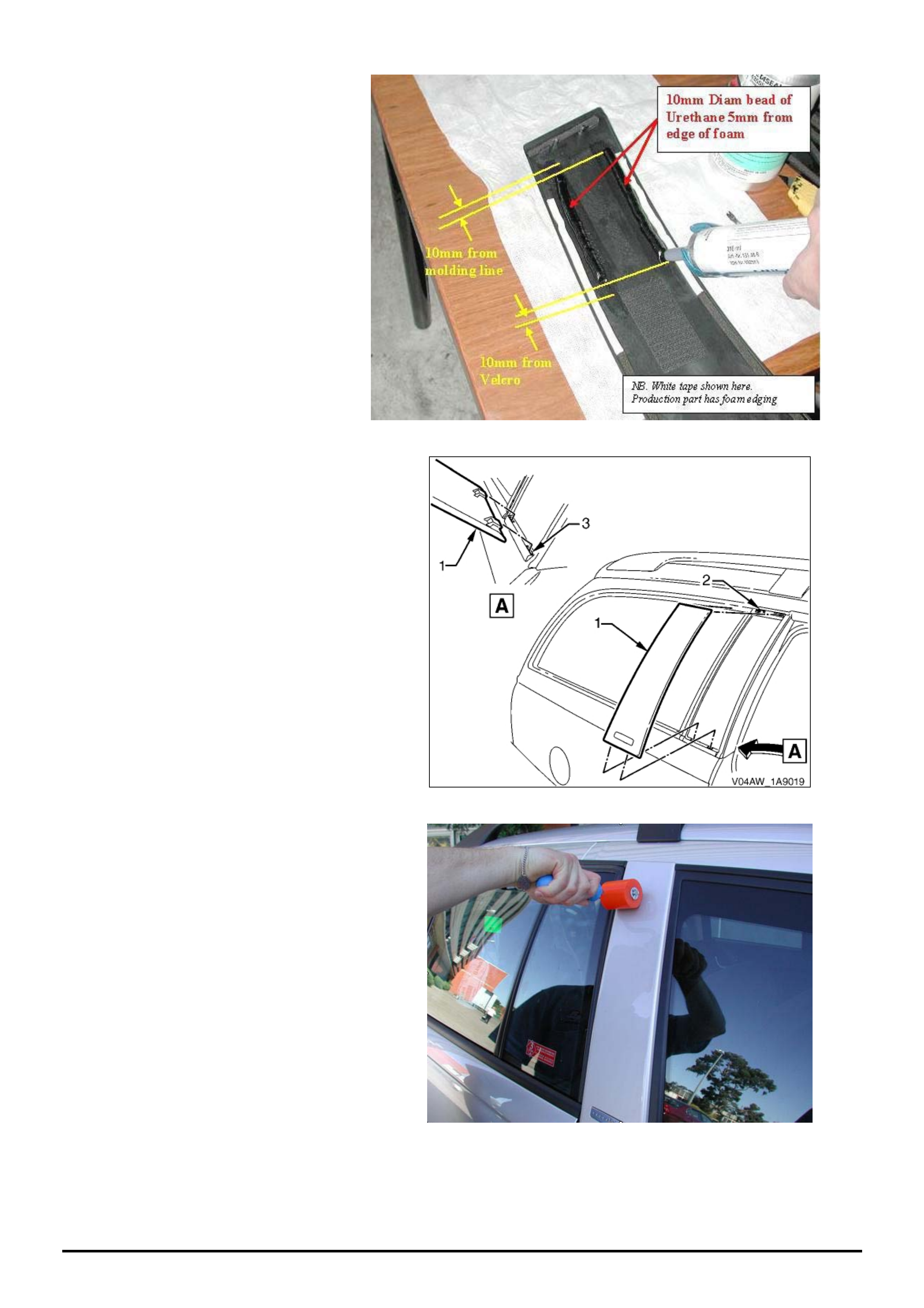
HOLDEN SERVICE TECHLINE __________________________________________________________________________________JUNE, 2005
20
Holden Techlines are written to inform technicians of conditions that may occur on some vehicles, and to provide information that could assist in the
proper service fix of a vehicle. If a condition is described, do not assume the service fix applies to a vehicle or that the vehicle will have that condition.
Step 8 - Using urethane p/n 92146444,
apply a 10 mm bead 5mm from edge of
foam as shown in photograph..
Step 9 - Install new applique (as per
procedure in Passenger SIP) by first
sliding bottom edge of appliqué (1) into the
holes (3) then pushing top edge into
retaining holes (2).
Step 10 – Using a soft roller, roll top edges
of applique to ensure the Velcro tape and
the urethane have contact with glass
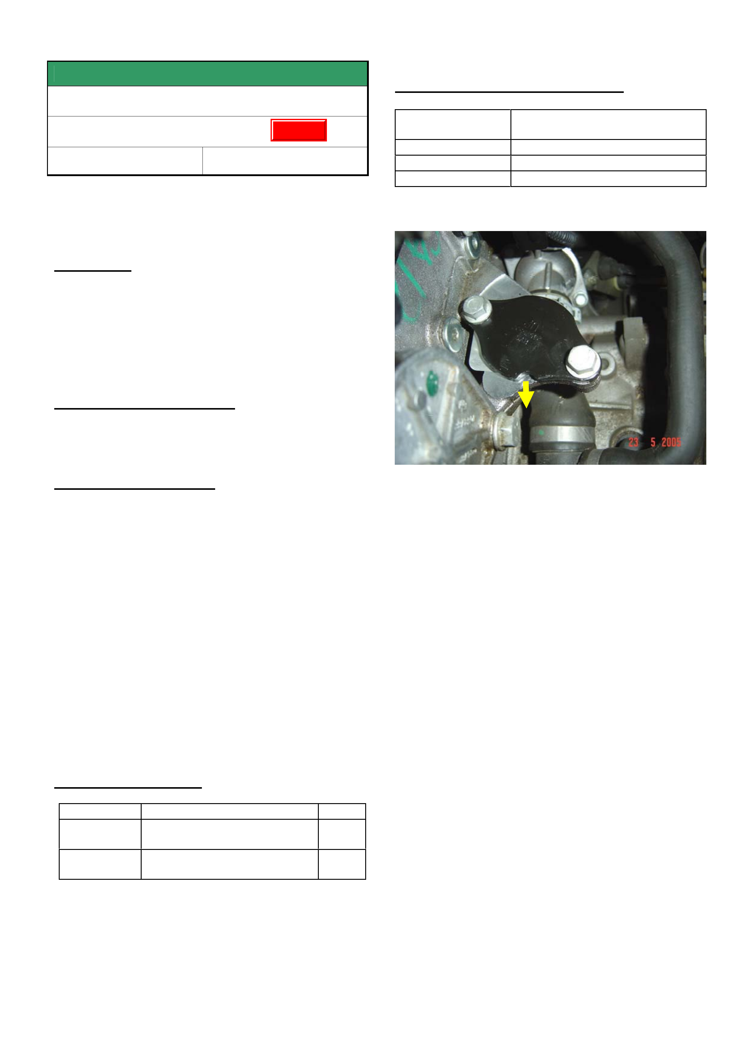
SERVICE FIX
EGR Malfunction
ZC, and Z22SE engine
Group 6C Ref. No. TL0919B - 0507
This Techline supercedes the previous one in Issue 5,
June, 2005. It is revised by removing the EGR Valve
from the Parts Information as it is NOT required.
CONDITION
Drivers may report that their vehicle runs rough or
lacks power.
The telltale light comes on and P1404 DTC is set
(EGR valve stuck).
Dealers are currently responding to these conditions
by fitting a new EGR valve.
CORRECTION – Production
The EGR-valve was removed in production (during
Model Year 2004) from Engine No. Z22SE11293531
CORRECTION – Service
On complaint vehicles where diagnosis finds that an
EGR valve is faulty, it should not be renewed but
removed altogether as per the following procedure.
Procedure.
1. Close exhaust gas recirculation port with a cover
plate (Part No. 24575592). Replace gasket when doing
so. (Part No. 12570863). The groove on the plate has
to point in the direction of the radiator with the plate
labeling facing upwards.
2. Fix the superfluous wiring harness connector with a
cable strap (face connector opening to rear of vehicle).
3. Program ECU with SPS as of TIS 2000, CD 56
(select without EGR).
PARTS INFORMATION
Part No.: Partfinder Name Qty:
24575592 Cover plate- EGR valve
opening
1
12570863 Gasket - EGR valve to cyl
head
1
WARRANTY CLAIM INFORMATION
Description Remove EGR valve, add cover
plate, and reprogram ECU
Labour Op. No. J000776
Time 0.6 hr
Failure Code J0057 registers incorrectly
Figure 1. Shows EGR cover plate with groove facing
towards front of vehicle.
Update
HOLDEN SERVICE TECHLINE __________________________________________________________________________________JULY, 2005
5
Holden Techlines are written to inform technicians of conditions that may occur on some vehicles, and to provide information that could assist in the
proper service fix of a vehicle. If a condition is described, do not assume the service fix applies to a vehicle or that the vehicle will have that condition.
INFORMATION
DTC’s U0415 and U2108 set in ECM and PIM
VZ Cab Chassis, Crewman, and Ute without
ABS
Group 8 Ref. No. TL0954- 0506
CONDITION
The following DTC’S may be current in the Engine
ECU (Electronic Control Unit) and PIM (Powertrain
Interface Module)
• DTC U0415 - Invalid data from ABS
• DTC U2108 - CANBUS no communication with ABS.
No warning lights are displayed in the instruments.
CAUSE
These DTC’s are characteristic for base model cab
chassis/Crewman and Utility vehicles which ARE
NOT fitted with ABS.
CORRECTION
DO NOT replace engine ECU’s or PIM’s for these
fault codes. There is no fault and no correction
procedure is required
Holden PV SIP will be updated to highlight the fact
that DTC’s U0415 and U2108 are characteristic on
the above models which are not fitted with ABS.
SERVICE FIX
Holden Assist Advise Customer of Invalid
Location Information
VY / V2II & III / WK / WL
Group 12 Ref. No. TL0953-0506
CONDITION
Customers may report that Holden Assist has advised
that they are receiving invalid or no location
information from their vehicle intermittently.
CORRECTION - Production
Vehicles were built with revised software from:
ISOVIN: Build Date:
6G1******* L426688 06/04/05
CORRECTION - Service
1. Using Tech 2 review the location information in
the Telematics module GPS data list by selecting
the following,
Diagnostic/Model Year/Vehicle Type/Body/Telematics
Module/Data Display/Global Positioning System
2. (a) If there is no location information displayed in
the data list refer to PV SIP Section 12 K / 4.4
Strategy Based Diagnostics.
(b) If the location information is displayed,
reprogram the Telematics module via the
standard SPS process using TIS 2000 version 62
or later.
Note: Check that the VIN number is correct. If VIN is
incorrect, you will require a Change Over module from
Australian Arrow, which can be obtained via the
standard Change Over process.
The Telematics module will automatically be left in
SERVICE mode after completing the programming
process.
Note: The vehicle should be returned to the customer
with the Telematics system in the same operating
mode, in which they left it. If this is not known, it
should be left in SERVICE mode.
WARRANTY CLAIM INFORMATION
Description Reprogramming Telematics Module
Labour Op. No. N000438
Time 0.3 hr
Failure Code 57 Registers Incorrectly
HOLDEN SERVICE TECHLINE __________________________________________________________________________________JULY, 2005
8
Holden Techlines are written to inform technicians of conditions that may occur on some vehicles, and to provide information that could assist in the
proper service fix of a vehicle. If a condition is described, do not assume the service fix applies to a vehicle or that the vehicle will have that condition.
SERVICE FIX
Fuel Gauge Conservative Refill (High
Reserve)
VZ V6 Ute
Group 12 Ref. No. TL0952 - 0506
CONDITION
Reports have been received of not being able to add
enough fuel into the tank once the low fuel warning is
displayed.
Note- Refer to Techline TL0891-0505 “Fuel Gauge
and Low Fuel Light Operation” published in issue 5,
June 2005.
CAUSE
The fuel gauge section of the Engine Control Module
calibration.
CORRECTION – Production
A revised fuel gauge calibration was programmed into
vehicles in production from the following breakpoint:
ISOVIN: Built Date:
**********L444651 18/05/2005
CORRECTION – Service
To rectify this condition it will be necessary to:
1. reprogram the Engine ECU via the standard SPS
process using TIS 2000 version 62 or later and
2. reprogram the instrument cluster fuel gauge
calibration using Tech 2 with software version
14.1 or later.
WARRANTY CLAIM INFORMATION
Description Reprogram PCM &
Instrument cluster
Labour Op. No. N000481
Time 0.5 hr
Failure Code N0057 Registers incorrectly

HOLDEN SERVICE TECHLINE __________________________________________________________________________________JULY, 2005
9
Holden Techlines are written to inform technicians of conditions that may occur on some vehicles, and to provide information that could assist in the
proper service fix of a vehicle. If a condition is described, do not assume the service fix applies to a vehicle or that the vehicle will have that condition.
DIAGNOSIS HINT
ESP Early Intervention
VZ & WL with ESP
Group 5 Ref. No. TL0944 - 0506
CONDITION
Customer complains that the ESP is activating
unnecessarily. A buzz from the ABS module is heard
during this event.
The above condition may be caused by incorrect
centralisation of the steering gear where the SAS
(Steering Angle Sensor) is calibrated to this “off
central” point.
RECOMMENDED ACTION
Summary: Centralise the steering gear, adjust toe
and steering wheel to new central point and
recalibrate the steering angle sensor (SAS). The
relevant procedures are as follows.
1. Verify the position of the steering gear using tech 2. In
the ABS data list monitor the SAS position from the
zero (0°) position. With the engine idling turn the
steering wheel to lock one side and note the reading
(The steering wheel will have to be turned very firmly
against the rack lock stop to get the maximum travel
reading) . Turn the wheel back to centre (0°) and now
turn wheel to lock in the other direction and note the
reading. The difference from side to side can be no
more than 8°. Total travel from lock to lock should
add up to approximately 1000°. Note the total travel
reading that can consistently be achieved.
2. If the reading difference from side to side is greater
than 8°, proceed to locate the steering gear central
point and recalibrate the SAS as follows.
3. Centralise the steering gear position. This can be
done with tech 2, once again monitoring the SAS
reading. Using the above noted total travel reading
divide this by 2, and this will be the central point from
lock either side of travel.
4. Turn the wheel to lock on one side, note the SAS
reading, turn the steering back towards centre by the
amount determined in step 3. This now should be the
central position of the steering rack. Confirm by
turning the wheel to the opposite lock and check that
there is an equal amount of travel in each direction.
5. The toe will now have to be adjusted around this
central rack position.
6. The steering wheel will also have to be moved to this
central rack position.
7. Finally, the steering angle sensor will need to be
recalibrated so that the central rack position is set to
0°. Refer to procedure in PV SIP.
SERVICE FIX
Check Engine Light On, DTC P1372 Set
TS & XC with Z18XE Engine
Group 6C Ref. No. TL0937- 0506
CONDITION
Customer reports Check Engine Light comes on.
Dealer finds DTC P1372 is logged.
CAUSE
The above trouble code can be logged due to
crankshaft sensor transmitter disc being not to
specification.
CORRECTION – Production
The problem has been rectified in production from
Engine No Z18XE20EX5207
CORRECTION – Service
On vehicles with the above complaint, reprogram the
Engine Electronic Control Unit via the standard
Service Programming System using TIS 2000 CD 62
or later.
Model: Part Number Software Version
TS 55559287 1025
XC 55355042 1026
WARRANTY CLAIM INFORMATION
Use Labour Times information in Warranty
Information section of current PV SIP CD
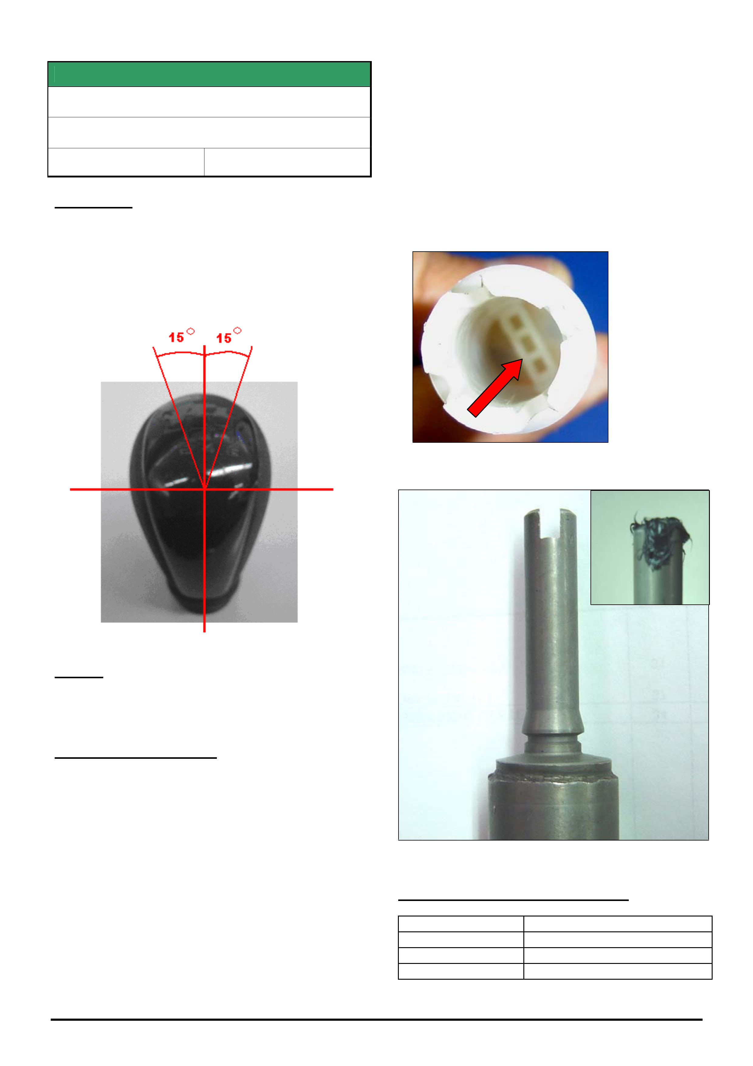
HOLDEN SERVICE TECHLINE __________________________________________________________________________________JULY, 2005
11
Holden Techlines are written to inform technicians of conditions that may occur on some vehicles, and to provide information that could assist in the
proper service fix of a vehicle. If a condition is described, do not assume the service fix applies to a vehicle or that the vehicle will have that condition.
SERVICE FIX
Gear Knob Rotates
VZ with HFV6 Aisin 6 Speed M/T
Group 7A Ref. No. TL0949 - 0506
CONDITION
Customers may complain that the gear knob rotates up
to 15 degrees in either direction as shown in figure 1.
Some dealers are replacing the gear knob and boot
assembly (P/N 92209169) in an attempt to fix the
problem. In most cases a replacement gear knob will
not fix the rotation.
Figure 1.
CAUSE
Excessive clearance between the internal mating
surfaces of the gear knob and shifter rod.
CORRECTION – Service
Should a customer report rotational movement or
'loose fitting' of the gear knob perform the following
steps;
1. Remove the gear knob and boot assembly. Refer to
Holden PV SIP for procedure.
2. Apply sufficient urethane or silicon based adhesive*
to fill the slot in the top of the lever (see figure 3).
3. Refit gear knob and boot assembly. Ensure the
teeth at the end of the inner plastic core anchor over
the lip at the base of the lever to prevent the gear knob
from lifting off.
4. Allow enough time for the adhesive to cure.
Note: The customer should be advised not to apply
excessive force to the knob until full strength bonding
is achieved in about 24 hours.
* Adhesive Details
- Urethane adhesive p/n 92143609 can be
purchased from HSPO.
- Loctite “BlackMax 5900” and Dow Corning 735 may
be purchased from most bearing suppliers or
engineering products retail outlets.
Figure 2. Internal rib inside inner core of gear knob
Figure 3. Fill slot in top of lever with adhesive.
WARRANTY CLAIM INFORMATION
Description Gear shift lever knob – R & R
Labour Op. No. K101100
Time 0.3 hr
Failure Code N0027 Loose

HOLDEN SERVICE TECHLINE __________________________________________________________________________________JULY, 2005
12
Holden Techlines are written to inform technicians of conditions that may occur on some vehicles, and to provide information that could assist in the
proper service fix of a vehicle. If a condition is described, do not assume the service fix applies to a vehicle or that the vehicle will have that condition.
INFORMATION
Repairs - Console and Phone Storage
Compartments
VY, VZ, WK WL Series
Group 1 Ref. No. TL0942 - 0506
Many console and phone storage compartment
assemblies are being replaced under warranty when
they could have been repaired.
Dealer service technicians should be aware that
replacement components are available to rectify some
failures within the console and phone storage
compartments.
IMPORTANT: Warranty claims may not be accepted
when compartment assemblies are replaced instead of
repairing.
The following repair procedures have been published
in Techlines.
1. Front and Rear Console Storage Compartment –
Door Latch Replacement – Nov 04, Issue 10 –
Page 9.
This techline should be completed when the lever arm
is broken or when the compartment will not close
due to insufficient interference in the lever pivot. If
the lever arm falls under its own weight, when the lever
pivot is fitted to the compartment, only the lever arm
should be replaced.
2. Phone Storage Compartment Lid Won’t Open –
Dec 04, Issue 11 – Page 13.
The new link arm should be fitted to both sides of the
phone storage compartment when required to rectify
the reported concern.
INFORMATION
Using The Internet To Obtain Warranty
Exchange Axle Units From Dana
V & W
Group 4 Ref. No. TL0640A - 0506
This Techline supersedes the previous one in Issue 2,
March, 2004. It is re-issued to highlight the
requirement to use Internet communications with
DANA and NOT fax.
Warranty axle exchange requests are to be provided to
Dana via their internet website rather than by the
previously used fax method. The fax method is still
being employed by many Dealer Service departments.
Using the fax method results in slower processing and
supply of exchange axle assemblies because of the
necessary multiple handling of fax sheets, transferring
to a computerised database, plus the necessity to reply
by fax (not always reliable).
Using the website allows Dealer personnel to track
their current Dealer requests plus a log of the “previous
50” requests.
Dana Automotive Systems Group is Holdens supplier
of V & W car rear and front drive axle units for vehicle
production, and contact details are as follows:
Dana Website
Dana should be contacted on their Website for all
warranty axle exchange requests and LSD “chatter”
kits.
Information on the use of the Dana Website have been
published in Dealer Letters DL 54/01 & RL 83/02.
Dana Website address is:
http://www.spiceraxle.com.au
Axle Warranty Enquiries
For any issues relating to supply of exchange axle
units not addressed by the Website – contact:
Robert Linton : (02) 9892 9237, Fax: (02) 9892 9310
Michael Morgan: (02) 9892 9343, Fax: (02) 9892 9442
Address Details
Dana Automotive Systems Group
205 - 231 Fairfield Road (Cnr. Foray Street)
Yennora, NSW 2161
These details and advice on access to exchange axle
assemblies via the Dana website are shown in
Passenger SIP.
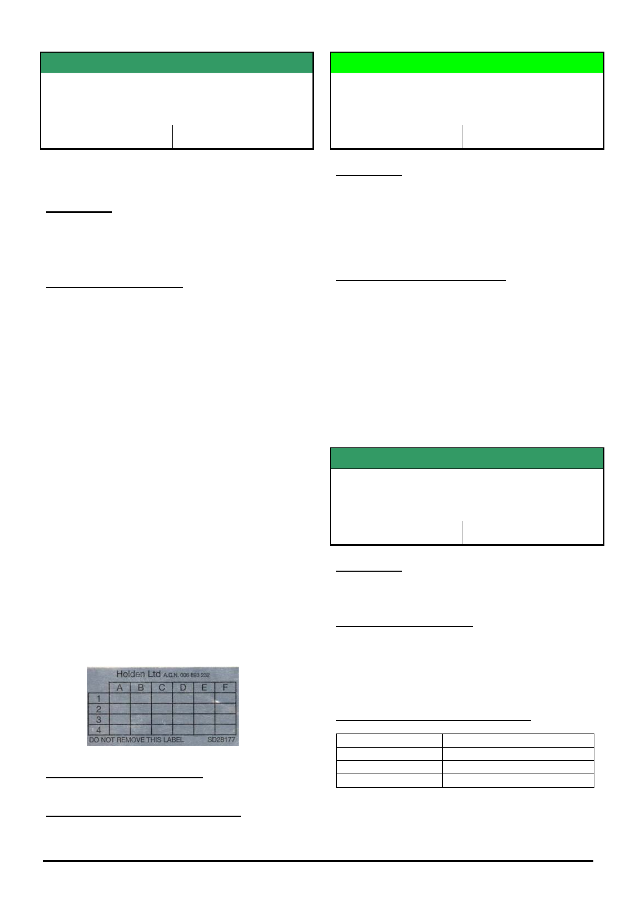
HOLDEN SERVICE TECHLINE __________________________________________________________________________________JULY, 2005
13
Holden Techlines are written to inform technicians of conditions that may occur on some vehicles, and to provide information that could assist in the
proper service fix of a vehicle. If a condition is described, do not assume the service fix applies to a vehicle or that the vehicle will have that condition.
SERVICE FIX
A/T Shift Pattern / Sports Mode Concerns
AH Astra
Group 7B Ref. No. TL0934A - 0506
This Techline supersedes the previous one, TL0934-
0505. It is revised by adding the note on selecting
“Country of Registration.” during SPS programming.
CONDITION
Some customers may complain of poor performance,
cabin booms in normal driving mode, and/or holding
gears until redline when in sports mode.
CORRECTION – Service
If a customer complains about the above described
conditions, reprogram the Transmission Electronic
Control Unit via the standard Service Programming
System (SPS) method using TIS 2000, CD 61 or later.
IMPORTANT: During SPS programming, the Country
Of Registration must be set to Australia. If this is left as
“Other” an error message will advise that the vehicle
currently has the latest calibration.
The latest transmission calibration installed off TIS
2000 CD 61 (or later) has the following revisions:
'Normal' driving mode - Revision in shift points and
lock up points for torque converter (occurring slightly
later in RPM range compared to current production
calibration). This improves performance feel, where
engine won't labour, and also reduces cabin booms.
'Sports' driving mode - Revision in shift points, where
auto transmission won't hold in gears until redline.
Improved Calibration Details:
Opel Part No. 55560969 Software Version No. 1010.
To identifiy vehicles that have had the above
procedure performed, apply a service history label on
the the inner left side of the glovebox door and mark
the coordinate “A-2” with a ball point pen to indent the
foil sticker. Refer following figure.
CORRECTION – Production
Breakpoint details will be published when this occurs.
WARRANTY CLAIM INFORMATION
Use Labour Times information in Warranty Information
section of current PV SIP CD
DIAGNOSIS HINT
Squeak From Steering Gear Input Shaft
VY, VZ, WK & WL
Group 9 Ref. No. TL0945- 0506
CONDITION
Squeak appearing to come from the region of the input
shaft of the steering gear.
One possible cause for this squeak has been identified
as insufficient lubrication of the dust boot.
SERVICE RECOMMENDATION
When attempting to diagnose/rectify the above
complaint, it is recommended to lubricate around the
top lip of the dust boot with a product such as Dow
Corning 200 fluid 30000 CST, or other equivalent
silicone based lubricant.
SERVICE FIX
Soft Tonneau Cover Pull Tabs Break
VY, VZ Utility and Crewman
Group 1 Ref. No. TL0916 - 0506
CONDITION
The tonneau cover pull tabs break in service.
CORRECTION – Service
The tonneau cover should be repaired by replacing the
pull tabs. This will require subletting to an auto
trimmer. The repair instructions are shown on the next
page.
WARRANTY CLAIM INFORMATION
Description R & R soft tonneau cover
Labour Op. No. R407200
Time 0.3 hr
Failure Code R0001 Broken
The sublet cost is to be entered in the relevant area of
the warranty claim. Use Sublet Type EX (external trim)
x
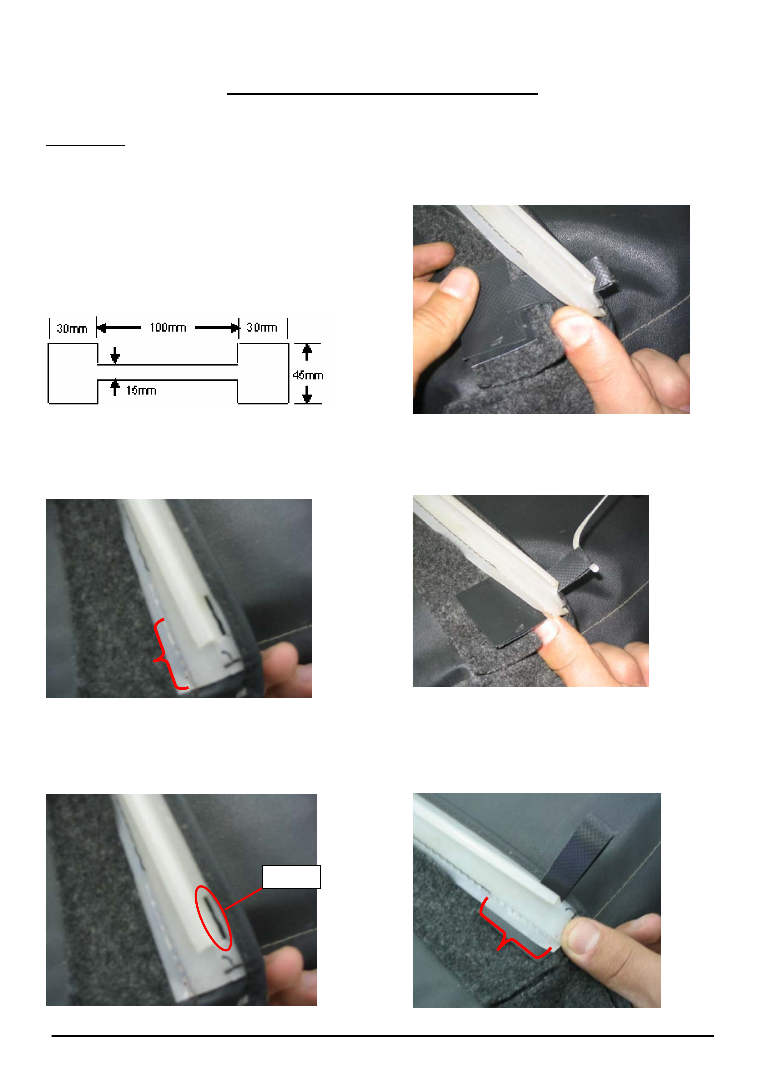
HOLDEN SERVICE TECHLINE __________________________________________________________________________________JULY, 2005
14
Holden Techlines are written to inform technicians of conditions that may occur on some vehicles, and to provide information that could assist in the
proper service fix of a vehicle. If a condition is described, do not assume the service fix applies to a vehicle or that the vehicle will have that condition.
Soft Tonneau Cover Tab Repair Procedure
Tab Material.
The recommended tab material is “Tarpol TS” which can
be purchased from RADINS phone (03) 9587 5600. This
material is a heavy duty, PVC coated, tear stop fabric
from a woven, high tenacity polyester cloth. When
ordered the material must be black in colour and the mat
surface finish exposed.
Step 1
Cut recommended material to dimensions specified
below.
Step 4
Fold and insert new pull tab under plastic extrusion
and through slot. Ensure mat surface finish is
exposed.
Step 2
Carefully unstitch the thread away from the plastic
extrusion (approx 50mm).
Step 5.
Pull tab through slot.
Step 3
Fold and insert new pull tab under plastic extrusion and
through slot. Ensure mat surface finish is exposed.
Step 6
Re stitch Pull Tab through existing thread holes of
plastic extrusion in order to maintain strength.
Slot
HOLDEN SERVICE TECHLINE __________________________________________________________________________________JULY, 2005
15
Holden Techlines are written to inform technicians of conditions that may occur on some vehicles, and to provide information that could assist in the
proper service fix of a vehicle. If a condition is described, do not assume the service fix applies to a vehicle or that the vehicle will have that condition.
SERVICE FI
X
EGR Malfunction, DTC P0400 Sets
XC Combo (Z16SE Engine) Model Years 2003
& 2004 Only
Group 6C Ref. No. TL0941- 0506
CONDITION
Drivers may complain of engine running ‘rough’ and/or
may stall at times during this ‘rough running’ period,
and engine check lamp illuminates.
Technicians may find a DTC P0400 set.
CAUSE
Deposits of contaminants built up between the EGR
pintle and its guide causing the pintle to seize.
CORRECTION – Service
Summary: On complaint vehicles ensure EGR valve is
fully closed before disabling its operation with revised
engine management software.
If diagnosis of driveability complaints leads to an EGR
malfunction and DTC P0400 is logged, perform the
following steps:
Step 1. Check position of the EGR Valve.
The position of the EGR valve can be found by
performing the 'Actuator test' with TECH 2, selected as
follows:
Diagnostics,
Model Year,
Vehicle Type,
Engine,
Actuator test,
EGR Solenoid test,
EGR position Feedback.
(1a). If the EGR position feedback is between 0.15V
and 1.5V after performing the test (Test Status:
Inactive) the EGR valve is closed - Go to Step 2.
(1b). If the EGR position feedback is higher than
1.5V after performing the actuator test (Test Status:
Inactive) the EGR valve is not completely closed and
should be replaced with a new one from HSPO.
Perform the actuator test again when the new
valve is installed to ensure the valve closes fully.
Once confirmed, proceed to step 2.
Step 2. Reprogram ECU.
Reprogram the ECU with modified software,
available from TIS CD 61 and onward, to deactivate
the EGR function.
Note: two ECU hardware numbers exist for the
vehicle - the correct hardware number and revised
ECU software part numbers are listed below.
ECU Hardware
Number
Service ECU
Part No.
EGR Disable
ECU Software
Part No.
DEL 0115351289 9391340 12 214 840.7
DEL 0115214590 12214810 12 237 460.6
Step 3. Vehicle Marking
All vehicles that are modified according to the above
information are required to be clearly marked by a
yellow paint dot on the upper side of the EGR valve
housing. This will alert service technicians that the
engine management system has been revised and
the EGR is disabled.
WARRANTY CLAIM INFORMATION
Use Labour Times information in Warranty Information
section of current PV SIP CD
Update

HOLDEN SERVICE TECHLINE __________________________________________________________________________________JULY, 2005
16
Holden Techlines are written to inform technicians of conditions that may occur on some vehicles, and to provide information that could assist in the
proper service fix of a vehicle. If a condition is described, do not assume the service fix applies to a vehicle or that the vehicle will have that condition.
INFORMATION
Explanation of Driveline “Clunk” or “Backlash
Noise”
All Rear Drive Vehicles
Group 4 Ref. No. TL0956 - 0506
Some owners of rear wheel drive vehicles may
comment that the vehicle exhibits a “clunk” noise while
driving when the accelerator is depressed and then
released.
Similarly, owners of vehicles equipped with either
manual or auto transmissions may comment that the
vehicle exhibits a “clunk” noise when shifting between
Park & Drive, Park & Reverse or Drive & Reverse.
Whenever two or more gears interact with one another,
there must be a certain amount of clearance between
those gears in order for the gears to operate properly.
This clearance or freeplay (backlash) can translate into
a clunk noise whenever the gear is loaded and
unloaded quickly, or whenever the direction of rotation
is reversed.
The more gears/components you have in a system, the
more freeplay the total system will have.
The clunk noise that owners sometimes hear may be
the result of a stackup of freeplay (backlash) between
the components in the driveline.
For example: The potential for a driveline clunk would
be greater in a 4WD or AWD vehicle than in a 2WD
vehicle.
This is because in addition to the freeplay from the rear
axle gears, the drive shaft joints, and the transmission
(common to all vehicle types), the 4WD transfer case
and front drive shaft/s (and their associated
clearances) add additional freeplay to the driveline.
In service, dealers are discouraged from attempting to
repair driveline clunk conditions for the following
reasons:
• Driveline clunk is almost never the result of one
individual component with excessive freeplay, but
rather the result of the cumulative effect of
freeplay (backlash/lash) that is present in all of the
driveline components.
Because all of the components in the driveline
have a certain amount of freeplay (backlash) by
design, changing driveline components may not
result in a satisfactory freeplay (or driveline clunk)
reduction.
• While some owners may find the clunk noise
objectionable, this will not adversely affect the
durability or performance of the vehicle or its
components.
HOLDEN SERVICE TECHLINE _______________________________________________________________________________AUGUST, 2005
5
Holden Techlines are written to inform technicians of conditions that may occur on some vehicles, and to provide information that could assist in the
proper service fix of a vehicle. If a condition is described, do not assume the service fix applies to a vehicle or that the vehicle will have that condition.
SERVICE FIX
Check Engine Light Illuminates and the PCM
Sets DTC P1626 until key is cycled
VY AWD
Group 12 Ref. No. TL0927- 0507
CONDITION
Customers may advise that intermittently the check
engine light illuminates and when the ignition is cycled
it goes out.
When DTC’s are checked with Tech 2, a history DTC
P1626 may be found in the PCM.
CAUSE
A weakness in PIM software caused intermittent loss
of communication between the PIM and the PCM.
CORRECTION – Service
After verifying that vehicle has the condition described
above, fit the revised PIM following the standard SIP
procedure.
PARTS INFORMATION
Part No.: Partfinder Name Qty:
92184712 Powertrain Interface Module
(PIM)
1
WARRANTY CLAIM INFORMATION
Use Labour Times information in Warranty Information
section of current PV SIP CD
DIAGNOSIS HINT
Headlamps Intermittently Don’t Switch Off
Automatically After Leaving The Vehicle
VY, V2II & III, VZ, WK, WL
Group 12 Ref. No. TL0969-0507
Customers may report that occasionally the headlights
don’t switch off automatically after they leave the
vehicle.
When investigating this complaint, dealers need to
ensure the door light switch in the drivers side A pillar
is correctly grounding to the body through the screw
and switch base and the BCM is receiving the door
light switch input.
If no obvious fault can be found, the customer needs to
be questioned about when the problem occurs.
If the customer is switching the ignition key off prior to
the vehicle being stationary, the headlights will not
turn off automatically (i.e. coasting to a stop or rapid
parking, key off combination).
Customers need to be made aware this feature is
designed into the vehicle for their safety to ensure the
headlights don’t turn off while they are driving in the
event of a fault within the vehicle.

HOLDEN SERVICE TECHLINE _______________________________________________________________________________AUGUST, 2005
7
Holden Techlines are written to inform technicians of conditions that may occur on some vehicles, and to provide information that could assist in the
proper service fix of a vehicle. If a condition is described, do not assume the service fix applies to a vehicle or that the vehicle will have that condition.
INFORMATION
TIS 2000 Fails Update/Installation Procedure
All
Group: OB Ref. No.: TL0964 - 0507
The purpose of this Techline is to advise Dealers of
possible causes for TIS 2000 failing to update or install
due to the CD data not being read by the CD Drive.
Upon investigations carried out at Holden Dealerships
it has been found that the main causes for this are:
Faulty or Dirty CD-ROM.
For cases where a dirty CD is thought to be the
problem, cleaning the CD will usually correct the error.
CD-ROM cleaning kits are available through retail
outlets such as office suppliers and computer stores.
In cases where the CD shows visible sign of damage
or, after cleaning it still fails to update or install, a
replacement CD will be required.
Note: If a replacement TIS 2000 CD is required,
contact Andrew Janson on (03) 9647 7632 at Holden
Aftersales Service.
Faulty or dirty hardware (CD Drive).
For cases where faulty or dirty hardware is thought to
be the problem, trying the CD in another CD drive is a
good way of confirming if the original CD drive is at
fault. If the suspect CD is placed in another drive and
works successfully, this is a clear indication that the
original CD drive is faulty or dirty.
Note: Typical Service Department environments are
very harsh on computers. With this in mind, when
faulty or dirty hardware is thought to be the cause, it
would be advisable to use a computer that is kept in a
less harsh environment (less dust), or use a computer
that has had a new CD Drive recently installed.
If the CD Drive is found to be faulty, it is strongly
recommended that a CD/DVD reader be purchased as
a replacement, as TIS 2000 will be delivered only on
DVD media from the beginning of 2006. For more
information regarding TIS 2000 on DVD, refer to All
Dealer Letter 25/05.
HOLDEN SERVICE TECHLINE _______________________________________________________________________________AUGUST, 2005
9
Holden Techlines are written to inform technicians of conditions that may occur on some vehicles, and to provide information that could assist in the
proper service fix of a vehicle. If a condition is described, do not assume the service fix applies to a vehicle or that the vehicle will have that condition.
INFORMATION
TAS Vehicle Call Groups
Group OB Ref. No. TL0963 - 0507
TAS receive many calls where the caller has selected the incorrect group on the phone system for the vehicle model
they are enquiring about. Please refer to the following dialling options (numbers) when navigating through the TAS
phone system.
Introductory Message
HOLDEN dial 1 SAAB dial 2
Bulletin Board
- dial 1
LCV & Daewoo vehicles
- dial 2
• Jackaroo
• Frontera
• Cruze
• Rodeo
• ALL DAEWOO
badged vehicles.
Holden Passenger vehicles
- dial 3
• Commodore / sedan /
wagon / ute / 1 tonner /
crewman / AWD
• Statesman, Caprice
• Monaro
• Zafira
• Astra
• Vectra
• Barina
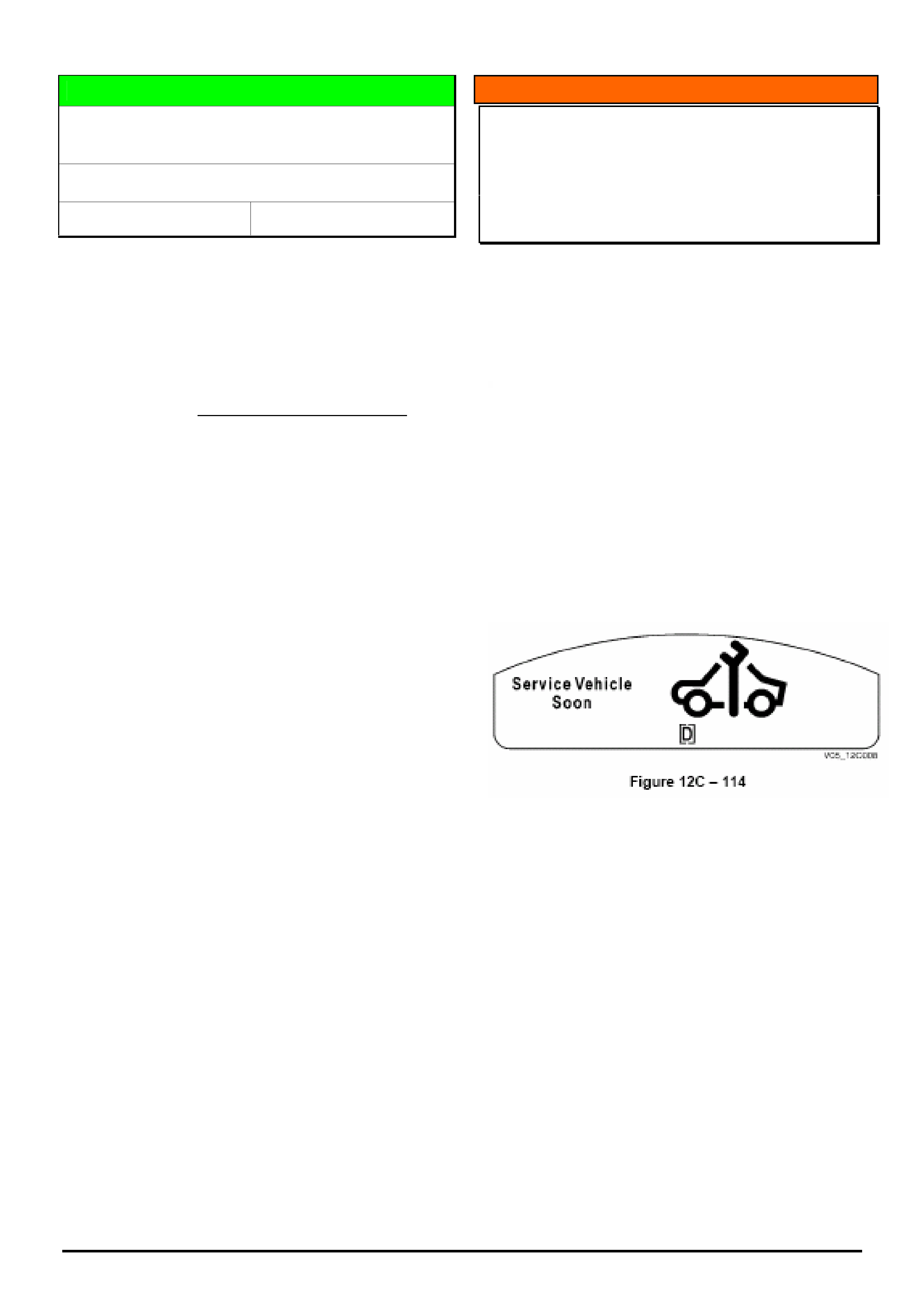
HOLDEN SERVICE TECHLINE _______________________________________________________________________________AUGUST, 2005
10
Holden Techlines are written to inform technicians of conditions that may occur on some vehicles, and to provide information that could assist in the
proper service fix of a vehicle. If a condition is described, do not assume the service fix applies to a vehicle or that the vehicle will have that condition.
DIAGNOSIS HINT
Euro 3 Exhaust System Fitted to VZ AWD
175kw Engine
VZ AWD Models with Alloytec 175 Kw engine
Group 6C Ref. No. TL0959-0507
From the start of production of the above models, the
HFV6 175 kw engines have been upgraded to Euro 3
fuel and exhaust system which means they now have
four O2 sensors. i.e. 2 before and 2 after the catalytic
converter.
This now makes engine fault diagnosis the same as for
the 190 kw engine for O2 sensor diagnostics only.
INFORMATION
“Service Vehicle Soon” Displayed In
Instrument Cluster
VZ and WL
(GROUP OB) TL0972-0507
TAS has received several calls where Dealers advise
that the instrument cluster displays “Service Vehicle
Soon”. It appears that some Dealers believe it to be a
service reminder or are unsure what it means and
therefore call TAS.
“Service Vehicle Soon” does not mean that the vehicle
is due for its scheduled service, but rather that the
engine ECU has logged a Diagnostic Trouble Code
(DTC).
If this is displayed check for DTC’s and follow the
normal diagnostic procedure laid out in SIP.
The following is taken from SIP relating to the service
vehicle soon message. Please ensure that all such
information is checked prior to calling TAS.
Service Vehicle Soon – Non Emissions Related Fault
The Service Vehicle Soon message is displayed if the ECM
or the PCM (for V8) has detected an engine fault. It appears
as a large warning symbol.
A chime sounds with this warning.
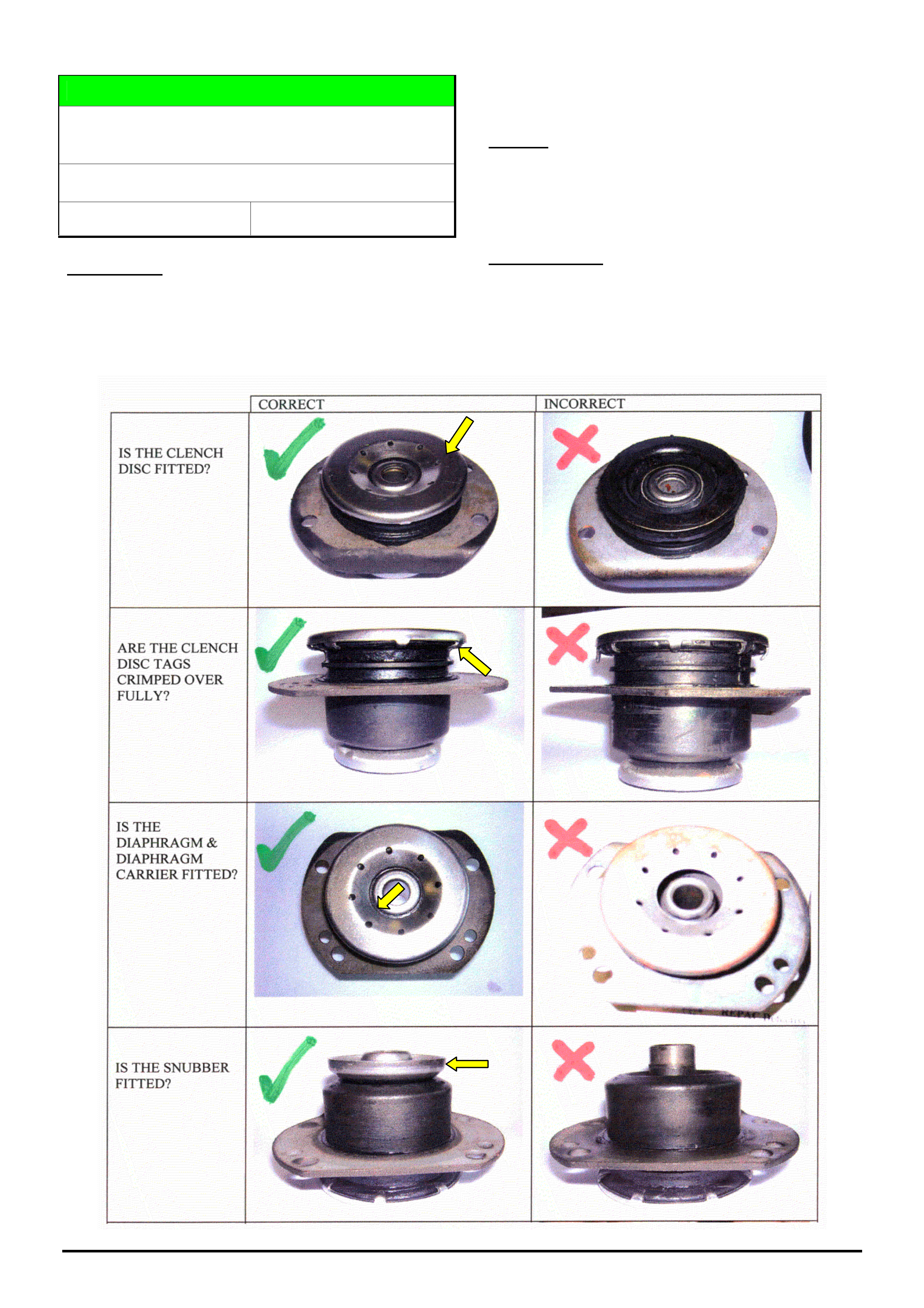
HOLDEN SERVICE TECHLINE _______________________________________________________________________________AUGUST, 2005
11
Holden Techlines are written to inform technicians of conditions that may occur on some vehicles, and to provide information that could assist in the
proper service fix of a vehicle. If a condition is described, do not assume the service fix applies to a vehicle or that the vehicle will have that condition.
DIAGNOSIS HINT
Front Control Arm Rod Hydraulic Bush Fault
Diagnosis.
VZ, WL
Group 3 Ref. No. TL0965- 0507
CONDITION
Vehicle has one or more of the following symptoms.
1. Front end knocking under brakes.
2. Vehicle veering.
3. Abnormal tyre wear.
CAUSE
A possible cause for the above conditions is the front
control arm rod hydraulic bush is incorrectly
assembled or has components missing.
CORRECTION
Check bush for any of the conditions shown in
diagrams below. Replace any faulty bushes.
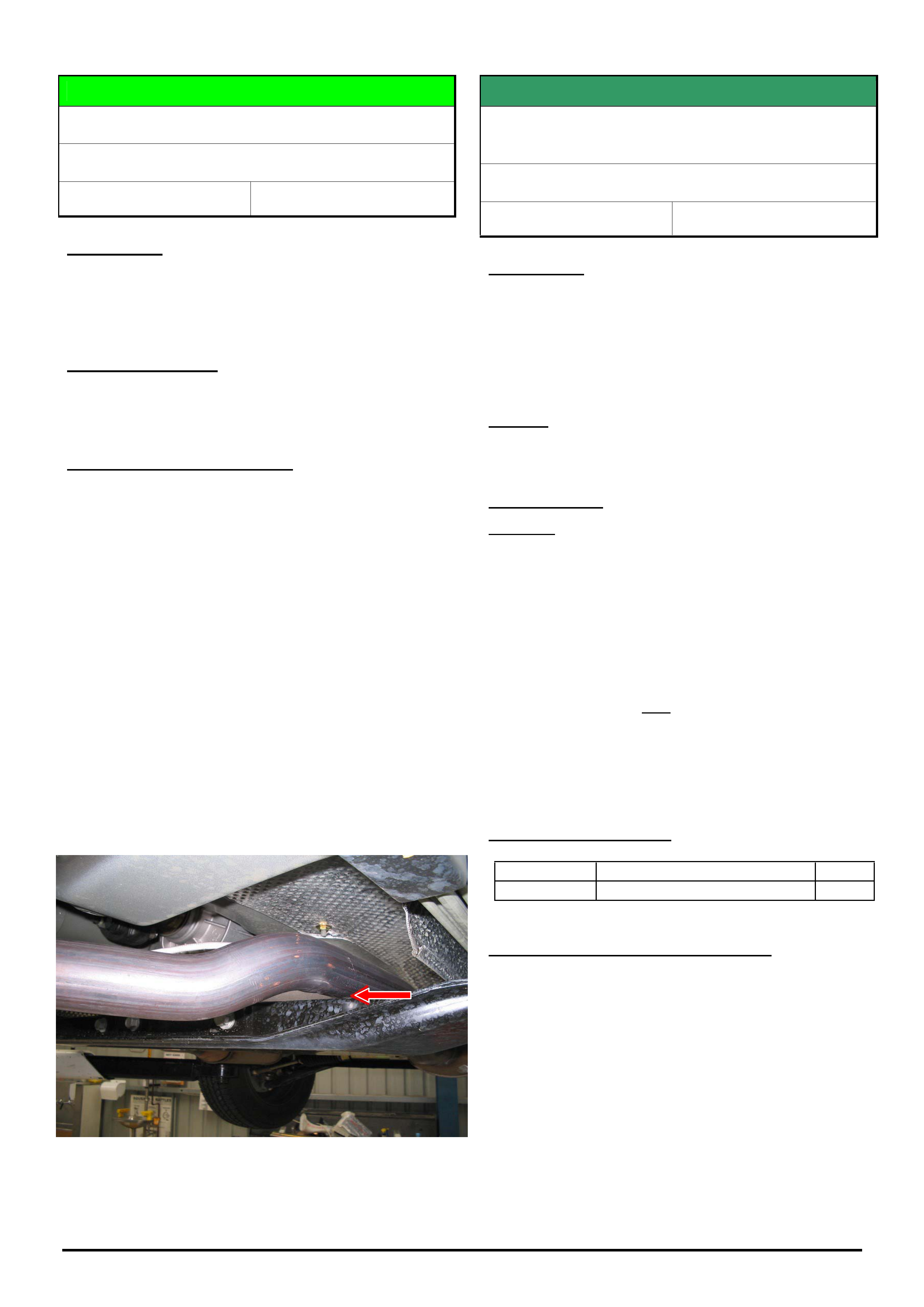
HOLDEN SERVICE TECHLINE _______________________________________________________________________________AUGUST, 2005
12
Holden Techlines are written to inform technicians of conditions that may occur on some vehicles, and to provide information that could assist in the
proper service fix of a vehicle. If a condition is described, do not assume the service fix applies to a vehicle or that the vehicle will have that condition.
DIAGNOSIS HINT
Knock From Underneath Vehicle
VZ AWD HFV6 Cab Chassis
Group 8 Ref. No. TL0939 - 0507
CONDITION
Audible knock from underneath vehicle usually on
rough road surfaces or on flat road under high engine
torque.
POSSIBLE CAUSE
Exhaust pipe contacting transmission cross member
due to insufficient clearance.
SUGGESTED CORRECTION
On any vehicle where the exhaust pipe is suspected of
contacting the transmission cross member, try the
following procedure.
1. Loosen the front exhaust pipe to manifold flange
joints and the four exhaust transmission brace
bolts.
2. Place a 20mm chock between the right hand pipe
and transmission cross member. Refer figure 1.
3. Torque up the four front pipe to manifold flange
joints and exhaust brace bolts. Refer PV SIP
instructions.
4. Remove the chock used in step 2.
5. The result should be a 15mm clearance between
both LH and RH exhaust front pipes to cross
member.
Figure 1. Place 20mm chock at location of red arrow
SERVICE FIX
“Soft” Clutch Pedal or Cruise Control
“Drop-out”
ZC, 4 Cyl, M/T
Group 7A Ref. No. TL0960- 0507
CONDITION
Cruise control may intermittently NOT set
or
intermittently ‘drop out’,
or
the clutch pedal may feel ‘soft’.
CAUSE
Clutch pedal return spring broken.
CORRECTION
Summary: Replace clutch pedal return spring, NOT
the pedal box assembly.
Note: Previously this breakage necessitated replacing
the whole pedal box - but a clutch pedal return spring
has now been made available to reduce the
complexity/cost of repairs and minimise the
disturbance to the vehicle.
When a clutch pedal return spring breakage is
confirmed - replace only the broken spring as per
service procedures in TIS under clutch pedal
replacement.
Do not replace the pedal (box) assembly.
PARTS INFORMATION
Part No.: Partfinder Name Qty:
93183937 Spring - Clutch Pedal 1
WARRANTY CLAIM INFORMATION
Use Labour Times information in Warranty Information
section of current PV SIP CD (SUP Section).
HOLDEN SERVICE TECHLINE _______________________________________________________________________________AUGUST, 2005
13
Holden Techlines are written to inform technicians of conditions that may occur on some vehicles, and to provide information that could assist in the
proper service fix of a vehicle. If a condition is described, do not assume the service fix applies to a vehicle or that the vehicle will have that condition.
SERVICE FIX
Rear Axle “Cyclic Knock” .
All V & W with IRS (non LSD)
Group 4 Ref. No. TL0602B- 0507
This Techline supercedes the previous one in Issue 2,
Feb., 2005. It is revised by removing breakpoint
information and upgrading the correction procedure.
CONDITION
Cyclic knock noise may occur when coasting or on
light throttle in speed range between 40-70km/hr while
driving in a straight line.
This condition is confirmed if the cyclic knock noise
disappears when the vehicle is driven in a ‘slalom’
motion.
CAUSE
Excessive axial float (circlip) and clearance of the inner
axle shaft (splines) within the differential.
Condition affects V & W models with IRS (non LSD).
CORRECTION
After verifying that vehicle has symptoms as described
above, proceed as follows: THIS PROCEDURE WILL
REQUIRE THE VEHICLE TO BE IMMOBILISED
AFTER THE REPAIR FOR AT LEAST SIX HOURS.
Procedure.
1. Contact Dana via their website to register a case
of “cyclic knock”.
Once case is approved, Dana will send a set of
differential inner-axle assemblies with “upper
spec. spline” and reduced clearance circlip
grooves for the complaint vehicle.
2. Remove LHS and RHS driveshafts.
NOTE: mark the inner CV joints of both driveshafts
before completely removing from the vehicle.
(Refer SIP Section 4B, 2.7 "Driveshaft Assembly”)
3. Remove LHS and RHS inner-axles from
differential.
(Refer SIP Section 4B, 2.9 "Inner Axle Shaft Seal".
Note: Diff does not need to be removed from
vehicle.)
4. If the shafts supplied by Dana do not come with
circlips installed, then Install new circlips p/n
92140242.
5. Clean all traces of oil from splines of the new
shafts and from the matching splines in the
differential. Follow the pre-application cleaning
instructions provided on the Loctite 609 package.
6. Apply Loctite 609 to the splines on the shafts
before assembling the new shafts into the
differential.
7. NOTE: Do NOT start the engine, move the
differential shafts, or install the driveshafts
- Allow Loctite to cure for 6 hours minimum
before proceeding.
8. At the end of the six hour minimum
immobilisation time - Reverse both driveshafts
before reinstalling. (This means: reinstalling
driveshafts with the original inner CV joint now on
the outer end).
PARTS INFORMATION
Part No.: Partfinder Name Qty:
92140242 Ring - Rear Axle Shaft
Retainer (circlip)
2
WARRANTY CLAIM INFORMATION
For vehicles covered under warranty use the following
information.
Description Diff Cyclic Knock Noise
Reduction Procedure
Labour Op. No. F000200
Time 1.8 hr
Failure Code F0040 noisy
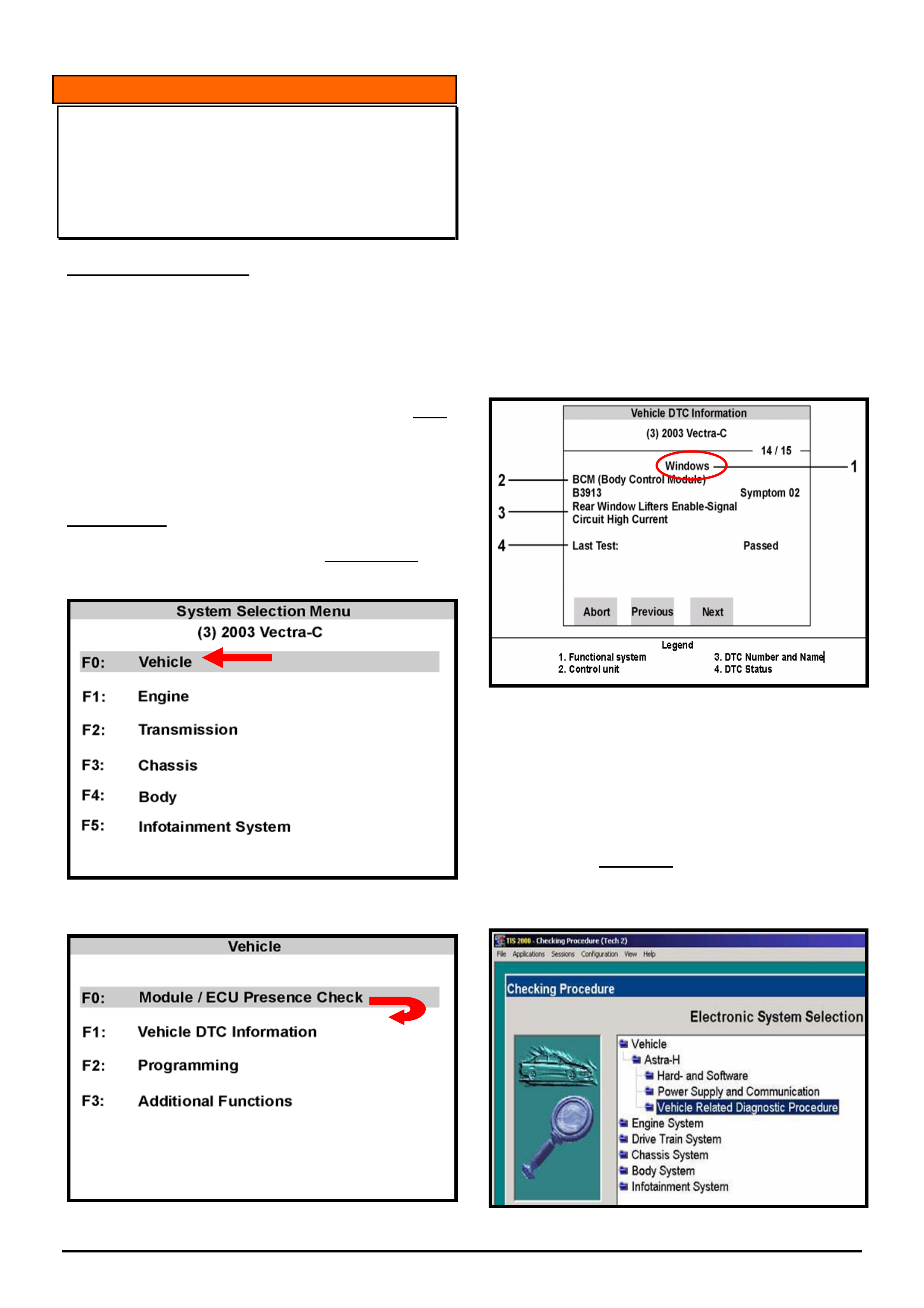
HOLDEN SERVICE TECHLINE _______________________________________________________________________________AUGUST, 2005
14
Holden Techlines are written to inform technicians of conditions that may occur on some vehicles, and to provide information that could assist in the
proper service fix of a vehicle. If a condition is described, do not assume the service fix applies to a vehicle or that the vehicle will have that condition.
INFORMATION
TIS 2000 Vehicle Related Diagnostic
Procedure (Finding DTC’s & Code Index’)
MODEL: ZC Vectra & AH Astra
(GROUP OB) TL0973-0507
SERVICE INFORMATION
Due to the introduction of the multiple CAN-BUS
system now used on ZC Vectra and AH Astra the use
of Tech 2 and TIS 2000 diagnostic procedure has
changed as result of this. Locating diagnostic trouble
codes (DTCs) and programming code indexes within
TIS 2000 has also changed because of this.
A new “Vehicle Related Diagnostic Procedure” must
now be followed.
For a more detailed explanation of the entire new
diagnostic procedure refer to Technicians Guild No.6
2003.(Highly recommended)
PROCEDURE
When using Tech2 on AH and ZC, before checking for
DTC’s an ECU presence check must always be
performed first. Refer figures 1 & 2
Figure 1
Figure 2
After successfully completing an ECU presence check,
the next step is checking for DTC’s; select F1 “Vehicle
DTC Information. Refer figure 2.
Any diagnostic trouble codes stored now belong to
“functional groups”, and the additional information
displayed on Tech 2 along with the DTC number is
vital for locating the relevant procedure in TIS 2000.
Refer figure 3 for an example of a stored DTC.
This DTC B3913 is rear window lifter enable circuit
high current, although it is reported by the Body
Control Module (BCM), the DTC belongs to the
functional group known as “Windows”, and it is this
functional group that must be referred to in TIS.
Tech 2 Display
Figure 3
To locate this DTC in TIS 2000 select “Vehicle” then
“Vehicle Related Diagnostic Procedure” from the
Electronic System Selection menu in Checking
Procedures. Refer figure 4. Selecting systems such as
Engine, Drive Train, Chassis or Body as previously
done on earlier Opel vehicles to obtain the DTC
procedure can no longer be performed this way for
AH and ZC.
Figure 4
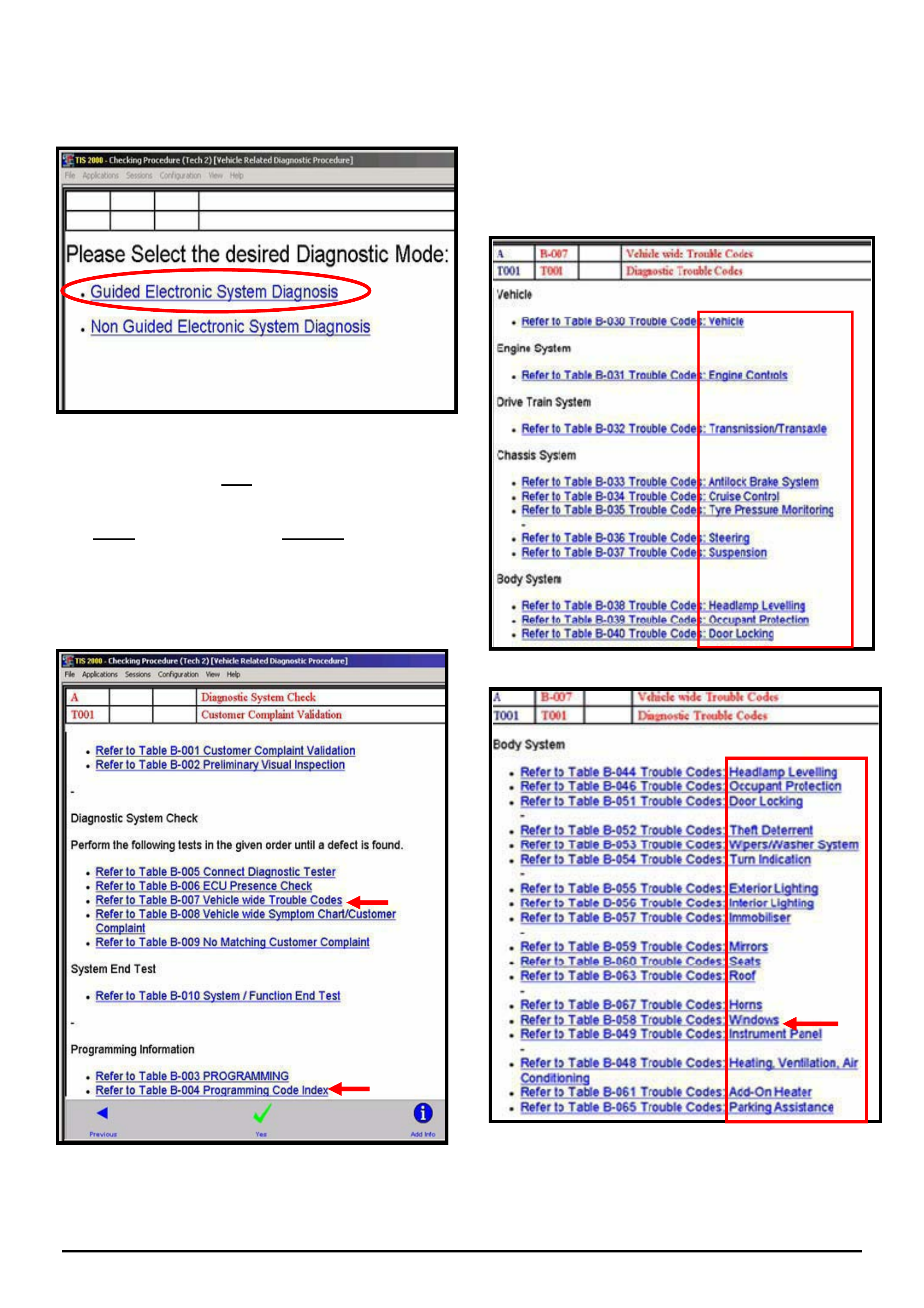
HOLDEN SERVICE TECHLINE _______________________________________________________________________________AUGUST, 2005
15
Holden Techlines are written to inform technicians of conditions that may occur on some vehicles, and to provide information that could assist in the
proper service fix of a vehicle. If a condition is described, do not assume the service fix applies to a vehicle or that the vehicle will have that condition.
Next, select the desired diagnostic mode:
“Guided Electronic System Diagnosis” refer figure 5.
Figure 5
Displayed next is the new Diagnostic System Check
menu. Refer figure 6
This entire diagnostic process must be followed from
start to finish, starting with preliminary measures, then
the diagnostic system check, finishing with the system
end test.
New Diagnostic System Menu
Figure 6
To locate the DTC B3913 reported by the functional
group known as windows, select Table B-007 Vehicle
wide Trouble Codes, refer figure 6. Then find the
functional group of windows located with the list of
functional groups refer figures 7 & 8. Displayed here is
a list of all the groups, starting with Vehicle, Engine
Controls, Transmission/Transaxle, Anti lock Brakes
etc.
Figure 7
Figure 8
Functional Groups Continued
Functional Groups
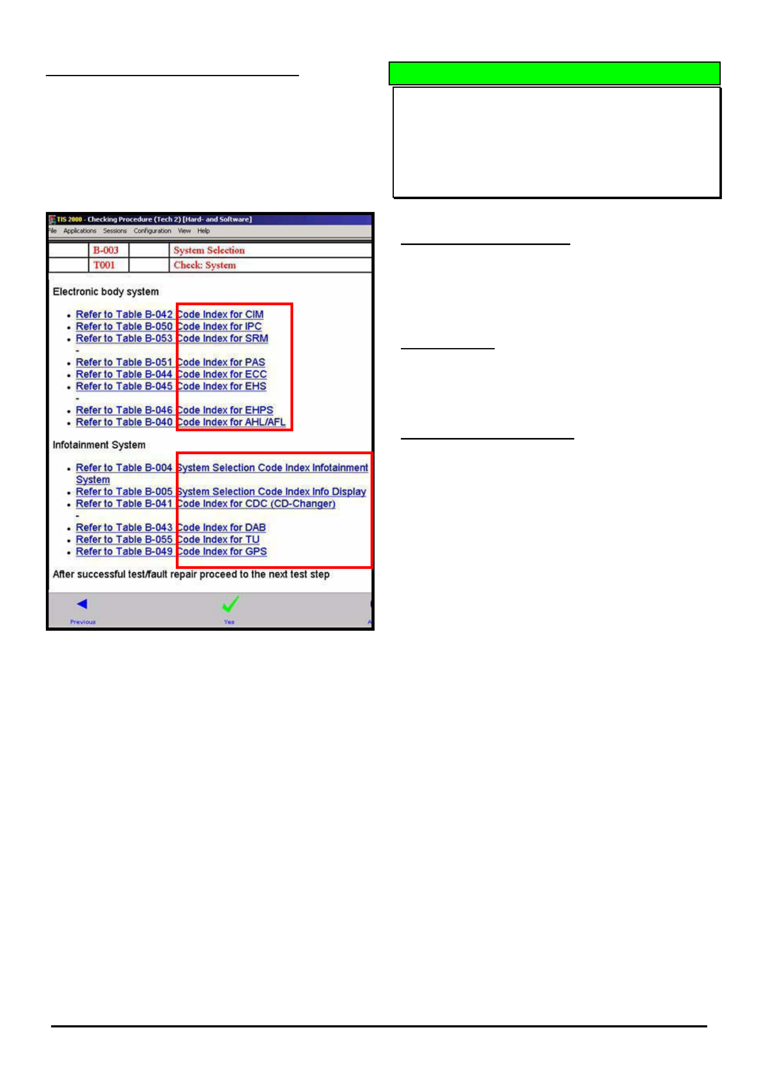
HOLDEN SERVICE TECHLINE _______________________________________________________________________________AUGUST, 2005
16
Holden Techlines are written to inform technicians of conditions that may occur on some vehicles, and to provide information that could assist in the
proper service fix of a vehicle. If a condition is described, do not assume the service fix applies to a vehicle or that the vehicle will have that condition.
LOCATING PROGRAMMING CODE INDEX
To locate Programming Code Indexes, from the same
diagnostic system check menu, refer figure 6, select
“Table B-004 Programming Code Index”,
Displayed next is a list of all the electronic modules and
the Tech 2 menu they belong to. Refer figure 9
Code Index Numbers
Figure 9
DIAGNOSIS HINT
No Tech 2 Communication with 4 cyl Z22SE
Engine ECU
TS Astra, Zafira
(GROUP OB) TL0974-0507
PROBLEM DESCRIPTION
Tech 2 will not communicate with 2.2 Litre Z22SE
engine ECU fitted to Astra and Zafira using Tech 2
software 14.200 from TIS 2000 Cd 62.
CORRECTION
Revised Tech 2 software to rectify this will be released
on TIS Cd 63 scheduled for release in August 2005.
SERVICE RECTIFICATION
To communicate with Z22SE engine ECU, install Tech
2 software version 14.103 by selecting the custom
download option in TIS 2000.
NOTE: once diagnosis is completed ensure Tech 2 is
reloaded with software 14.200 again.
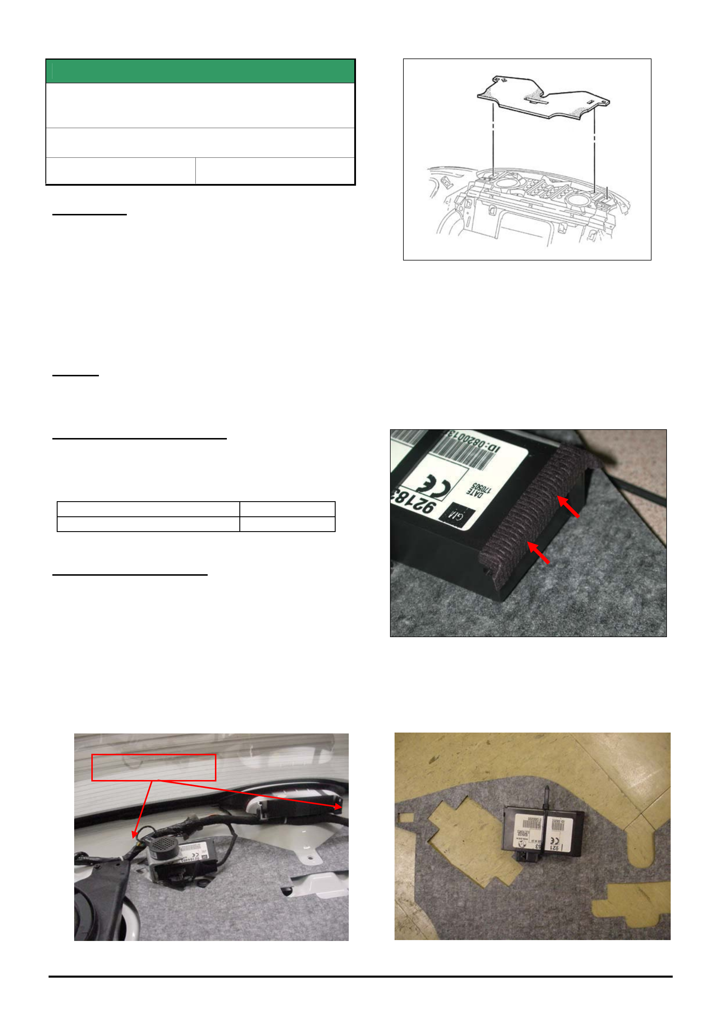
HOLDEN SERVICE TECHLINE _______________________________________________________________________________AUGUST, 2005
17
Holden Techlines are written to inform technicians of conditions that may occur on some vehicles, and to provide information that could assist in the
proper service fix of a vehicle. If a condition is described, do not assume the service fix applies to a vehicle or that the vehicle will have that condition.
SERVICE FIX
TPMS Module Unable To Detect One Or Both
Front Tyre Pressures & Sets DTC 9 or 10
WL Caprice, HSV Grange
Group 12 Ref. No. TL0970- 0507
CONDITION
Customers may advise they intermittently receive
warnings in their instrument cluster MFD (multi function
display) reporting no pressure reading from one or
both front tyres.
DTC 9 Front Left Pressure Sensor Circuit Range /
Performance and DTC 10 Front Right Pressure Sensor
Circuit Range / Performance may also set in the TPMS
module.
CAUSE
Reception limitation due to the location of the TPMS
module.
CORRECTION – Production
Vehicles in production have had the TPMS module
moved to a location which has better reception from
the following breakpoint.
ISOVIN: Built Date:
**********L473538 12/07/05
CORRECTION – Service
1. Remove the Rear Window Trim Panel Assembly
following the instructions in PV SIP section 1A8
Headlining and Interior Trim / 2.11 Rear Window
Trim Panel Assembly .
2. Remove the TPMS module from its bracket,
remove the two white harness securing clips which
locate the rear window panel insulator and remove
the rear window panel insulator (refer figure 1 & 2).
Figure 1
Figure 2
3. Using figure 7 (diagram located at the end of this
article) as a reference measure and cut out the two
holes required to mount the TPMS module on the
rear window panel insulator.
Note: Module alignment is critical.
4. Attach flocking tape part number 92145740 (or
equivalent) to the end of the module as per figure 3.
Figure 3
5. Secure the TPMS module to the rear window panel
insulator using cable tie part number 92138082.
Trim the excess length from the cable tie once the
module is secure (as per the figure 4).
Figure 4
White Harness Clips
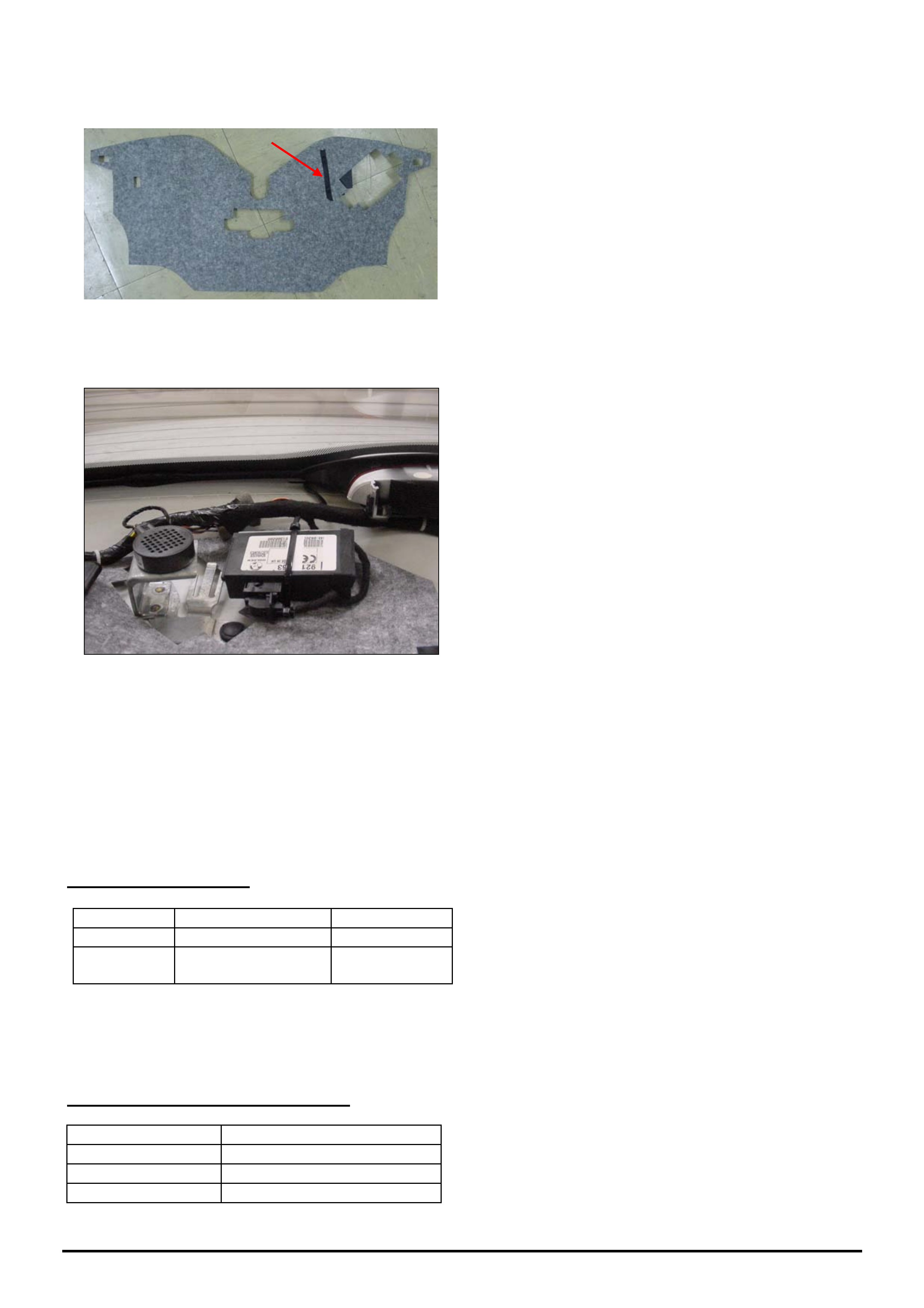
HOLDEN SERVICE TECHLINE _______________________________________________________________________________AUGUST, 2005
18
Holden Techlines are written to inform technicians of conditions that may occur on some vehicles, and to provide information that could assist in the
proper service fix of a vehicle. If a condition is described, do not assume the service fix applies to a vehicle or that the vehicle will have that condition.
6. Turn the insulator over and attach flocking tape (or
equivalent) to the exposed cable tie (as per figure 5).
Figure 5
7. Reinstall and reconnect the rear window panel
insulator and module (as per figure 6).
Figure 6
8. Reconnect & Reassemble the vehicle as per PV
SIP section 1A8 Headlining and Interior Trim / 2.11
Rear Window Trim Panel Assembly.
9. Road test to ensure the vehicle has no rattles and
squeaks, check the rear park assist functions and
that the tyre pressures are being displayed in the
MFD of the instrument cluster.
PARTS INFORMATION
Part No.: Partfinder Name Qty:
92138082 Cable Tie 1
92145740 Flocking tape 1 roll per
dealership*
* Note: The flocking tape part number is for an 11
metre roll of tape. Approx 200mm is required for each
vehicle.
WARRANTY CLAIM INFORMATION
Description Relocate TPMS module
Labour Op. No. N000487
Time 0.5 hr
Failure Code NOW N0057
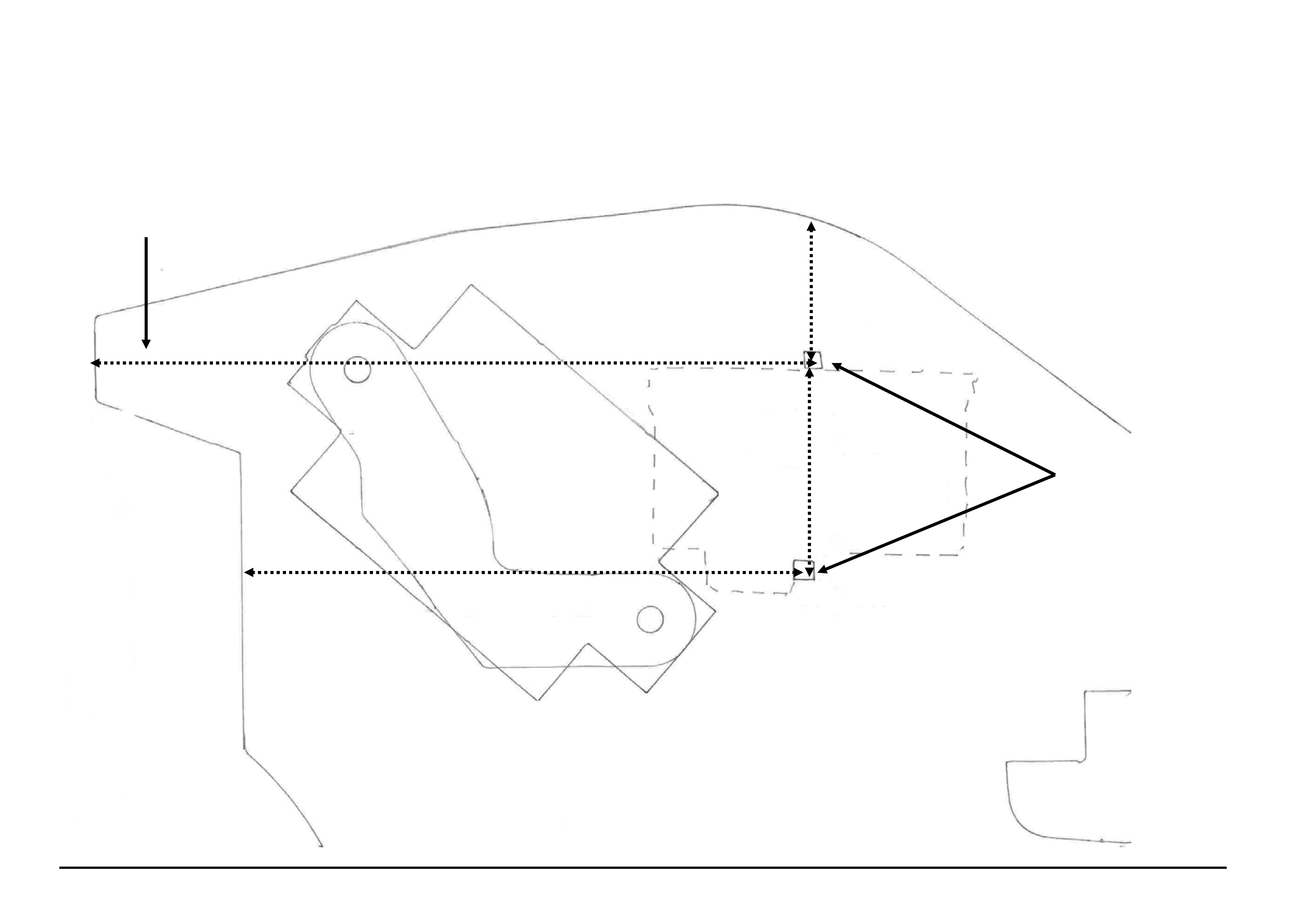
HOLDEN SERVICE TECHLINE _______________________________________________________________________________AUGUST, 2005
19
Holden Techlines are written to inform technicians of conditions that may occur on some vehicles, and to provide information that could assist in the proper service fix of a vehicle. If a condition is described, do not assume
the service fix applies to a vehicle or that the vehicle will have that condition.
Figure 7
Module Locating Reference
Cut cable tie holes here
New Module Location
← 195mm →
← 152mm →
↕ 38mm
↕ 60mm
Old Module Location
White harness clip
Not drawn to scale
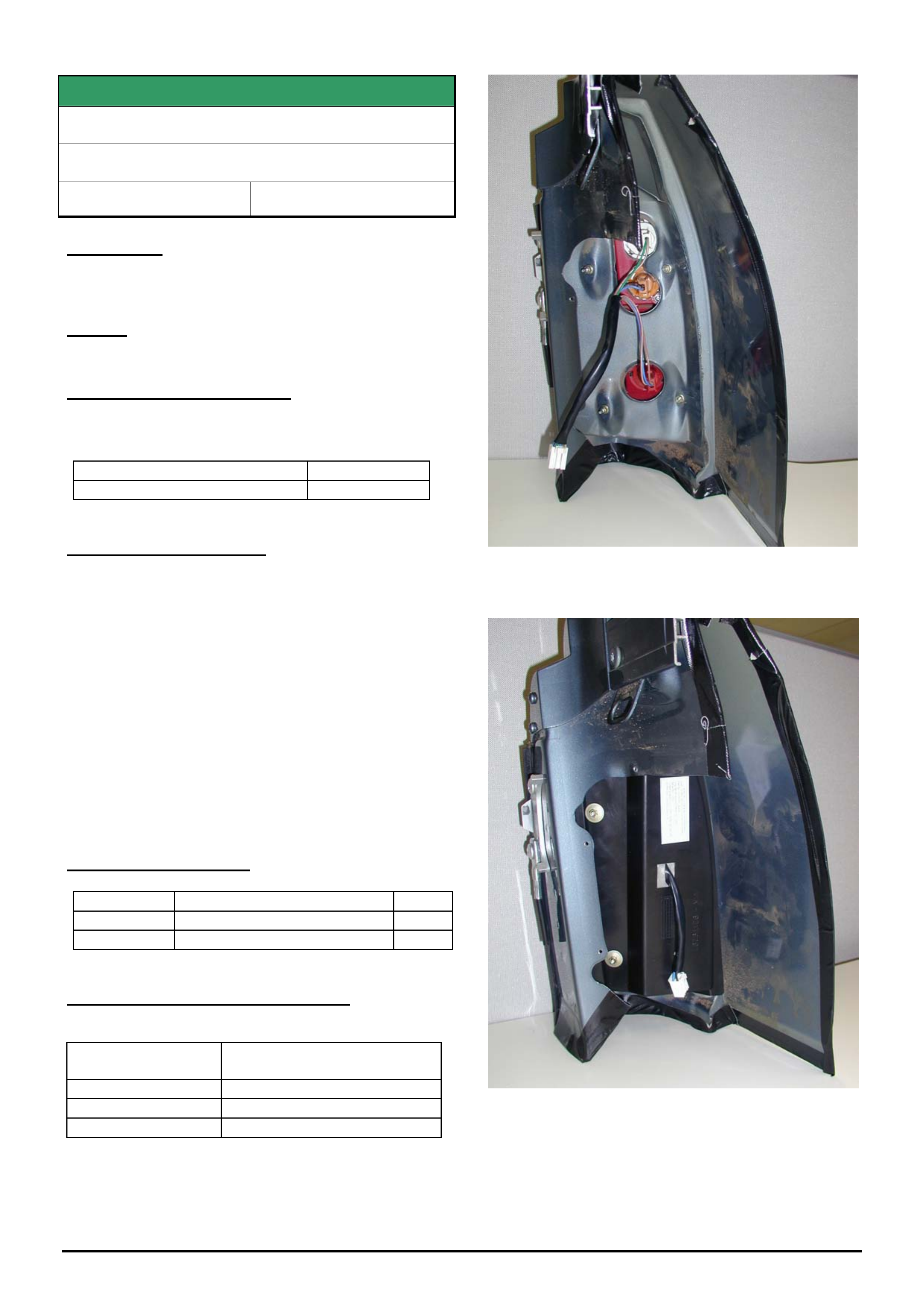
HOLDEN SERVICE TECHLINE ___________________________________________________________________________SEPTEMBER, 2005
6
Holden Techlines are written to inform technicians of conditions that may occur on some vehicles, and to provide information that could assist in the
proper service fix of a vehicle. If a condition is described, do not assume the service fix applies to a vehicle or that the vehicle will have that condition.
SERVICE FIX
Dust Entry Into Tail Lamps
VY,VZ Crewman
Group 12 Ref. No. TL0946 - 0508
CONDITION
Dust and bugs may enter the tail lamp through the vent
hole in rear of lamp.
CAUSE
Inadequate sealing .
CORRECTION – Production
Rear lamps with dust shields have been fitted to
vehicles from:
ISOVIN: Built Date:
**********L486157 10/8/05
CORRECTION – Service
Install dust shields to both sides as follows.
1. Remove inspection cover from inside the rear tub.
2. Remove foam filled plastic bag.
3. Remove the two inboard (closest to centre of
vehicle) tail lamp retaining nuts.
4. Disconnect the wiring harness.
5. Install the dust shield into position ensuring the
wiring harness is pulled through the centre of the
dust shield.
6. Refit the two retaining nuts.
7. Reconnect the tail lamp wiring harness.
8. Reinstall foam filled plastic bag
9. Reinstall inspection cover.
PARTS INFORMATION
Part No.: Partfinder Name Qty:
92179296 Dust shield RH 1
92179297 Dust shield LH 1
WARRANTY CLAIM INFORMATION
Description Install Dust shields Both
sides
Labour Op. No. N000490
Time 0.4 hr
Failure Code N0012 Foreign material
Figure 1. Cutaway view showing LHS lamp without
dust shield.
Figure 2. Cutaway view showing LHS lamp with dust
shield installed

HOLDEN SERVICE TECHLINE ___________________________________________________________________________SEPTEMBER, 2005
7
Holden Techlines are written to inform technicians of conditions that may occur on some vehicles, and to provide information that could assist in the
proper service fix of a vehicle. If a condition is described, do not assume the service fix applies to a vehicle or that the vehicle will have that condition.
SERVICE FIX
Starter Motor Engagement Problems
VZ, WL with Gen III engine
Group 12 Ref. No. TL0926 - 0508
CONDITION
Customers may advise of intermittent starter motor
engagement or starter motor “machine gunning” similar
to the vehicle having a flat battery.
CAUSE
This condition may be caused by Electrical Static
Discharge (ESD) damaging the PIM.
CORRECTION – Production
A revised PIM with increased ESD protection has been
fitted to vehicles from:
CORRECTION – Service
If this problem is intermittent it may be difficult to
reproduce, discuss the symptom with the customer to
ensure the problem was not caused by low battery
charge then replace the PIM with the revised part.
PARTS INFORMATION
Part No.: Partfinder Name Qty:
92184307 Powertrain Interface Module 1
WARRANTY CLAIM INFORMATION
Use Labour Times information in Warranty Information
section of current PV SIP CD
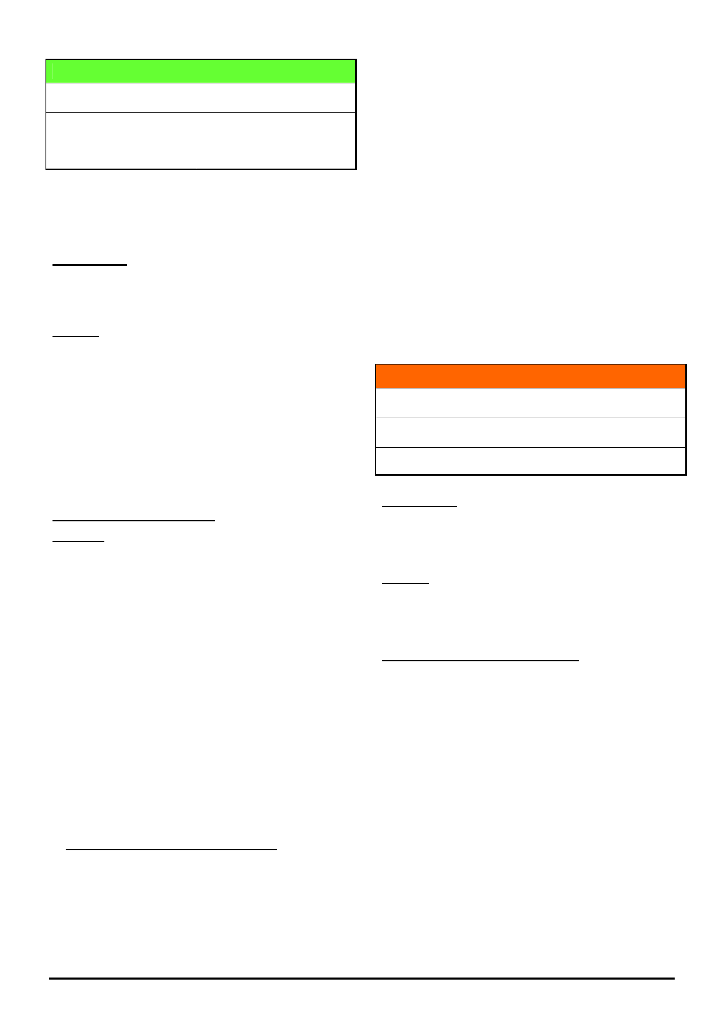
HOLDEN SERVICE TECHLINE ___________________________________________________________________________SEPTEMBER, 2005
10
Holden Techlines are written to inform technicians of conditions that may occur on some vehicles, and to provide information that could assist in the
proper service fix of a vehicle. If a condition is described, do not assume the service fix applies to a vehicle or that the vehicle will have that condition.
DIAGNOSIS HINT
ESP Early intervention
VZ & WL with ESP
Group 5 Ref. No. TL0944A - 0508
This Techline supercedes the previous one (TL0944-
0506) in Issue 6, July, 2005. It is revised by the
addition of a 15 min. drive to reinitialise the ABS
module.
CONDITION
Customer complains that the ESP is activating
unnecessarily. A buzz from the ABS module is heard
during this event.
CAUSE
The above condition may be caused by incorrect
centralisation of the steering gear where the SAS
(Steering Angle Sensor) is calibrated to this “off
central” point.
NOTE. When investigating this condition the service
technician will need to determine if the customer
complaint is a normal or an abnormal ESP event. For
information which may help to determine this, refer to
Techline No.TL0980-0508 in Issue 8, 2005.
RECOMMENDED ACTION
Summary: Centralise the steering gear, adjust toe and
steering wheel to new central point and recalibrate the
steering angle sensor (SAS). The relevant procedures
are as follows.
1. Verify the position of the steering gear using tech 2. In
the ABS data list monitor the SAS position from the
zero (0°) position. With the engine idling turn the
steering wheel to lock one side and note the reading
(The steering wheel will have to be turned very firmly
against the rack lock stop to get the maximum travel
reading) . Turn the wheel back to centre (0°) and now
turn wheel to lock in the other direction and note the
reading. The difference from side to side can be no
more than 8°. Total travel from lock to lock should add
up to approximately 1000°. Note the total travel
reading that can consistently be achieved.
2. If the reading difference from side to side is greater
than 8°, proceed to locate the steering gear central
point and recalibrate the SAS as follows.
3. Centralise the steering gear position. This can be
done with tech 2, once again monitoring the SAS
reading. Using the above noted total travel reading
divide this by 2, and this will be the central point from
lock either side of travel.
4. Turn the wheel to lock on one side, note the SAS
reading, turn the steering back towards centre by the
amount determined in step 3. This now should be the
central position of the steering rack. Confirm by turning
the wheel to the opposite lock and check that there is
an equal amount of travel in each direction.
5. The toe will now have to be adjusted around this
central rack position.
6. The steering wheel will also have to be moved to suit
this central rack position.
7. The steering angle sensor will need to be recalibrated
so that the central rack position is set to 0°. Refer to
procedure in PV SIP.
8. FINALLY, the vehicle will need to be driven on the
road for approximately 15 minutes to reinitialise the
ABS module.
INFORMATION
Electronic Stability Program (ESP) Operation
VZ & WL with ESP
Group 5 Ref. No. TL0980 - 0508
CONDITION
Customer reports a loud buzz from under the bonnet
on corners at medium to low speed.
CAUSE
The above condition is normal operation of the ABS
module during an ESP event.
SERVICE RECOMMENDATION
To relieve any customer concern about the noise we
suggest you verify that the steering gear is centralised
as per Service Techline TL0944A-0805 in Issue 8,
2005. After verifying this, and the condition still exists,
explain to the customer that during an ESP event the
ABS module will cycle and a buzz can be heard.
This should be explained in conjunction with reference
to the information on ESP in the owners handbook.
ESP can intervene during a wide range of conditions. It
is not limited to high speed wet conditions and while
the customer may consider it not necessary, it is doing
its job as per design intent.
Confirmation of normal operation by comparing the
customers vehicle to another must be done with a
vehicle of the same level. i.e Acclaim compared with
Acclaim. This is due to the calibration being different
for each level vehicle where Acclaim is different to
Calais and different again to Statesman.
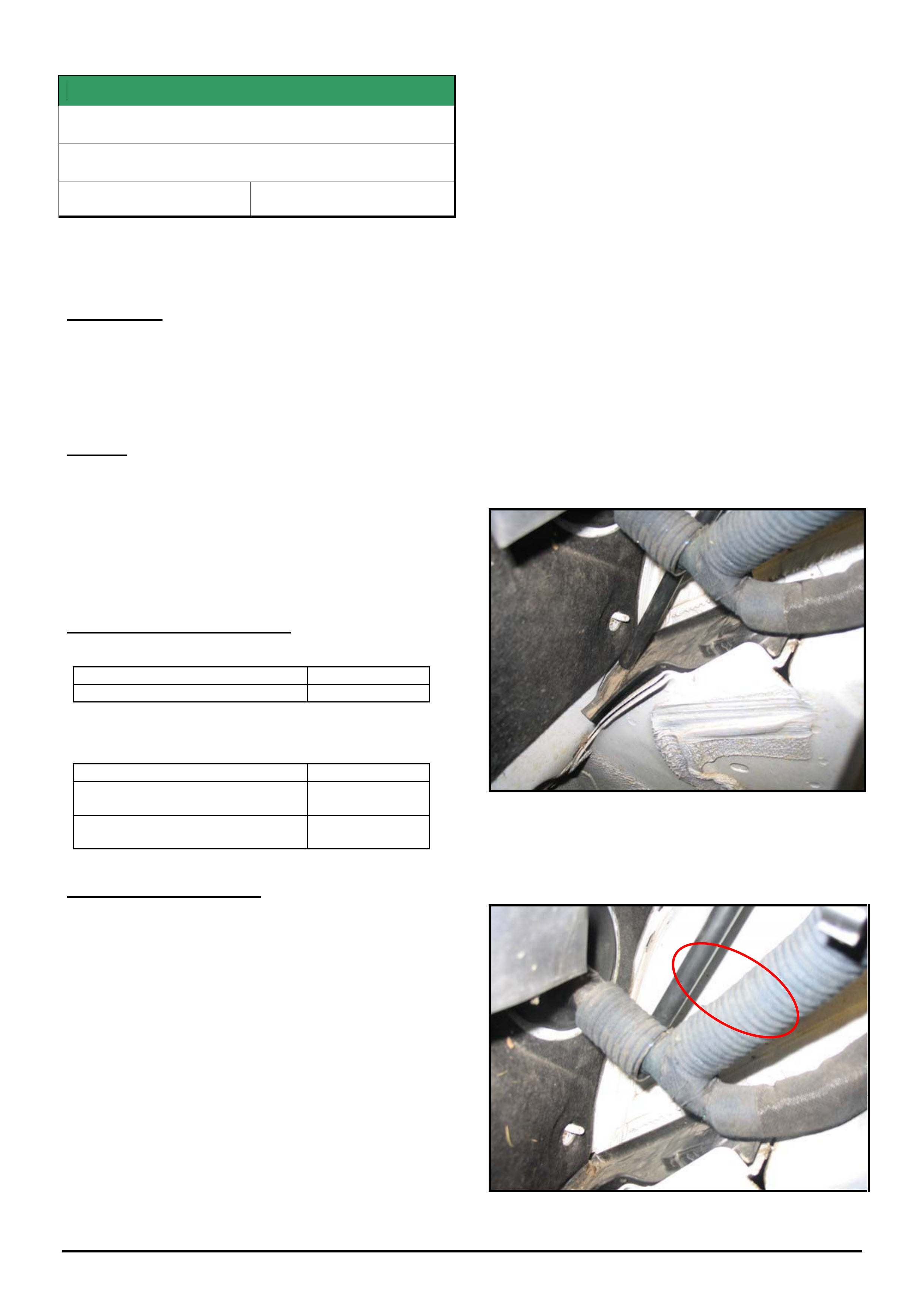
HOLDEN SERVICE TECHLINE ___________________________________________________________________________SEPTEMBER, 2005
11
Holden Techlines are written to inform technicians of conditions that may occur on some vehicles, and to provide information that could assist in the
proper service fix of a vehicle. If a condition is described, do not assume the service fix applies to a vehicle or that the vehicle will have that condition.
SERVICE FIX
DTC’s P0700, P0715, P0720
ZC with A/T
Group 7B Ref. No. TL0737A - 0508
This Techline supercedes TL0737- 0501 published in
Issue 1, Feb. 2005. Please cross out all copies of
that techline.
CONDITION
Customer may complain of “no shifting” or “incorrect
shifting” of transmission ratios.
One or all of the following DTC’s may be stored:
P0700, P0715 or P0720
CAUSE
There are 2 possible causes for the above condition.
1. Moisture may have entered the speed sensor
connector, causing an incorrect or interrupted signal.
2. Coolant may have entered the transmission via the
radiator oil cooler
CORRECTION – Production
1. Protective grease applied to speed sensors from:
Trans. Serial No.: Built Date:
03MV735125 06/01/04
2. Radiators with revised oil cooler sealing were
introduced into vehicle production from:
ISOVIN: Built Date:
Ellesmere Port:
W0L0ZCF6848035197
not available
Russelsheim
W0L0ZCF3541042598
not available
CORRECTION – Service
1. Disconnect the speed sensor connector and dry
out any moisture present.
2. If there is no evidence of corrosion or damage to
terminals apply grease p/n 09163339 to connector
to stop future moisture entry.
3. If corrosion or damage is evident, replace the
sensor and/or connector as required. Also apply
grease 09163339 to connector to stop future
moisture entry.
4. Remove transmission valve body cover
CAREFULLY and inspect for possible coolant
entry to transmission via the radiator oil cooler. If
there is evidence of moisture contamination,
proceed to step 5. If there is no evidence of
moisture contamination, no further action is
required.
5. If the vehicle ISOVIN is prior to those shown in the
Production Correction table, replace the radiator.
If ISOVIN is after those shown, pressure check
radiator. If radiator fails pressure test, replace
radiator then go to step 6. If radiator passes
pressure test, proceed to step 7.
6. Flush the transmission to remove traces of
water/coolant contamination. The transmission
can be flushed using a commercial flushing unit or
as follows.
Disconnect the transmission to radiator oil cooler
line and drain into a suitable container. With
engine idling and A/T in Neutral, flush approx 10 to
12 litres of the specified trans. fluid through the
transmission. After flushing, reconnect cooler line
and check fluid level is correct.
7. Check the routing of the transmission breather
hose. The breather hose outlet must not be
located in the plastic gutter that drains A/C
condensate. Refer Figure 1.
Figure1 – Breather hose incorrectly located.
8. Relocate the breather hose so that it is clear of the
drain channel as shown in Figure 2. Secure hose
to conduit with tie straps as required.
Figure 2. Relocated A/T breather hose

HOLDEN SERVICE TECHLINE ___________________________________________________________________________SEPTEMBER, 2005
12
Holden Techlines are written to inform technicians of conditions that may occur on some vehicles, and to provide information that could assist in the
proper service fix of a vehicle. If a condition is described, do not assume the service fix applies to a vehicle or that the vehicle will have that condition.
PARTS INFORMATION
Part No. Description Qty
09163339 Grease. NYOGEL 760G -
25 gm tube
1
93173888 speed sensor 1
93160393 Automatic transmission oil
1 litre (Esso ATF 3309)
WARRANTY CLAIM INFORMATION
Refer to your District Aftersales Manager.
DIAGNOSIS HINT
DTC P0704 Clutch Switch Input High
AH, TS, XC, JS, Fitted with M/T
Group 7A Ref. No. TL0990 - 0508
PROBLEM DESCRIPTION
Customers may advise that intermittently the check
engine light illuminates and after the ignition is cycled
the light goes out.
Initial checks reveal the only DTC that may be set is a
history P0704 (Clutch Switch Input High).
If, after checking the clutch switch circuit and switch
operation including adjustment as per TIS 2000, no
fault is found, the problem is probably induced by the
driver.
CAUSE
The driver may be accelerating up through the gears
and then decelerating again without completely lifting
their foot off the clutch, meaning the ECU does not see
the “clutch status” input change as the vehicle
accelerates, (This can be seen with Tech 2 in ECU
data).
DTC P0704 sets when the ECU sees the vehicle
accelerate to above approximately 57km/h then come
to a stop several times without the clutch switch input
changing. This is most likely to happen in heavy traffic
together with the driver resting their foot on the clutch.
CORRECTION
After verifying that clutch switch operation and
adjustment is correct, customers need to be made
aware that their driving habit is the likely factor for
inducing this fault.
Do not replace engine ECU’s and/or clutch
switches for this condition.
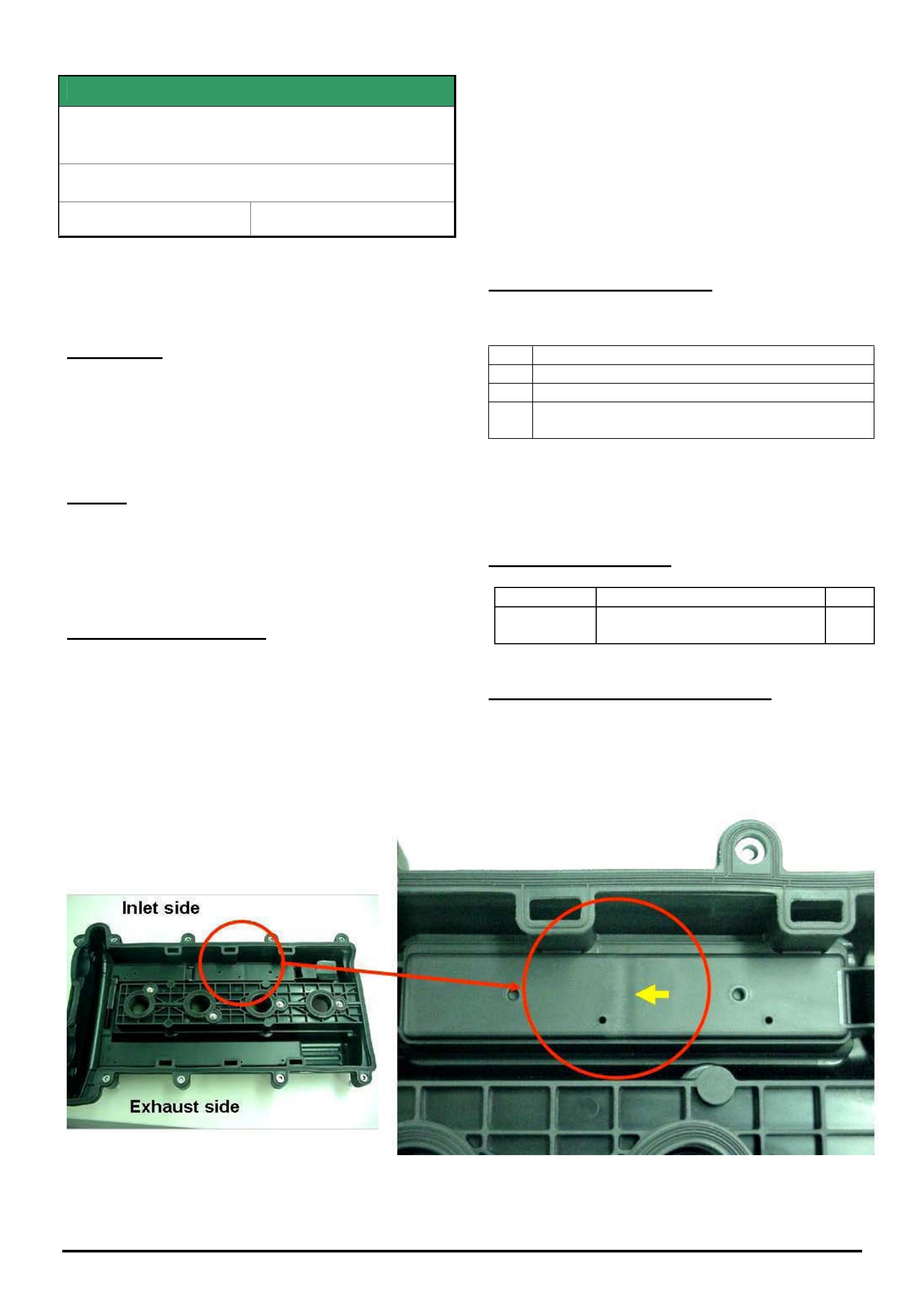
HOLDEN SERVICE TECHLINE ___________________________________________________________________________SEPTEMBER, 2005
13
Holden Techlines are written to inform technicians of conditions that may occur on some vehicles, and to provide information that could assist in the
proper service fix of a vehicle. If a condition is described, do not assume the service fix applies to a vehicle or that the vehicle will have that condition.
SERVICE FIX
Excessive Engine Oil Consumption Due To
Faulty Cylinder Head Cover (Plastic Type)
ZC, TS, TT, all with Z22SE engine
Group 6A Ref. No. TL0807A - 0508
This Techline supercedes TL0807-0504 published in
Issue 4, May, 2005. It is revised by clarifying
replacement requirements - as some technicians are
incorrectly replacing cam covers that have no defect.
CONDITION
Some customers may report that their vehicle exhibits
the following symptoms;
1) Blue smoke coming from the exhaust and/or
2) High oil consumption
CAUSE
Positive crankcase ventilation passages within the
plastic cylinder head cover may not be to specification.
NOTE: The metal cylinder head covers are not
affected.
CORRECTION – Service
1. Confirm the customer complaint by conducting
a standard oil consumption test.
2. If vehicle has high oil consumption, proceed to
check the cylinder head cover for a possible
manufacturing fault described as follows.
3. Remove the cylinder head cover and inspect the
underside of the cover. A faulty cover can be identified
by a “sink” mark which is clearly evident as shown in
Figure 1.
4. A faulty cover should be replaced with a new
cover from HSPO. (If cover is not faulty contact TAS
for further advice). For removal and replacement
procedure refer to TIS 2000.
CORRECTION – Production
Known OK covers have been fitted to all vehicles from:
ISOVIN:
ZC *********51010110
TT *********4H004812
TS *********5B000136 - Convertible
*********45123695 - SRi excluding turbo
NOTE: All plastic covers in vehicles with lower
ISOVIN’s should be inspected when required, and
only replaced if the defect exists.
PARTS INFORMATION
Part No.: Partfinder Name Qty:
13113034 Cover, cylinder head (plastic)
includes gasket and fasteners
1
WARRANTY CLAIM INFORMATION
Use Labour Times information in Warranty Information
section of current PV SIP CD
NOTE: Cam covers replaced that show no defect
will NOT be accepted under warranty.
Figure 1. A faulty cover will have a sink mark shown at position of yellow arrow
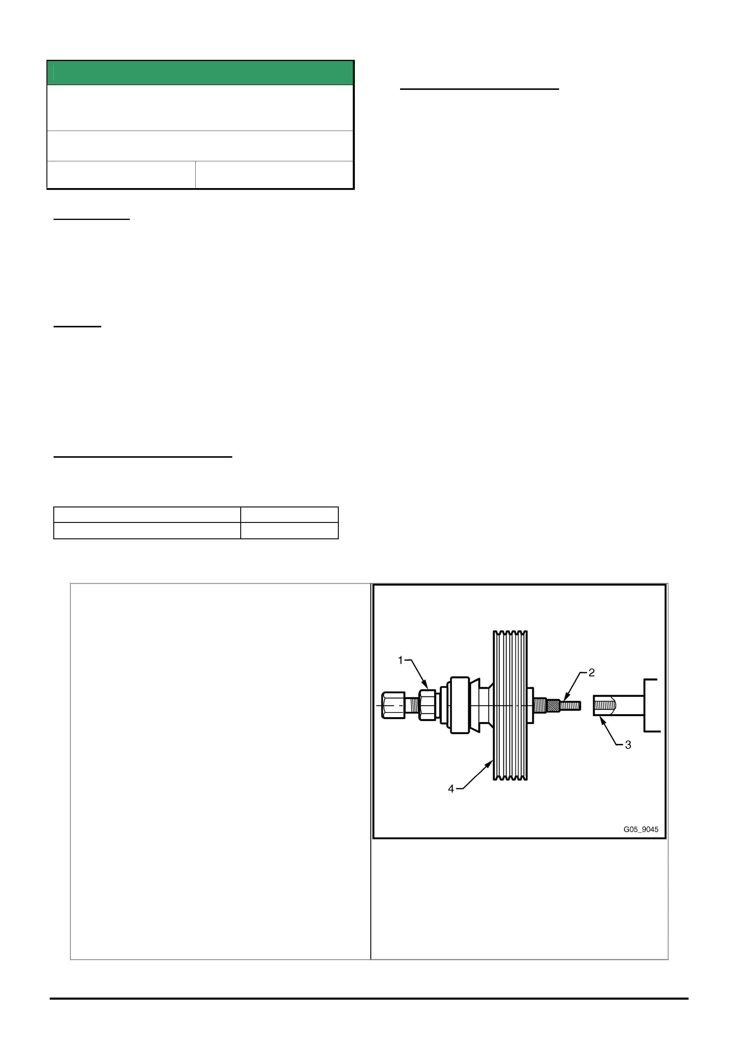
HOLDEN SERVICE TECHLINE ___________________________________________________________________________SEPTEMBER, 2005
14
Holden Techlines are written to inform technicians of conditions that may occur on some vehicles, and to provide information that could assist in the
proper service fix of a vehicle. If a condition is described, do not assume the service fix applies to a vehicle or that the vehicle will have that condition.
SERVICE FIX
Drive Belt Squeal, Power Steering Pump
Pulley Misalignment
VZ & WL with HFV6 engine
Group 6A Ref. No. TL0985 - 0508
CONDITION
Squeaking noise from engine bay at idle and while
driving. On closer examination the squeaking noise
can be heard coming from where the accessory belt
rubs on the flange of the power steering pump pulley.
CAUSE
The root cause of this condition may be traced to
misalignment of the power steering pump pulley with
the crank pulley and alternator pulley. Investigation of
cases of misalignment has shown that the pump
pulley hub has not been pressed far enough onto the
pump shaft.
CORRECTION – Production
Vehicles with power steering pump pulleys installed
to the correct alignment were built from:
ISOVIN: Built Date:
**********L468921 30/06/05
CORRECTION – Service
In the event of the above condition being
experienced, inspect the position of the power
steering pump pulley on the power steering pump
shaft.
Correct location is for the hub of the pulley to be flush
with the end of the pump shaft within 0.3 mm.
If the face of the pulley hub is found to overhang the
end of the pulley shaft by greater than 0.3 mm
(.012”), the pulley should be pressed further on to the
shaft so that the face of the pulley hub is flush with
the end of the pump shaft.
The procedure to be used is shown in Holden SIP,
Chapter 9 - Steering, Section 3.12,. which is
reproduced below.
NOTE. The final test as to whether the pulley is
located correctly is to use a straight edge to check
the alignment of the drive belt pulleys. This
procedure was published in techline in Issue 5, 2001
- Group 6A titled “Gen 3 V8 ENGINE DRIVE BELT
SQUEAL”.
1 Assemble the drive nut (1) and thread insert (2) into
the forcing screw of Tool 7005. Ensure that adequate
graphite grease is applied to the forcing screw and
nut.
2 Tighten the forcing screw assembly by hand onto the
pump shaft (3), until it bottoms out against the
shoulder.
NOTE
Do not use a spanner for this operation.
3 Turn the drive nut against the pulley (4) until the pulley
is at the correct installation depth.
NOTE
Do not allow the forcing screw to turn during this
operation. Do not use power tools or exceed a
torque of 90.0 Nm. If the pulley cannot be
installed within this torque, replace the complete
pump assembly.
4 Once the pulley is installed, remove the forcing screw
from the pump shaft.
5 Install the power steering pump, refer to 3.12 Power
Steering Pump.
Figure 9 – 155

HOLDEN SERVICE TECHLINE ___________________________________________________________________________SEPTEMBER, 2005
15
Holden Techlines are written to inform technicians of conditions that may occur on some vehicles, and to provide information that could assist in the
proper service fix of a vehicle. If a condition is described, do not assume the service fix applies to a vehicle or that the vehicle will have that condition.
SERVICE FIX
EGR Malfunction, DTC P0400 Sets
XC Combo (Z16SE Engine)
Model Years 2003 & 2004 Only
Group 6C Ref. No. TL0941A - 0508
This Techline supercedes TL0941- 0506 published in
Issue 6, JUL 05. Please cross out your copy of that
techline .
CONDITION
Drivers may complain of: engine running ‘rough’ and/or
may in isolated cases stall at very low speeds during
this ‘rough running’ period, and engine check lamp
illuminates.
Technicians may find a DTC P0400 set.
CAUSE
Deposits of contaminants built up between the EGR
pintle and its guide causing the pintle to seize.
CORRECTION
If diagnosis leads to an EGR malfunction and DTC
P0400 is logged, proceed as follows.
MODEL YEAR 2003 VEHICLES.
The service fix action detailed below MUST NOT be
applied to MODEL YEAR 2003 vehicles until TIS CD
64 becomes available.
Until then, if a 2003 vehicle has an EGR
malfunction, replace the EGR valve and reprogram
the engine ECU using TIS CD 51 or earlier to CD
40.
Failure to comply with this may induce problems
with the cooling fans which could cause the engine
to overheat under certain driving conditions.
MODEL YEAR 2004 VEHICLES.
Step 1. - Check position of the EGR Valve.
The position of the EGR valve can be found by
performing the 'Actuator test' with TECH 2, selected as
follows:
Diagnostics,
Model Year,
Vehicle Type,
Engine,
Actuator test,
EGR Solenoid test,
EGR position Feedback.
(1a). If the EGR position feedback is between 0.15V
and 1.5V after performing the test (Test Status:
Inactive) the EGR valve is closed - Go to Step 2.
(1b). If the EGR position feedback is higher than
1.5V after performing the actuator test (Test Status:
Inactive) the EGR valve is not completely closed and
should be replaced with a new one from HSPO.
Perform the actuator test again when the new
valve is installed to ensure the valve closes fully.
Once confirmed, proceed to step 2.
Step 2. - Reprogram ECU.
Reprogram the ECU with modified software,
available from TIS CD 61 and onward, to deactivate
the EGR function.
The correct hardware number and revised ECU
software part numbers are listed below.
Step 3. - Vehicle Marking
All vehicles that are modified according to the above
information are required to be clearly marked by a
yellow paint dot on the upper side of the EGR valve
housing. This will alert service technicians that the
engine management system has been revised and
the EGR is disabled.
WARRANTY CLAIM INFORMATION
Use Labour Times information in Warranty
Information section of current PV SIP CD
Update

HOLDEN SERVICE TECHLINE ___________________________________________________________________________SEPTEMBER, 2005
16
Holden Techlines are written to inform technicians of conditions that may occur on some vehicles, and to provide information that could assist in the
proper service fix of a vehicle. If a condition is described, do not assume the service fix applies to a vehicle or that the vehicle will have that condition.
INFORMATION
Engine ECU Cannot Be Linked To Immobiliser
All Holden vehicles with programmable ECU’s
– TS, ZC, AH
Group 6C Ref. No. TL0961- 0508
CONDITION
Dealers report that they cannot link the engine ECU
and the immobiliser after fitting a replacement engine
ECU from spare parts.
CAUSE
To link the immobiliser to a new engine ECU (from
spare parts) the immobiliser must be able to
communicate with the engine calibration. As new
engine ECU’s from spare parts are blank (i.e. they do
not contain any engine information) they cannot be
linked to an immobiliser until they are SPS
programmed.
CORRECTION
A summary of the correct steps in replacing an engine
ECU are as follows.
• Reset the original engine ECU prior to removing.
• Install new ECU.
• Program new ECU with the correct engine
calibration. (use SPS programming)
• Link the ECU and immobiliser.
TS Astra - the linking is done via the immobiliser.
AH & ZC - the linking is done via the engine ECU
Procedure for TS Astra.
1. Obtain the security number.
2. Reset the original ECU with Tech 2 as follows:
1. F0 Diagnosis
2. F3 Body / immobiliser
3. F3 Additional Functions
4. F2 Reset Engine Control Unit
5. Enter Security Code
6. Press OKAY if correct security code has been
entered
7. The following warning will appear: “Warning
Engine will not start after reset”
8. Programming Completed.
3. Remove original ECU and install the new ECU and
proceed as follows.
1. F1 Service Programming system (SPS)
2. F0 Request Info. When finished, disconnect
Tech 2 from vehicle and go to your PC that has
TIS installed. Select Service Programming
System and download the new calibration for that
vehicle. Return to the vehicle and download the
new calibration into the new ECU.
To link the new ECU to the vehicle proceed as follows:
3. F0 Diagnosis.
4. F3 Body / Immobiliser.
5. F4 Programming
6. F0 Program Immobiliser Function
7. Get programming approval from TIS. Once
approval has been obtained, return to
programming immobiliser function.
8. Enter the correct Engine type
9. Engine controller installed.
10. Perform the CAN and VARIANT configuration,
in ECU programming menu.
11. Follow the remaining Tech 2 instructions.
Procedure for AH Astra and ZC Vectra
1. Obtain the security number.
2. Reset the original ECU with Tech 2 as follows:
1. F0 Diagnostics
2. Model year
3. Vehicle
4. Engine
5. Type (ie; Z18XE)
6. Programming
7. Reset ECU
3. Remove original ECU and install the new ECU and
proceed as follows.
1. F1 Service Programming system
(SPS)
2. F0 Request Info. When finished, disconnect
Tech 2 from vehicle and go to your PC that
has TIS installed. Select Service
Programming System and download the new
calibration for that vehicle. Return to the
vehicle and download the new calibration into
the new ECU.
To link the new ECU to the vehicle proceed as follows:
4. Link the new ECU with Tech 2 as follows:
1. F0 Diagnostics
2. Model year
3. Vehicle
4. Engine
5. Type (ie; Z18XE)
6. Programming
7. Link ECU
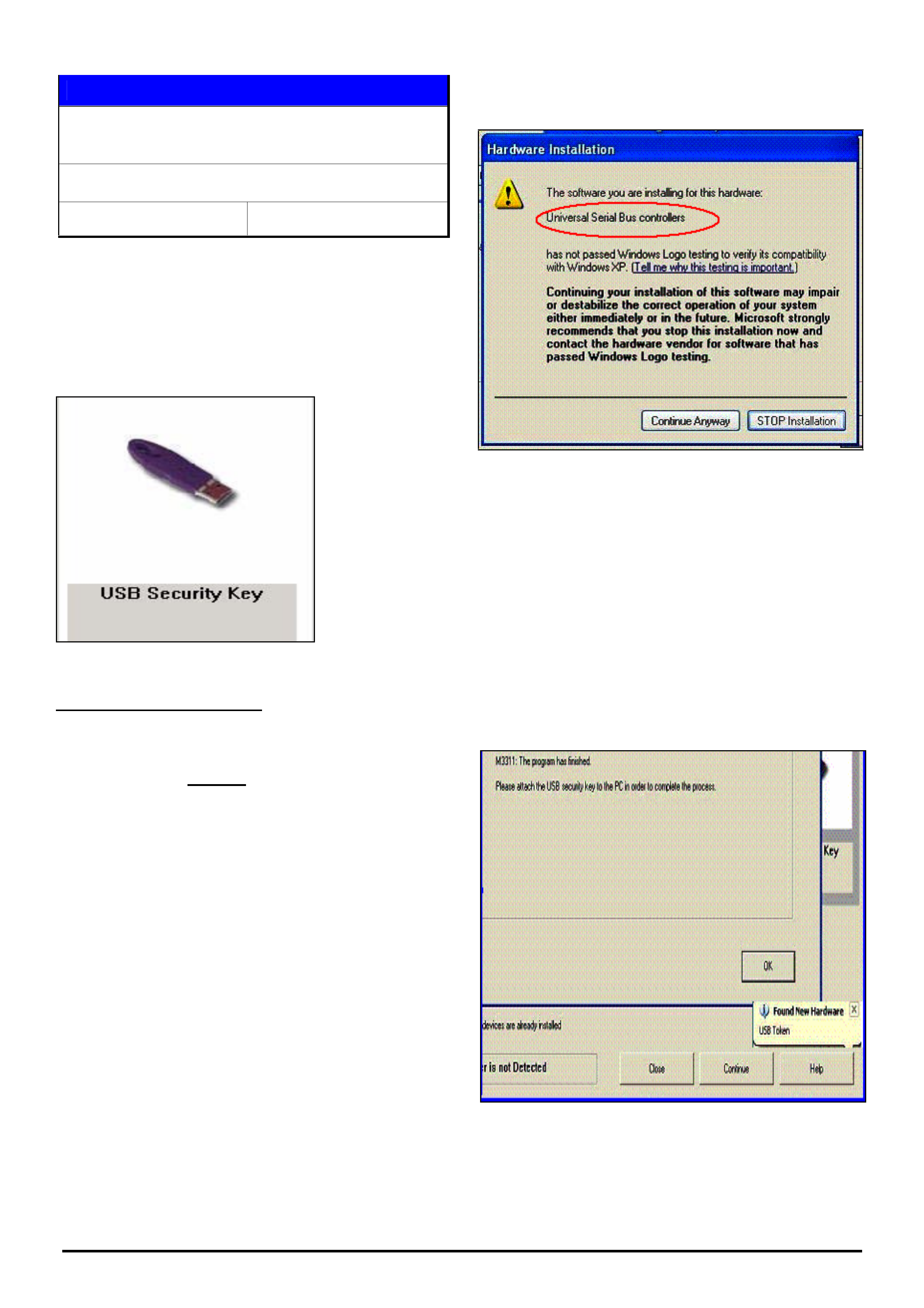
HOLDEN SERVICE TECHLINE ___________________________________________________________________________SEPTEMBER, 2005
17
Holden Techlines are written to inform technicians of conditions that may occur on some vehicles, and to provide information that could assist in the
proper service fix of a vehicle. If a condition is described, do not assume the service fix applies to a vehicle or that the vehicle will have that condition.
SERVICE PROCEDURE
Installation Procedure for USB Super Pro
Hardware Key
TIS 2000
Group OB Ref. No. TL0988-0508
In order for a new USB (universal serial bus)
hardware key (refer figure 1) to work the
appropriate system driver must be installed. This
techline is based on Windows XP but other
systems should be similar although screen shots
and messages may differ.
Figure 1
Unsuccessful Installation
If the dealer has already performed an
unsuccessful installation of the system driver,
please start with Step 8 and check the entry in the
Device Manager. From there, proceed back to
Step 1.
Step 1 - New Installation
Do NOT insert the USB hardware key until
prompted by TIS2000!
To install the system driver in TIS 2000:
• start TIS 2000
• select the ‘Configuration’ menu at top of screen
then ‘Security Device System Driver’
• click on the box for 'Click here to add'
• click on the button ‘Continue’
• follow the instructions in the next two pop-up
windows
You will then see the following pop-up from the
operating system:
Figure 2
Click on the button 'Continue Anyway'.
Step 2
This is the last window in TIS 2000 for the
installation process. In the lower right corner you
can see that Windows XP has found a USB device
'USB Token', but is has not been recognized as
'Rainbow SuperPro' (refer figure 3). Some
operating systems may detect the USB device
correctly as a 'Rainbow SuperPro'. In these cases
no further action is required.
Figure 3
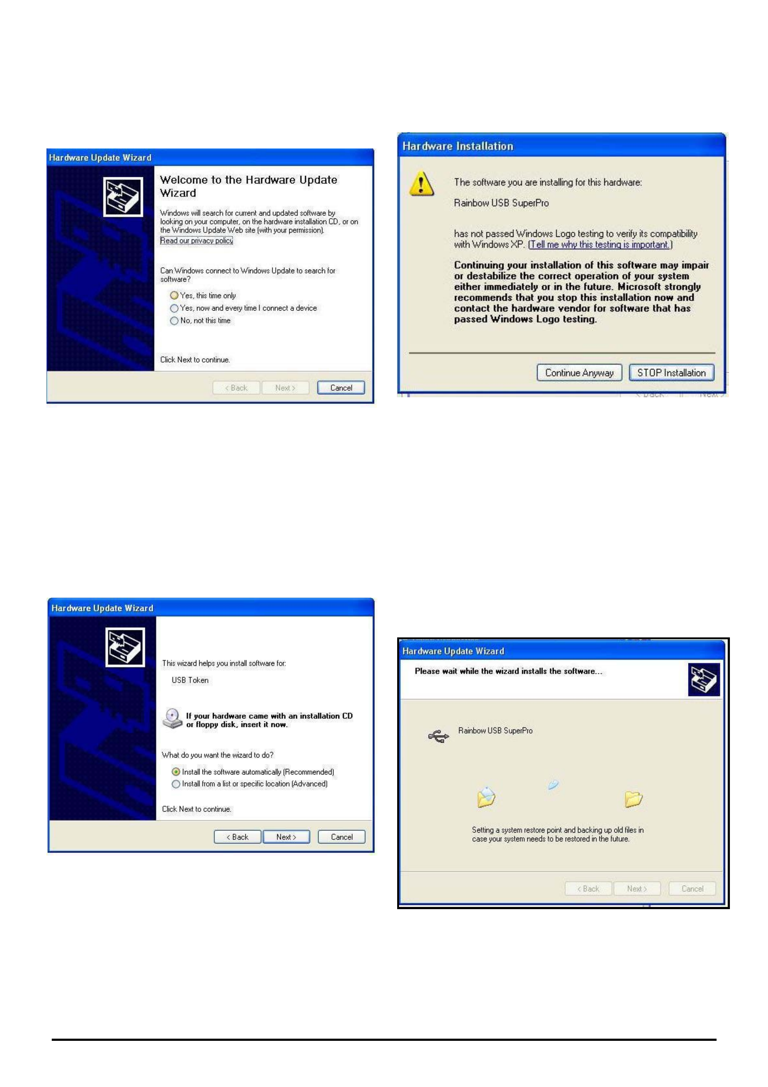
HOLDEN SERVICE TECHLINE ___________________________________________________________________________SEPTEMBER, 2005
18
Holden Techlines are written to inform technicians of conditions that may occur on some vehicles, and to provide information that could assist in the
proper service fix of a vehicle. If a condition is described, do not assume the service fix applies to a vehicle or that the vehicle will have that condition.
Step 3
A few seconds after the hardware key has been
connected to the USB port, Windows XP displays
the following window:
Figure 4
• select the button 'Yes, this time only'
• click on the button Next
Step 4
Figure 5
• insert CD 1 of the latest TIS version
• select 'Install the software automatically'
• click on the button Next
• the computer will search for the correct
driver on the TIS CD
Step 5
You will then see the following pop-up from the
operating system:
Figure 6
In contrast to the image at Step 1 the computer has
recognized the hardware 'Rainbow USB SuperPro'.
• click on 'Continue Anyway'
Step 6
While the correct system driver for the SuperPro
USB key is being installed, you will see the
following window: Figure 7.
Figure 7
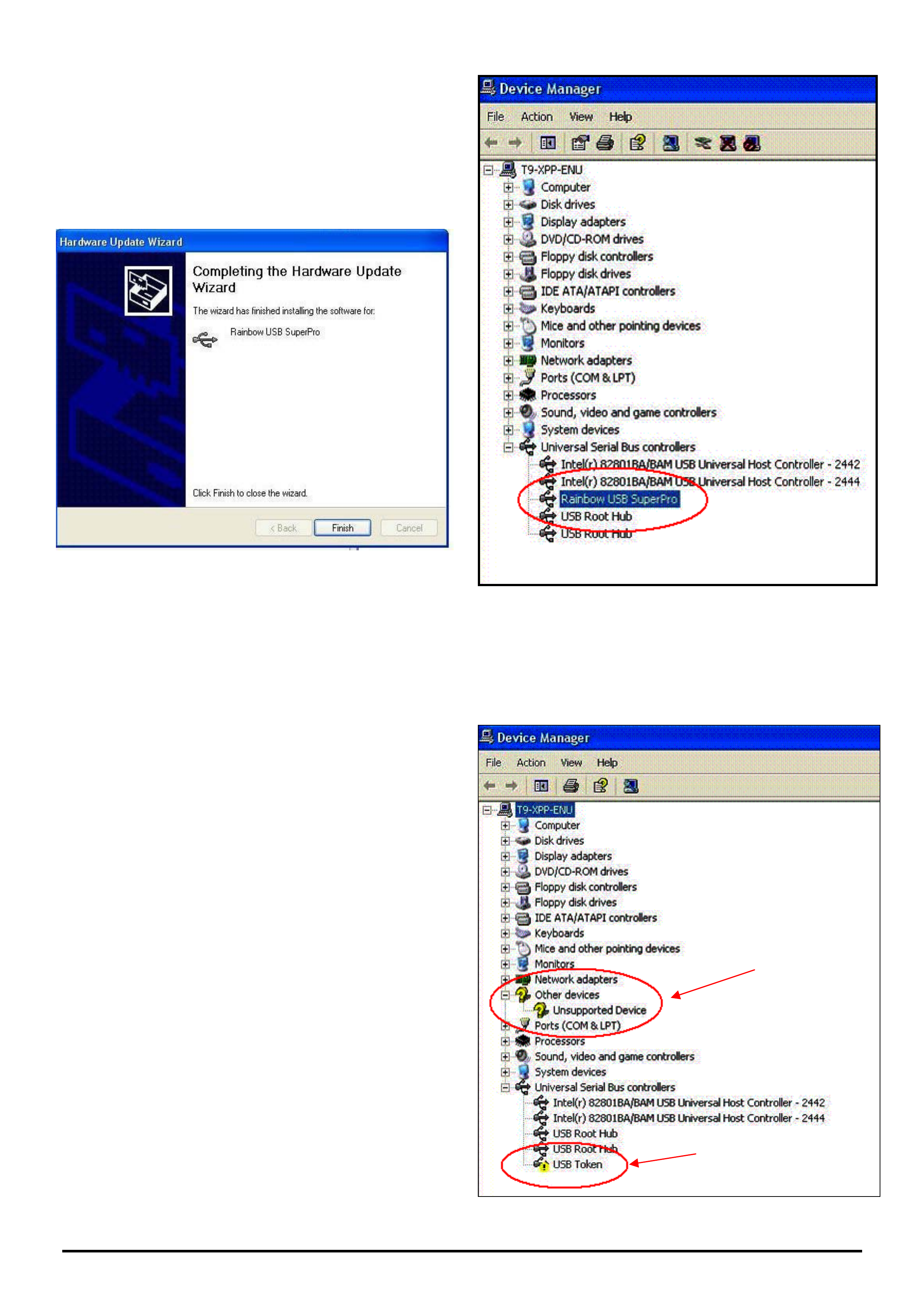
HOLDEN SERVICE TECHLINE ___________________________________________________________________________SEPTEMBER, 2005
19
Holden Techlines are written to inform technicians of conditions that may occur on some vehicles, and to provide information that could assist in the
proper service fix of a vehicle. If a condition is described, do not assume the service fix applies to a vehicle or that the vehicle will have that condition.
Step 7
This is the final window when the installation is
complete:
• click on the button 'Finish'
The set up is now finished.
Figure 8
Step 8
If the dealer has already performed an
unsuccessful system driver installation, remove the
USB hardware key then check the Device
Manager:
To open the Device Manager, click with the right
mouse button on:
• my computer (on the desktop)
• select Properties
• select Hardware
• select Device Manager
The correct entry in the Device Manager of
Windows XP will look like figure 9.
Figure 9
A wrong entry in the Device Manager may look like
this: Figure 10
Figure 10
a
b

HOLDEN SERVICE TECHLINE ___________________________________________________________________________SEPTEMBER, 2005
20
Holden Techlines are written to inform technicians of conditions that may occur on some vehicles, and to provide information that could assist in the
proper service fix of a vehicle. If a condition is described, do not assume the service fix applies to a vehicle or that the vehicle will have that condition.
Explanation of notes ‘a’ and ‘b’ from Figure 10.
a) Other devices - Unsupported Device or USB
superpro with a question mark ?
-> click on that entry with the right mouse button
and select delete or uninstall
b) USB Token or USB SuperPro with an
exclamation mark !
-> Rainbow SuperPro was not recognized.
-> the installation was not successful.
-> Click on that entry with the right mouse button
and select delete or uninstall.
After deleting the incorrect entries, go to Step 1.
Make sure the USB hardware key is NOT
connected until requested by TIS2000.
© GM Europe, SPO Engineering, International Operations - 31
July 2005
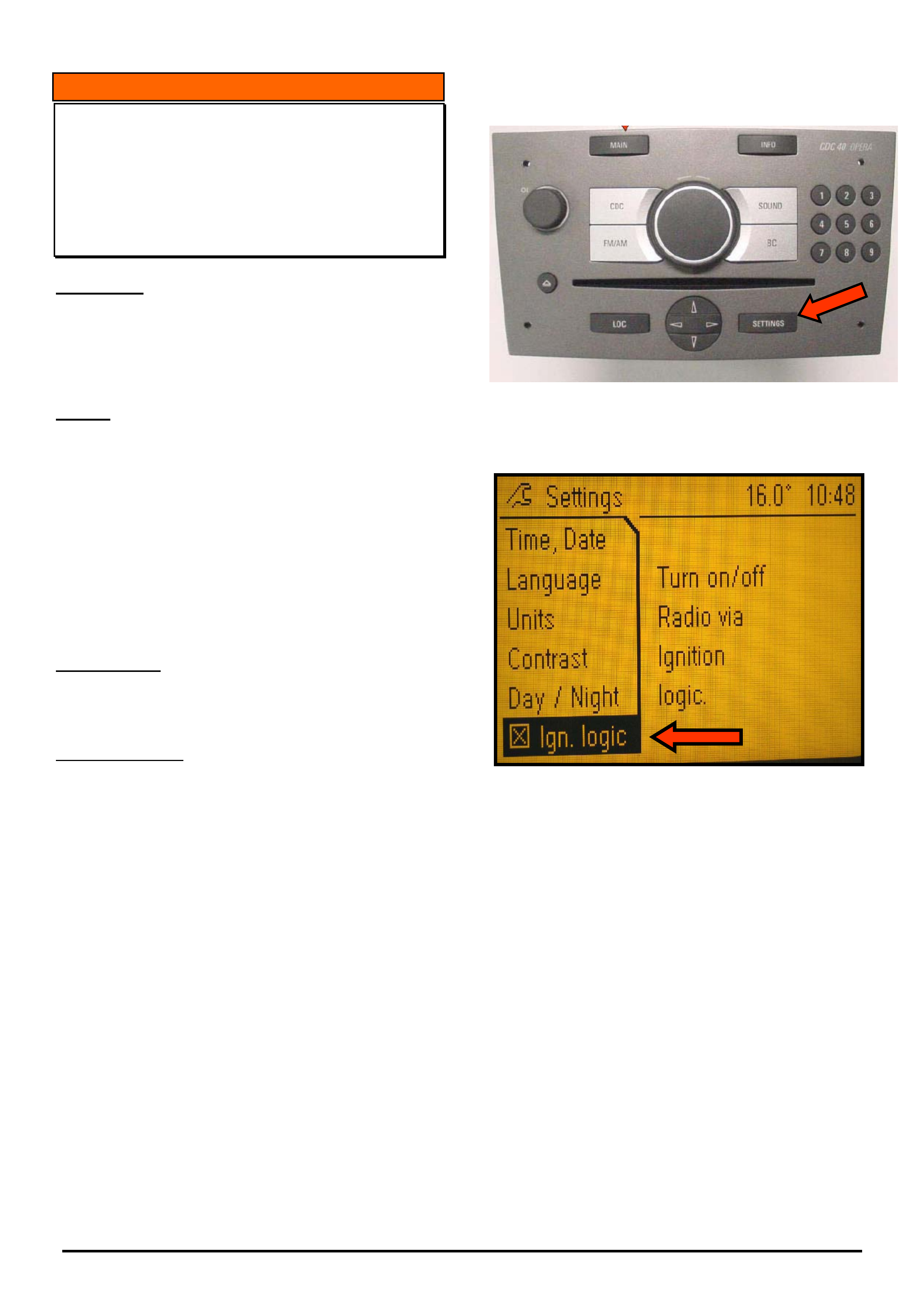
HOLDEN SERVICE TECHLINE ___________________________________________________________________________OCTOBER, 2005
9
Holden Techlines are written to inform technicians of conditions that may occur on some vehicles, and to provide information that could assist in the
proper service fix of a vehicle. If a condition is described, do not assume the service fix applies to a vehicle or that the vehicle will have that condition.
INFORMATION
Radio Stays On After Ignition/Acc Turned Off
(Ignition Key Removed)
AH, ZC, XC fitted with Blaupunkt CDC30 &
CDC40 Audio Units
(GROUP 12) TL0917-0509
CONDITION
Customers may report that their radio stays on after
the ignition is turned off and the key is removed, or the
radio can only be turned off via the on/off button on the
radio.
CAUSE
The new Blaupunkt audio units have a programming
feature where the radio can be set to turn off via the
ignition switch the conventional way, or only by the
on/off button on the audio head unit.
This new feature is called “ignition logic” programming.
The factory setting is for the radio to turn off when the
ignition key is removed from the lock.
This feature may have accidentally been changed by
the customer.
CORRECTION
If presented with a vehicle where the customer
requests the radio to turn off when the ignition key is
removed, press the “settings” button on the audio
control panel (refer Figure 1) then set the radio to
“ignition logic on” by placing an “X” in the box as
shown in Figure 2
NOTE: A CDC 40 Audio unit is displayed in Figure 1.
On CDC 30 units, the “settings” button is in a different
location.
Figure 1 - CDC 40 Opera Radio
Figure 2 - Info Display

HOLDEN SERVICE TECHLINE ___________________________________________________________________________OCTOBER, 2005
10
Holden Techlines are written to inform technicians of conditions that may occur on some vehicles, and to provide information that could assist in the
proper service fix of a vehicle. If a condition is described, do not assume the service fix applies to a vehicle or that the vehicle will have that condition.
INFORMATION
Requesting Immobiliser Security Codes
All Models
(GROUP OB) TL0936-0509
Many Dealers request immobiliser security numbers
from the Holden Vehicle Security Information Centre
for vehicles that don’t have an immobiliser or don’t
require an immobiliser number. Refer to the
following examples.
• Some variants of SB Barina, TR Astra, TF Rodeo,
and UT and MX Frontera’s do not have an
immobiliser fitted.
• VZ & WL Gen 3 vehicles have a BCM security
number but do not have an immobiliser security
number. Note that VZ & WL V6 vehicles require
an immobiliser security number.
• All YG Cruze’s require an immobiliser and BCM
number and these can be found in LCRV SIP.
As you can see from these examples, it is important
to ensure that the vehicle you are requesting security
information for actually has an immobiliser or
requires an immobiliser number.
It is therefore recommended that you check the
available Service Information for location of
components.
New Procedure For Obtaining Security Numbers.
(The following information is extracted from All
Dealer Letter 42/05 dated 19 Sep,2005.)
To obtain an immobiliser security number you MUST
FIRST check on-line via the NOW warranty system
for the information.
If the security information is not available via the
NOW system or a specific security number is not
working on a vehicle, Dealers need to fax Holden a
revised security information request form (copy on
Lionheart). It is mandatory that all fields on the form
are completed, including reference to any security
information obtained from the NOW system.
It is important to note that Holden will not be
processing security information requests that are
incomplete or on the old form. Please discard any
earlier versions of the form. Dealers are also
reminded not to fax multiple requests for the same
vehicle VIN.
Please note that TAS do not process requests for
Security Codes.
Also, there is a revised “Vehicle Security Information
Change Advice” form (copy on Lionheart). Dealers
should use this form to advise Holden of any
changes to a vehicle’s security information.
INFORMATION
Revisions to CIM, SRS Module & Drivers
Airbag
ZC Vectra
(GROUP OB) TL1000-0509
This techline is written to raise technicians
awareness of changes which have occurred to the
CIM, SRS module and Driver Airbag assemblies on
the above model.
ZC Vectra has been upgraded over the past few
model years, which has seen the introduction of
multi-stage drivers airbag. There has also been a
revised CIM and a new programming option within
the SRS module on some models.
These changes can be physically seen when
replacement of either the CIM or Airbag is carried
out, as there are TWO connectors which are fitted to
the inflator assembly. (driver airbag)
Some recent TAS cases have shown that because
incorrect CIM, SRS module or Drivers airbag part
numbers were ordered for vehicles, the result was a
lot of wasted diagnosis time and programming
difficulties being experienced.
To avoid this situation occurring, technicians should
write down the vehicle VIN and options and also
check the data list within the SRS module to
determine if the vehicle is fitted with a multi-stage
drivers airbag.
DIAGNOSIS HINT
Suspected Clunk From Driveline
VY,VZ Utility, One Tonner and Crewman
Group 4 Ref. No. TL0997- 0509
When investigating customer reports of “clunk” from
rear of vehicle at low speed during tip-in/tip-out, do
not automatically assume it is the differential or
driveline that is at fault.
Some recent cases have shown that the above
condition was not caused by the differential/driveline
but was the result of the spare wheel being loose and
moving in its mounting cradle.
In these cases the spare wheel had not been fully
raised and/or correctly inflated.
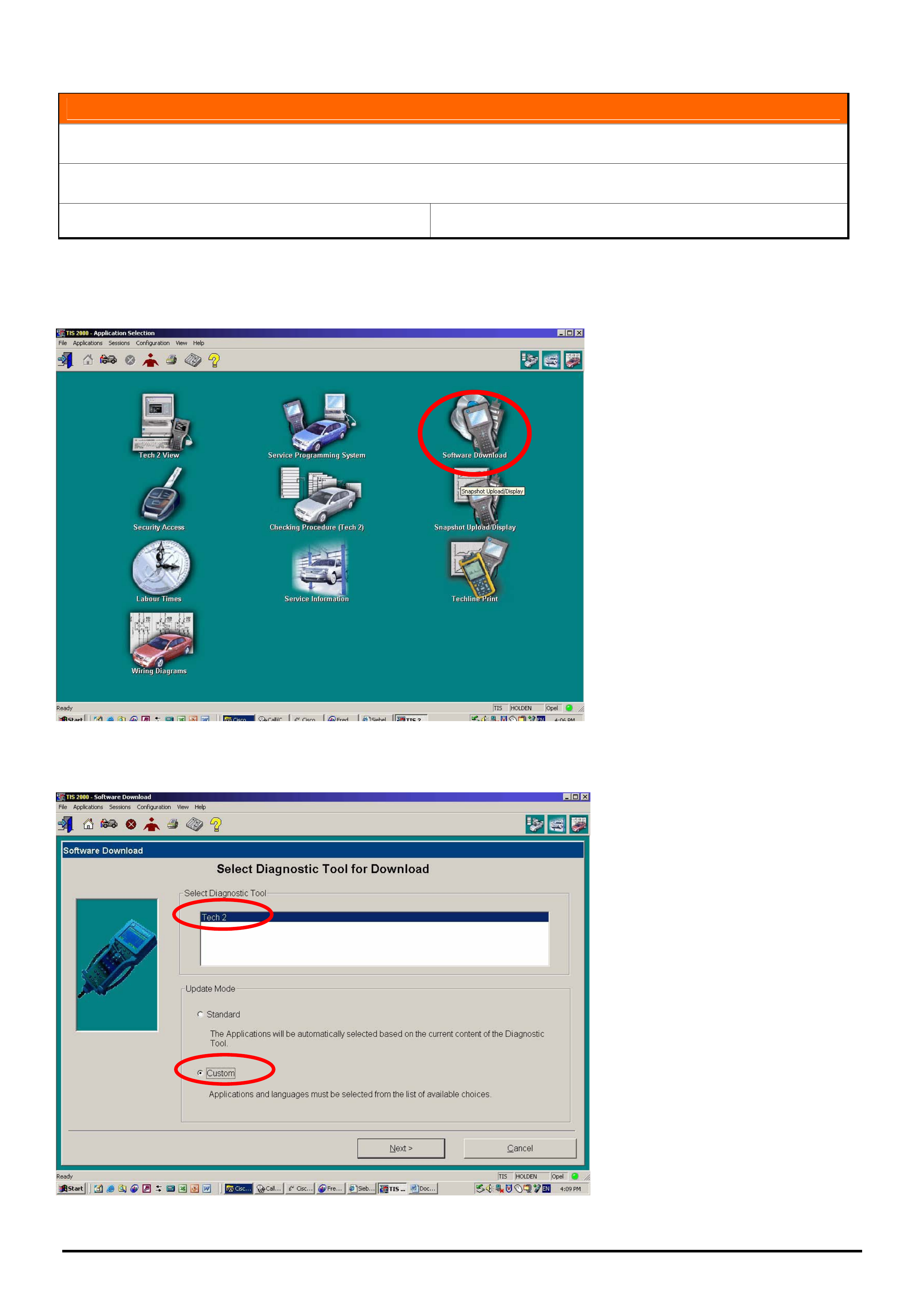
HOLDEN SERVICE TECHLINE ___________________________________________________________________________OCTOBER, 2005
11
Holden Techlines are written to inform technicians of conditions that may occur on some vehicles, and to provide information that could assist in the
proper service fix of a vehicle. If a condition is described, do not assume the service fix applies to a vehicle or that the vehicle will have that condition.
INFORMATION
Tech 2 Custom Downloads
All
Group OB Ref. No. TL0999 - 0509
At times service departments may need to use TIS 2000 to change Tech 2 software to an earlier version.
The following instructions detail the correct procedure to do this.
1.From the TIS 2000 main menu select Software Download
2. Select “Tech 2” from the upper menu and “Custom” from the lower menu.
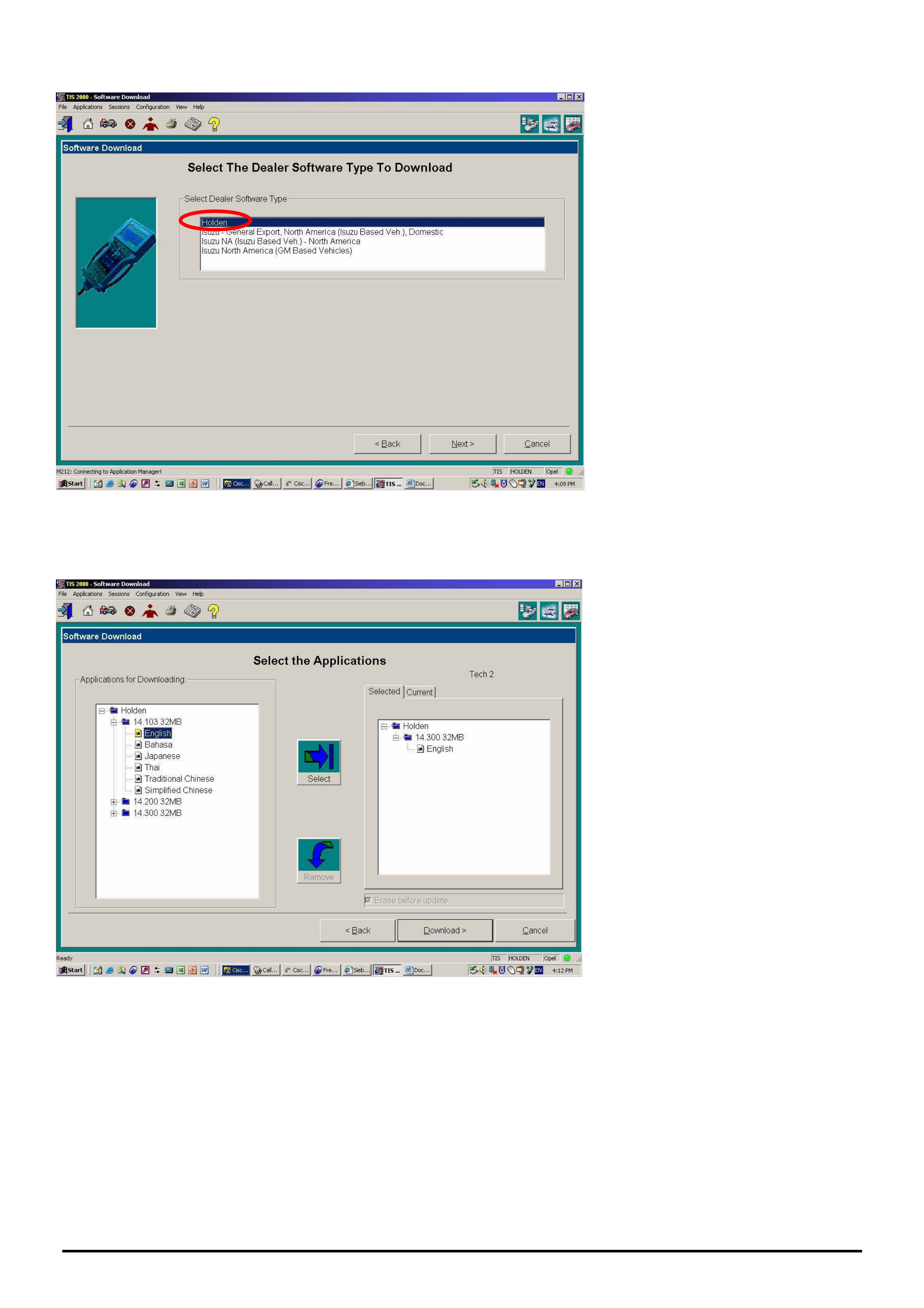
HOLDEN SERVICE TECHLINE ___________________________________________________________________________OCTOBER, 2005
12
Holden Techlines are written to inform technicians of conditions that may occur on some vehicles, and to provide information that could assist in the
proper service fix of a vehicle. If a condition is described, do not assume the service fix applies to a vehicle or that the vehicle will have that condition.
3. Select Holden
When presented with the above screen, from the Applications for Downloading area, select the version and language
you wish to download. Once highlighted, press the Select button. The detail of what will be downloaded will now
appear on the right of the screen. If the details are correct Select download.
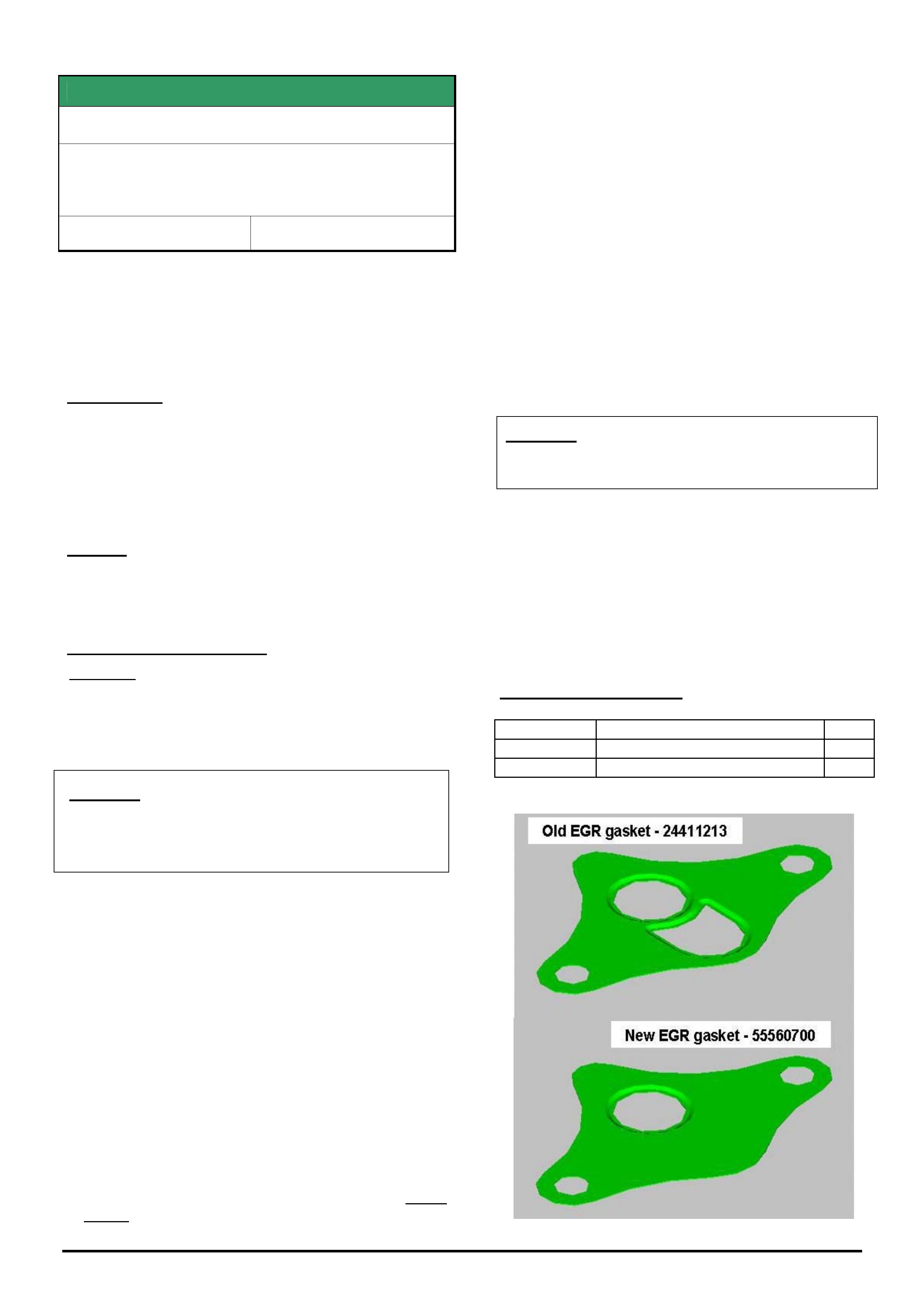
HOLDEN SERVICE TECHLINE ___________________________________________________________________________OCTOBER, 2005
15
Holden Techlines are written to inform technicians of conditions that may occur on some vehicles, and to provide information that could assist in the
proper service fix of a vehicle. If a condition is described, do not assume the service fix applies to a vehicle or that the vehicle will have that condition.
SERVICE FIX
EGR Malfunction, DTC P0400 Sets
XC Combo (Z16SE engine)
Model Years 2003 and 2004 Only
Group 6C Ref. No. TL0941B - 0509
This Techline supercedes TL0941A-0508 published in
Issue 8, Sep. 2005. The procedure is updated with advice
to not replace the EGR valve. Either fit a revised gasket or
discard valve and fit a blanking plate. Also, TIS CD 64 now
allows MY 2003 vehicles to be repaired with this service
fix.
-----------------------------------------------------------------
CONDITION
Drivers may complain of: - engine running ‘rough’
and/or may, in isolated cases, stall at very low speeds
during this ‘rough running’ period, and engine check
lamp illuminates.
Technicians may find DTC P0400 set.
CAUSE
Deposits of contaminants built up between the EGR
pintle and its guide causing the pintle to seize.
CORRECTION in Service
Summary: On complaint vehicles ensure EGR valve
is fully closed before disabling its operation with
revised engine management software. If EGR valve
is not fully closed, remove and refit valve using
revised gasket that has EGR port blocked off.
CAUTION: The following service fix action must
not be applied to Model Year 2002 vehicles. On
these vehicles address EGR complaints only by
fitting a new EGR valve.
On any Model Year 2003 or 2004 vehicle with the
condition as described above, proceed as follows.
Step 1. - Check position of the EGR Valve.
The position of the EGR valve can be found by
performing the 'Actuator test' with TECH 2, selected
as follows:
Diagnostics,
Model Year,
Vehicle Type,
Engine,
Actuator test,
EGR Solenoid test,
EGR position Feedback.
(1a). If the EGR position feedback is between
0.15V and 1.5V after performing the test (Test
Status: Inactive) the EGR valve is closed - Go to
Step 2.
(1b). If the EGR position feedback is higher than
1.5V after performing the actuator test (Test Status:
Inactive) the EGR valve is not completely closed. In
this case, install gasket p/n 55560700 which has
EGR port blanked out. Refer Figure 1. Tightening
torque of attaching bolts is 20Nm.
NOTE: If gasket 55560700 is unavailable, remove
EGR valve completely and install a blanking plate
12554606 with the old gasket 24411213.
Step 2. - Reprogram ECU.
Reprogram the ECU with modified software,
available from TIS CD 64 and onward, which
deactivates the EGR function. The correct hardware
number and revised ECU software part numbers are
listed in the table on the next page.
CAUTION: TIS2000 CD numbers prior to 64 must
not be used for reprogramming on Model Year
2003 vehicles.
Step 3. - Vehicle Marking
All vehicles that are modified according to the above
information are required to be clearly marked by a
yellow paint dot on the upper side of the EGR valve
housing. This will alert service technicians that the
engine management system has been revised and
the EGR is disabled.
PARTS INFORMATION
Part No.: Part Name Qty:
55560700 Gasket – EGR (Revised type) 1
12554606 Blanking Plate (EGR) 1
HOLDEN SERVICE TECHLINE ___________________________________________________________________________OCTOBER, 2005
16
Holden Techlines are written to inform technicians of conditions that may occur on some vehicles, and to provide information that could assist in the
proper service fix of a vehicle. If a condition is described, do not assume the service fix applies to a vehicle or that the vehicle will have that condition.
WARRANTY CLAIM INFORMATION
Description Deactivate EGR valve
Labour Op. No. J000788
Time 0.2 hours
Add 0.2 hr if fitting revised
EGR gasket
Failure Code N0012 foreign material
HARDWARE & SOFTWARE PART NUMBERS
XC Combo Model Year 2003
ECU - Hardware Number
DEL 0115351289
ECU - Service Part
Number
09391340
EGR Disable ECU
Software Part Number
12 214 840.8
Available as of TIS CD 64
XC Combo Model Year 2004
ECU - Hardware Number
DEL 0115214590
ECU - Service Part
Number
12214810
EGR Disable ECU
Software Part Number
12 237 460.6
Available as of TIS CD 61
INFORMATION
Removal and Reinstallation Of Front Brake
Hose On Vehicles In The Range L384762 –
L452327
VZ except AWD, WL
Group 5 Ref. No. TL0996 - 0509
Vehicles built in the range from L384762 to L452327
were fitted with a rivet in the front strut brake hose
attaching bracket to prevent the hose slipping from the
strut bracket. Vehicles built after L452327 (27/5/05)
were fitted with a restraining clip 92183627 instead of
the rivet.
If any vehicle in the range from L384762 to L452327,
requires normal removal of the front brake hose from
the strut, the rivet as mentioned above, will need to be
removed. Use a 3.2mm drill bit to drill out the rivet.
WHEN REINSTALLING THE BRAKE HOSE AND
ABS CABLE, A CLIP PART NUMBER 92183627
MUST BE INSTALLED TO RETAIN THE BRAKE
HOSE.
The procedure for installing the clip is shown on the
next page.
NOTE: Safety Recall Campaign number 05-H-04,
required the clip 92183627 to be fitted to all vehicles
(VZ except AWD and WL) built prior to L384762.
PARTS INFORMATION
Part No.: Partfinder Name Qty:
92183627 Clip retainer – front brake 1
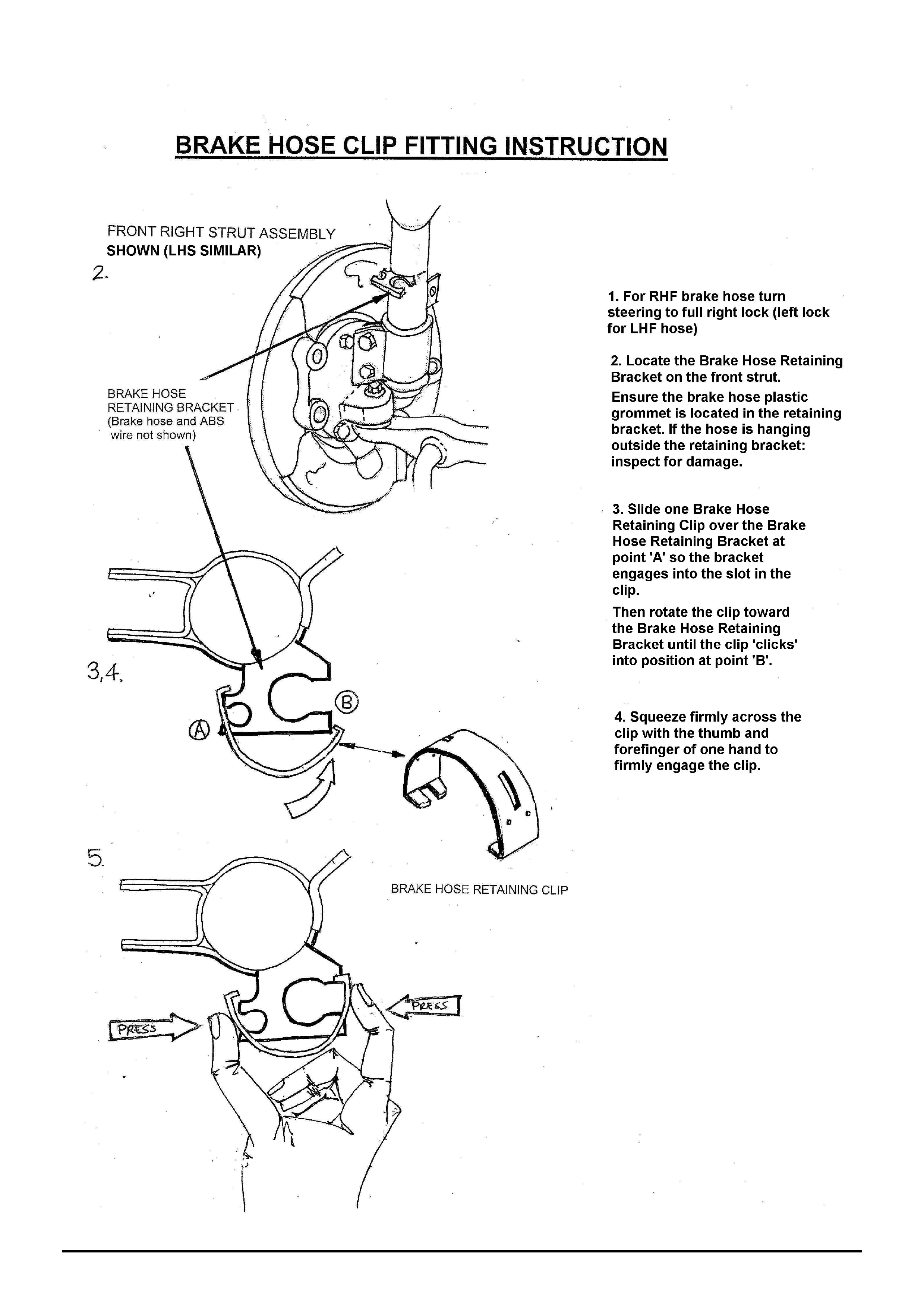
HOLDEN SERVICE TECHLINE ___________________________________________________________________________OCTOBER, 2005
17
Holden Techlines are written to inform technicians of conditions that may occur on some vehicles, and to provide information that could assist in the
proper service fix of a vehicle. If a condition is described, do not assume the service fix applies to a vehicle or that the vehicle will have that condition.
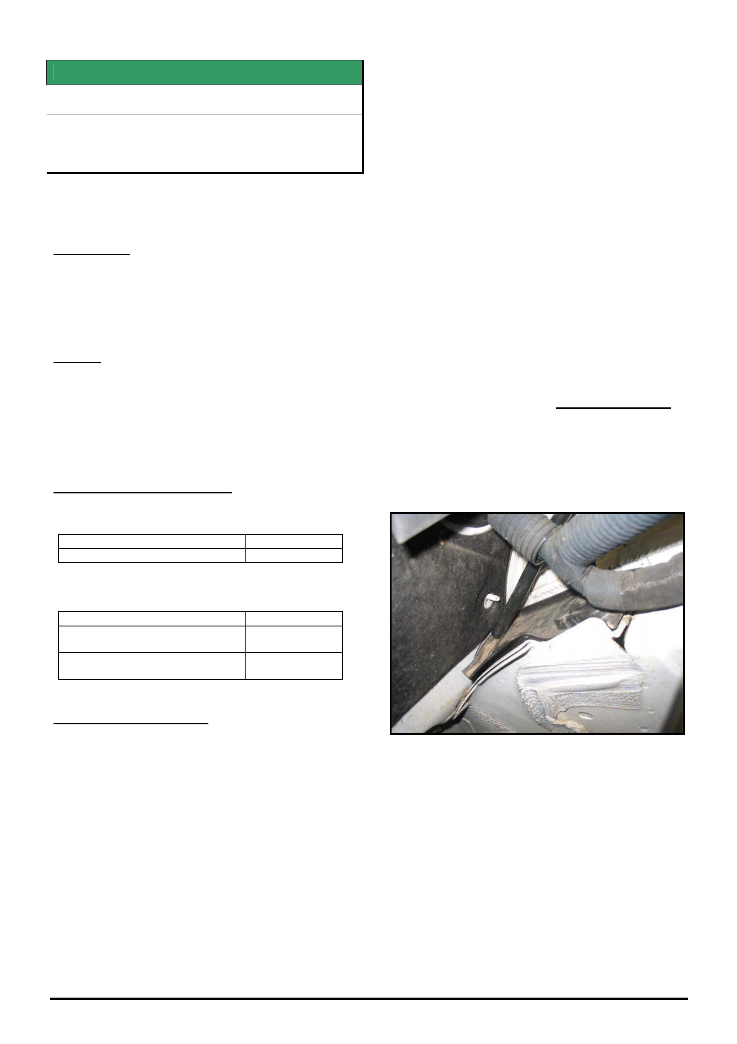
HOLDEN SERVICE TECHLINE ___________________________________________________________________________OCTOBER, 2005
18
Holden Techlines are written to inform technicians of conditions that may occur on some vehicles, and to provide information that could assist in the
proper service fix of a vehicle. If a condition is described, do not assume the service fix applies to a vehicle or that the vehicle will have that condition.
SERVICE FIX
DTC’s P0700, P0715, P0720
ZC with A/T
Group 7B Ref. No. TL0737B - 0509
This Techline supercedes TL0737A-0508 published in
Issue 8, Sep. 2005. It is updated by revising steps 5 and
6 of the procedure.
---------------------------------------------------------------------
CONDITION
Customer may complain of “no shifting” or “incorrect
shifting” of transmission ratios.
One or all of the following DTC’s may be stored:
P0700, P0715 or P0720
CAUSE
There are 2 possible causes for the above condition.
1. Moisture may have entered the speed sensor
connector, causing an incorrect or interrupted
signal.
2. Coolant may have entered the transmission via the
radiator oil cooler
CORRECTION – Production
1. Protective grease applied to speed sensors
from:
Trans. Serial No.: Built Date:
03MV735125 06/01/04
2. Radiators with revised oil cooler sealing were
introduced into vehicle production from:
ISOVIN: Built Date:
Ellesmere Port:
W0L0ZCF6848035197
not available
Russelsheim
W0L0ZCF3541042598
not available
CORRECTION – Service
1. Disconnect the speed sensor connector and dry
out any moisture present.
2. If there is no evidence of corrosion or damage to
terminals apply grease p/n 09163339 to connector
to stop future moisture entry.
3. If corrosion or damage is evident, replace the
sensor and/or connector as required. Also apply
grease 09163339 to connector to stop future
moisture entry.
4. Remove transmission valve body cover
CAREFULLY and inspect for possible coolant
entry to transmission via the radiator oil cooler. If
there is no evidence of moisture contamination, no
further action is required If there is evidence of
moisture contamination, proceed to step 5. .
5. If vehicle ISOVIN is prior to those shown in the
Production Correction table, replace the radiator,
then proceed to step 6.
If vehicle ISOVIN is after those shown, pressure
check radiator. If radiator fails pressure test,
replace radiator then go to step 6. If radiator
passes pressure test, proceed to step 6.
6. Refit transmission valve body cover and flush the
transmission to remove traces of water/coolant
contamination. The transmission can be flushed
using a commercial flushing unit or as follows.
Disconnect the transmission to radiator oil cooler
line and drain into a suitable container. With
engine idling and A/T in Neutral, flush approx 10 to
12 litres of standard Dexron A/T fluid through the
transmission.
After flushing, reconnect cooler line and refill
transmission with the specified A/T fluid as
shown in Parts Information.
7. Check the routing of the transmission breather
hose. The breather hose outlet MUST NOT be
located in the plastic gutter that drains A/C
condensate. Refer Figure 1.
Figure1 – Shows breather hose incorrectly located.
8. Relocate the breather hose so that it is clear of the
drain channel. Refer Figure 2. Secure hose to
conduit with tie straps as required.
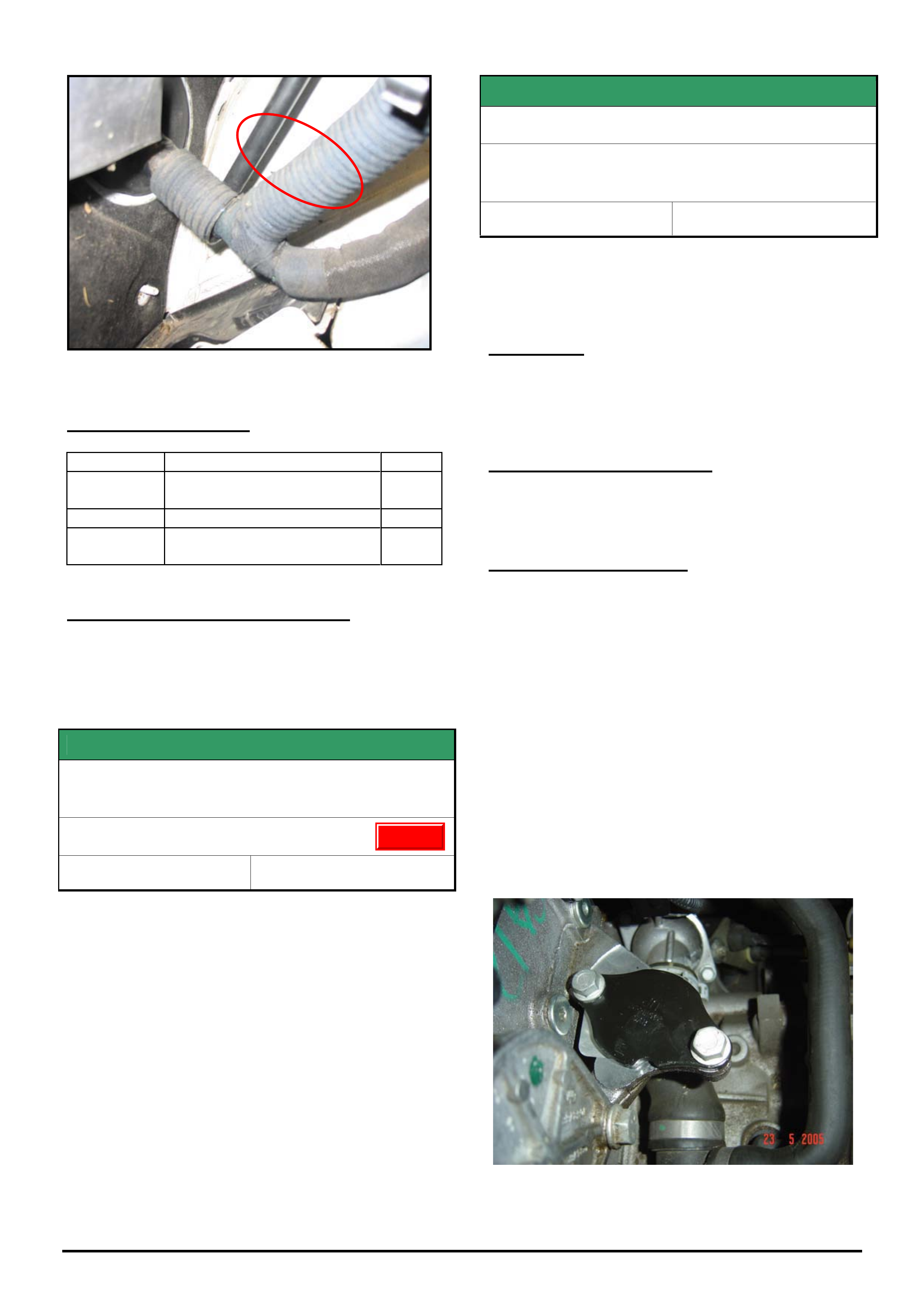
HOLDEN SERVICE TECHLINE ___________________________________________________________________________OCTOBER, 2005
19
Holden Techlines are written to inform technicians of conditions that may occur on some vehicles, and to provide information that could assist in the
proper service fix of a vehicle. If a condition is described, do not assume the service fix applies to a vehicle or that the vehicle will have that condition.
Figure 2. Shows relocated A/T breather hose.
PARTS INFORMATION
Part No. Description Qty
09163339 Grease. NYOGEL 760G -
25 gm tube
1
93173888 speed sensor 1
93160393 Automatic transmission oil
1 litre (Esso ATF 3309)
WARRANTY CLAIM INFORMATION
Refer to your District Aftersales Manager.
SERVICE FIX
TPMS Module Unable To Detect One Or Both
Front Tyre Pressures & Sets DTC 9 or 10
WL Caprice, HSV Grange
Group 12 Ref. No. TL0970A - 0509
This Techline supercedes the previous one, TL0970 -
0507, in Issue 7 Aug. 2005. It is updated with advice to
fit the latest module 92183577 if not already fitted.
Please add this information to your original copy of the
techline.
Refer to the Holden portal website “Lionheart” for the
full revised techline.
SERVICE FIX
EGR Malfunction
ZC Vectra, TS Astra, TT Zafira,
- all with Z22SE engine
Group 6C Ref. No. TL0919A - 0509
This Techline supercedes TL0919-0505 in Issue 5, June,
2005. It is updated by removing the EGR Valve from the
Parts Information as it is not required. TS and TT have
also been added to the models affected .
CONDITION
Driver may report that vehicle runs rough or lacks
power and the telltale light comes on.
Technician finds DTC P1404 is set (EGR valve stuck).
CORRECTION – Production
The EGR-valve was removed in production (during
Model Year 2004) from Engine No. Z22SE11293531
CORRECTION – Service
On complaint vehicles where diagnosis finds that an
EGR valve is faulty, it should not be renewed but
removed altogether as per the following procedure.
Procedure.
1. Close exhaust gas recirculation port with a cover
plate (Part No. 24575592). Replace gasket when doing
so. (Part No. 12570863). The groove on the plate has
to point in the direction of the radiator with the plate
labelling facing upwards.
2. Fix the redundant wiring harness connector with a
cable strap (face connector opening to rear of vehicle).
3. Program ECU with SPS as of TIS 2000, CD 56 and
onward (select without EGR).
Figure 1. Shows EGR cover plate with groove facing
towards front of vehicle.
Update
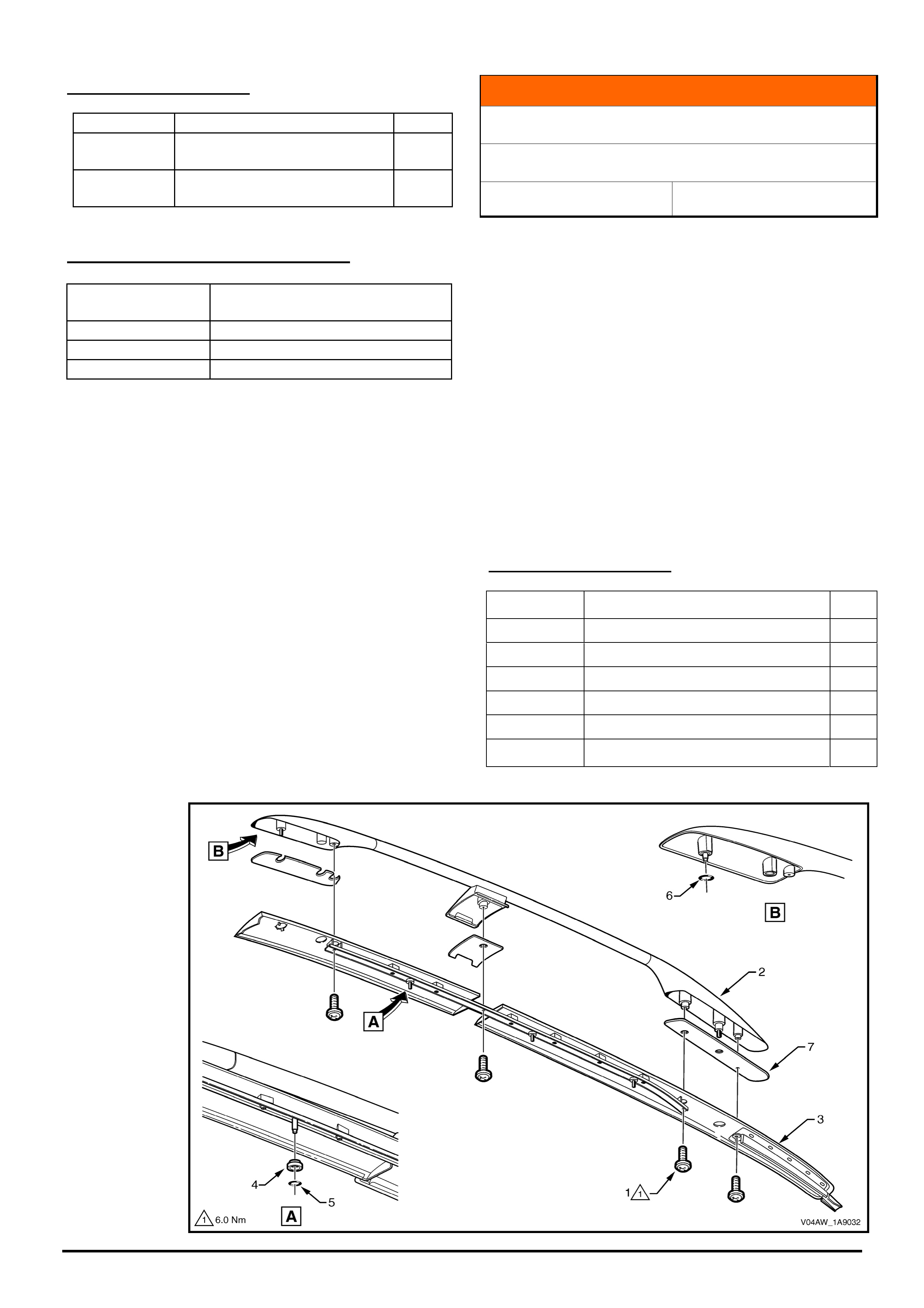
HOLDEN SERVICE TECHLINE ___________________________________________________________________________OCTOBER, 2005
20
Holden Techlines are written to inform technicians of conditions that may occur on some vehicles, and to provide information that could assist in the
proper service fix of a vehicle. If a condition is described, do not assume the service fix applies to a vehicle or that the vehicle will have that condition.
PARTS INFORMATION
Part No.: Partfinder Name Qty:
24575592 Cover plate- EGR valve
opening
1
12570863 Gasket - EGR valve to cyl
head
1
WARRANTY CLAIM INFORMATION
Description Remove EGR valve, add cover
plate, and reprogram ECU
Labour Op. No. J000776
Time 0.6 hr
Failure Code J0057 registers incorrectly
INFORMATION
Servicing Roof Rails
VY & VZ Adventra
Group 1 Ref. No. TL0884 – 0509
The roof rails and the front and rear plastic mouldings
are now available as individual replacement parts.
Previously, only the complete roof rail assemblies
could be purchased from spare parts.
From now on, if a roof rail is to be repaired under
warranty, only replace the individual component at
fault. DO NOT replace the complete roof rail assembly.
For instructions on DISASSEMBLY and
REASSEMBLY refer to PV SIP by selecting the
following path:
VY / Service Information / MY2004 VY AWD Wagon /
External Fittings / Section 1A9 / 2 Service Operations /
2.7 Roof rack carrier Asm
PARTS INFORMATION
Part No.: Partfinder Name Qty
92116853 (RH) Carrier - luggage 1
92116849 (RH) moulding - luggage carrier front 1
92116851 (RH) moulding - luggage carrier rear 1
92116852 (LH) Carrier - luggage 1
92116848 (LH) moulding - luggage carrier front 1
92116850 (LH) Moulding - luggage carrier rear 1

HOLDEN SERVICE TECHLINES___________________________________________________________________________NOVEMBER, 2005
6
Holden Techlines are written to inform technicians of conditions that may occur on some vehicles, and to provide information that could assist in the
proper service fix of a vehicle. If a condition is described, do not assume the service fix applies to a vehicle or that the vehicle will have that condition.
INFORMATION
Introduction Of DVD for TIS 2000 in Jan. 2006
All
Group OB Ref. No. TL1025 - 0510
From January 2006 the previous CD-ROMs for TIS
2000 will be replaced by a DVD.
The major growth in data in recent years makes this
change necessary.
Advantages to the user:
• the previous data set of 4 CDs will be replaced by
one DVD
• simpler updates, without having to change the CD
several times
• updates as a whole will be produced more quickly
• improved quality graphics
• use of new illustrations is possible, e.g. digital
photos
• conventional CD-ROMs can also be read by DVD
drives
Please ensure that your TIS 2000 PC has a DVD drive
by 1/1/2006 at the latest.
This subject was covered in All Holden Dealer Letter
DL 25/05 .
INFORMATION
Immobiliser Security Code Requests via
NOW
JS VECTRA
GROUP OB TL1021-0510
It is possible when searching for Immobiliser security
codes on the NOW system for JS Vectra, that it will
display the Immobiliser Code as a BCM code.
Although JS Vectra does not have a BCM, the NOW
system uses this menu field to display the immobiliser
security code.
INFORMATION
Bluetooth Phone Kit
VZ SSZ Sedan, HSPO Accessory
(GROUP OB) TL1024-0510
Holden now offers the Bluetooth Mobile Phone kit
through HBD and HSPO, and also as a standard feature
on the VZ SS-Z Sedan.
Customers should be made aware that mobile phones
with Bluetooth capability are not necessarily compatible
with the Holden Bluetooth mobile phone kit.
Dealers should refer to the ‘Bluetooth Compatibility’
document for the most up-to-date listing of tested mobile
phones. This document is available for download from
the Holden Dealer Web Centre,
www.holden.com.au/dwc. Go to the ‘HBD & Genuine
Accessories’ section and look in the ‘Bluetooth’ folder.
If you do not have the password to access the Dealer
Web Centre, speak to someone in your sales
department.
Mobile phones listed as ‘Not yet tested’ have not yet
been tested by the supplier, so we are unable to
comment of the compatibility of these phones with the
Holden Bluetooth phone kit until testing is complete.
INFORMATION
Radio Security Code Requests
XC, AH, ZC with CDC30 and CDC40 audio
head units
GROUP OB TL1020-0510
This is a reminder to the dealers who send Radio
Security Code Requests through to the vehicle security
information centre.
When requesting radio PIN codes for XC, AH and ZC
fitted with Blaupunkt CDC30 or CDC40 audio head
units, be aware that the Vehicle Security Code is also
the radio security code.
Update

HOLDEN SERVICE TECHLINES___________________________________________________________________________NOVEMBER, 2005
7
Holden Techlines are written to inform technicians of conditions that may occur on some vehicles, and to provide information that could assist in the
proper service fix of a vehicle. If a condition is described, do not assume the service fix applies to a vehicle or that the vehicle will have that condition.
INFORMATION
Front Wheel Camber Spec. Correction
VY/VZ - All AWD
Group 3 Ref. No. TL1031 - 0510
This bulletin is to advise of a correction to the camber
specification on all AWD vehicles.
FRONT WHEEL ALIGNMENT AT CURB WEIGHT
Wheel Alignment Angle Specifications - All
Models
Camber – 0° 12' ± 0° 18’
Caster 8° 30' ± 1° 15'
Toe-in Degrees Total 0° 10’ ± 0° 10'
Degrees per Wheel +0° 5’ to +0° 5’
Toe-out on Turns 1° 42’ @ 20 ° turn angle
± 1° 30'
Steering Axis Inclination
Angle
13° 18’ ± 1° 30'
Included Angle 13° 06’ ± 1° 30'
This revised information will be included in the next
issue of SIP CD.
Please ensure all service personnel involved in
alignment work are advised of this correction.
DIAGNOSIS HINT
V6 Poor Performance On Vehicles fitted with
LPG
V & W series
Group 6C Ref. No. TL1018 - 0510
CONDITION
When investigating customer complaints of poor
engine performance on either Petrol or LPG the
following diagnosis is suggested.
SUGGESTED DIAGNOSIS
First of all, confirm that there are no DTC’s or other
obvious faults that may impact engine performance.
Next, remove the rocker covers and check the valve
guides for excessive wear. Excessive valve guide
wear can generate valve train noise which is
transmitted to the engine block. The knock sensor may
then detect this noise as engine detonation and thus
retard the spark timing. The result is reduced engine
performance.
If excessive wear is found in the valve guides refer to
SIP or work shop manual for appropriate repair
procedure.
DIAGNOSIS HINT
Fault lights Appear in Instruments
Dealer Cannot Reproduce Fault
All Models & All Electronic Systems
Group 12 Ref. No. TL1019 - 0510
CONDITION
Customer reports that fault lights intermittently appear
in instrument cluster, such as ABS/Trac, Airbag, Check
Engine Light, etc.
After checking the related electronic system with Tech
2 there may be ‘History’ DTC’s that have been set.
After following the diagnostics related to that system
no fault can be found.
POSSIBLE CAUSE
After questioning the customer you may find that the
fault light(s) only appear immediately after start, or
during cranking, and not while driving.
A possible cause is low voltage during cranking due to
poor battery condition or battery connections.
If electrical faults and/or DTC’s occur during engine
cranking, by the time the customer has driven the
vehicle to the dealership, there may be enough surface
charge in the battery to cause a “No Fault Found”
scenario.
Dealerships should check the condition of the battery
by conducting a battery load test to remove any
possible surface charge.
The above scenario highlights the necessity to follow
strategy based diagnostics. For more information on
Strategy Based Diagnostics, refer to All Dealer Letter
DL 12/05 which can be found on Lionheart or in PV
SIP.
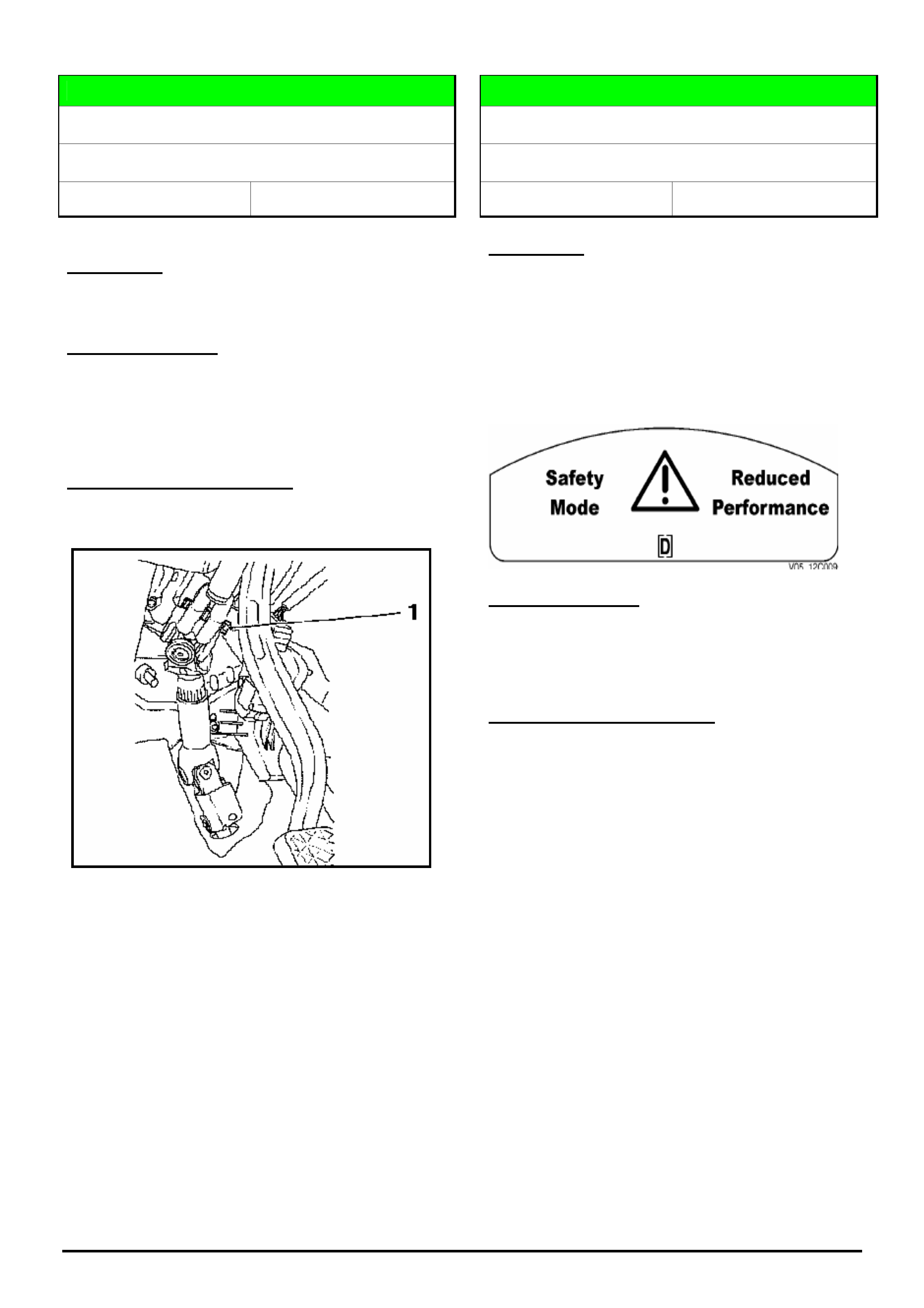
HOLDEN SERVICE TECHLINES___________________________________________________________________________NOVEMBER, 2005
8
Holden Techlines are written to inform technicians of conditions that may occur on some vehicles, and to provide information that could assist in the
proper service fix of a vehicle. If a condition is described, do not assume the service fix applies to a vehicle or that the vehicle will have that condition.
DIAGNOSIS HINT
Steering Column Knocking Noise.
XC Barina & Combo
Group 9 Ref. No. TL1017 - 0510
CONDITION
Knocking noise in the area of steering column.
POSSIBLE CAUSE
The tightening torque of the upper screw of the
steering intermediate shaft may be too low.
Refer item 1 in following picture.
SUGGESTED CORRECTION
Check screw for tightening torque as specified in TIS.
Replace screw if required as per TIS procedure.
DIAGNOSIS HINT
Engine Cranks But Will Not Start Intermittently
VZ, WL, 190 & 175 kw V6 engine
Group 12 Ref. No. TL1014 - 0510
CONDITION
Intermittently, engine will crank for 5 seconds but will
not start and run. On a DTC search the following low
voltage codes may have been set. P0560 P0458
P0693 P0691 P0628 P0646 P0276 P00273 P0270
P0267 P0264 P0261 P2092 and P2088.
Vehicle may also display the message below in the
instrument cluster.
POSSIBLE CAUSE
There may be an intermittent loss of power to the
engine control relay circuit for the injectors and engine
sensors.
SUGGESTED CORRECTION
On a vehicle with the symptoms described above,
check the engine control relay circuit for loose wiring
connectors etc. or a possible faulty relay.
Please submit PIRs on any vehicle seen with this
condition. Include rectification if applicable.
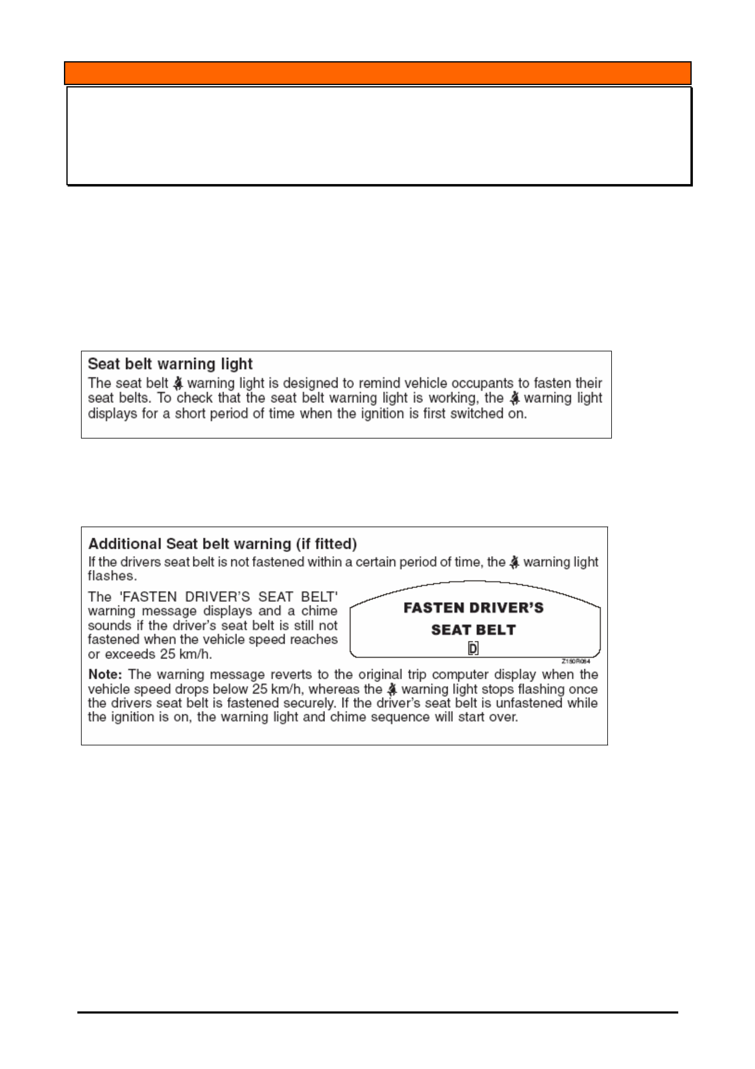
HOLDEN SERVICE
TECHLINES___________________________________________________________________________NOVEMBER, 2005
11
Holden Techlines are written to inform technicians of conditions that may occur on some vehicles, and to provide information that could
assist in the proper service fix of a vehicle. If a condition is described, do not assume the service fix applies to a vehicle or that the vehicle
will have that condition.
INFORMATION
Seat Belt Warning Operation
VY, VZ, Ute & Cab Chassis (One Tonner)
(GROUP 12) TL1022-0510
This techline is written to highlight the differences in the seat belt warning on VY & VZ Ute & Cab Chassis 2
door vehicles (One Tonner) versus the seat belt warning on Sedan, Wagon, Monaro and Crewman.
The differences are highlighted in the following information which is a direct copy of the latest owners
handbook in vehicle production from Sep/Oct 05.
The following warning is applicable to all models.
The following warning is applicable to Sedan, Wagon and Crewman models only.
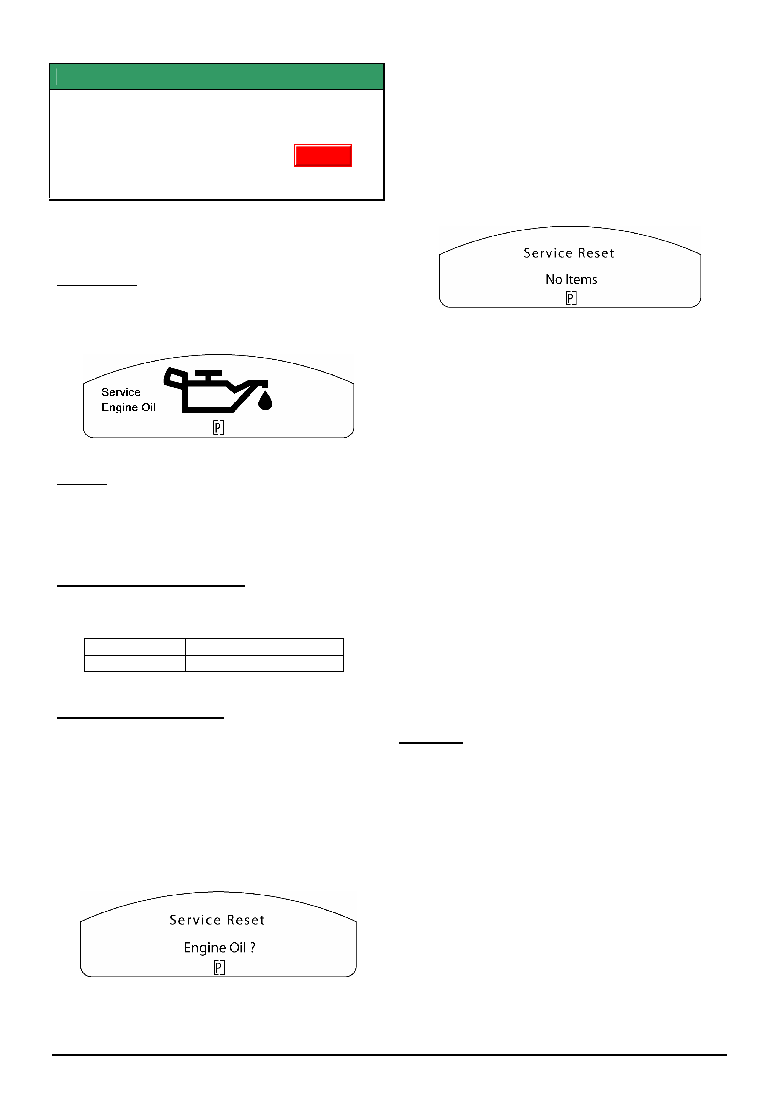
HOLDEN SERVICE TECHLINES___________________________________________________________________________NOVEMBER, 2005
12
Holden Techlines are written to inform technicians of conditions that may occur on some vehicles, and to provide information that could assist in the
proper service fix of a vehicle. If a condition is described, do not assume the service fix applies to a vehicle or that the vehicle will have that condition.
SERVICE FIX
Service Engine Oil Warning Displays in the
Instrument Cluster.
VZ & WL with Gen III only
Group 12 Ref. No. TL0890A - 0510
This Techline supersedes TL0890-0503 in Issue 3, April
2005. It is UPDATED by adding new information for Service
Correction and Warranty Claims.
CONDITION
On some vehicles the “Service Engine Oil” warning icon
may display in the instrument cluster when the ignition
is cycled.
CAUSE
The “Service Engine Oil” feature which is not available
for the local market, has been inadvertently enabled in
the engine calibration.
CORRECTION – Production
Revised engine calibrations were introduced over a one
week period ending in the production breakpoint below.
Build Date: ISO VIN:
05/10/2005 6G1ZK14F96L516298
CORRECTION – Service
The following solution applies only to Gen III vehicles. The
solution for HFV6 and HSV Gen 4 will be advised in a future
techline.
If the above warning icon displays, the following reset
procedure must be performed.
1. Press and hold the up and down buttons on the trip
computer mode switch while turning the ignition key
on until a beep is heard, the following will be
displayed.
2. Press the set button on the trip computer mode
switch until a beep is heard (approx 8-10 seconds) to
reset the service item.
The display will then revert back to the start up
sequence.
If more than one service items are set, the next
service item will be displayed.
Press the set button on the trip computer mode
switch to reset the next service item if required.
3. The following will then be displayed.
4. Re-program the ECU or PCM (engine or
powertrain control module) as per the standard SPS
(Service Programming System) process using Tech 2
and TIS 2000 version 65 or later.
NOTE: For detailed instruction on this process refer
to Holden Lionheart portal, Service Techlines,
Section OD – TIS, “Reprogramming Procedure –
Instrument Cluster SPS”.
5. Re-program the Instrument cluster as per the
standard SPS (Service Programming System) process
using Tech 2 and TIS 2000 version 65 or later.
NOTE: For detailed instruction on this process refer
to Holden Lionheart portal, Service Techlines,
Section OD – TIS, “Reprogramming Procedure –
Engine ECU / PCM SPS”.
6. Re-program the Fuel Gauge Calibration in the
instrument cluster using Tech 2 software version
14.502 or later from TIS 2000 version 65 or later.
NOTE: For detailed instruction on this process refer
to Holden Lionheart portal, Service Techlines,
Section OD – TIS, “Reprogramming Procedure –
Instrument Cluster Fuel Gauge calibration”.
CAUTION:
Software downloaded from TIS 2000 CD 65 or later is
not compatible with old instrument cluster software,
old engine ECU / PCM software or old fuel gauge
calibration from earlier releases of TIS 2000.
Therefore these three files must be used as a set
whenever programming an engine control module,
instrument cluster or fuel gauge calibration.
For example,
- If you re-program the engine control module you must
re-program the instrument cluster and fuel gauge
calibration using software from TIS 2000 CD 65 or later.
- If you replace and re-program the instrument cluster
module you must re-program the engine control module
and fuel gauge calibration using software from TIS 2000
CD 65 or later.
Update
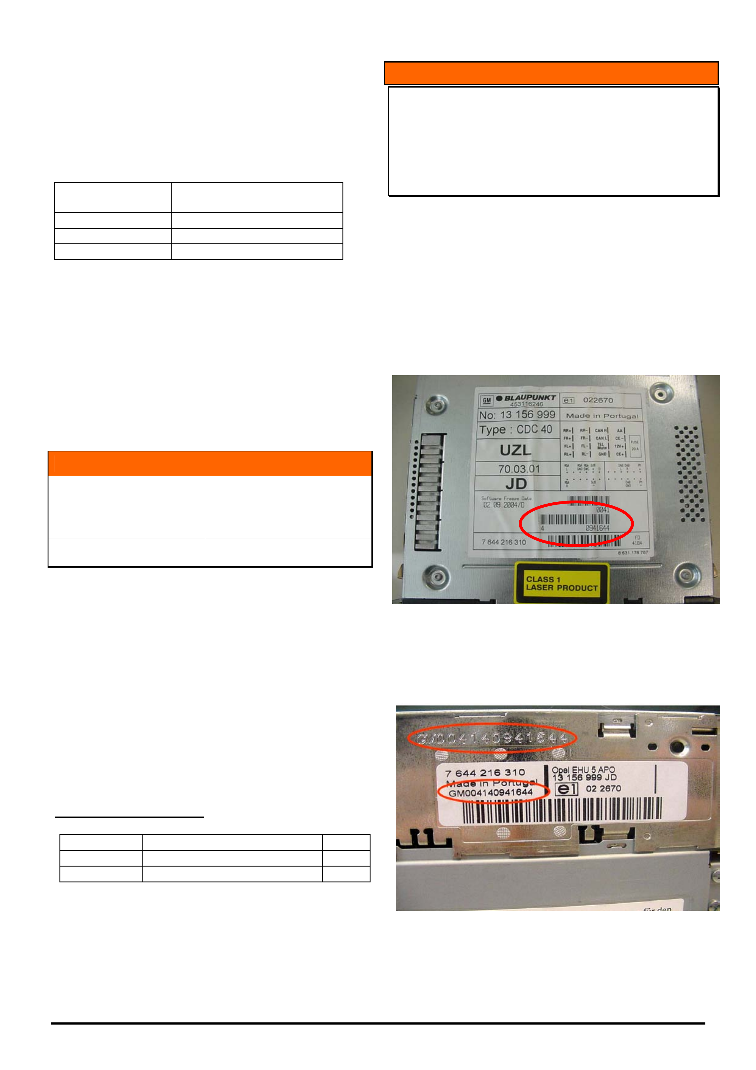
HOLDEN SERVICE TECHLINES___________________________________________________________________________NOVEMBER, 2005
13
Holden Techlines are written to inform technicians of conditions that may occur on some vehicles, and to provide information that could assist in the
proper service fix of a vehicle. If a condition is described, do not assume the service fix applies to a vehicle or that the vehicle will have that condition.
- If you re-program the fuel gauge calibration you must
re-program the engine control module and instrument
cluster using software from TIS 2000 CD 65 or later.
WARRANTY CLAIM INFORMATION
Description Service Engine Oil
Warning
Labour Op. No. J000791
Time V8 - 0.4 hrs
Failure Code J0057
NOTE: Labour operation number and time covers
instrument cluster, ECU / PCM and fuel gauge re-
programming.
INFORMATION
M/T Shift Fork Repair
V Car with Gen III V8 & M/T
Group 7A Ref. No. TL0925- 0510
Previously, when performing transmission repairs or
rebuilds, shift forks have had to be replaced merely
because the plastic pads attached to the forks have
been damaged and were not available as replacement
parts.
This is to advise that these shift fork plastic pads are
now available as separately serviced parts from HSPO.
In future, replace only the plastic pads unless other
physical damage has occurred to the shift fork to render
it unserviceable.
The pads are a push fit onto the fork ends.
PARTS INFORMATION
Part No.: Description Qty:
12523233 Pad - 5-6 & Rev. Shift Fork 2/fork
12523208 Pad - 1-2 & 3-4 Shift Fork 2/fork
INFORMATION
CDC 40 Opera Audio Unit Serial Number
Identification
ZC Vectra and AH Astra
(GROUP 12 ) TL0915A - 0510
This Techline supercedes TL0915-0504 in Issue 4, 2005. It is
updated by including the 3 groups of numbers on the bar
code in Figure 1 (was 2). Thanks to Adam Tipping of Hunter
Holden DC706 for reporting this on a PIR.
Whenever replacing a CDC 40 Opera radio via the
warranty changeover program it will be necessary to
obtain the serial number off the unit. The serial number
is located on the top of the unit (refer Figure 1) and on
the side (refer Figure 2.)
Figure 1. - Top View.
The serial number is a combination of “GM” plus the 3
groups of numbers on the bar codes as shown. In this
example the number is GM0041 4 0941644
Figure 2. - Side View
The serial number is stamped into the body of unit and
is also shown on the printed label.
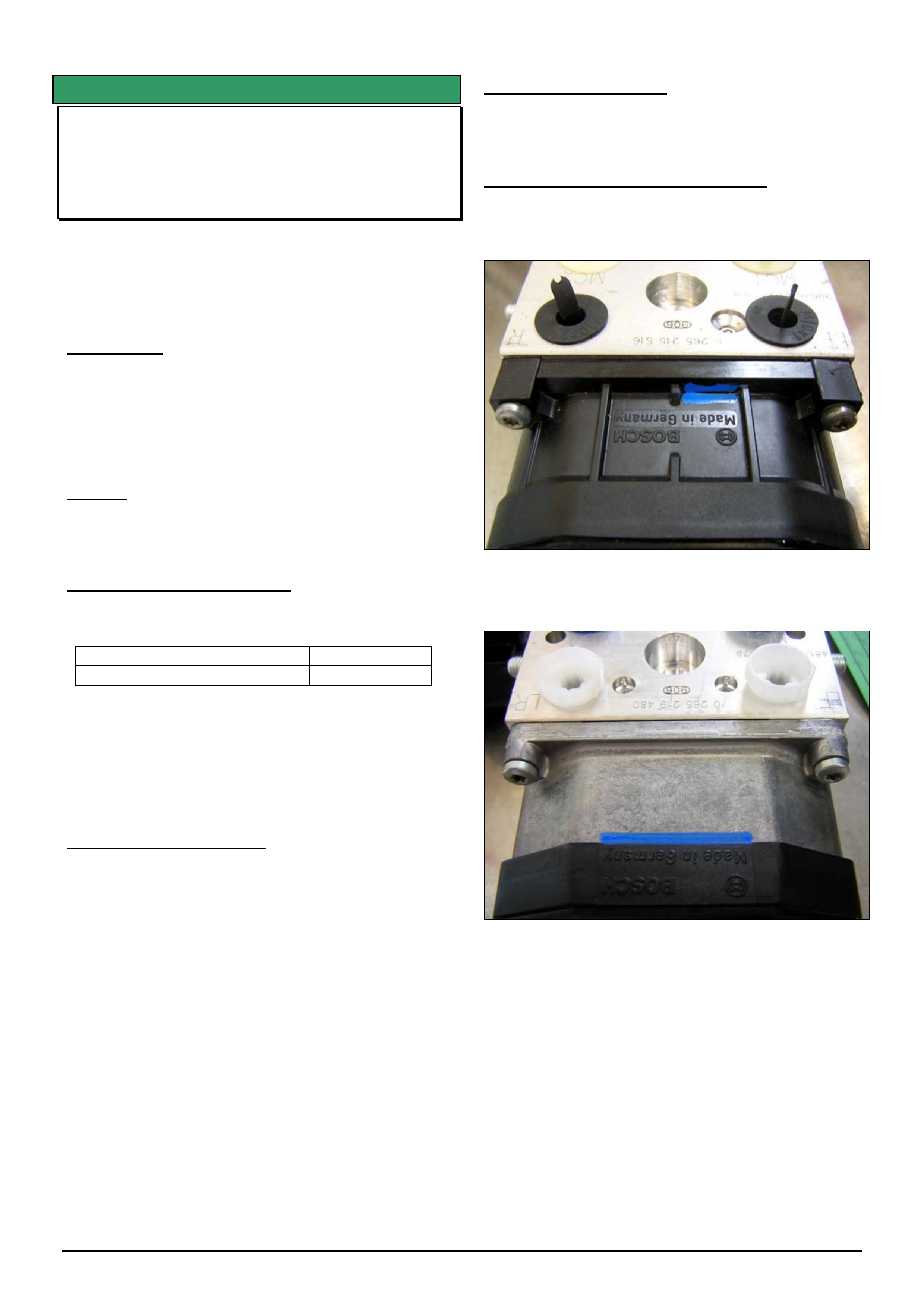
HOLDEN SERVICE TECHLINES___________________________________________________________________________NOVEMBER, 2005
14
Holden Techlines are written to inform technicians of conditions that may occur on some vehicles, and to provide information that could assist in the
proper service fix of a vehicle. If a condition is described, do not assume the service fix applies to a vehicle or that the vehicle will have that condition.
SERVICE FIX
ABS Light Comes On, DTC 71 Set
VY, V2, WK
(GROUP 5 ) TL0685A - 0510
This Techline supersedes TL0685-0404 in Issue 4, 2004. It is
updated with the current replacement guideline which is to
replace the Electronic Control Unit instead of the complete
hydraulic modulator / ECU assembly.
CONDITION
Customer reports the ABS Instrument panel light
comes on.
Dealer diagnosis reveals DTC 71 “Control Module
Internal Fault” is being logged. Diagnostic checks as
per SIP lead to module replacement.
CAUSE
An abnormality with the electronics in the ABS control
module which only occurs at vehicle start up.
CORRECTION – Production
Revised ABS electronic control modules have been
fitted to vehicles from:
ISOVIN: Built Date:
**********L239319 20/2/2004
NOTE: Revised modules fitted in production and
supplied from HSPO were originally identified with blue
paint as shown in the attached photographs. The blue
paint is no longer applied to replacement HSPO
replacement parts.
CORRECTION – Service
After verifying that vehicle has symptoms as described
above, fit a new ABS electronic control unit (ECU).
The ECU can be removed and replaced from the ABS
module.
The procedure for ECU replacement is in Passenger
Vehicle SIP.
Although the ECU is a relatively robust unit, technicians
still need to take care and follow correct procedures in
order to avoid ECU damage.
Service Prior Approval Process (SPAP) is required for
ECU replacement as per Special Warranty Component
Replacement Requirements in SIP.
PARTS INFORMATION
Refer to Microcat© for latest part numbers.
WARRANTY CLAIM INFORMATION
Use Labour Times information in Warranty Information
section of current PV SIP CD
Figure 1. P/N 92093868
Figure 2. P/N 92093870
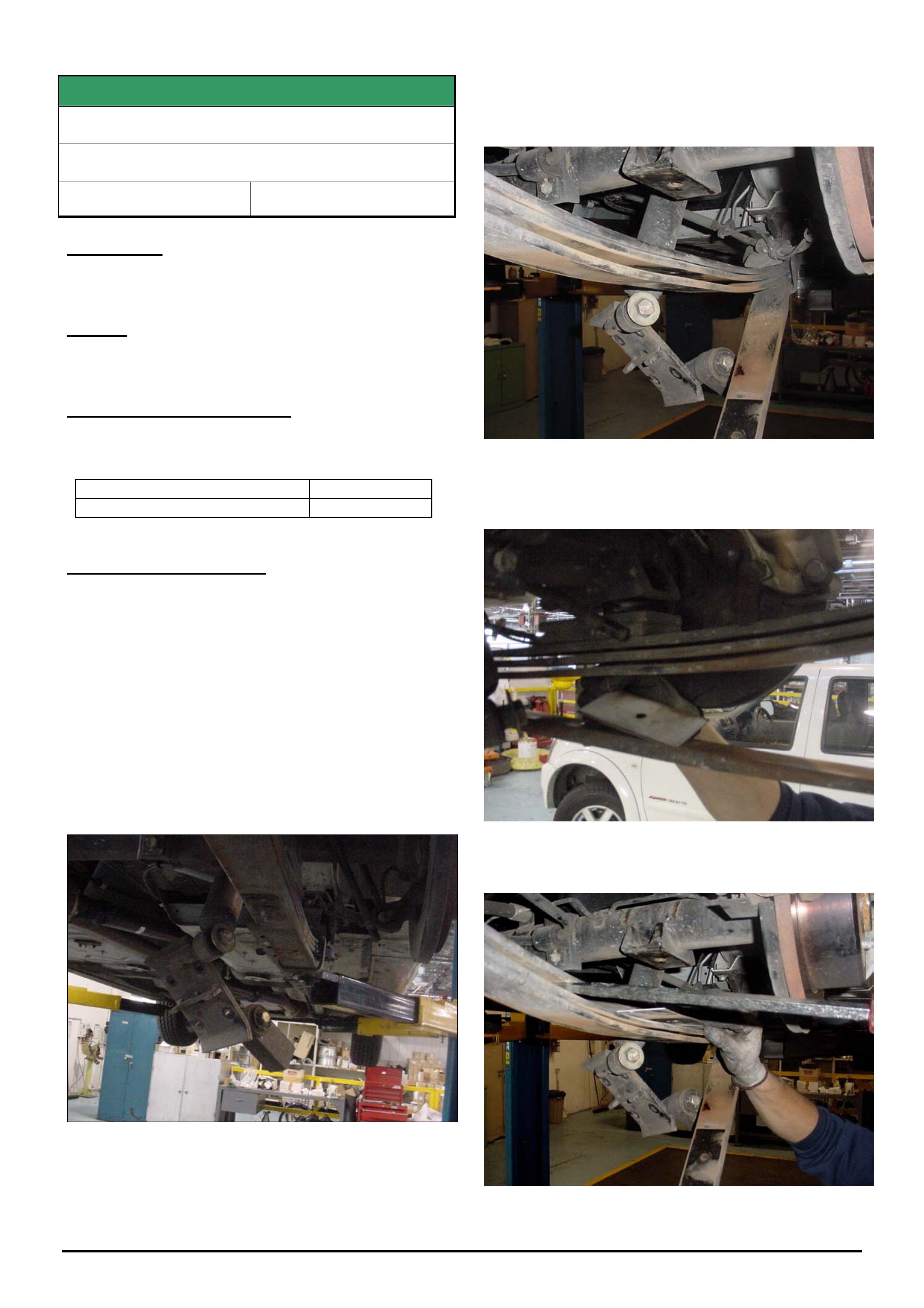
HOLDEN SERVICE TECHLINES___________________________________________________________________________NOVEMBER, 2005
15
Holden Techlines are written to inform technicians of conditions that may occur on some vehicles, and to provide information that could assist in the
proper service fix of a vehicle. If a condition is described, do not assume the service fix applies to a vehicle or that the vehicle will have that condition.
SERVICE FIX
Leaf Spring Squeaks
VY & VZ Crewman, Reg. Cab., Cross 8
Group 4 Ref. No. TL0855 - 0510
CONDITION
Squeak from leaf springs.
CAUSE
Contact between spring leaves.
CORRECTION – Production
Revised leaf spring assemblies with Delrin isolation
between each leaf have been fitted to vehicles from:
ISOVIN: Built Date:
**********L467474 4/7/2005
CORRECTION – Service
Summary: After verifying that the source of spring
squeak is inter leaf contact, install Delrin isolators
between each individual leaf in the spring pack as per
following procedure.
1. With vehicle on hoist, remove rear road wheels
to reduce weight as the differential will need to be
raised off the leaf springs.
2. Remove and discard the four U bolt retaining
nuts under leaf spring pack. Move bottom retaining
plate clear of leaf spring, letting it hang from the shock
absorber as shown in following figure.
3. Raise differential with a transmission jack so the
centre bolt can be removed.
4. Remove leaf spring centre-bolt nut carefully as
the bottom helper leaf will drop and only be supported
by the helper guide and hand brake cable bracket.
5. Remove and discard existing Delrin isolator that is
between helper leaf and 1st leaf . Refer following figure.
6. Insert the new Delrin isolators in between each
spring leaf (3 places).
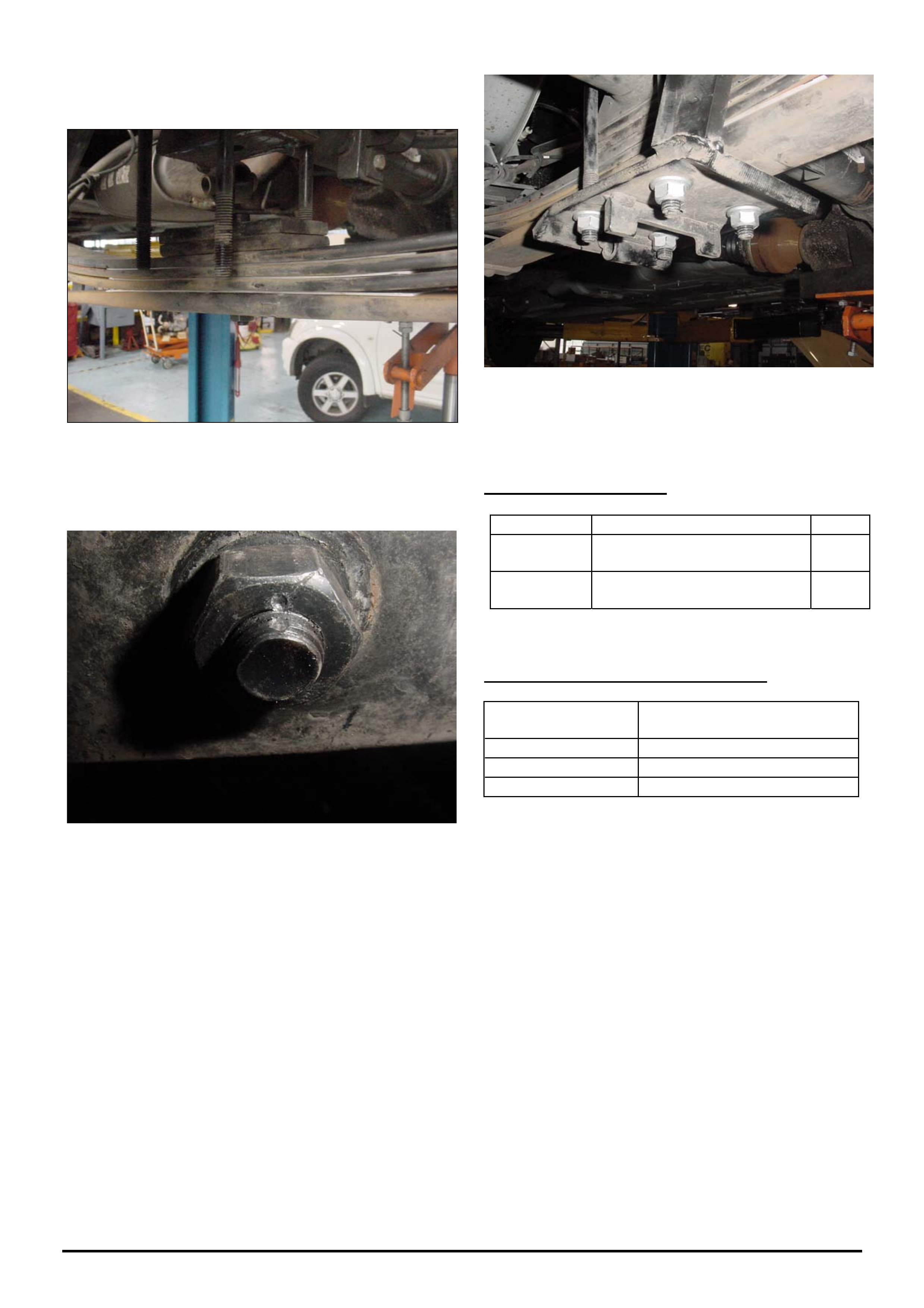
HOLDEN SERVICE TECHLINES___________________________________________________________________________NOVEMBER, 2005
16
Holden Techlines are written to inform technicians of conditions that may occur on some vehicles, and to provide information that could assist in the
proper service fix of a vehicle. If a condition is described, do not assume the service fix applies to a vehicle or that the vehicle will have that condition.
7. Install new centre bolt and torque nut to 49 – 61
Nm.
8. The centre bolt nut will need to be staked with a
centre punch at two opposing points on the nut face.
(Only 1 shown)
9. Lower the differential back into location.
10. Using the new U bolt nuts, bolt the bottom
retaining plate to the bottom of the spring pack. Ensure
that the nuts are tightened evenly to achieve an equal
number of threads protruding from the nuts. Torque to
90 Nm.
11. Ensure that the bottom helper spring guide is
centralised so it has clearance to the sides of the spring
leaves.
PARTS INFORMATION
Part No.: Partfinder Name Qty:
92185953 Kit – Crewman (Longer
Centre Bolt)
1
92185952 Kit - Reg. Cab (1 tonner) and
Cross 8
1
WARRANTY CLAIM INFORMATION
Description Leaf Spring Squeak Kit –
Install
Labour Op. No. F000203
Time 1.0 hr
Failure Code NOW F0090
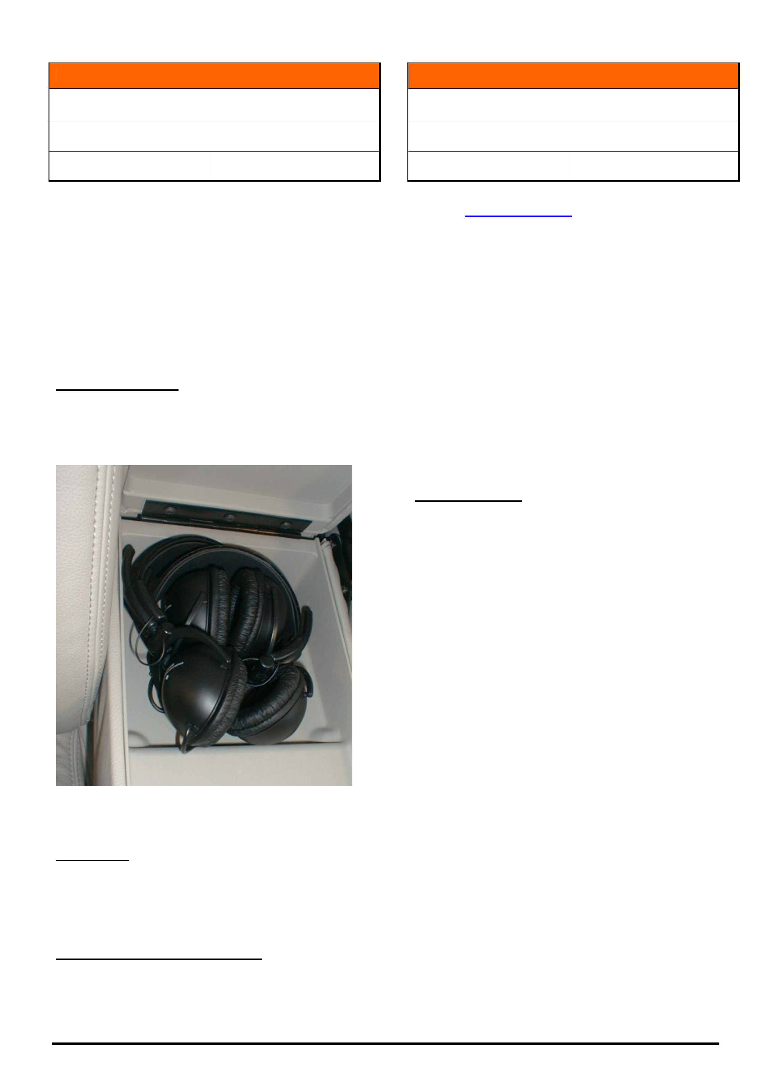
HOLDEN SERVICE TECHLINES___________________________________________________________________________NOVEMBER, 2005
17
Holden Techlines are written to inform technicians of conditions that may occur on some vehicles, and to provide information that could assist in the
proper service fix of a vehicle. If a condition is described, do not assume the service fix applies to a vehicle or that the vehicle will have that condition.
INFORMATION
DVD Changes From Panasonic to Blaupunkt
WL Caprice
Group 12 Ref. No. TL1005 - 0510
The DVD player in WL Caprice was changed from
Panasonic to Blaupunkt from vehicle tag L514978 (built
11th Oct 2005).
This new Blaupunkt system is able to play DVD's, audio
CD's, MP3's and Video CD's. It includes a new remote
control and new Blaupunkt headphones.
The headphone jacks are now located under the
headrest. In addition, an input jack located on the left-front
seat headrest allows audio and video connection from an
auxiliary device such as a camcorder or video game unit.
Headphone Storage
The headphones are to be stored one inside the other
(see picture) to fit within the centre armrest storage
compartment. This action will need to be performed at
Predelivery.
Figure 1. Shows arrangement of new headphones in
storage compartment
Diagnostics
In short term – refer draft version on Lionheart. Refer
Service Techlines\Advanced Information
Longer term - Final version will be on SIP.
Warranty Changeover Procedure.
In the event a warranty replacement unit is required,
refer to procedure on “Lionheart” which is found as
follows - Service Bulletins / Category / Special warranty
Component Replacement
INFORMATION
Ethanol Fuel Usability
All Post - 1986 Holden Vehicles
Group 6M Ref. No. TL1011 - 0510
The information shown below is taken from the Holden
website (www.holden.com.au). Customers can be referred
to the website for additional information should there be
any need.
Holden vehicles manufactured since 1986 will operate
satisfactorily on Ethanol fuel blend “E10”, with the
exception of the following vehicles that do not operate
satisfactorily on E10 fuel:
Apollo (1/87 - 7/89),
Nova (2/89 - 7/94),
Barina (1985 - 1994),
Drover (1985 - 1987),
Scurry (1985 - 1986),
Astra (1984 - 1989).
Owners of these vehicles should refer to the vehicle's
Owner's Manual for recommended fuel usage.
Purchasing fuel
When purchasing fuel, Holden recommends that
vehicles are operated on fuel containing no more than
10% ethanol.
Purchasing your fuel from a reputable retailer may
reduce the risk of purchasing fuel containing more than
10% ethanol or other abnormal properties. Under no
circumstances should you use fuel containing more
than 10% ethanol.
Use of such fuels may result in engine malfunction,
starting and operating difficulties, and materials
degradation. These adverse effects could result in
permanent damage to your vehicle.
It is also important to note that when ethanol blends
are used, fuel consumption can be expected to
increase due to the lower energy content of ethanol. It
is important to note the use of any fuel, other than the
fuel specified in the vehicle's Owner's Manual, may
seriously damage your vehicle and may void your
Warranty. Only good quality, clean fuel should be
used.
The use of fuel containing more than 10% ethanol may
also affect your New Vehicle Warranty.
HOLDEN SERVICE TECHLINES___________________________________________________________________________NOVEMBER, 2005
20
Holden Techlines are written to inform technicians of conditions that may occur on some vehicles, and to provide information that could assist in the
proper service fix of a vehicle. If a condition is described, do not assume the service fix applies to a vehicle or that the vehicle will have that condition.
SERVICE FIX
Erratic Fuel Gauge Operation in the Lower Half
of the Tank.
VZ / WL (excluding Gen 4 HSV)
Group 12 Ref. No. TL0975-0510
PROBLEM DESCRIPTION
Customers may complain that their fuel gauge is
erratic in the lower half of the tank or the low fuel
warning operates intermittently when the fuel level is
not low.
PRODUCTION RECTIFICATION
Revised fuel gauge calibrations were introduced over a
one week period ending in the production breakpoint
below.
Build Date: ISO VIN:
05/10/2005 6G1ZK14F96L516298
SERVICE RECTIFICATION
The revised calibrations are available on TIS 2000 CD
65 which was delivered to dealers in mid October
2005.
If presented with a vehicle where the customer advises
of the above condition perform the following steps:
1. Prior to performing any programming, observe and
note the position of the fuel gauge (e.g. ¼, ½, ¾ or
full).
2. Re-program the Instrument cluster as per the
standard SPS (Service Programming System)
process using Tech 2 and TIS 2000 version 65 or
later.
NOTE: For detailed instruction on this process
refer to Holden Lionheart portal, Service Techlines,
Section OD – TIS, “Reprogramming Procedure –
Instrument Cluster SPS”.
3. Re-program the ECU or PCM (engine or
powertrain control module) as per the standard
SPS (Service Programming System) process
using Tech 2 and TIS 2000 version 65 or later.
NOTE: For detailed instruction on this process
refer to Holden Lionheart portal, Service Techlines,
Section OD – TIS, “Reprogramming Procedure –
Engine ECU / PCM SPS”.
4. Re-program the Fuel Gauge Calibration in the
instrument cluster using Tech 2 software version
14.502 or later from TIS 2000 version 65 or later.
NOTE: For detailed instruction on this process
refer to Holden Lionheart portal, Service Techlines,
Section OD – TIS, “Reprogramming Procedure –
Instrument Cluster Fuel Gauge calibration”.
5. Once all programming is complete ensure the fuel
gauge returns to a similar position as noted in step 1.
NOTE: When the ignition is first switched on it may
take several minutes to display the original fuel
level.
CAUTION:
Software downloaded from TIS 2000 CD 65 or later is
not compatible with old instrument cluster software,
old engine ECU / PCM software or old fuel gauge
calibration from earlier releases of TIS 2000.
Therefore these three files must be used as a set
whenever programming an engine control module,
instrument cluster or fuel gauge calibration.
For example,
- If you re-program the engine control module you must
re-program the instrument cluster and fuel gauge
calibration using software from TIS 2000 CD 65 or later.
- If you replace & re-program the instrument cluster
module you must re-program the engine control module
and fuel gauge calibration using software from TIS 2000
CD 65 or later.
- If you re-program the fuel gauge calibration you must
re-program the engine control module and instrument
cluster using software from TIS 2000 CD 65 or later.
WARRANTY CLAIM INFORMATION
Description Fuel Gauge Calibration
Upgrade
Labour Op. No. N000493
V6 0.5 hrs Time
V8 0.4 hrs
Failure Code N0057
NOTE: Labour operation number and time covers
instrument cluster, ECU / PCM and fuel gauge re-
programming.
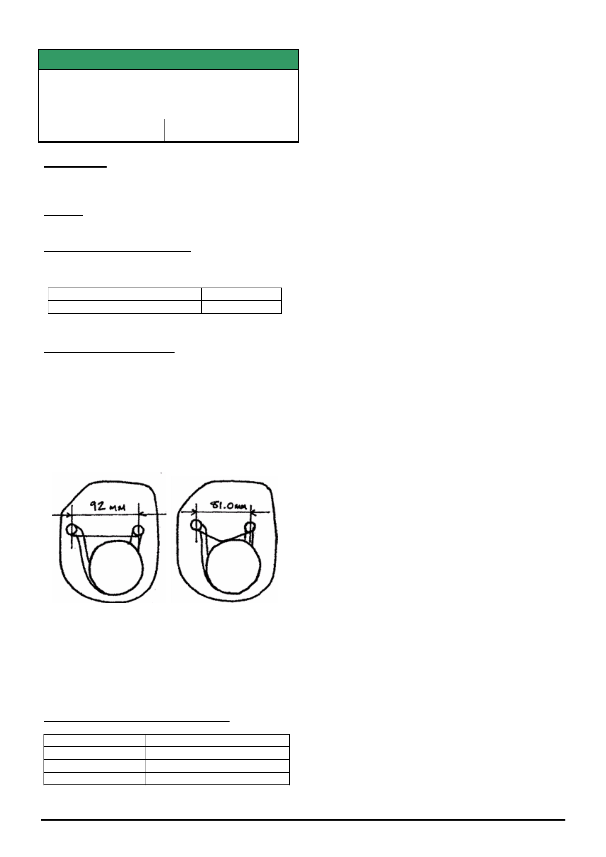
HOLDEN SERVICE TECHLINES___________________________________________________________________________NOVEMBER, 2005
21
Holden Techlines are written to inform technicians of conditions that may occur on some vehicles, and to provide information that could assist in the
proper service fix of a vehicle. If a condition is described, do not assume the service fix applies to a vehicle or that the vehicle will have that condition.
SERVICE FIX
Rear Muffler Rattle.
VZ Wagon & Sedan with 175 Kw V6
Group 8 Ref. No. TL1006 - 0510
CONDITION
A rattle may be generated if the rear muffler makes
contact with the heat shield.
CAUSE
Insufficient tension on the rear muffler hanger bracket.
CORRECTION – Production
Revised mufflers with reduced clearance between the
hanger bracket pins have been fitted to vehicles from:
ISOVIN: Built Date:
**********L428040 08/04/05
CORRECTION – Service
Summary: After verifying that vehicle has condition as
described above, modify the hanger bracket on the muffler as
follows.
1. Remove hanger bracket rubber bushes.
2. Reduce the distance between the hanger bracket
pins on the muffler by 11mm (from 92mm to
81mm) as shown in Figure 1.
A B
Figure 1.
3. The flat brace between the hanger pins will need
to be pushed down to facilitate closing the distance
between the pins - see Figure 1, View B.
4. Reinstall hanger bracket rubber support bushes.
WARRANTY CLAIM INFORMATION
Description Modify hanger bracket pins
Labour Op. No. L000257
Time 0.2 hr
Failure Code L0028 rattles
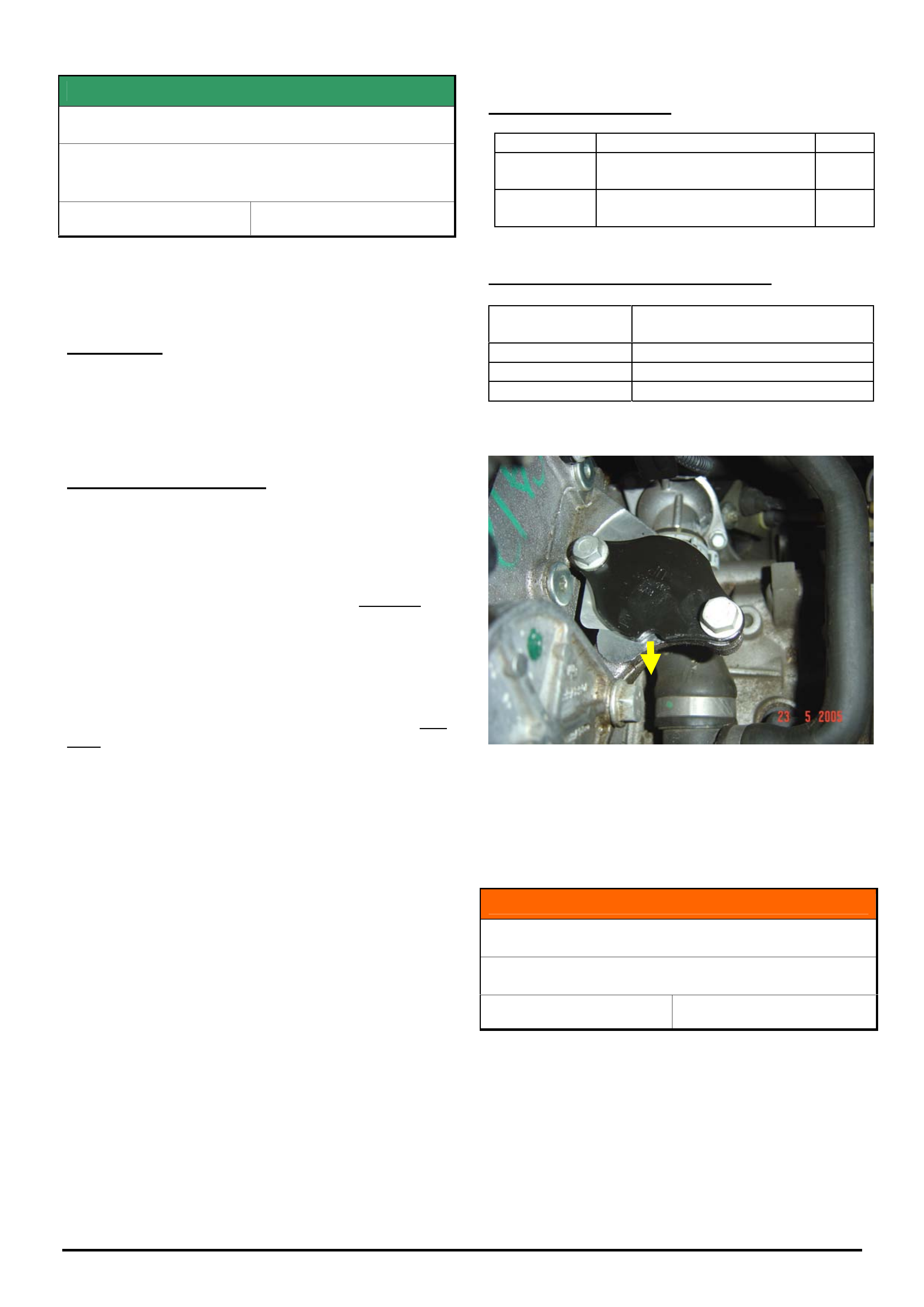
HOLDEN SERVICE TECHLINES___________________________________________________________________________NOVEMBER, 2005
22
Holden Techlines are written to inform technicians of conditions that may occur on some vehicles, and to provide information that could assist in the
proper service fix of a vehicle. If a condition is described, do not assume the service fix applies to a vehicle or that the vehicle will have that condition.
SERVICE FIX
EGR Malfunction
ZC Vectra, TS Astra, TT Zafira,
- with Z22SE engine
Group 6C Ref. No. TL0919B - 0510
This Techline supersedes TL0919A-0509 in Issue 9, 2005. It
is updated with advice that this fix does not apply to TS
and TT models built prior to Model Year 2003. Refer engine
number breakpoints below.
CONDITION
Drivers may report that their vehicle runs rough or
lacks power.
The telltale light comes on and P1404 DTC is set
(EGR valve stuck).
CORRECTION – Service
The correction procedure detailed below applies to the
following vehicles:
ZC Vectra with Eng. No. built before Z22 SE11 293 531
TS Astra Sri MY 2003 vehicles (and later) built after the
following engine numbers.
11 133 945 - MT
11 131 764 - AT
TT Zafira Equipe MY 2003.5 and
TS Astra Convertible MY 2003 vehicles (and later) built
after the following engine numbers.
11 133 885 - MT
11 133 302 - AT
NOTE: The above Engine Number Breakpoints are
important as vehicles built prior to these Breakpoints
have a different engine management calibration and
catalytic converters. Incorrect application of the
correction procedure to pre breakpoint vehicles can
result in catalytic converter failure.
Procedure.
On complaint vehicles where diagnosis finds that an
EGR valve is faulty, it should not be renewed but
removed altogether as per the following procedure.
1. Close exhaust gas recirculation port with a cover
plate (Part No. 24575592). Replace gasket when doing
so. (Part No. 12570863). The groove on the plate has
to point in the direction of the radiator with the plate
labelling facing upwards.
2. Fix the redundant wiring harness connector with a
cable strap (face connector opening to rear of vehicle).
3. Program ECU with SPS as of TIS 2000, CD 56 and
onward (select without EGR).
PARTS INFORMATION
Part No.: Partfinder Name Qty:
24575592 Cover plate- EGR valve
opening
1
12570863 Gasket - EGR valve to cyl
head
1
WARRANTY CLAIM INFORMATION
Description Remove EGR valve, add cover
plate, and reprogram ECU
Labour Op. No. J000776
Time 0.6 hr
Failure Code J0057 registers incorrectly
Figure 1. Shows EGR cover plate with groove facing
towards front of vehicle.
INFORMATION
Fuel Gauge Fixes Quick Reference
VY, V2 II & III, WK, VZ & WL
Group 12 Ref. No. TL1015 - 0510
To assist technicians in diagnosing fuel gauge
complaints on the above models, a summary of
various fuel gauge fixes which have previously been
published as Techlines is provided on the back page
of this issue.
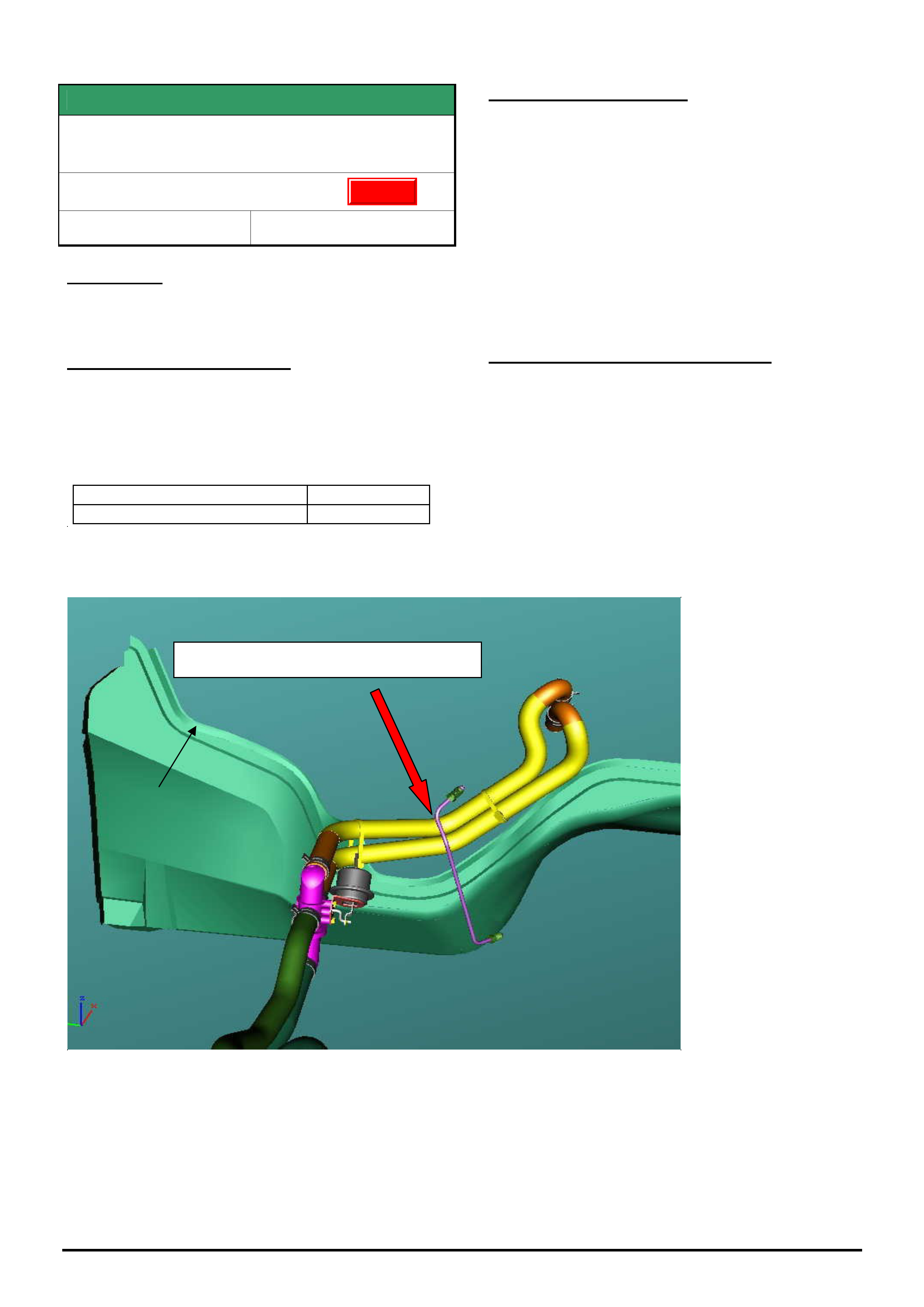
HOLDEN SERVICE TECHLINES___________________________________________________________________________NOVEMBER, 2005
23
Holden Techlines are written to inform technicians of conditions that may occur on some vehicles, and to provide information that could assist in the
proper service fix of a vehicle. If a condition is described, do not assume the service fix applies to a vehicle or that the vehicle will have that condition.
SERVICE FIX
Heater Hose Rubs Through On Rear Of
Cylinder Head
VY, VZ, Gen III Engine & M/T
Group 2 Ref. No. TL 0867 - 0510
CONDITION
There have been isolated cases where the heater
hose has been damaged due to contact with the rear
of the right hand side cylinder head.
CORRECTION – Production
A revised shape clutch pipe has been introduced into
production to provide greater clearance between the
heater hoses and cylinder head.
The revised clutch pipe has been fiitted to vehicles
from:
ISOVIN: Built Date:
**********L484030 01/08/05
CORRECTION – Service
On any vehicle built prior to L484030 where the
heater hose is being replaced, route the new hose
between the clutch pipe and the dash panel as shown
in Figure 1.
Secure the heater hose to the clutch line with a cable
tie and adjust the hose to ensure there is maximum
clearance to the rear of the cylinder head.
For vehicles built after L484030 (with revised shape
clutch pipe) the heater hoses must be routed forward
of the clutch pipe.
WARRANTY CLAIM INFORMATION
Use Labour Times information in Warranty Information
section of current PV SIP CD
Figure 1.
Route hoses behind clutch pipe
Dash panel
glue track
Update

24
Holden Techlines are written to inform technicians of conditions that may occur on some vehicles, and to provide information that could assist in the proper service fix of a vehicle. If a condition is described, do not assume the
service fix applies to a vehicle or that the vehicle will have that condition.
Fuel Gauge Fixes Quick Reference - VY, V2 II & III, WK, VZ & WL
Group 12 Ref. No. TL1015- 0510
MODEL CONDITION BREAKPOINT TECHLINE REFERENCE
VY I & II / WK / V2 II & III
(excluding VY I Ute)
Fuel Gauge Intermittently Reads Incorrect Value
(May run out of fuel before the gauge reads empty)
L199047 (11/11/03)
TL605-0311 / 2003 Issue 11 Page 7
VY I & II Cab Chassis
(Crewman / Regular Cab / X8)
Fuel Gauge Problem Due To Auxiliary Pickup
(Can’t get enough fuel in the tank when the gauge reads empty)
V6 L288194 (08/06/04)
V8 L291976 (15/06/04)
TL0672-0405 / 2004 Issue 5 Page 5
VY I & II Ute & Cab Chassis
(Crewman / Regular Cab / X8
Erratic Gauge Operation within the full to 3/4 range
(Gauge drops to ¾ and then goes back to full when the ignition is cycled)
L304521 (20/07/04)
TL0778-0408 / 2004 Issue 8 Page 14
VY / WK / V2 II & III
Implausible DTE & slow to return to full
(Excessively high or low distance to empty)
(Fuel gauge does not display full for a long period of time after filling)
No production break point
Published via February 2005 SMA Handout
(Refer TAS)
VZ
Fuel gauge indicates higher than actual
(Bent sender arm)
L345644 (06/10/04)
TL0809-0410 / 2004 Issue 10 Page 10
VZ Gen III Ute
Fuel gauge will not display full after refilling the fuel tank
L390626 (21/01/05)
TL0844-0501 / 2005 Issue 1 Page 5
VZ / WL V6 Sedan & Wagon
Fuel gauge inaccuracy
(May run out of fuel before the gauge reads empty)
L382346 (09/12/04)
TL0845-0501 / 2005 Issue 1 Page 5
VZ / WL
Low fuel warning operation clarification
(To clarify complaints of low fuel warning coming on too early)
Information to clarify operation
TL0891-0505 / 2005
VZ V6 Ute
High reserve
(Can’t get enough fuel in the tank when the low fuel light comes on)
L444651 (18/05/05)
TL0952 – 0506 / 2005 Issue 6 Page 8
VZ / WL
Erratic gauge operation in the lower half of the tank
(When the tank is ¼ full the gauge will display between ½ and empty if the ignition is
cycled on an incline)
L516298 (05/10/05)
TL0975-0510/ 2005 Issue 10
HOLDEN SERVICE TECHLINES___________________________________________________________________________DECEMBER, 2005
8
Holden Techlines are written to inform technicians of conditions that may occur on some vehicles, and to provide information that could assist in the
proper service fix of a vehicle. If a condition is described, do not assume the service fix applies to a vehicle or that the vehicle will have that condition.
DIAGNOSIS HINT
Rattle Caused By Heater Tap Touching
Ignition Coil
VZ & WL with HFV6
Group 2 Ref. No. TL0801-0511
Prior to investigating any rattle or buzz suspected of
coming from the Instrument Panel, it is recommended
to first check that the heater tap is not rattling against
the RH rear ignition coil.
Since the start of VZ production, a strip of insulating
foam has been fitted between the heater tap and RH
rear ignition coil to prevent a rattle or buzz noise.
However, it is possible that this insulating strip may
have dislodged or removed during service.
If required, install a suitable insulating strip between
the heater tap and the coil.
DIAGNOSIS HINT
Low Traction Event Occurs Unnecessarily
During Take Off.
VZ with M/T and traction control
Group 5 Ref. No. TL1042-0511
CONDITION
During take off, a low traction event occurs
unnecessarily. Low traction indicator is illuminated.
CAUSE
This condition could be due to insufficient air gap
between rear wheel speed sensors and tone wheel.
CORRECTION
Check air gap measurement and adjust if required.
1. Check air gap of both of the rear wheel speed
sensors.
2. Air gap needs to be 1.5mm.
3. If less than 1.5mm, use shim part number
90278359 to achieve the correct air gap spacing.
PARTS INFORMATION
Part No.: Description Qty:
90278359 Shim 1
Update
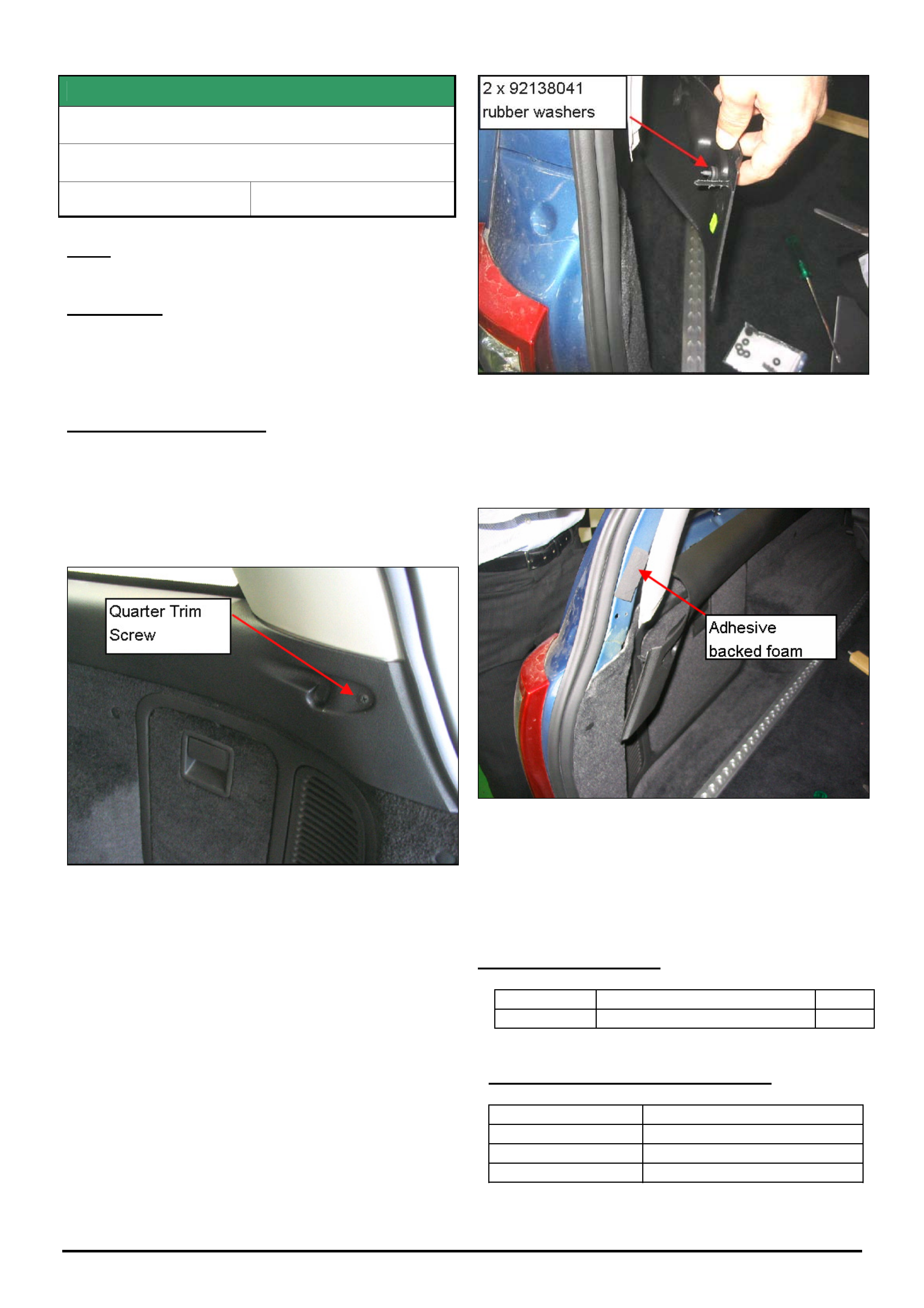
HOLDEN SERVICE TECHLINES___________________________________________________________________________DECEMBER, 2005
9
Holden Techlines are written to inform technicians of conditions that may occur on some vehicles, and to provide information that could assist in the
proper service fix of a vehicle. If a condition is described, do not assume the service fix applies to a vehicle or that the vehicle will have that condition.
SERVICE FIX
Poor Retention Of Cargo Blind At D Pillar
VZ Wagon
Group 1 Ref. No. TL1029 - 0511
Note:The cargo blind should not be replaced for this
condition.
CONDITION
The cargo blind may detach from the D-pillar locators
when vehicle is driven on rough roads or with heavy
closing of the tailgate.
CORRECTION – Service
Summary: Pack out the interior trim at D-pillar to
provide better retention of the cargo blind in its
extended position.
1. Remove the rear quarter trim screw from both
sides.
Figure 1
2. Pack out the D-pillar trim by fitting two rubber
washers on the quarter trim screw, between the
quarter trim and body panel.
Figure 2
3. Remove the D-pillar trim and install 10mm thick
(approx.) adhesive backed foam in the location
shown in figure 3. This helps to align the quarter
and D-pillar trims.
Figure 3
4. Reinstall the trims and blind. Check the retention
of the blind and fitment of trim. Add or remove
washers or tape where required to improve fit.
PARTS INFORMATION
Part No.: Description Qty:
92138041 Washer 4
WARRANTY CLAIM INFORMATION
Description Pack out rear quarter trims
Labour Op. No. C000544
Time 0.2 hr
Failure Code C0027 loose
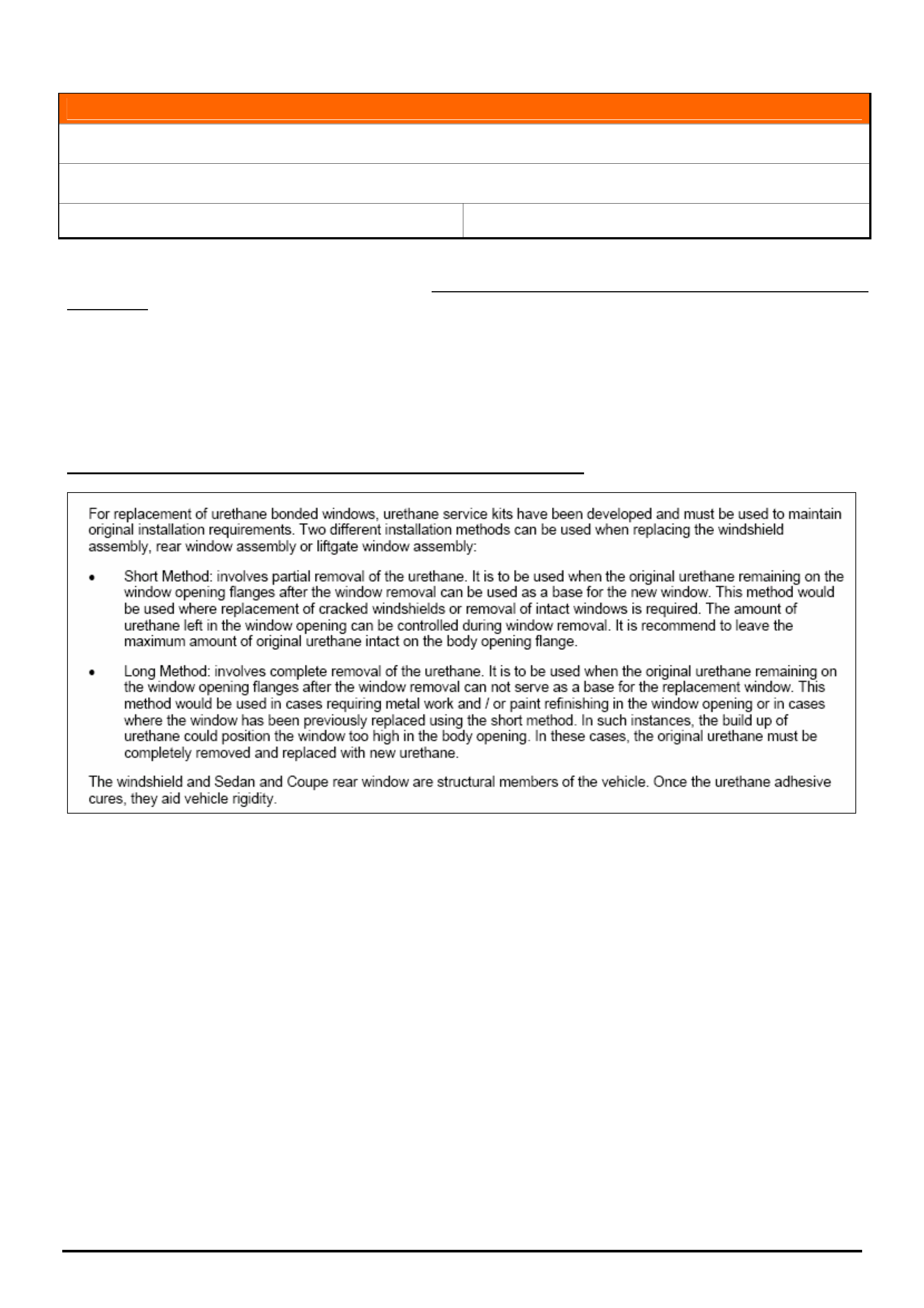
HOLDEN SERVICE TECHLINES___________________________________________________________________________DECEMBER, 2005
11
Holden Techlines are written to inform technicians of conditions that may occur on some vehicles, and to provide information that could assist in the
proper service fix of a vehicle. If a condition is described, do not assume the service fix applies to a vehicle or that the vehicle will have that condition.
INFORMATION
Use of Correct Adhesives For Fixed Glass
All Vehicles
Group 1 Ref. No. TL1002 - 0511
Dealers should be aware of the importance of using the correct adhesive when replacing (or subletting the
replacement of) fixed glass windows in any vehicle. Use of an incorrect adhesive could affect the structural integrity
of the body.
Below is an example extracted from Passenger Vehicle SIP, explaining some of the requirements when replacing
fixed glass. Refer to SIP for a full description of service procedures and requirements.
Please provide a copy of the relevant SIP procedure to your sublet repairer to comply with when installing fixed
glass.
PV SIP - Section 6A1 Stationary Windows – General Information
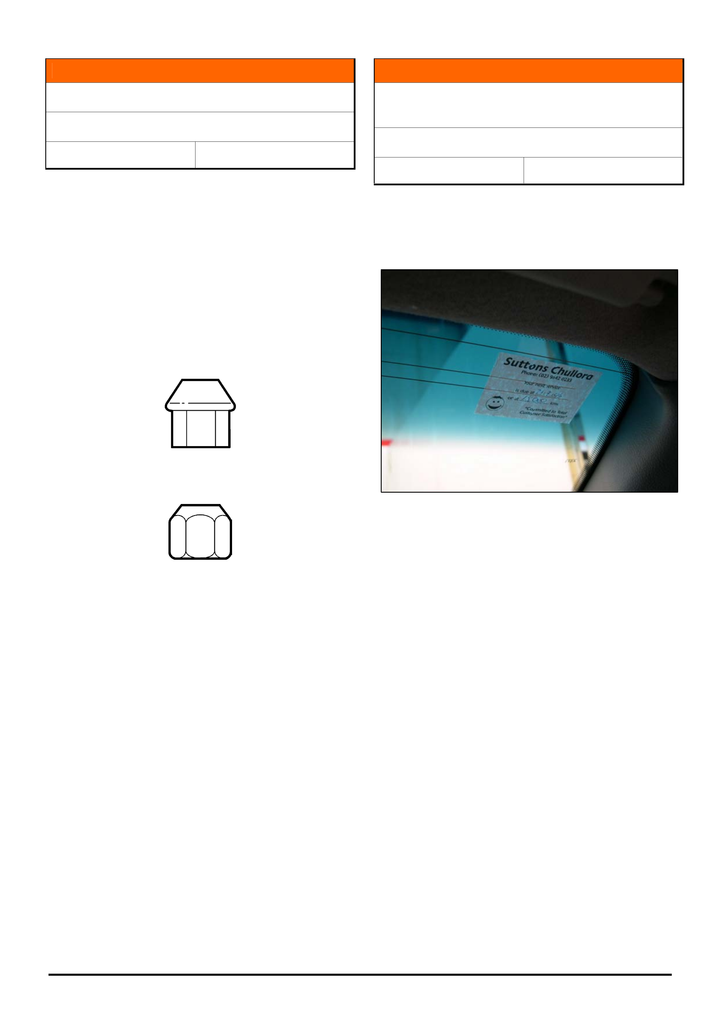
HOLDEN SERVICE TECHLINES___________________________________________________________________________DECEMBER, 2005
12
Holden Techlines are written to inform technicians of conditions that may occur on some vehicles, and to provide information that could assist in the
proper service fix of a vehicle. If a condition is described, do not assume the service fix applies to a vehicle or that the vehicle will have that condition.
INFORMATION
Commonisation of Wheel Nuts
VZ
Group 10 Ref. No. TL0801-0511
Commencing on the 5/11/2005, (vehicle tag L532313)
all vehicles supplied with steel wheels will now be fitted
with the nut designed for use with alloy wheels.
Steel wheel nut part number 92015262 will be replaced
by alloy wheel nut part number 22526184.
The alloy wheel nut has a longer taper which is
suitable for use on both alloy and steel wheels. Refer
figure 1
Figure 1. Alloy wheel nut p/n 22526184
Figure 2. Steel wheel nut p/n 92015262
INFORMATION
Precaution for Removal of Dealer Service
Reminder Label
JF Viva Hatch & Wagon
Group 12 Ref. No. TL1041- 0511
This vehicle is fitted with a glass mounted radio
antenna which is adhered to the right hand top inside
corner of the front windscreen where the service label
is usually located, as per figure 1.
Figure 1
When adhering service reminder labels to these
vehicles do not locate it on top of the radio antenna.
Please take care not to damage the radio antenna
when removing the service reminder label from
windscreen.
Do not use sharp tools to remove the service
reminder label, for example razor blades or
scrapers.
Damage caused to the antenna circuit when
removing the service reminder label will not be
accepted as a warranty claim.
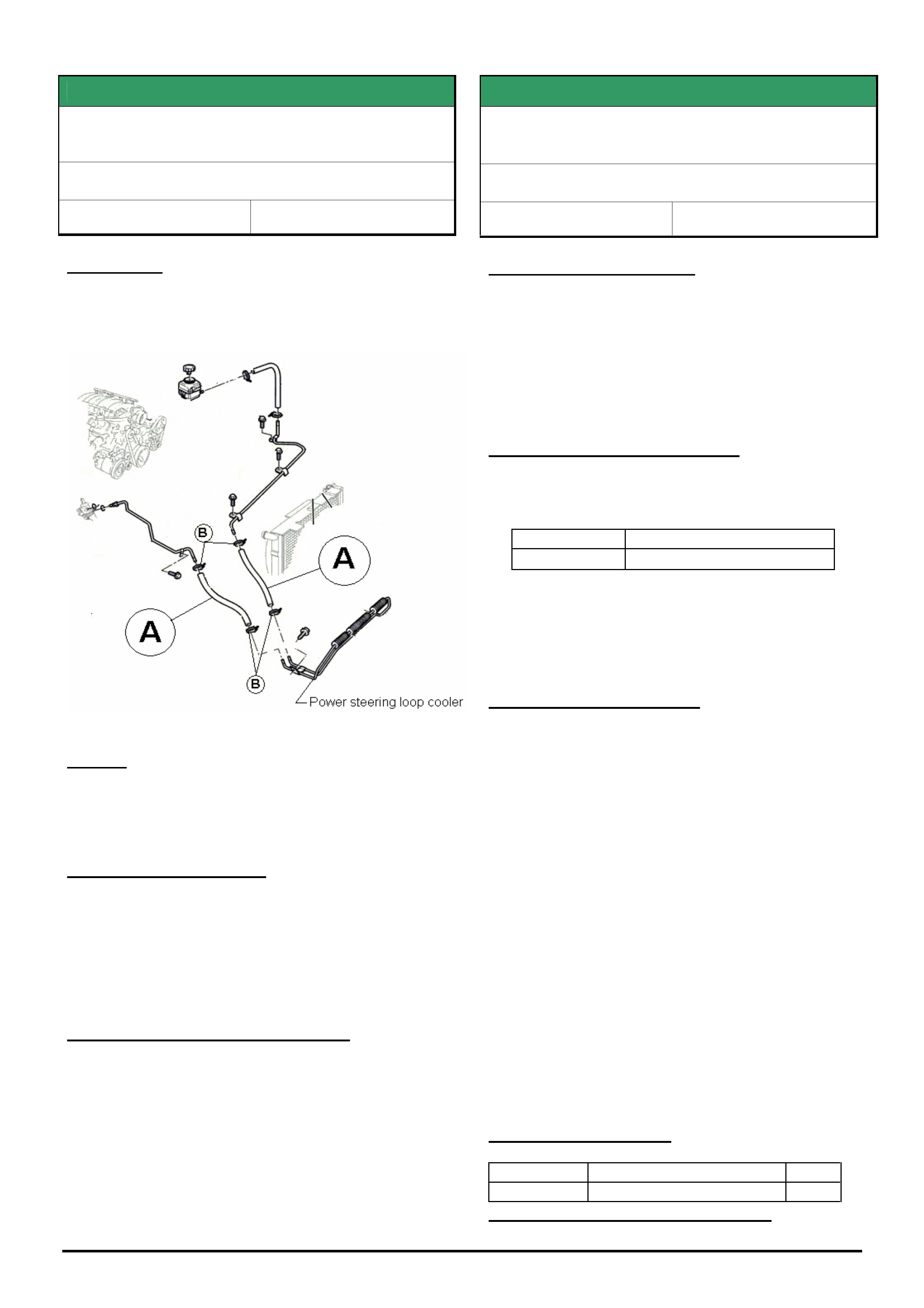
HOLDEN SERVICE TECHLINES___________________________________________________________________________DECEMBER, 2005
13
Holden Techlines are written to inform technicians of conditions that may occur on some vehicles, and to provide information that could assist in the
proper service fix of a vehicle. If a condition is described, do not assume the service fix applies to a vehicle or that the vehicle will have that condition.
SERVICE FIX
Power Steering Cooler Hose Leaks
VZ, WL
Group 9 Ref. No. TL1001- 0511
CONDITION
On some vehicles, power steering fluid may leak from
the cooler hose connections with hose clamps. Refer
item B in following figure.
CAUSE
Compression “set” of the hose after installation in
production causes the hose clamp to relax tension at
the hose to pipe connection.
CORRECTION – Service
1. On vehicles with the above condition, re-tension
hose clamps to 3 Nm.
2. If hose clamp is not sealing and is visibly deformed
replace hose clamp.
3. DO NOT REPLACE HOSE UNLESS DAMAGED.
WARRANTY CLAIM INFORMATION
Use Labour Times information in Warranty Information
section of current PV SIP CD
SERVICE FIX
PIM Replacement Prior To Reprogramming
Engine ECU for Vehicles Built Prior to 17/11/05
VZ , WL, Gen 4 HSV
Group 12 Ref. No. TL1033-0511
PROBLEM DESCRIPTION
Due to an incompatibility issue between the latest
engine ECU calibration and the Powertrain Interface
Module (PIM), it will be necessary to install a revised
PIM prior to reprogramming the engine ECU’s in any
VZ / WL series HSV vehicle fitted with a Gen 4 engine
using TIS 2000 CD 66 (or later).
PRODUCTION RECTIFICATION
A revised PIM has been fitted in production from the
following breakpoint.
Build Date: ISO VIN:
17/11/05 6G1ZK42U45L535469
Note: A significant number of vehicles built prior to the
breakpoint above have been rectified at HSV and can
be identified by an “X” in co-ordinate E-1 of the service
history label .
SERVICE RECTIFICATION
When presented with a HSV Gen 4 which requires re-
programming of the engine ECU for any reason
perform the following,
1. Check co-ordinate E-1 of the vehicle service
history label (located on the inside of the fuse
panel cover) to ensure the vehicle has not
previously had the revised PIM installed.
2. Ensure your Tech 2 is updated with software
version 14.601 or later (available from TIS 2000
CD 66).
3. Refer to Passenger Vehicle SIP for the PIM
replace and program procedure.
4. Install the new PIM part number 92181129.
5. Mark co-ordinate number E-1 of the vehicle
service history label for ease of future
identification.
PARTS INFORMATION
Part No.: Description: Qty:
92181129 Revised PIM 1
WARRANTY CLAIM INFORMATION
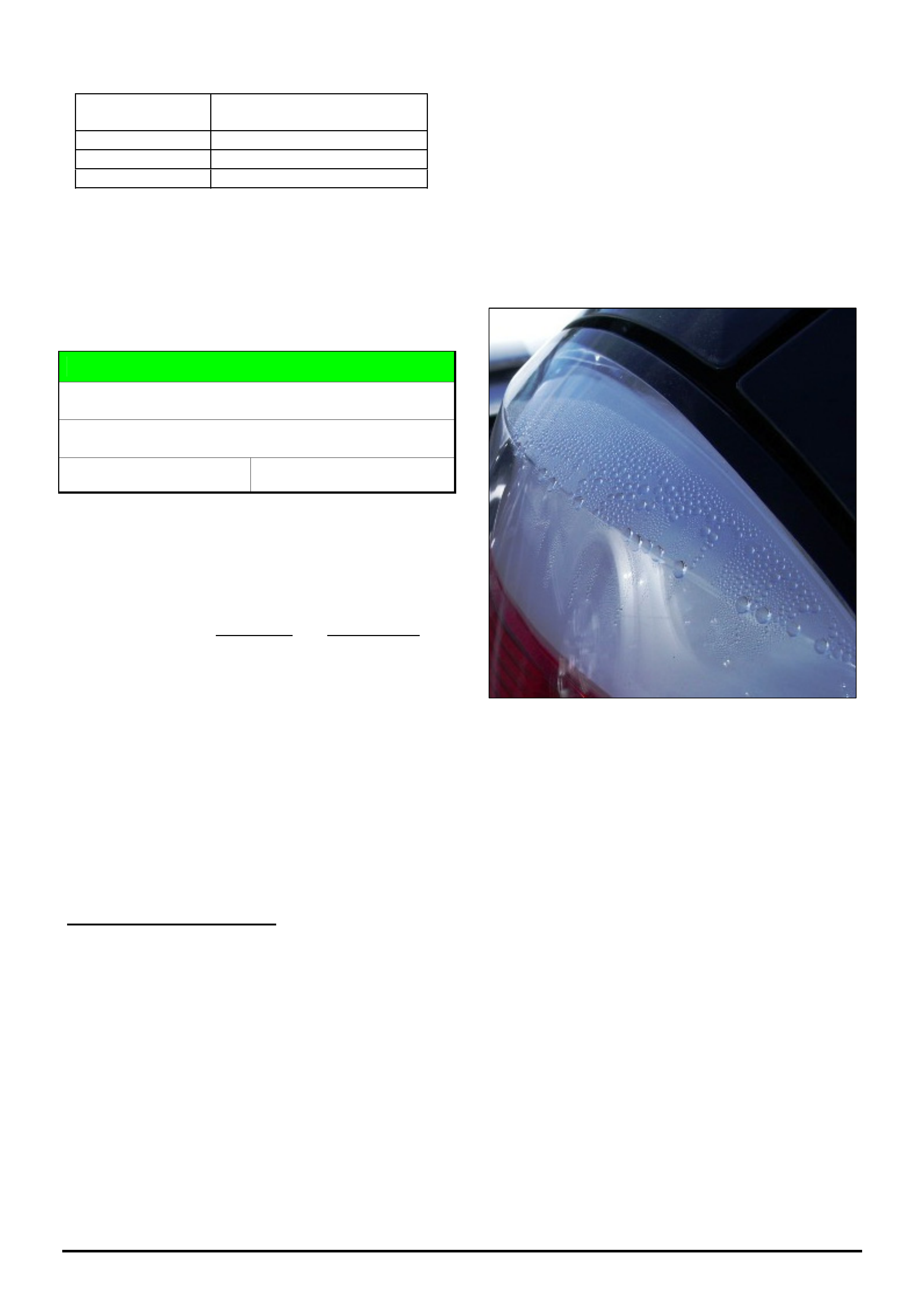
HOLDEN SERVICE TECHLINES___________________________________________________________________________DECEMBER, 2005
14
Holden Techlines are written to inform technicians of conditions that may occur on some vehicles, and to provide information that could assist in the
proper service fix of a vehicle. If a condition is described, do not assume the service fix applies to a vehicle or that the vehicle will have that condition.
Description HSV Gen 4 PIM
Replacement
Labour Op. No. J000794
Time 0.4 Hrs
Failure Code N0095
Note: This labour operation number can only be
claimed once. All vehicles rectified at HSV have been
excluded.
DIAGNOSIS HINT
Tail lamp – Condensation or Water Entry
AH Astra
Group 12 Ref. No. TL1044-0511
Many AH tail lamp assemblies are being replaced
unnecessarily for complaint of “condensation” or “water
entry”.
This techline is provided to help technicians
understand the AH tail lamp design and how to
differentiate between water entry and condensation.
These are vented lamps with clear lenses which are
more prone to display visible fogging (condensation).
Under certain climatic conditions (high humidity) when
vehicles are parked after use, the vent system will
draw moisture-laden air into the lamp which
condenses on the lens as it cools down. This fogging
will usually disperse when the vehicle is driven, or if
the tail lamps are left on for 3-4 minutes. If a customer
uses their tail lamps on a rainy day, or washes the
vehicle after having the tail lamps on, they could
expect to notice condensation some time after the
vehicle has been parked - this is normal.
DIAGNOSIS PROCEDURE
In the event a customer complains of condensation in
tail lamps, inspect the tail lamp to determine if there
are signs of normal fogging, or if the lamp has water
entry due to poor sealing.
Condensation (Fogging).
Condensation will appear as a mist on the lens
however will not have distinguishable water droplets.
This normally needs no dealership action, as the
fogging will disperse during the time the vehicle is left
standing or after 3-4 minutes with the lamps on. As a
check in the dealership, leave tail lamps on for 5 to 10
minutes max. and recheck if condensation has
disappeared. If condensation is still present, then the
lamps are more likely to have the condition of “water
entry”.
Water Entry.
If a lens has severe condensation with water droplets
then investigation into the cause of water entry must
be carried out. Any obvious cause of water entry (e.g.
connector covers left off) should be corrected and
lamps dried out by leaving switched on for 10 minutes.
If the tail lamp does not clear, the lamp will require
replacement. A clear description of diagnosis should
be quoted in the 3C’s information tag when the lamp is
returned to Repac.
Figure 1. Water Entry (Heavy droplets)
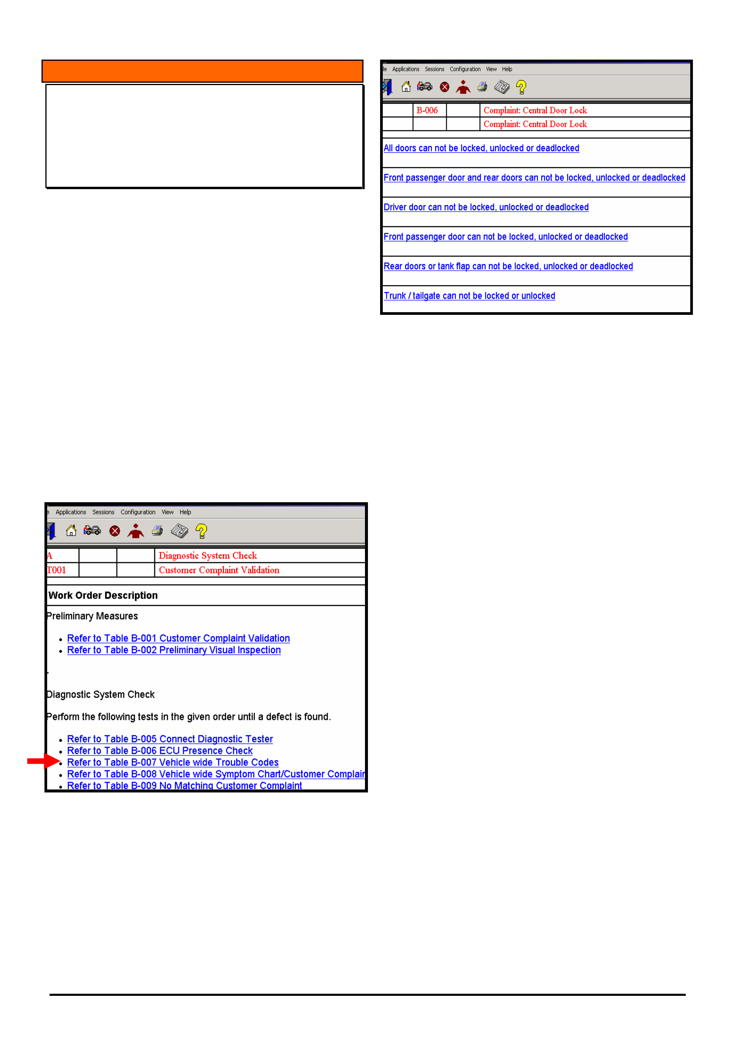
HOLDEN SERVICE TECHLINES___________________________________________________________________________DECEMBER, 2005
15
Holden Techlines are written to inform technicians of conditions that may occur on some vehicles, and to provide information that could assist in the
proper service fix of a vehicle. If a condition is described, do not assume the service fix applies to a vehicle or that the vehicle will have that condition.
INFORMATION
TIS 2000 Diagnostic Charts for Customer
Complaints/Symptoms When no DTC’s are set
ZC Vectra , AH Astra
(GROUP OB) TL1049-0511
For all electronic systems in ZC and AH models, TIS
2000 provides diagnostic charts for customer
complaints/vehicle symptoms when there are no DTC’s
stored.
These diagnostic charts are found via the following
selection path:
- Checking procedures,
- Vehicle / Vehicle Related diagnostic procedure,
- Guided Electronic system Diagnosis
Then, from the main selection screen, select “vehicle
wide symptom chart/customer complaint” as shown in
Figure 1.
Then select the electronic system the fault belongs to.
For example; ‘Central Door Locks’ then choose the
relevant fault: Refer to figure 2.
Figure 1
Figure 2
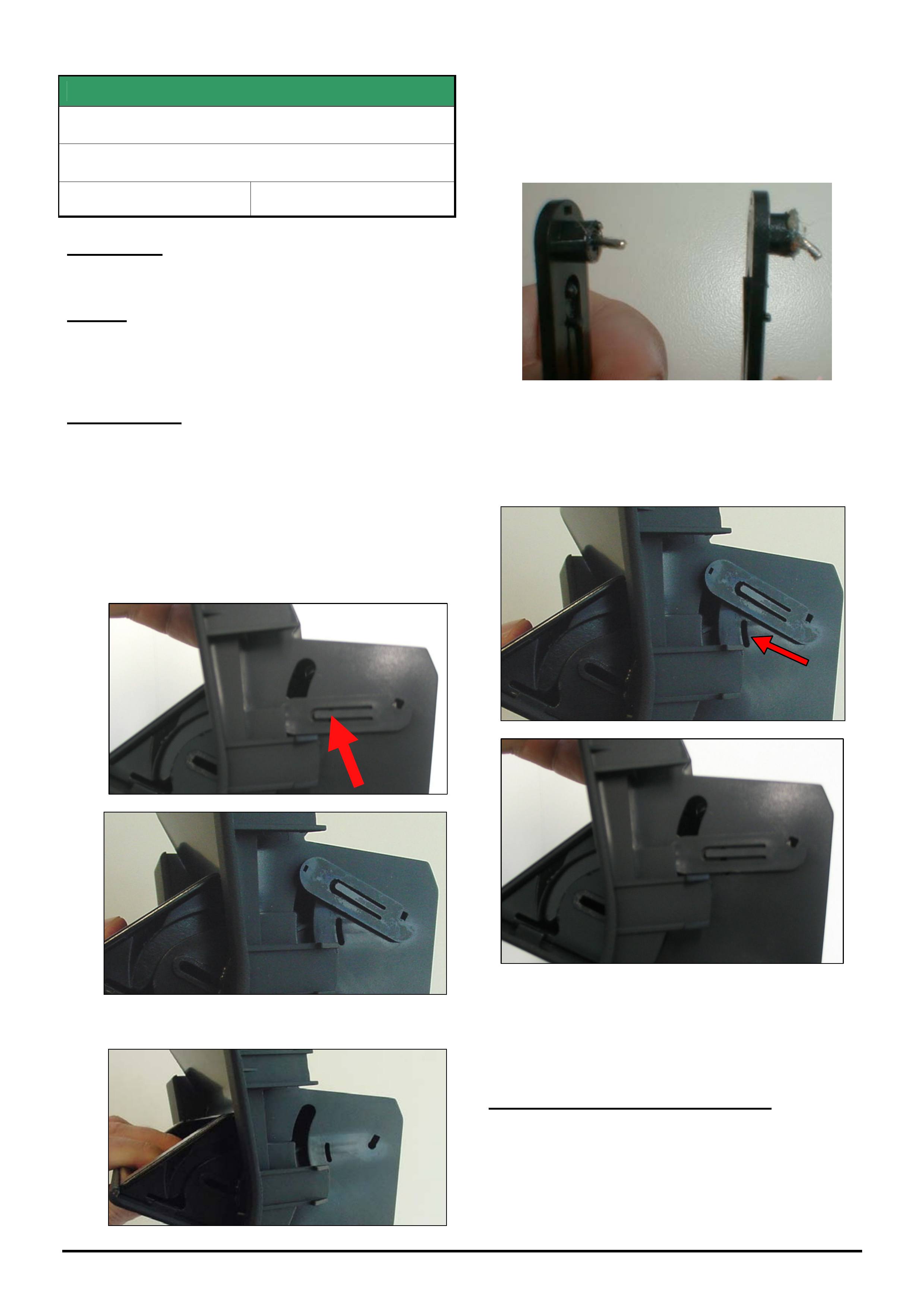
HOLDEN SERVICE TECHLINES___________________________________________________________________________DECEMBER, 2005
16
Holden Techlines are written to inform technicians of conditions that may occur on some vehicles, and to provide information that could assist in the
proper service fix of a vehicle. If a condition is described, do not assume the service fix applies to a vehicle or that the vehicle will have that condition.
SERVICE FIX
Ashtray Door Not Staying Closed
TS Astra
Group 1 Ref. No. TL1009 - 0511
CONDITION
Ashtray door will not stay closed.
CAUSE
The above condition can occur if the ashtray door is
forced open by pulling instead of pushing to open. This
action deforms the locking pin on the lever arm.
CORRECTION
Summary: DO NOT REPLACE THE ASHTRAY.
Instead, remove the ashtray, and rework bent pin in
linkage arm as per following procedure.
STEP 1. With the ashtray door open, use a small
screwdriver to carefully lift the plastic tang in the centre of
the linkage arm (at location of arrow). Whilst lifting the
tang, move the arm fully upwards as shown in the 2nd
photo to enable it to be withdrawn.
STEP 2. Remove linkage arm from ashtray.
STEP 3. Carefully straighten the pin as shown in the
following photograph.
NOTE: If the pin cannot be successfully straightened
replace the ashtray assembly.
STEP 4. Refit linkage arm and rotate downwards until
the tang locates into the slot as shown by arrow.
STEP 5. Reinstall ashtray into console.
WARRANTY CLAIM INFORMATION
Use Labour Times information in Warranty Information
section of current PV SIP CD for Removal and
Replacement of the ashtray.
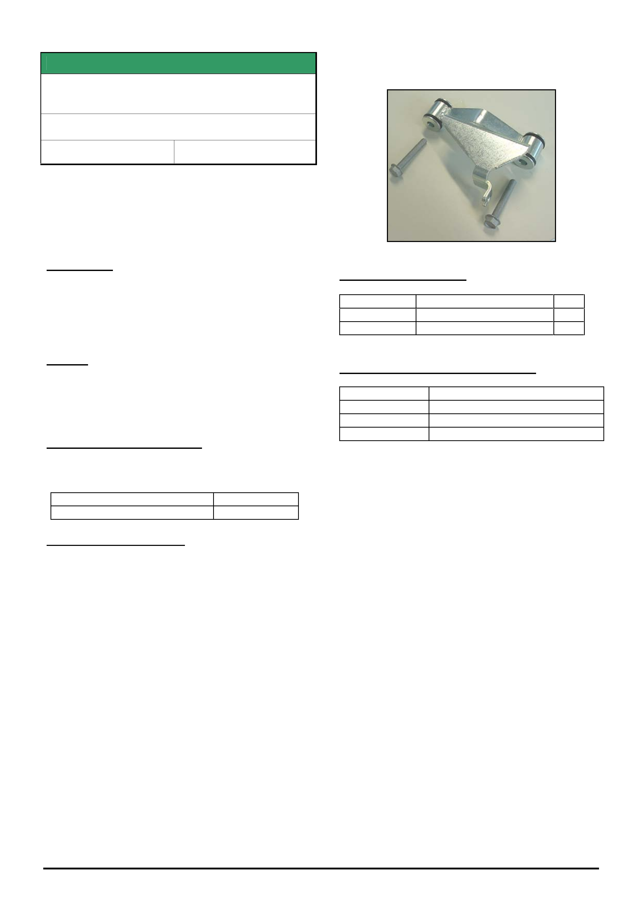
HOLDEN SERVICE TECHLINES___________________________________________________________________________DECEMBER, 2005
17
Holden Techlines are written to inform technicians of conditions that may occur on some vehicles, and to provide information that could assist in the
proper service fix of a vehicle. If a condition is described, do not assume the service fix applies to a vehicle or that the vehicle will have that condition.
SERVICE FIX
Transfer Case Noise Reduction (Isolated A/T
Shifter Cable Bracket)
VY & VZ - Adventra and Cross 8
GROUP 4 & 7B Ref. No. TL0721A-0511
This Techline supercedes the previous one in Issue 2,
March, 2005. It has been re-issued as there have been a
number of PIR’s mentioning this condition, where
technicians have not identified the service correction
detailed below. The information is also updated by adding
Model applications and Breakpoints.
CONDITION
It is possible for a minor “hash” noise (similar to a
synchro ring rattle noise) to be heard in the passenger
compartment. Reports say the condition may occur in
the range of 40 – 60 km/h on light acceleration or
deceleration.
CAUSE
This noise heard is normal transfer case internal gear
and bearing noises which are transmitted into the
passenger compartment via the solid attachment of the
A/T shift cable to the transmission case.
CORRECTION – Production
Revised brackets with insulating bushes have been
fitted to VZ vehicles from:
ISOVIN: Built Date:
**********L419407 18/04/05
CORRECTION – Service
Summary: After verifying that vehicle has symptoms as
described above, fit a new bracket assembly with new
attaching screws.
To fit these parts, refer to SIP section 7C4 for service
operation 2.2 – this procedure allows removal of the
A/T selector cable for access to the cable bracket on
the side of the transmission.
(The revised cable bracket is similar in appearance to
the original cable bracket, so its location and
orientation are easily defineable).
When attaching the cable bracket with the new screws,
Torque screws to 17&3 Nm.
The picture below shows the revised bracket and
screws:
PARTS INFORMATION
Part No.: Description: Qty:
92174776 Bracket Asm., A/T Cable 1
11098091 Screw, Bracket Mtg. 2
WARRANTY CLAIM INFORMATION
Description A/T Cable Bracket Asm - Replace
Labour Op. No. K503100
Time 0.6 hr
Failure Code K0040 - Noisy

HOLDEN SERVICE TECHLINES___________________________________________________________________________DECEMBER, 2005
18
Holden Techlines are written to inform technicians of conditions that may occur on some vehicles, and to provide information that could assist in the
proper service fix of a vehicle. If a condition is described, do not assume the service fix applies to a vehicle or that the vehicle will have that condition.
DIAGNOSIS HINT
Oxygen Sensor Replacement Precautions
VZ/WL
Group 6C Ref. No. TL1059- 0511
CONCERN
This information is supplied so that technicians are
aware of the possibility of oxygen (O²) sensor damage
and/or misdiagnosis and acts as a warning that such
damage and over-replacement of NFF parts will no
longer be accepted as warranty. This Techline should
be circulated to technicians and Warranty
Administrators.
A large number of oxygen sensors replaced under
warranty have been investigated and are shown to be
No Fault Found after testing.
Some exhibit damage to the sensor body, internal
ceramic or wiring harness, caused during replacement
by the use of incorrect or inappropriate tools.
These results indicate there may be possible confusion
in diagnosis and methods of replacement being used
by technicians; EG: ‘sets’ of sensors replaced instead
of one.
CAUSES
Diagnosis Error - Excessive Replacements -
A number of claims have occurred where multiple O²
sensors have been replaced (sets of 2 or 4).
Technicians must be aware that it is NOT necessary to
replace all sensors or sets of sensors, and it is rare to
need to replace more than one sensor.
Any replacement of more than one sensor must be
verified by reference to the diagnostics that were
carried out - in the CCC’s area of the warranty claim.
O² Sensor - Incorrect Removal Practices – Sensors
have been returned where there is damage to the O²
sensor or the wiring by the use of wrong tools EG:
Multi-grips, vice-grips or spanners that have slipped off
and distorted the sensor body and cracked the internal
ceramic element.
The nature of the sealant used on oxygen sensors
means that a very high torque load is required to
“break” the sealant (which hardens to a glass-like
material).
Sensors should be initially loosened with a flare nut or
with a proprietary sensor removal socket (various
types are available, such as slotted-side deep sockets
as used for sensor/thermal switch removal).
An open end spanner should only be used for initial
removal where there is restricted tool access.
These precautions ensure no damage is done to the
sensor or its wiring. Final removal can be done with an
open end spanner. An open-end spanner can be used
to refit the sensor, but the sensor removal tool/flare nut
spanner should be used to torque the sensor.
Do NOT cut O² sensor wiring during removal of any
sensor. O² sensors that have wiring cut will not be
accepted under warranty.
The SIP warning note is repeated here for reference:
Using incorrect tools (such as multigrips, vice-grips,
etc.) to remove sensors is not acceptable, as there is
the risk of damage to the sensor or its internal ceramic
section, if the tool should slip off, this makes root
cause evaluation impossible (the intent of returning
failed components is to allow root cause analysis
which allows rectification of production or manufacture
concerns that could cause customer concerns).
Unnecessary Replacements
Replacement of other engine components - such as
spark plugs, ignition coils, etc, may contribute to
‘sooting’ or ‘contamination’ of O² sensors, and a short
to medium test drive may be required to “clean” off the
sensors. Sensors should NOT automatically be
replaced until a test drive (to clean) is carried out.
Aftermarket Exhaust Systems
Manufacturers standard exhaust systems allow
compliance with emission regulations and the location
and performance of O² sensors is validated during
extensive testing. Location of O² sensors is critical to
the correct operation of the engine management
system and any vehicle’s continuing compliance with
emission regulations.
Aftermarket exhaust systems may not meet the strict
criteria for compliance with the emission regulations -
this can be the result of location of the O² sensor in the
exhaust pipe, location in the exhaust system, distance
from engine, distance from cat. Converter, or other
criteria that cause the sensor signal to diverge from
standard configuration.
It is recommended that exhaust system components
only be replaced with Holden genuine components as
used in the original build specification for the relevant
vehicle.
Any vehicle that is subject of an engine management
system malfunction and is fitted with a non-genuine or
aftermarket exhaust system will be required to be
returned to the standard exhaust configuration for the
vehicle, before any warranty repairs are initiated.
Should this not be done, all attempts to rectify the
complaint condition should be addressed as retail
repairs.
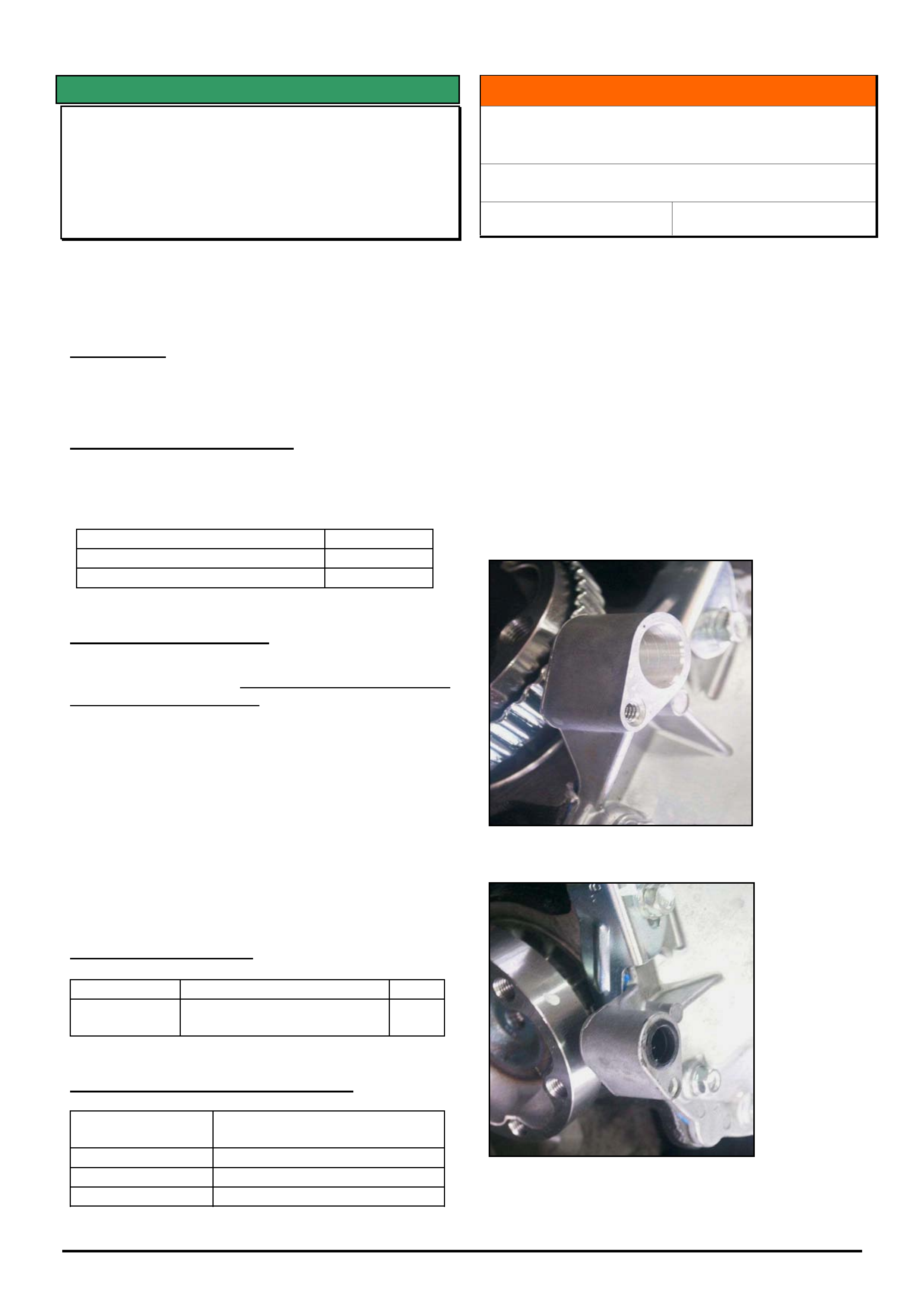
HOLDEN SERVICE TECHLINES___________________________________________________________________________DECEMBER, 2005
19
Holden Techlines are written to inform technicians of conditions that may occur on some vehicles, and to provide information that could assist in the
proper service fix of a vehicle. If a condition is described, do not assume the service fix applies to a vehicle or that the vehicle will have that condition.
SERVICE FIX
Transmission Selector Lever Loose
(Replace Pivot Pin)
VY Adventra
(GROUP 7B) TL0661A-0511
This Techline has been re-issued as there have been a
number of PIR’s mentioning this condition, where
technicians have not identified the service correction
detailed below.
CONDITION
Transmission selector lever feels loose in operation
due to the selector lever pivot pin working loose.
CORRECTION – Production
Transmission shifters with revised pivot pins (knurled)
and circlips to prevent loosening have been fitted to
vehicles from:
ISOVIN: Built Date:
LX8 - 6G1YM34F64L239771 20/02/04
CX8 - 6G1YM84F84L236786 23/02/04
CORRECTION – Service
Summary: On complaint vehicles fit a new (knurled)
pivot pin and circlip. Do NOT replace A/T Shifter
Assembly for this condition.
Caution: Existing pivot pins must NOT be deformed to
stop dislodging.
1. Remove the transmission gear selector assembly
from the vehicle as per the procedure in SIP CD.
2. Remove the existing selector pivot pin and replace
with new pivot pin and circlip as listed in Parts
Information below.
3. Reinstall all parts.
PARTS INFORMATION
Part No.: Description: Qty
92148174 Pin Kit – A/T Selector
Lever Pivot (pin & circlip)
1
WARRANTY CLAIM INFORMATION
Description Lever asm selector (auto
floor shift) - Replace
Labour Op. No. K500100
Time 0.8 hr
Failure Code K0027 Loose
INFORMATION
IRS Axle Rear Cover Plate Usage (Exchange
Axle Units or Replacement Parts)
V & W with IRS
Group 4 Ref. No. TL1057 - 0511
The following information is supplied so that Parts or
Service personnel do not attempt to exchange or re-
order parts in the belief that ‘incorrect parts’ have been
supplied.
Currently, IRS axle units are supplied with either ABS,
or non-ABS type rear covers.
In the near future, to de-proliferate the number of IRS
axle assembly covers, exchange IRS axle units will be
supplied with ABS type covers.
HSPO supplied IRS Axle assemblies and covers will
also be supplied as ‘ABS only’ style when existing
stocks of ‘Non-ABS’ parts are exhausted. The ABS
Sensor holes on non-ABS covers will be plugged as
shown below.
ABS Type Cover
Non-ABS Type Cover
(Sensor hole plugged)
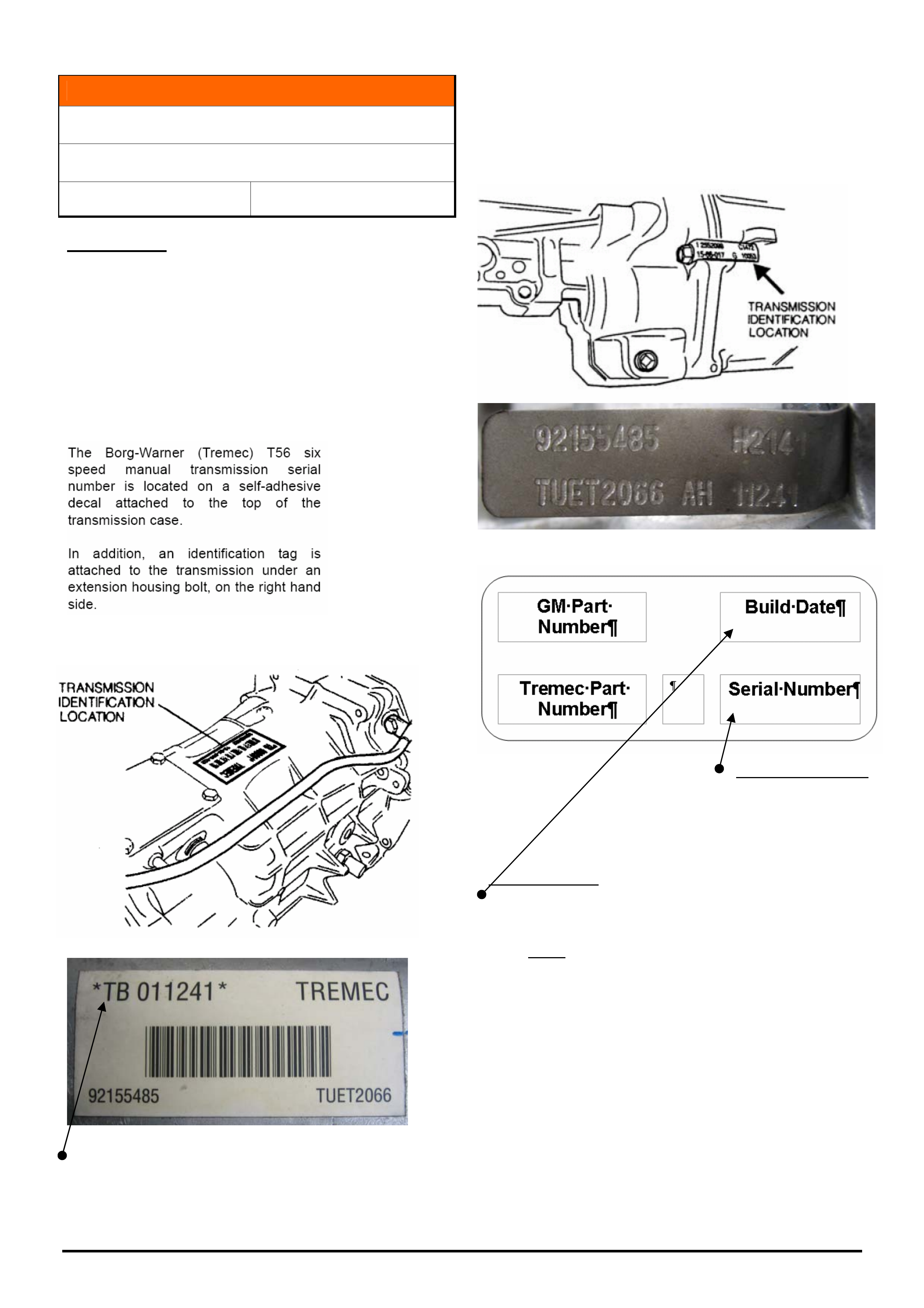
HOLDEN SERVICE TECHLINES___________________________________________________________________________DECEMBER, 2005
20
Holden Techlines are written to inform technicians of conditions that may occur on some vehicles, and to provide information that could assist in the
proper service fix of a vehicle. If a condition is described, do not assume the service fix applies to a vehicle or that the vehicle will have that condition.
INFORMATION
Tremec 6-Speed M/T Identification
V Series Gen III V8 & M/T
Group 7A Ref. No. TL1003- 0510
Background
This Techline is provided to allow technicians to define
the transmission serial numbers and date codes of
build, for Tremec 6-speed manual transmissions.
Where the Build Date & Serial No. is required - as in
the M/T Checksheet returned with any replaced M/T
assembly - the following information will assist.
These notes appear in the various Service and Parts
CD information:
The following diagrams and example photographs
allow definition of the label/tag information mentioned:
This label shows the Trans. Serial No. on the top LH
corner of the label, in the same format as it is shown in
Holden records - such as in NOW.
The serial number is shown in a different format on the
metal tag (see below).
As the metal tag format is different, the serial number
in Holden records can be obtained prior to trans
removal by searching in NOW, and is confirmed by
comparing to the serial number on the tag to the
computer record.
The above tag shows information as follows:
Bottom RH Corner:
Serial number - is shown
in a shortened format -
refer to notes on metal tag
(above). (Holden Records
will show TB011241).
Top RH Corner:
On this M/T, Build Date is “H2141”, this is deciphered
as:
H = alpha character for month = August
(Note: Letter “I” is NOT used!)
21 = 21st day of the month = 21
4 = Year
= 2004
1 = No. of shift of that day = 1st
This trans was built on 21st August, 2004 (1st shift), but
quoting the code “H2141” is sufficient for the M/T
Checksheet.
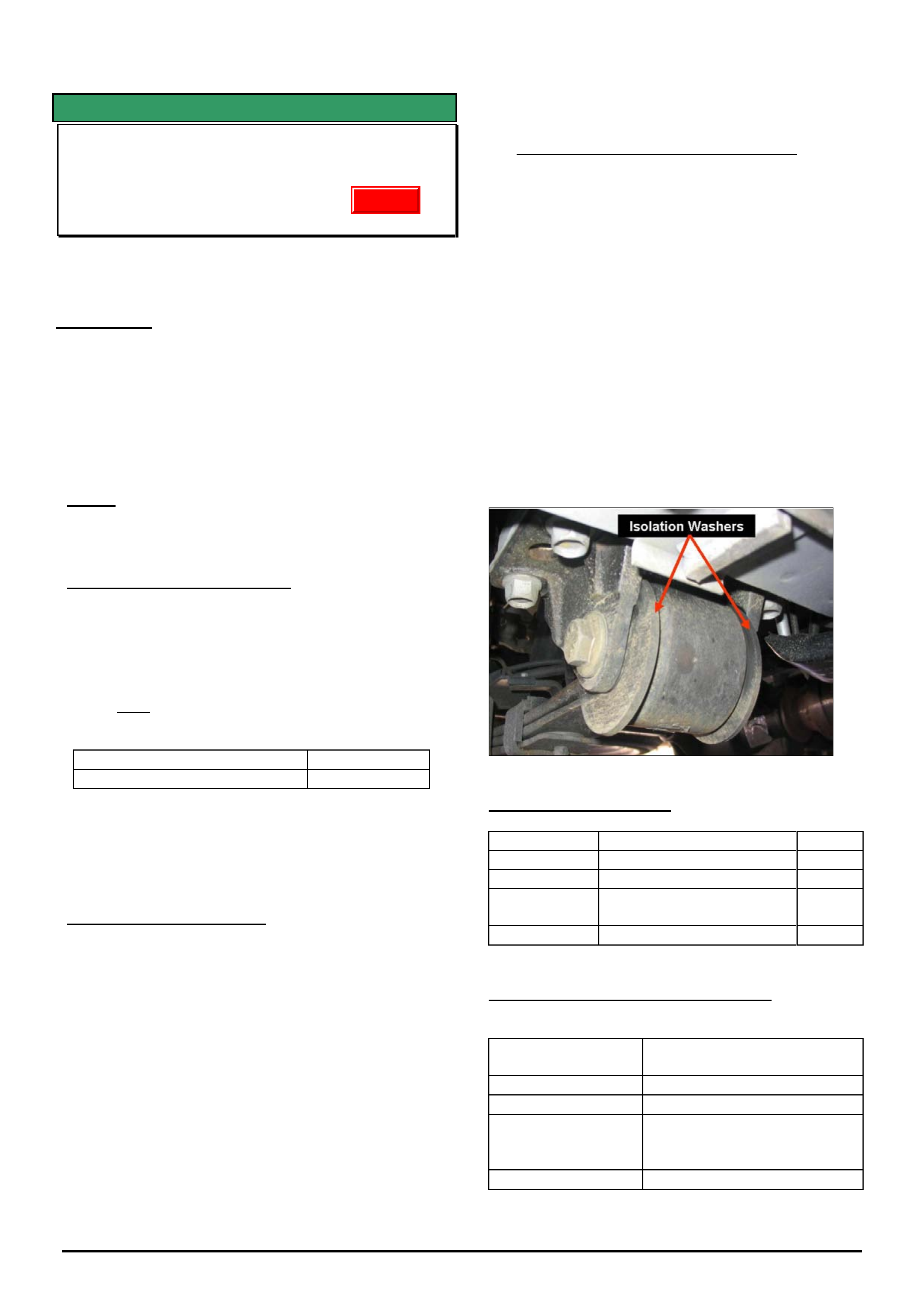
HOLDEN SERVICE TECHLINES___________________________________________________________________________DECEMBER, 2005
24
Holden Techlines are written to inform technicians of conditions that may occur on some vehicles, and to provide information that could assist in the
proper service fix of a vehicle. If a condition is described, do not assume the service fix applies to a vehicle or that the vehicle will have that condition.
SERVICE FIX
Diff. Period Whine, 80 – 110 km/hr
VY & VZ – One-Tonner & Crewman
GROUP 4 TL0631B-0511
This Techline supercedes the previous one in Issue 10, Nov.,
2004. It is revised by extending the usage of front spring eye
bushes.
CONDITION
Some vehicles may experience an unacceptable
period whine noise from the differential at
approximately 80 - 110 km/h at light to medium throttle
cruising.
A certain level of rear axle assembly noise is normal
and to be expected on these light commercial type
vehicles due to their cab chassis structure and
associated load carrying requirements.
NOTE: This noise must not be confused with noises
resulting from possible faulty differential bearings or
gears.
CORRECTION – Production
Two countermeasures introduced into production on
V8 engine vehicles are:
• A softer rubber bush in the front eye of the leaf
spring. – Crewman V8 A/T and M/T only,
• A 2-spoke pinion flange – Crewman V8 Auto
(NOT Cross-6 or Cross-8)
Breakpoint for both countermeasures in Crewman is:
ISOVIN: Built Date:
**********L218227 09/03/2004
These changes have not been introduced into other
vehicle production, but the revised spring eye bushes
may be fitted to other vehicles fitted with ‘beam’ axles
to reduce the axle noise transfer into the vehicle
passenger compartment.
CORRECTION – Service
Summary: After verifying that vehicle has condition as
described above, fit revised bushes in front eye of rear
springs of ALL vehicles. In V8 RWD (Rear Wheel
Drive) ONLY - also fit a new diff pinion flange.
Procedure. (For specific procedures not covered in detail refer
to latest PV SIP.)
1. Remove rear springs.
2. Press out existing front eye bush from each spring.
3. Press in new eye bush p/n 92148815.
4. Reinstall spring assemblies.
NOTE: There are four large washers p/n
92175916 that need to be fitted – one on each side
of the front spring eye bush as spacers/locators.
These washers are only fitted to vehicles with the
revised spring eye bushes.
5. For V8 Engine RWD vehicles ONLY: Revised
pinion flange p/n 92176653 should be fitted with a
new nut p/n 92146565 exactly as per procedure
found in PV SIP:
Section 4B – Final Drive & Drive Shafts,
2. Minor Service Operations,
2.11 Pinion Flange / Replace using old seal.
CAUTION: Overtightening of the pinion nut may
result in excessive bearing preload and bearing
damage.
6. The alternative to Dealers doing step 5 is to have a
sublet repairer (diff specialist) fit the flange.
Any such repairer must use a torque reading
tension wrench to ensure the pre-load before and
after is the same - otherwise, preload related
noise/failure may occur at a later date.
PARTS INFORMATION
Part No.: Description: Qty:
92148815 Bush Rr Spring Front 2
92175916 Washer 4
92176653 Pinion Flange (V8
ONLY)
1
92146565 Flange Nut (V8 ONLY) 1
WARRANTY CLAIM INFORMATION
All Vehicles except V8 RWD (Rear Wheel Drive):
Description Replace Bush, Leaf Spring
Front Eye – Both Sides
Labour Op. No. F000197
Time 1.6 hr.
Add for V8 (RWD
ONLY) – Fitting of
Pinion Flange
0.5 hr.
Failure Code F0040 noisy
Update