
2
20
00
05
5
S
SE
ER
RV
VI
IC
CE
E
T
TE
EC
CH
HL
LI
IN
NE
ES
S
© 2006 GM Holden Ltd. A.B.N. 84 006 893 232
Service Department
A “HOLDEN” Product.
BRISBANE SYDNEY MELBOURNE ADELAIDE PERTH
For the latest and/or any missing Techline bulletins,
please refer to Holden Lionheart
HOLDEN SERVICE TECHLINE _______________________________________________________________FEBRUARY, 2005
9
DIAGNOSIS PROCEDURE
Leak Testing Injectors in 4JX1 Engine
UBS Jackaroo & Monterey
Group 6M Ref. No. TL0832- 0501
On any engine that shows an increase of oil level, and
fuel dilution is suspected, the following procedure will
assist in identifying if leaking injectors are the cause of
this condition.
Equipment required:
1. UV Dye – e.g. SPX Multipurpose Dye, P/N 16268
2. UV light source – e.g. Kent Moore 12 Volt Leak
Detection Lamp, P/N J42220
3. Fuel safe container to mix dye and diesel.
4. Compressed air supply.
5. Pressure gauge (optional)
6. Tyre inflator.
7. Fuel pipe P/N 8971371924 or suitable banjo fitting
8. Flexible fuel hose (approx 5/16” diameter, same as
EFI pressure hose.)
9. Hose clamps (various, to suit)
10. One person brake bleeding kit - e.g. MightyVAC
Procedure:
Step 1. Remove engine tappet cover.
Step 2 – Create a fitting for the front of the fuel gallery
as follows:
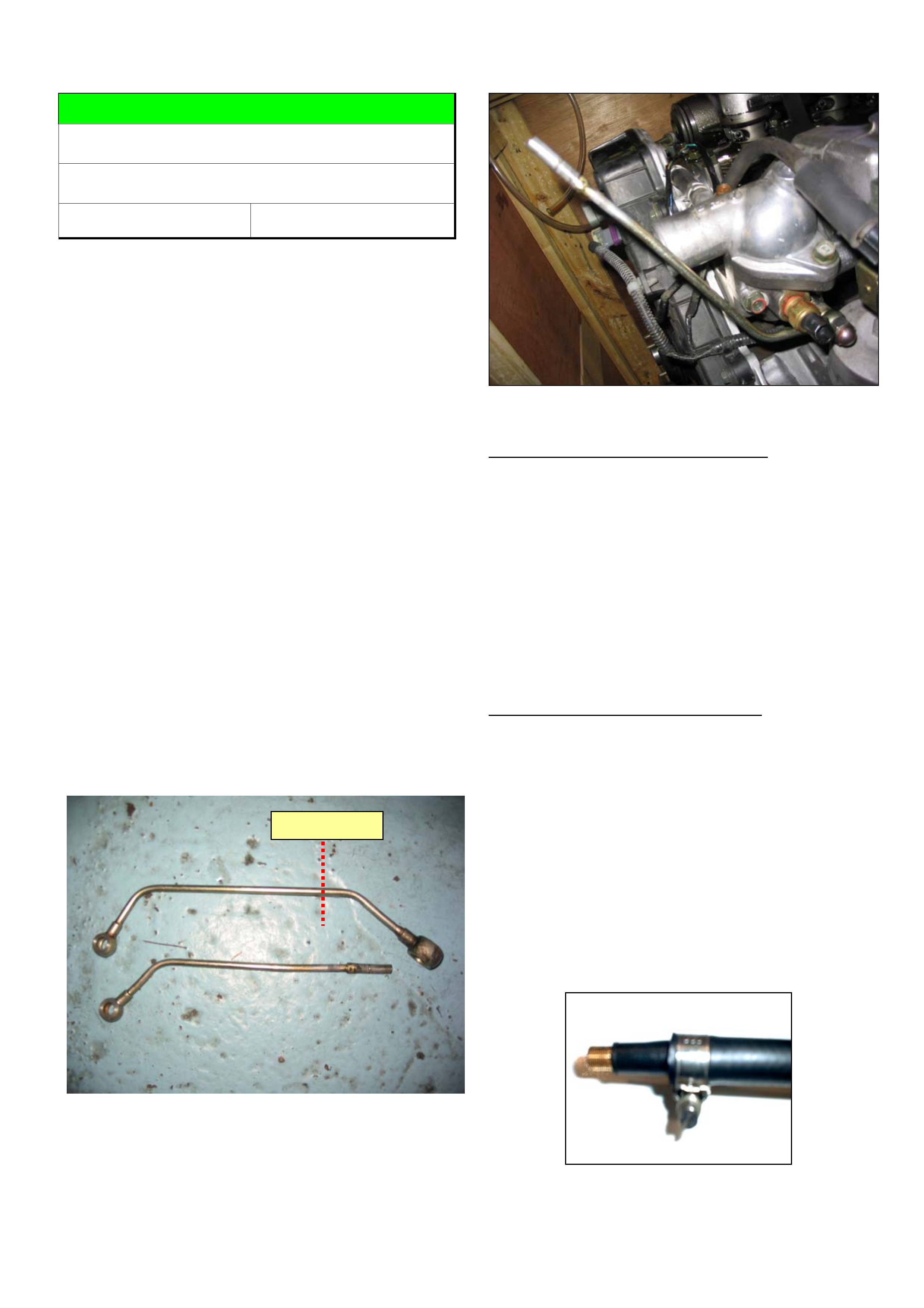
Cut the large banjo fitting from the end of the fuel pipe
(P/N 8971371924) as pictured below. The end may
need to be adapted to whatever size hose you are
using.
Figure 1. Shows fuel pipe prior to modifying
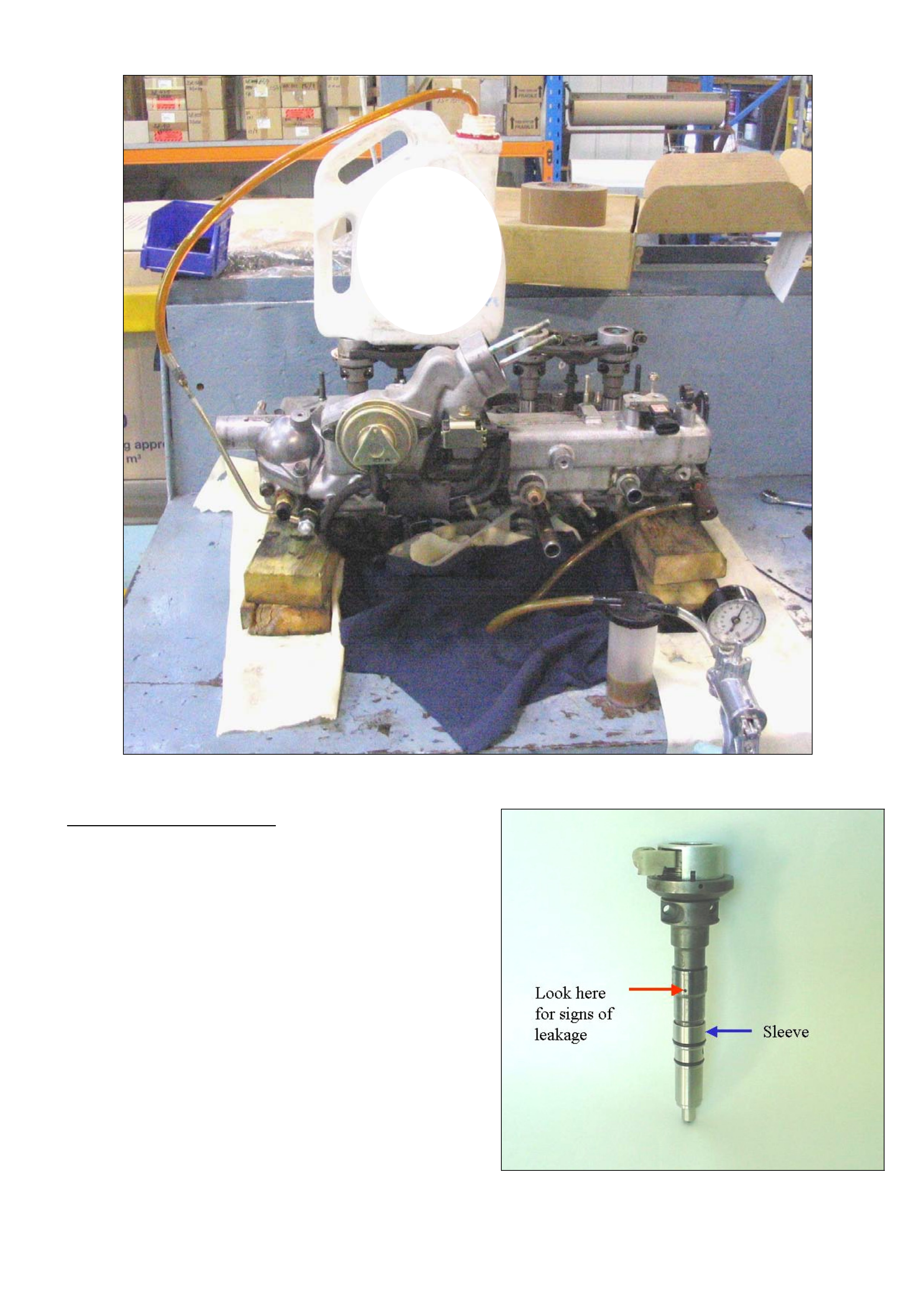
Step 3. - Remove vehicles fuel pipe (P/N
8971371924). from front of the head, then install the
modified fuel pipe or banjo fitting using the original nut
and two fibre washers. Refer Figure 2.
Figure 2.
Step 4 – Introduce fuel/dye into injectors.
Mix the dye with a suitable quantity of diesel, as per
the instructions included with the dye. Use a fuel safe
container.
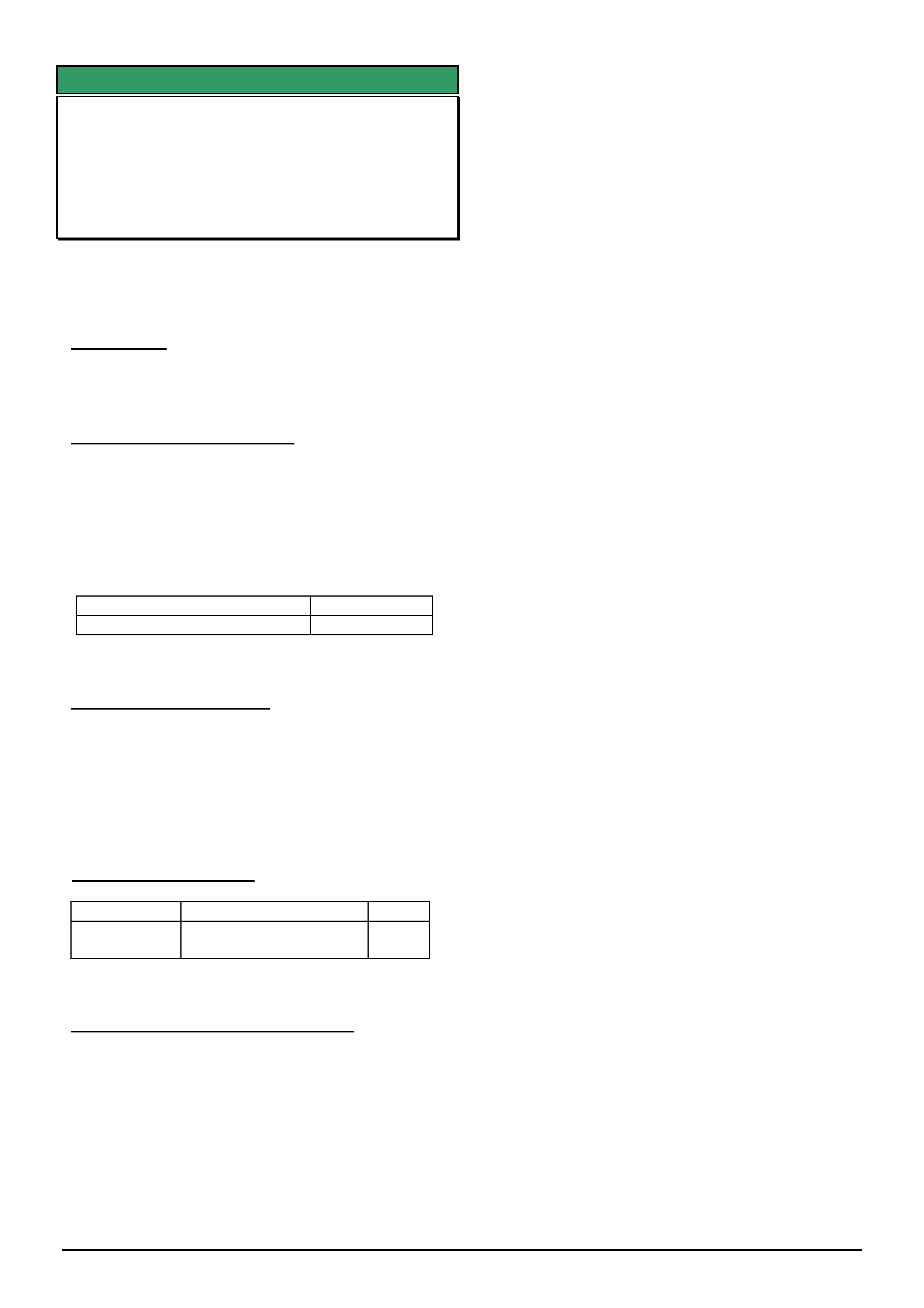
Plumb in the Mighty-VAC as shown in figure 3 (next
page). Connect a hose from the modified fuel pipe to
the container with the diesel and dye. Remove the fuel
return hose from the chassis rail and attach to the
Mighty-VAC.
Pump the Mighty-VAC steadily until the diesel / dye
mix has been pulled all the way through the fuel lines.
Step 5. Pressurise the fuel/dye mixture.
Clamp off the return line to the Mighty-VAC with
suitable pipe clamps.
Remove the Mighty-VAC.
Remove the hose from the fuel pipe on the front of the
head and attach inflator hose using hose clamp. An
inflator hose can be made by cutting the end from a
standard tubeless valve stem and inserting into 5/16”
hose. Use a hose clamp to secure valve stem. Screw a
standard Schroeder valve into valve stem. Refer to
figure 4.
Inflate fuel system to 650KPa using a tyre inflator.
Check with a gauge to make sure the pressure is
holding.
Figure 4. Inflator fitting
CUT HERE
HOLDEN SERVICE TECHLINE _______________________________________________________________FEBRUARY, 2005
10
Figure 3. Leak testing setup on bench for demonstration purposes only.
Step 6 – Inspect with UV light.
IMPORTANT: Use supplied goggles. DO NOT look
at UV light with naked eye.
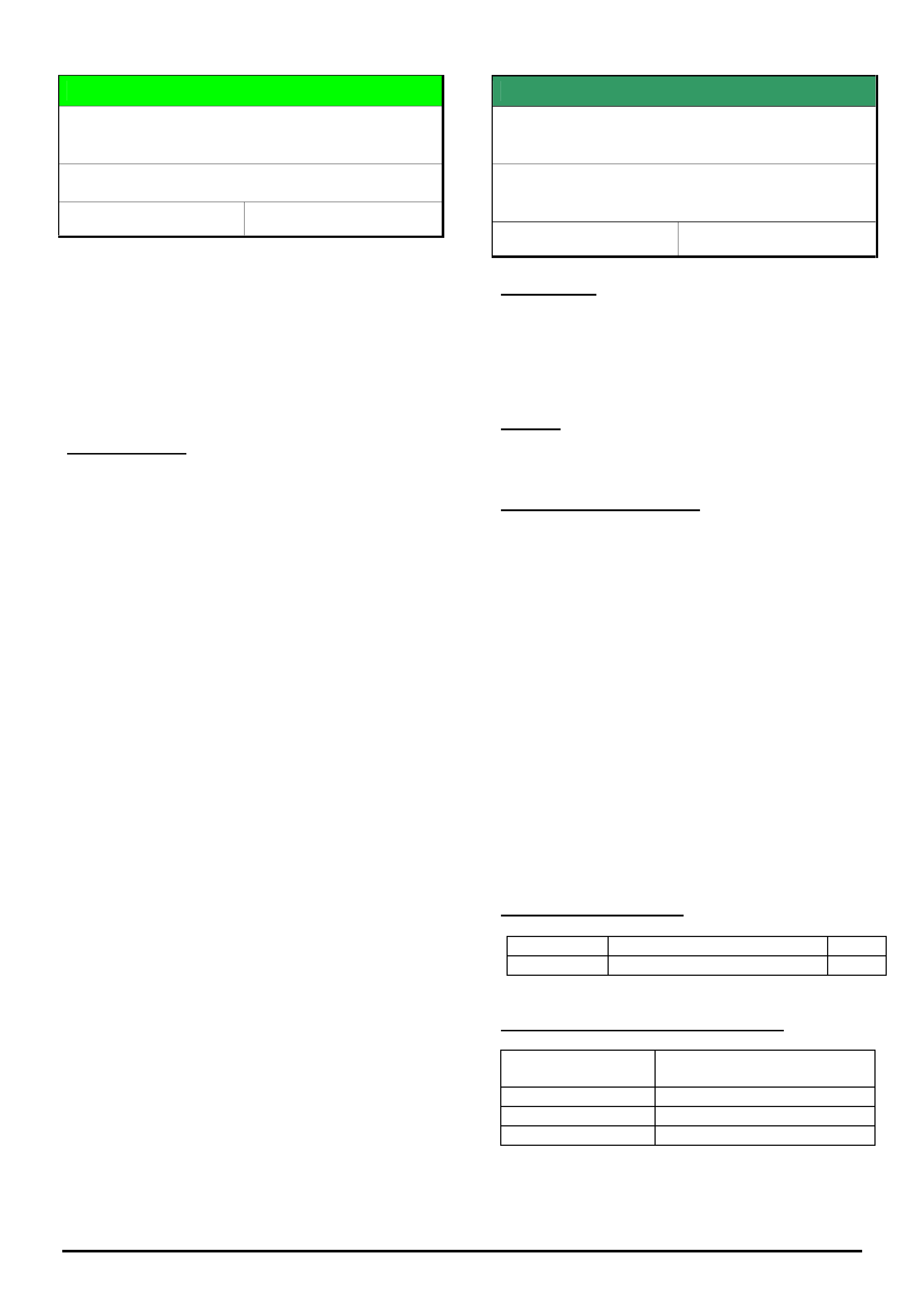
Shine the UV light around the injectors looking for
leaks. Leaks will glow a bright colour which can vary
with the type of dye used. The most common place a
leak will be found will be from the vent holes on the
sides of the injectors. Refer Figure 5. It may take 5 -
10 minutes for a leak to appear.
Note: The dye can run from the injector vent holes to
fill the area around the top of the sleeve as shown in
Figure 6. This can make it look like the sleeve o-ring
has failed. However, in all the post BP engines
recently tested in REPAC, none have had sleeve o-
ring failure.
If a leak is detected, replace injector(s) as required.
To retest the system, all the diesel and dye will have
to be flushed and cleaned from the system.
Figure 5.

HOLDEN SERVICE TECHLINE _______________________________________________________________FEBRUARY, 2005
11
Figure 6.
INFORMATION
Tech 2, TIS 2000 Model Year Selection
ALL MODELS
GROUP OB TL0852-0501
This Techline is to clarify the correct procedure for
model year selection when using Tech 2 or TIS 2000.
For many programming operations and diagnostics
carried out using Tech 2 and TIS 2000 it is critical
that the correct model year is selected. This can be
easily identified by the tenth character of the VIN.
The screen below is an example of the Tech 2 Model
Year selection screen. The Numbers and letters on
the LH side in brackets are the values of the tenth
digit of the VIN for that model Year.

HOLDEN SERVICE TECHLINE _______________________________________________________________FEBRUARY, 2005
13
DIAGNOSIS HINT
Fluid Leak Diagnosis Using Black Light And Dye
All Models
Group: OB Ref. No. TL0837- 0501
This techline is repeated from year 2000 techlines.
The information provided in this techline is to assist Dealers in performing thorough and accurate diagnosis of
fluid leaks prior to commencing any rectification work or removing major components.
Components must NOT be replaced for “leaks” without thorough definition of leak sources.
Use of Black Light Dye and Black Light is highly recommended to trace leak sources. For extensive information
on the use of Black Light and Black Light Dye, refer to the following information repeated from a previous All
Dealer Letter.
Holden strongly recommends the use of the black light and dye method to diagnose fluid leak sources. This
method of leak detection is a proven, reliable method that identifies the specific leak source and/or location.
The black light and dye method can be used for various types of leak detection, when used with the appropriate
tracer dye it can be used for detecting engine and transmission fluid leaks, Refrigerant leaks, fuel leaks, and
coolant leaks.
The following pages provide answers to technicians’ questions about the various aspects of black light and
tracer dye, and how dealerships may use this tool to their advantage.
Black Light & Tracer Dye and Accessories
There are different types of tracer dye for different applications, plus for air-conditioning systems, an
injector is required to infuse the dye into the system. The following tracer dyes and accessories are
available from SPx Australia. Other equivalent products may be used in their place.
Contact details for SPx Australia – Ph.: (03) 9544 6222; Fax: (03) 9544 5222.
Application Part Number
Black Light Leak Detection
Lamp
16296
Replacement Black Light Bulb
AU 512
R134a Air Conditioning Tracer
Dye
(24 X 8ml bottles)
J41447
R12 Air Conditioning Tracer
Dye
(24 X 8ml bottles)
J39475
R134a Air Conditioning Injector
J41459
R12 Air Conditioning Injector
J41709
Petrol & Diesel Engine Fluid and
Transmission Fluid Tracer Dye
(24 X 1 oz bottles)
J28431-B
Coolant Tracer Dye
(24 X 1 oz bottles)
J29545-6A
Multi purpose dye
(engine oil, transmission & power
steering fluid, diesel & petrol)
16268

HOLDEN SERVICE TECHLINE _______________________________________________________________FEBRUARY, 2005
14
Black Light & Tracer Dye Useage Information
The following pages will answer most questions you may have about using Black Light and Tracer Dye.
Summary of the steps involved in detecting a fluid leak using black light and dye:
Pour specified amount of dye into the system.
Road test the vehicle under normal operating conditions, to allow the dye to mix with the host fluid/gas.
Define the leak source by directing the Black Light towards the suspect area. The fluid leak will appear as a
brightly coloured path leading to the source. Note: The colour of the dyed fluid can be checked on the dipstick,
or other component directly in contact with the host fluid/gas.
Repair fluid leak cause and recheck to ensure that leak has been rectified.
General Information
How much dye do you use? The following information is given as a guide only. Always refer to the label on the
bottle.
Engine, Transmission, Fuel
J28431-B Engine & Trans. Fluid Dye should be used as follows:
Petrol Engine Oil - 7.4ml per 3.79litres of oil (¼oz per 4-5 quarts)
Diesel Engine Oil - 7.4ml per 3.78litres of oil (¼oz per 4 quarts)
Automatic Trans. Fluid - 14.8ml per 5.68litres of fluid (2x¼oz per 6 quarts)
Manual Trans. Fluid/Oil - 7.4ml per 5.68litres of fluid (¼oz per 6 quarts)
Petrol or Diesel Fuel - 7.4ml per 7.57litres of fuel (¼oz per 2 gallons)
A/C Systems
J41447 R134a A/C Dye should be used as follows:
R134a A/C System - 7.4ml per A/C system (¼oz per system)
J39475 R12 A/C Dye should be used as follows:
R12 A/C System - 7.4ml per A/C system (¼oz per system)
Power Steering
J28431-B Engine & Trans. Fluid Dye can be used in Power Steering as follows:
Power Steering Fluid - 7.4ml per 5.68litres of fluid (¼oz per 6 quarts)
Engine Coolant Systems
J29545-6A Coolant Dye should be used as follows:
Coolant System Radiator Fluid - 7.4ml per 15.14 litres (¼oz per 16 quarts)
Note: These amounts are based on various tests - there may be occasions when good fluorescence is not
obtained with these amounts of dye, due to the condition of the host oil/fluid or the nature of certain additive
packages in the oil/fluid itself. If this occurs, use additional dye.

HOLDEN SERVICE TECHLINE _______________________________________________________________FEBRUARY, 2005
15
Q A
Do you need to use the
Fluorescent Enhancer Safety
Goggles?
Yes - they not only protect the technician, but also visually optimise the
dye fluorescence for enhanced leak detection. They are scientifically
designed to enhance fluorescence by eliminating light at wave lengths
that might interfere with the eye’s ability to view the dye’s fluorescent
light emission. Once you look at the dye with and without the goggles,
you will see the difference.
What life does the dye have
when left in coolant, ATF,
R12 and R134a refrigerant?
Indefinite - unless the ATF is “burnt” in an A/T clutch failure or if here is
an A/C compressor failure.
What life does the dye have
when left in engine oil?
Depends on how dirty the oil was when the dye was added. In clean petrol
engine oil, it will last 500+km. In diesel engine oil, it will not last as long
because of rapid carbon build-up.
Are there any adverse effects
of leaving dye in systems too
long?
None - and A/C dyes especially are very thermally stable and should last
100,000 km.
Is there a preferred method
of cleaning the dye from a
vehicle, if spilt?
IMPORTANT - Do NOT get dyes on any painted surfaces - use guard
covers when pouring dyes into any vehicle system or injecting A/C dyes. A
good cleaning solvent should clean any dye off any metal surfaces. A/C
dyes cannot be cleaned off hoses or plastic components.
What is the shelf life of the
dyes?
Indefinite, but it is recommended they be used within five years.
PETROL & DIESEL ENGINE & TRANSMISSION OIL LEAKS
Use J28431-B dye in quantities as specified in “General Information” section.
Putting dye into oil that is fairly clean will achieve the best fluorescence for le ak inspection because the greater
the carbon build-up in the oil, the more difficult to obtain good fluorescence from the dye. Therefore, if the oil
appears to be extremely dirty on the dipstick, additional dye may be required to obtain good fluorescence and
can be added without harm to the engine.
Q A
How do I know if the dilution
ratio of dye added is correct?
After adding dye at the recommended dilution ratio, operate the engine 3 to
5 minutes to allow dye to mix with oil. Then check the oil dipstick with
black light for the yellow-green fluorescent glow of the oil/dye mixture.
What is the proper procedure
for adding dye to the engine?
With the engine OFF. This will prevent possible splashing of the dye over
an area of the engine that may need inspecting.
How long does it normally
take for the dye to work?
Most leaks will appear after operating the engine 5 to 10 minutes. However,
it is recommended that the vehicle be taken for a short road test in order to
allow the dye to penetrate all leaks.
How long will it take for the
dye to penetrate very small
pinholes or porosity leaks?
To accurately detect leaks of this type, the vehicle should be operated for 1
to 3 hours under normal operating conditions. Suggestion: If such a leak is
suspected, add dye to the engine oil. Then have the vehicle owner use the
vehicle for the time recommended above. The owner should then return for
leak inspection with the black light.
Do I have to clean engine NO! Under black light, all petroleum-based products such as oil, grease, and

HOLDEN SERVICE TECHLINE _______________________________________________________________FEBRUARY, 2005
16
Q A
surfaces prior to using the
dye?
ATF will fluoresce blue. The dye will penetrate surface oil, grease and grit
to leave a yellow-green fluorescent trace (under black light) at the source of
the leak.
Do I have to clean the engine
after repairing the leak?
YES! But only at the source of the leak in order to allow the technician to
operate the engine and then re-inspect the leak repair to insure the job was
done right the first time. Suggestion: The dye/oil mixture can be removed
by using any engine degreaser or solvent-type shop cleaner.
After adding dye to the
engine oil, is it necessary to
change the oil prior to
returning the vehicle to the
customer?
NO! The dye is 100% compatible with engine oil and can remain in the
system without harm until the next oil change.
How long will it take for
ATF dye to work?
Most leaks will appear after operating the transmission for 5 to 10 minutes.
However, it is recommended that the vehicle be taken for a short road test in
order to allow ATF dye to penetrate all leaks. NOTE: All other application
and leak-detection procedures remain the same as given under the Engine
Dye Section (above). It is not necessary to clean transmission exterior
surfaces prior to using ATF dye. To detect small pinhole or porosity leaks,
the vehicle should be operated for 1 to 3 hours. The ATF dye mixture
should be cleaned from the source of the leak, and it is not necessary to
change ATF after adding dye.
How long will ATF dye be
effective in the transmission?
Because the transmission remains fairly clean internally and does not have
the carbon build-up problem present in petrol and diesel engines, the ATF
dye will be effective as long as the ATF is not changed or the ATF is not
“burnt” or discoloured by a transmission failure. Remember to check the
dipstick with the black light prior to inspecting for leaks to check
fluorescence, and do not forget to check the ATF cooler line for leaks.
BRAKE SYSTEM LEAKS
Q A
Can I use a fluorescent dye
in a brake system?
Never use any type of a fluorescent tracer dye in a brake system.
POWER STEERING LEAKS
Q A
How much dye should I use
for finding power steering
leaks?
Check the fluid capacity of the power steering system. You will probably
need to add only a small amount of dye at a dilution ratio of 7.4ml (¼ oz) to
5.68l (6 quarts) of power steering fluid. Run the system, then check the cap
or dipstick for fluorescence with the black light.

HOLDEN SERVICE TECHLINE _______________________________________________________________FEBRUARY, 2005
17
FUEL SYSTEM LEAKS
When a fuel system leak is suspected, it is recommended that the vehicle being tested have a quarter tank or less
of fuel. Trucks and larger capacity systems should be estimated as close as possible in order to keep the dye
requirement at a minimum and to keep the test procedure as economical as possible. If a difficult leak is
suspected, adding more dye than normal (a higher concentration) will produce the best results and will not harm
the system.
Q A
How do I know if enough
fuel dye has been added?
Any dipstick device that can be inserted into the filler tube can be used and
then inspected for fluorescence with the black light.
On a fuel-injected (PFI)
vehicle, can I use the fuel
rail for injecting dye?
NO! The small volume of petrol that will receive the dye is probably
insufficient for the dye to show up at an “O” ring injector leak for example.
COOLANT SYSTEM LEAKS
Q A
What is the proper procedure
for adding dye to the cooling
system?
Add dye with the engine off and radiator “cold”. This will prevent splashing
of dye and possible false readings. Also, add the coolant dye directly into
radiator and not into the reserve/surge tank found on some vehicles.
How do I clean the coolant
with dye off the radiator and
engine surfaces?
Use water with detergent and a small scrub brush.
How can I check for a
suspected coolant leak into
the engine oil?
Perform test as follows:-
Pull the engine oil dipstick and confirm the blue fluorescence of the engine
oil with the black light. (This is oil to which no dye has been added.)
With the engine off and the radiator cold, pour coolant dye into the radiator,
and operate vehicle for at least one day to allow coolant to leak into engine
oil.
With the engine off, pull engine oil dipstick and fluoresce dipstick with
black light.
If coolant is leaking into the engine oil, the dipstick should show some green
fluorescent droplets of coolant. Also, the engine oil might fluoresce a slight
whitish blue colour instead of the normal strong blue fluorescence of engine
oil.

HOLDEN SERVICE TECHLINE _______________________________________________________________FEBRUARY, 2005
18
USING DYE IN R134a or R12 A/C SYSTEMS
When dye is injected into an A/C system and the system has been operated under full pressure for 5 to 10
minutes, the dye will remain in the system even though the R134a or R12 has been evacuated for a repair. The
only time R134a or R12 dye must be replenished is when the A/C system is flushed of refrigerant oil.
Q A
How do I put R134a or R12
dye into an automotive car or
truck A/C system?
Put 7.4ml (¼ oz) of dye in the dye injector reservoir, and use a refrigerant
source to inject the dye into the A/C system.
How long will it take the
R134a or R12 dye to circulate
through the typical
automotive A/C system?
Operating the A/C system under full pressure, it will take the dye
approximately 5 to 10 minutes to circulate through most A/C systems.
However, this does not mean that the A/C leak will show up in that time
period.
How long after putting
R134a or R12 dye into the
A/C system and running the
system under full pressure
can I begin looking for the
A/C leak with the black light?
This depends on the size and location of the leak. As the refrigerant escapes
under pressure, it carries with it a very small amount of refrigerant lubricant.
This trace of lubricant is what you are looking for with the black light.
Therefore, the size of the leak will determine how long it takes for the
lubricant dye to appear and fluoresce under the black light. A hose porosity
leak would, therefore, take longer to appear than a fracture/fitting leak.
Example: A high-pressure side leak may take over a week or more to have
enough refrigerant escape to affect the cooling capacity of the A/C system,
return the car to the customer, and tell them to bring it back for leak
inspection when they again notice a lack of cooling by the A/C system. When
this car returns, the refrigerant that has escaped will leave a trace of
refrigerant lubricant with dye, which is what you will be looking for with the
black light.
How do I know if I have a
leaky service valve on the
low-pressure side if I just
used that valve to put dye into
the A/C system?
After putting the R134a or R12 dye into the A/C system through the low-
pressure service valve, clean the valve with a solvent if the refrigerant taking
the dye into the A/C system did not clean off the service valve, sufficiently to
remove all trace of dye. Do this before starting the A/C system.
How do I clean the R134a or
R12 dye off A/C components
and engine surfaces?
Use any shop degreaser or solvent to clean dye off A/C components or
engine surfaces.
Are these A/C dyes
compatible with my
refrigerant recovery and
recycle equipment?
These dyes have been tested and proven compatible by major manufacturers
of recovery and recycle equipment. When refrigerant is evacuated from an
A/C system, a small amount of compressor lubricant is also removed from
the system. The R134a or R12 dye is in solution with the system compressor
lubricant, therefore, is separated in the recovery/recycle unit along with the
compressor lubricant. Because of the small amount of compressor lubricant
removed by the recovery/recycle unit, there is no need to add additional R-
134a or R-12 dye to the A/C system for future leak detection.
How do I know if a vehicle’s
A/C system contains dye?
Remove the low-side service port sealing cap and direct the black lamp into
the valve stem area. If you do not see dye/lubricant in this area, depress the
valve stem only for an instant to help bring out some lubricant with the
refrigerant. Again direct the black light at the valve stem for traces of the
fluorescent dye/lubricant. Clean dye off service port.

HOLDEN SERVICE TECHLINE _______________________________________________________________FEBRUARY, 2005
19
Q A
How do I check for
refrigerant leaks in the
evaporator when I cannot use
the black light to see the
leak?
Use the black light to fluoresce the drain hole and see if a trace of the yellow
green dyes has washed down with the condensation. When the evaporator is
removed from the vehicle, use the black light to determine the exact location
of the leak on the evaporator. Remember to check the fittings to and from the
evaporator to be sure they are not the cause of the leak.
How do I check for the
dye/lubricant when I cannot
directly shine the black light
on all suspected leak areas?
Use a mirror to reflect the black light to the underside of a fitting, hose or
component. Also if a mirror cannot be used, a white cloth can be used to
wipe the suspected area, and then fluoresce the cloth with the black light to
check for traces of the yellow-green dye.
Can the dyes remain in the
A/C system after it has been
used for the initial leak
detection?
Dyes can safely and effectively remain in the A/C system after the initial
repair. Dyes can be used to detect future refrigerant leaks and can only be
removed from the A/C system by flushing out the system compressor
lubricant.

HOLDEN SERVICE TECHLINE _______________________________________________________________FEBRUARY, 2005
20
INFORMATION
Holden Contacts and procedures
All Models
Group OB Ref. No. TL0679A- 0501
This Techline supercedes the previous one in Issue
3, April 2004. Revisions are shown in red.
This techline summarises some of the Holden
contact procedures and gives a quick reference
guide for contact numbers.
Security information.
To obtain security information for both Passenger
and LCRV vehicles the first step is to check
Lionheart. If the information is unavailable on
Lionheart then a completed security information
request form must be faxed through to the security
information department, as security information
cannot be given out by phone. Please note that
security information requests are processed by the
security information department and not TAS.
Please ensure you have the latest security
information request form, which is available on
Passenger Vehicle SIP for both Passenger and
LCRV. Contact details are listed below. There can be
up to a 4-hour turn around on requests however if the
information needs to be obtained from overseas, it
may take up to 24 hrs. Do not phone the security
information department unless you have not received
a response in the normal turn around time. For
further information please refer to ADL 63/99.
Parts inquiries and information
If any information or assistance is required in regards
to part numbers or Partfinder, please refer to the
Holden Help section in Partfinder.
Warranty Authorisation and enquiries
Warranty can only be authorised by your Aftersales
District Manager. Labour times information is
available on SIP or from the warranty department.
For any other warranty inquiries please contact
Warranty Administration.
TAS
Technical Assistance Service (TAS) is a service
provided by Holden to assist Holden Dealers in
problem resolution.
Contact to TAS must be made by a Nominated
Contact as outlined in Section 5 of the TAS
procedures manual. All techlines, dealer letters and
service information must be checked prior to
contacting TAS. The Nominated Contact must not
contact TAS until he/she has been fully involved with
the faulting vehicle and all Dealer expertise has been
exhausted. Problems should be escalated through
the Dealership to the senior technician/foreman
before contacting TAS.
TAS cases must be updated or closed within 30 days
unless a Dealer is waiting on a service fix to be
provided. It is the Dealers responsibility to update
cases. All cases should be recorded in the TAS
procedures manual, which should be referred to prior
to contacting TAS. Please note that an electronic
copy of the TAS procedures manual is also available
on passenger SIP.
All Daewoo TAS enquiries must be done by Fax.
Under no circumstances should you call TAS for
Daewoo enquiries.
Under no circumstances are TAS or other Holden
contact details to be supplied to customers or
independent repairers. TAS is a service restricted to
assisting Holden Dealer service departments.
Quick reference contact numbers
Air International Ph 1800 673 716
Australian Arrow Ph 03 9785 0792
Blaupunkt Ph 1300 307 036
Bosch Technical Assistance Ph 1800 025 462
Clarion Ph 1300 730 730
Fax 03 9551 0377
Customer Assistance Ph 1800 033 349
Dana Ph 02 9892 9237
Fax 02 9892 9310
www.spiceraxle.com.au
Delphi Ph 1800 335 777
Eurovox Ph 03 9237 0800
Fujitsu Ten Ph 03 9646 6008
Holden Assist Ph 1300 880 088
HSV Ph 03 9265 9500
Infomedia (SIP, Partfinder) Ph 1800 810 103
Panasonic Ph 02 9986 7635
PBR Diagnostic assistance Ph 1800 468 727
Petro-Ject Ph 02 9890 5701
Ph 02 9890 5244
Philips/Siemens-VDO Ph 1800 335 282
Salmat Ph 03 9358
2900
Security Information Ph 03 9647 2001
Fax 03 9647 2865
SPX Australia Ph 03 9544 6222
TAS Ph 1800 033 417
Fax 03 9647 2495
Email [email protected]
Warranty Ph 1800 033 487
Update
HOLDEN SERVICE TECHLINE ________________________________________________________________________________MARCH, 2005
12
Holden Techlines are written to inform technicians of conditions that may occur on some vehicles, and to provide information that could assist in the
proper service fix of a vehicle. If a condition is described, do not assume the service fix applies to a vehicle or that the vehicle will have that condition.
SERVICE FIX
Manual Transmission Front Countershaft
Roller Bearing Noisy
RA Rodeo with M/T
(GROUP 7A) TL0683A-0502
This Techline supercedes the previous one in Issue 5,
June,2004. It is revised by correcting the Production
Breakpoint Information. (Shown in red)
CONDITION
Transmission countershaft bearing noise evident due
to premature failure of front countershaft roller bearing.
CORRECTION – Production
Revised design (wider) front countershaft roller
bearings have been fitted to all transmissions from
Trans Serial No. 38215353 (Date 21/8/2003)
Transmissions with revised design (wider) front
countershaft roller bearings have been fitted to
vehicles from:
ISOVIN: Built Date:
MPATFR26J4H510242 30/9/2003
CORRECTION – Service
Where evaluation of the complaint noise is consistent
with a countershaft bearing noise (evident in all
forward gears except 4th) inspect the front countershaft
roller bearing for signs of wear. Fit a new bearing as
required, as per the procedure outlined in Light
Commercial SIP CD.
PARTS INFORMATION
Part No.: Description: Qty:
8970296004 Bearing Roller
Countershaft Front
1
WARRANTY CLAIM INFORMATION
Use Labour Times information in Warranty Information
section of current Passenger Vehicle SIP CD

HOLDEN SERVICE TECHLINE ________________________________________________________________________________MARCH, 2005
14
Holden Techlines are written to inform technicians of conditions that may occur on some vehicles, and to provide information that could assist in the
DIAGNOSIS HINT
Engine Surge or Low Power After Engine
or Gearbox Repair
RA Rodeo 3.5 L 6VE1
Group 6C Ref. No. TL0873- 0502
PROBLEM DESCRIPTION
Vehicle may surge or flat spot when under partial load
(E.G. half acceleration). Vehicle will perform normally
when accelerator is pressed to wide open position.
The problem usually occurs after repairs that have
required the engine or gearbox to be removed from
the vehicle.
Fault codes related to rich or lean condition MAY be
logged in ECU
SERVICE RECTIFICATION
Check O2 sensor operation with Tech 2; Check short
term and long term fuel trims, to see if there is a big
variance from Bank 1 to Bank 2 .
E.G. (Bank 1 STFT –30% Bank 2 STFT +30 %)
If there is a large variation, the problem is most likely
due to the O2 sensor wires having been crossed from
side to side when the wiring has been refitted.
In this case, check the correct O2 sensors are
connected to the correct plug. If a problem is found,
correct the wiring and clear fuel trim cells with Tech 2
and retest vehicle operation.
INFORMATION
Release of Dexron III (“H” Revision)
Automatic Transmission Fluid (ATF)
All models with A/T
Group 7B Ref. No. TL0860- 0502
General Motors DEXRON III ATF specification has
been upgraded to DEXRON III (H-Revision).
Commercially available fluids labelled as “DEXRON III,
Approved for the H Specification”, can be used in any
transmission application which specifies the use of
DEXRON III, IIE, II or DEXRON.
Current stock of DEXRON III ATF can be used until
the supply is depleted.

HOLDEN SERVICE TECHLINE ________________________________________________________________________________MARCH, 2005
16
Holden Techlines are written to inform technicians of conditions that may occur on some vehicles, and to provide information that could assist in the
proper service fix of a vehicle. If a condition is described, do not assume the service fix applies to a vehicle or that the vehicle will have that condition.
INFORMATION
Finding D.T.C’s on LCV SIP
All LCV Models
Group OB Ref. No. TL0874- 0502
The Light Commercial Vehicle (LCV) group in TAS
receives many calls from Dealers unable to locate
Diagnostic Trouble Code (D.T.C.) information for
LCV models.
The following instructions provide a step by step
procedure for locating this information.
ALL MODELS except YG Cruze
1. Open L.C.V. S.I.P. program from Desktop (double
click icon).
2. Select “Service Information” (single click)
3. Select Vehicle type eg., RA Rodeo, UE Frontera,
UBS Jackaroo (single click)
4. Select Engine type fitted to the vehicle and “single
click” “+” to expand menu.
5. From the selections available, select the title with
the words “Engine Driveability and
Emissions”(or similar)
6. From the list of topics under “Engine Driveability
and Emissions” look for the title “ECM Diagnostic
Trouble codes” or “PCM Diagnostic Trouble
Codes”. The DTC’s are contained in these
sections.
NOTE: In some instances, the DTCs will also
appear in the menu of topics on the LHS of the
screen.
YG Cruze
1. Open L.C.V. SIP program from Desktop (double
click icon).
2. Select YG Cruze (single click)
3. Expand “Engine” as mentioned above.
4. Select Section 6 Engine General Information
5. Open Section 2 Engine Diagnosis
6. DTC information starts at Section 2.13

HOLDEN SERVICE TECHLINE ________________________________________________________________________________APRIL, 2005
8
Holden Techlines are written to inform technicians of conditions that may occur on some vehicles, and to provide information that could assist in the
proper service fix of a vehicle. If a condition is described, do not assume the service fix applies to a vehicle or that the vehicle will have that condition.
INFORMATION
TIS 2000 Security Access and SPS Issues Due
To Hardware Key Incompatibility With New PC
All Models
Group OB Ref. No. TL0896- 0503
CONDITION
After installation of a new PC, Dealers may report
problems accessing security information or service
programming system (SPS). An error message may
appear. The problem may be intermittent.
CAUSE
New PC’s with a processor speed which is 2.0 Ghz or
greater are not compatible with older style “dongle”
hardware keys.
CORRECTION
To overcome this, a new “superpro” hardware key kit
(Parallel or USB) will need to be purchased through
SPX.
Please note: New hardware keys will need to be
registered before they will work.
The above information was explained in All Dealer
Letter 14/04
INFORMATION
Tis 2000 and Tech 2 ECU Programming
Terminology
GROUP OB TL0902-0503
When trying to reset or program modules with TIS
2000 or Tech 2, “reset ECU” or “program ECU” is often
displayed. Many Dealers assume ECU stands for
Engine Control Unit. This techline is to clarify that
ECU stands for “Electronic control unit” not “engine
control unit” and therefore applies to the module you
are dealing with.
For example - If you are resetting a CIM and tech 2
displays “reset ECU” it is referring to the CIM because
that is the module you are resetting and have
accessed with tech 2.
HOLDEN SERVICE TECHLINE ________________________________________________________________________________APRIL, 2005
10
Holden Techlines are written to inform technicians of conditions that may occur on some vehicles, and to provide information that could assist in the
proper service fix of a vehicle. If a condition is described, do not assume the service fix applies to a vehicle or that the vehicle will have that condition.
DIAGNOSIS HINT
First Steps In Electrical Problem Diagnosis
(Check Earth Points)
RA Rodeo (and other models)
Group 12 Ref. No. TL0892- 0503
TAS receives numerous calls on varying Electrical
faults on the above models.
Some of these are DTC’s and SPS related problems.
A potential cause of these problems could be poor
electrical contact at Earth points. e.g. loose
attachments, dirt or paint between Terminal and
body.
SERVICE HINT
Prior to contacting TAS for help with diagnosis of any
electrical fault, it is strongly recommended that you
check/clean all the Earth points first.
The Earth Points in LCV SIP are located by the
following path:
Service Information/ RA / Engine type / 6E - “Engine
driveability and emissions” / Ground Point Chart /
Location.
This leads to photographs showing the exact location
of earth points.
If, after checking/cleaning earth points, the problem
is still present, contact TAS using the standard
procedure.
SERVICE FIX
Accelerator sensitivity at slow speeds and
over rough terrain.
RA Rodeo 4JH1-TC Diesel with Manual
transmission
Group 6C Ref. No. TL0865- 0503
CONDITION
Some owners may complain that the vehicle throttle
control is too sensitive. When driven at slow speed
or on rough terrain with low range or a low gear
selected, this sensitivity can create a jerking or
hopping motion.
CAUSE
Insufficient resistance in accelerator system.
CORRECTION – Service
(1) Adjust the throttle position sensor so that the
throttle position % (on Tech II) begins to increase
from 0 % as soon as the throttle butterfly starts to
move from the idle position.
Note: The throttle position sensor must still read 0%
when the vehicle is at idle.
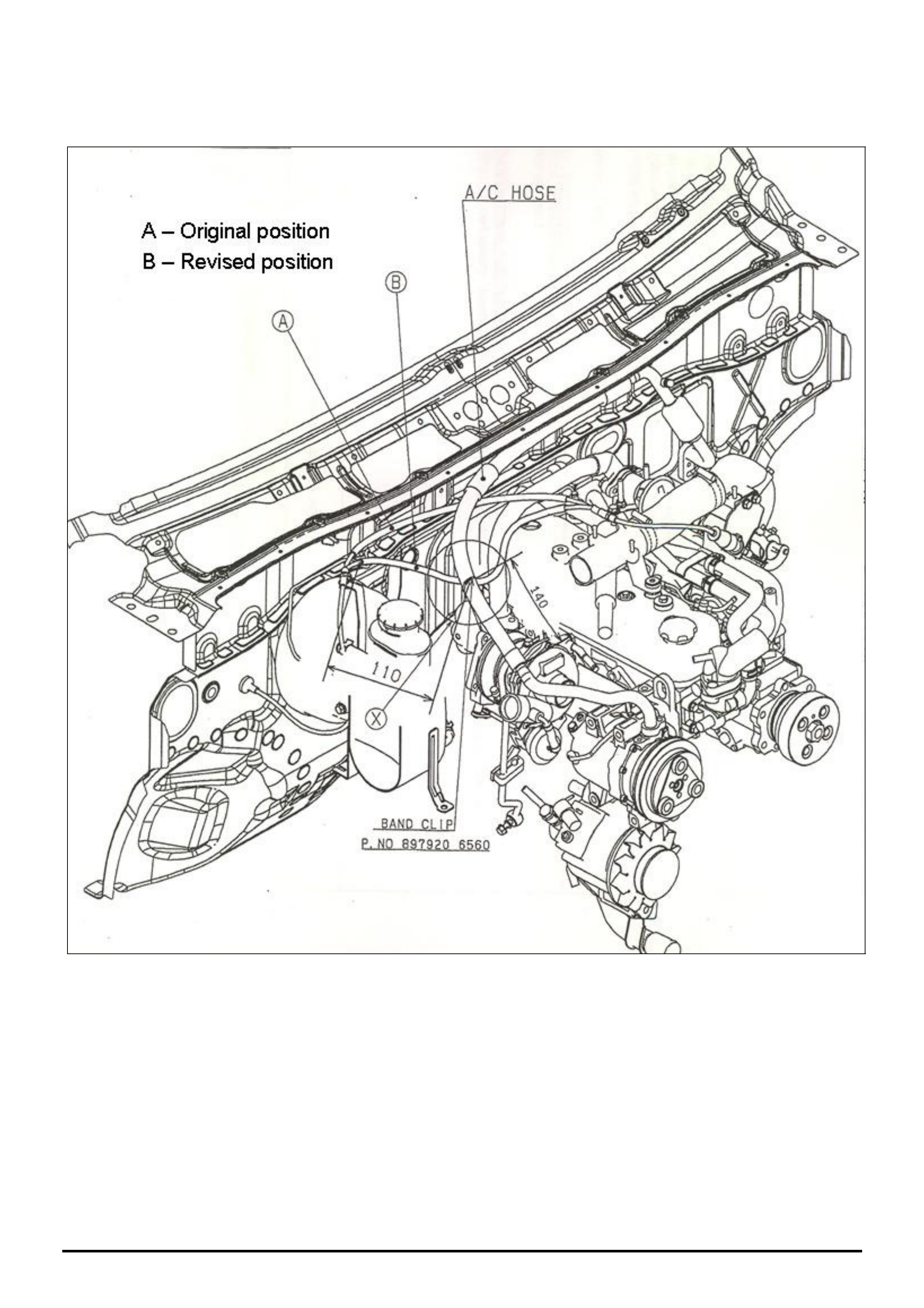
(2) Re-route accelerator cable as shown in Figure 1
using a cable tie as shown in Parts Information.
Ensure that the accelerator cable has no extreme
bends and operates correctly but with increased
effort.
NOTE: The accelerator cable can only be re-rerouted
on those vehicles where an accessory A/C kit has
been fitted.
PARTS INFORMATION
Part No.: Partfinder Name Qty:
8979206560 Clip band (cable tie) 1
WARRANTY CLAIM INFORMATION
Description Adjust TPS & reroute
accelerator cable
Labour Op. No. J000770
Time 0.3 hr
Failure Code J0033
HOLDEN SERVICE TECHLINE ________________________________________________________________________________APRIL, 2005
11
Holden Techlines are written to inform technicians of conditions that may occur on some vehicles, and to provide information that could assist in the
proper service fix of a vehicle. If a condition is described, do not assume the service fix applies to a vehicle or that the vehicle will have that condition.
Figure 1. Shows accelerator cable rerouted from position A to B
HOLDEN SERVICE TECHLINE __________________________________________________________________________________MAY, 2005
6
Holden Techlines are written to inform technicians of conditions that may occur on some vehicles, and to provide information that could assist in the
proper service fix of a vehicle. If a condition is described, do not assume the service fix applies to a vehicle or that the vehicle will have that condition.
INFORMATION
Seat Belts Replaced For Complaint Of
Not Extending
UES Frontera, YG Cruze, RA Rodeo
(GROUP 1) TL253B-0504
This Techline is repeated from Issue 4, April 2003
as dealers continue to replace seat belts for this
condition which is not a fault
PROBLEM DESCRIPTION
Numerous seat belts returned through the warranty
system cannot be faulted. The reason for
replacement of these belts is given as "seat belt will
not extend" or "seat belt jamming".
It appears that customers and Retailer staff may be
unaware of the Auto Locking Ratchet (ALR) system.
Refer to following for explanation of ALR.
Automatic Locking Ratchet (ALR) Mechanism.
The rear outer seat belts (all rears on RA Rodeo) and
left hand front seat belt have an Automatic Locking
Ratchet (ALR) mechanism. When this mechanism is
activated it will only allow the belt to retract. When
the mechanism is de-activated the belt can be
extended or retracted as normal.
To activate the ALR mechanism, extend the seat
belt to its maximum length.
To de-activate the ALR mechanism, allow the seat
belt to retract fully.
The ALR function may be useful as an additional
means of locating a child seat, when used in
conjunction with the approved child restraint anchor
points.
Note: It is always better to install a child restraint in
the rear seat.
SERVICE RECOMMENDATION
To avoid mis-diagnosis of seat belts, Holden Retailer
frontline staff should familiarise themselves with the
operation of the ALR system . They will then be able
to explain this feature to any customers who
complain that their seat belts “will not extend” or are
“jamming”.
NOTE: Seat belts replaced unnecessarily for
complaint of “not extending” will not be accepted as
warranty.
INFORMATION
TIS Approval with Tech 2
All Vehicle Types
(GROUP OB) TL0903-0504
PROBLEM DESCRIPTION
Programming difficulties when trying to link
immobilizers or program keys, may be attributed to
the incorrect process of obtaining TIS Approval on
Tech 2.
Some programming difficulties have occurred when
technicians have got TIS Approval on Tech 2 before
going to the vehicle. THIS IS NOT THE CORRECT
PROCEDURE
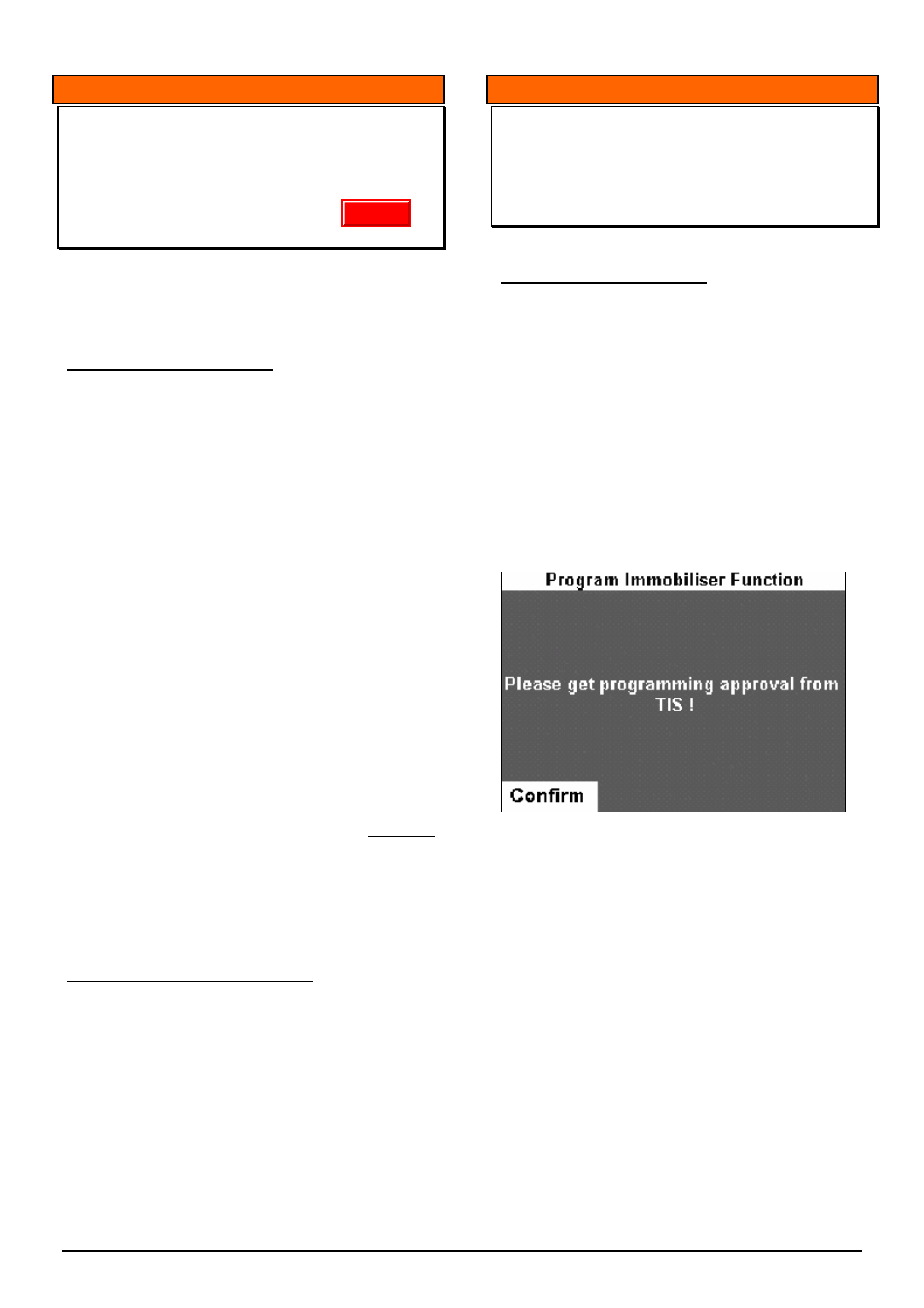
Dealers are reminded that the correct procedure for
obtaining TIS Approval is to only connect the Tech 2
to TIS, AFTER the following message is displayed on
the Tech 2 screen when Tech 2 is connected to the
vehicle.
Failure to follow this procedure may result in
programming failures or unnecessary parts
replacements.
Update

HOLDEN SERVICE TECHLINE __________________________________________________________________________________MAY, 2005
7
Holden Techlines are written to inform technicians of conditions that may occur on some vehicles, and to provide information that could assist in the
proper service fix of a vehicle. If a condition is described, do not assume the service fix applies to a vehicle or that the vehicle will have that condition.
DIAGNOSIS INFORMATION
Manual Transmission Rattle Noise in
Neutral at Idle
RA 4JH1 Diesel with M/T
(GROUP 7A) TL0910-0504
CONDITION
The vehicle may develop a “rattle” or “chatter” type
noise from the gearbox when the engine is at idle
and the gearbox is in neutral and foot is off the clutch
pedal.
The noise will go away when driven, or if the engine
RPM is increased.
The noise will go away when the clutch pedal is
depressed.
The noise may be intermittent.
CAUSE
The cause of the noise is currently under
investigation.
CORRECTION
If a vehicle is presented with the above complaint DO
NOT attempt any gearbox or clutch repairs - contact
TAS for further diagnostic assistance.
Update
HOLDEN SERVICE TECHLINE __________________________________________________________________________________MAY, 2005
8
Holden Techlines are written to inform technicians of conditions that may occur on some vehicles, and to provide information that could assist in the
proper service fix of a vehicle. If a condition is described, do not assume the service fix applies to a vehicle or that the vehicle will have that condition.
SERVICE FI
X
Muffler Cracks at inlet and outlet pipes.
RA Rodeo V6 Petrol Engine
Group 8 Ref. No. TL0876- 0504
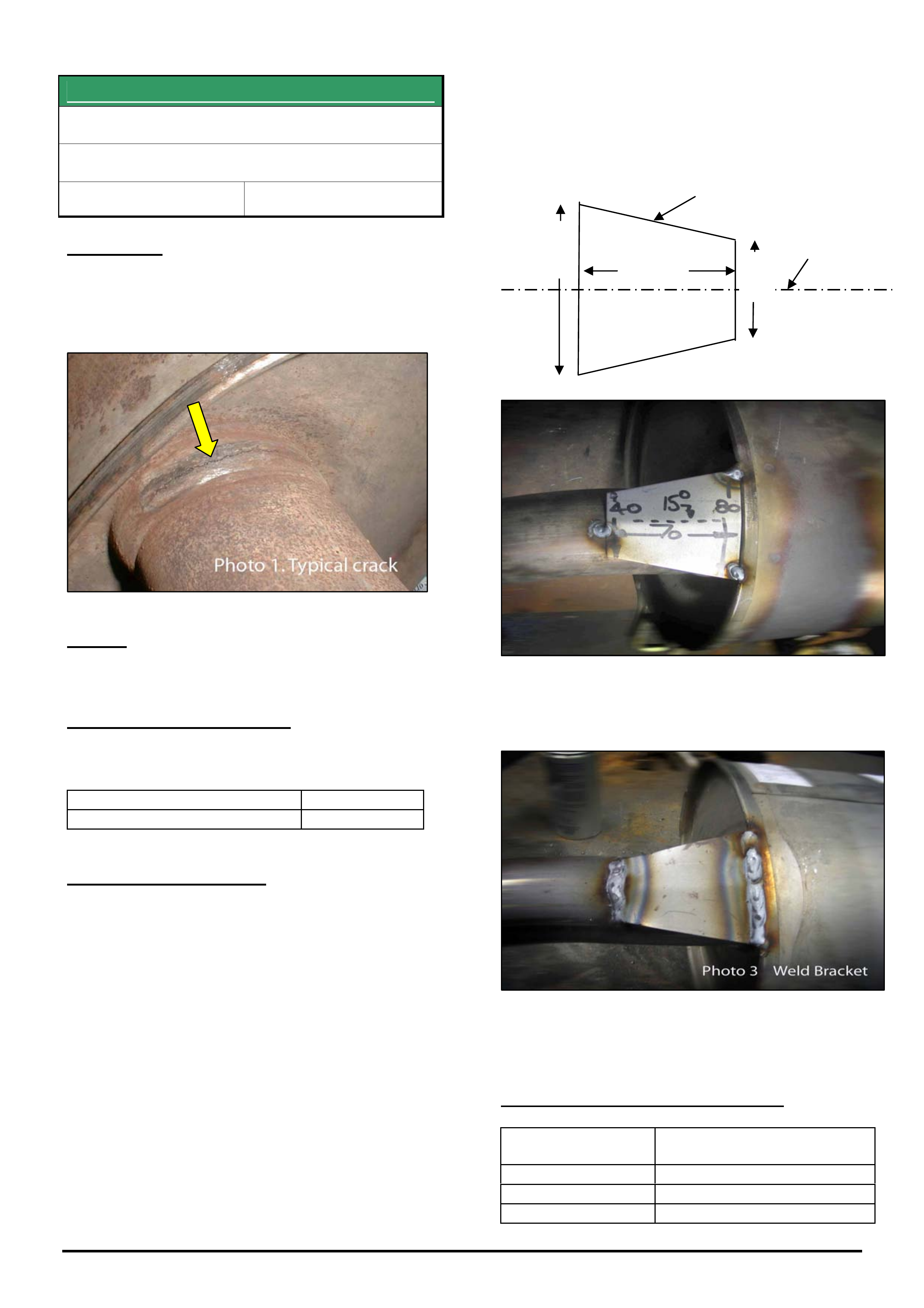
CONDITION
Cracks form at the inlet and/or outlet pipe of the
muffler where the pipe joins to the muffler. Refer
Photo 1.
CAUSE
Insufficient integrity of weld.
CORRECTION – Production
Mufflers manufactured with improved welding
process have been fitted to vehicles from:
ISOVIN: Built Date:
MPATFR26H5H538834 20/01/05
CORRECTION – Service
Step 1. Re-weld crack/s at inlet and/or outlet pipe.
If weld is cracked or damaged beyond repair then
replace the muffler.
Step 2, Fabricate two support brackets as per
sketch below. Even if both pipes are not cracked, a
support bracket is required at both inlet and outlet
pipe.
Step 3. Fillet weld fabricated brackets to
muffler inlet and outlet pipes as per Photo 3 below.
Step 4. Paint brackets and welded surfaces with
Zinc Rich Primer or similar.
WARRANTY CLAIM INFORMATION
Description Muffler - repair crack and
weld on brackets
Labour Op. No. L000251
Time 0.8 hr
Failure Code L0002 weld broken
80mm
70mm
40mm
2mm steel
plate
Bend 15° along
centre line
Bend 15° along
centre line
HOLDEN SERVICE TECHLINE __________________________________________________________________________________MAY, 2005
16
Holden Techlines are written to inform technicians of conditions that may occur on some vehicles, and to provide information that could assist in the
proper service fix of a vehicle. If a condition is described, do not assume the service fix applies to a vehicle or that the vehicle will have that condition.
INFORMATION
Checking TIS 2000 Version Number
GROUP OB TL0924-0504
The latest version of TIS (and other service
information Cd’s) is published at the beginning of
each Techline Issue under the heading:-
‘Your Latest Electronic Service Information’.
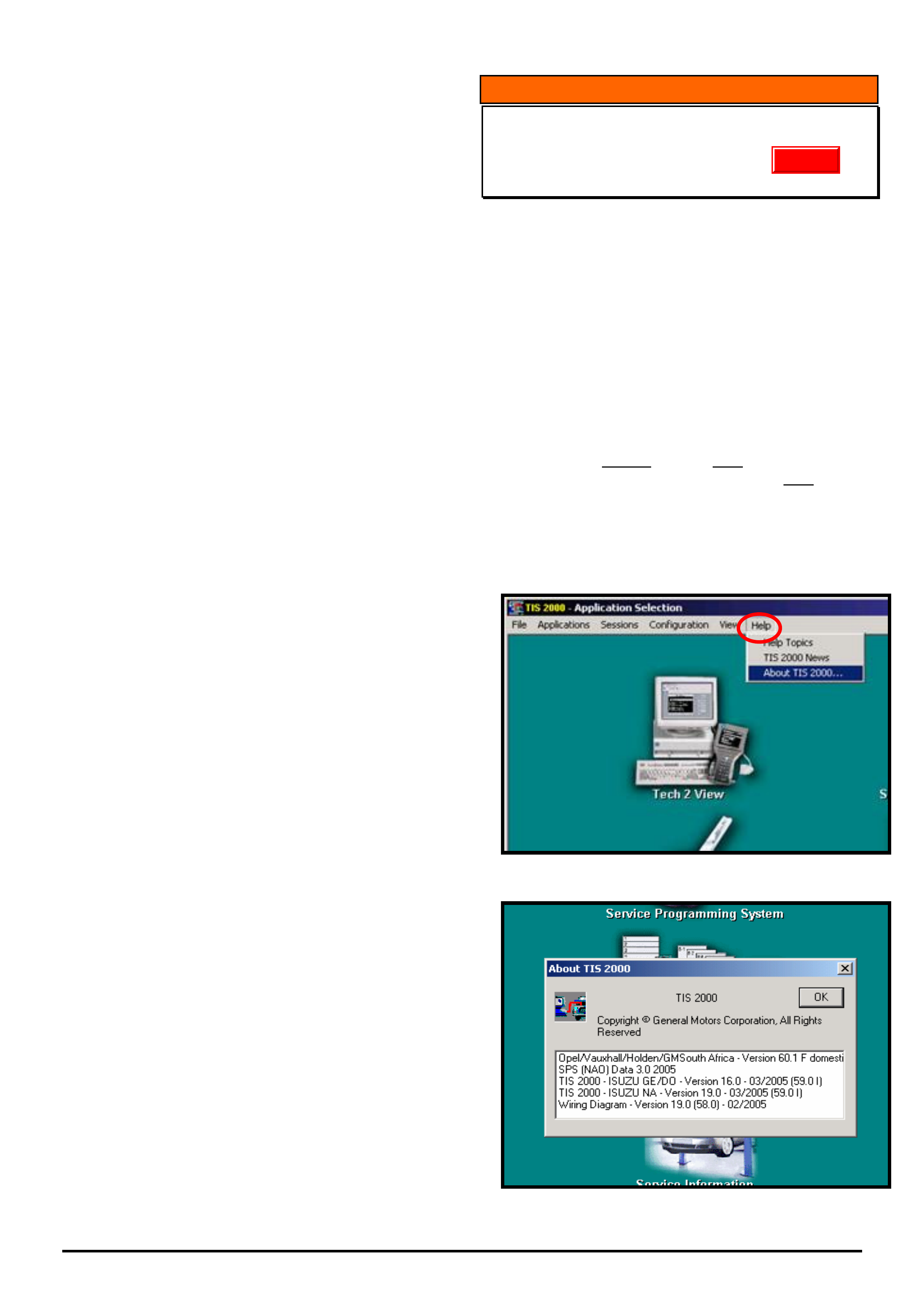
To confirm which version of TIS2000 is loaded on
your PC proceed as follows.
From the TIS main screen click ‘Help’ from the top
menu bar, then click ‘About TIS 2000’ refer Figure 1.
In the ‘pop up’ is the current version of service
information installed. Refer figure 2.
In this example the current version is:
Opel/Vauxhall/Holden/Version 60.1 Domestic.
TIS 2000 – Isuzu GE/DO Version 16.0 (Isuzu
General Export Domestic)
Wiring Diagram – Version 19.0
Note: For instructions on how to download TIS 2000
Isuzu software into Tech 2, refer Techline Issue 2
March 2004.
Figure 1.
Figure 2.
Update
HOLDEN SERVICE TECHLINE __________________________________________________________________________________MAY, 2005
18
Holden Techlines are written to inform technicians of conditions that may occur on some vehicles, and to provide information that could assist in the
proper service fix of a vehicle. If a condition is described, do not assume the service fix applies to a vehicle or that the vehicle will have that condition.
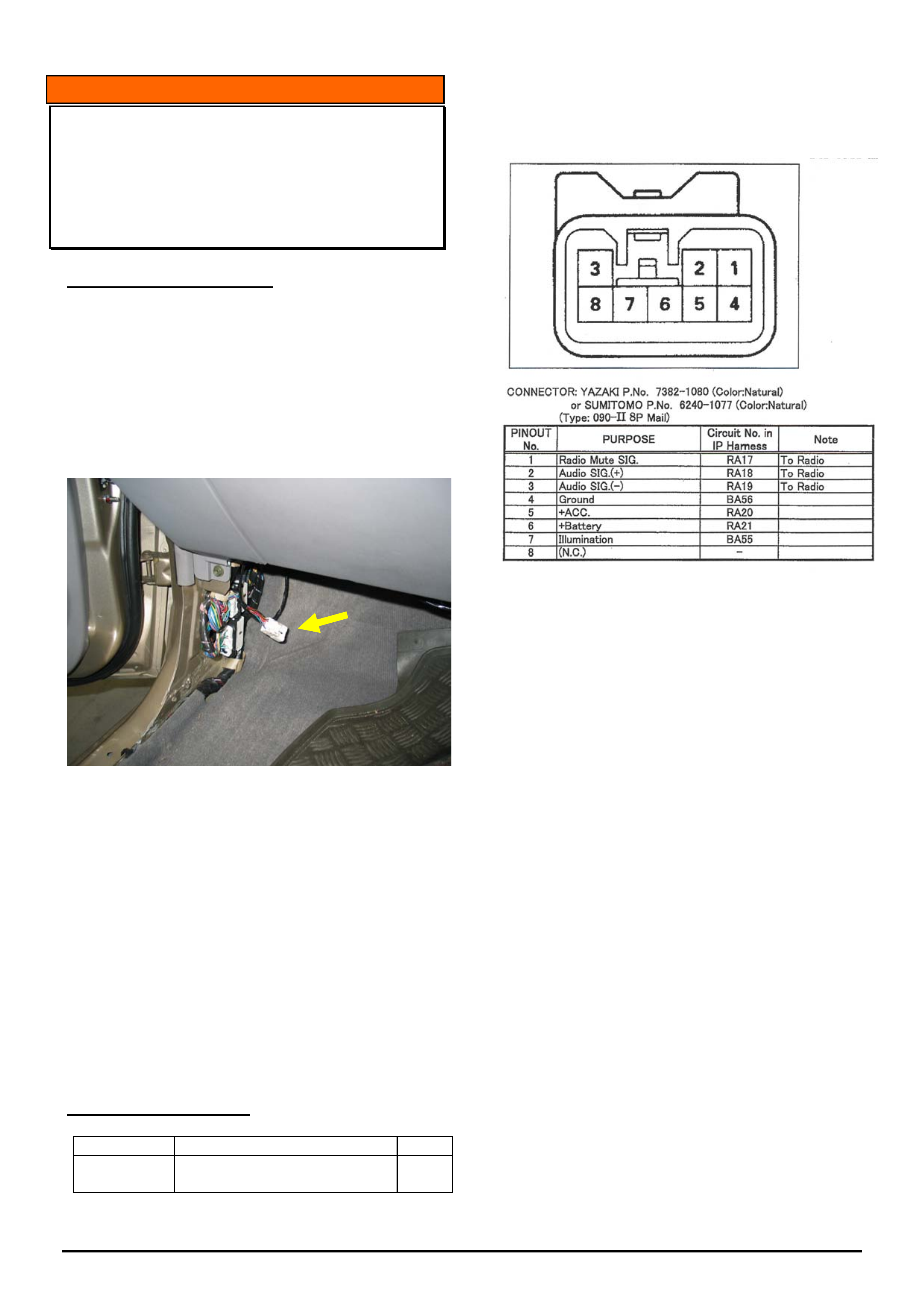
INFORMATION
Location of Mobile Phone Wiring
Connector
RA Rodeo
(GROUP 12) TL0922-0504
PROBLEM DESCRIPTION
TAS receive calls on electrical problems with RA
models that are the result of incorrect wiring of
mobile phones into the vehicles electrical system.
This highlights the fact that many installers of
aftermarket mobile phones are unaware of the
location of the cellular phone connector which is
located in the LH kick panel area as shown in Figure
1.
Figure 1.
The pin configuration for this connector is shown in
Figure 2.
At the time of publication of this Techline it is
confirmed that pins 2 and 3 do NOT work in
conjunction with the standard Audio Units fitted to
these Vehicles.
In addition, pin 4 is not “Ground” and may NOT be
used.
NOTE: A mobile phone patch harness is available for
this connector from H.S.P.O.
For part number refer to Partfinder / RA Rodeo/
Accessories / Telephone Fittings.
PARTS INFORMATION
Part No.: Partfinder Name Qty:
92147932 Harness Patch Mobile Phone
1
Mobile Phone Connector
(IP Harness side)
Figure 2.
HOLDEN SERVICE TECHLINE __________________________________________________________________________________JUNE, 2005
5
Holden Techlines are written to inform technicians of conditions that may occur on some vehicles, and to provide information that could assist in the
proper service fix of a vehicle. If a condition is described, do not assume the service fix applies to a vehicle or that the vehicle will have that condition.
TECHLINE CORRECTION
“Fuel Gauge Reads Empty With 25 Litres Left
In The Tank – RA Diesel”
Published in Issue 4, May 2004, Page 16.
Ref. No. TL0576-0404
Please correct your copy of the above Techline as
follows:
In the breakpoint table, alter the date for the 2x4 model
to read 10/11/03 as shown.
ISOVIN: Built Date:
MPATFR77H4H514631 (2 X 4) 10/11/04 03
MPATFS77H4H515657 (4 X 4) 19/11/03
INFORMATION
Searching for Techlines, Dealer Letters etc. on
Holden Lionheart (Portal)
(GROUP OB) TL0921-0504
This Techline describes two methods for locating
Techlines, Dealer Letters, Campaign Bulletins etc. on
Holden Lionheart.
• CONVENTIONAL method
• SEARCH ENGINE method.
The CONVENTIONAL method is similar to looking up
information in a text book. You commence by looking
in the Table Of Contents at the front of the book then
looking up the page reference then scanning down the
page until you find the section you’re looking for.
The “SEARCH ENGINE” method involves entering
your search criteria in a Search window and then
letting the search engine find the techlines
automatically.
HOLDEN SERVICE TECHLINE __________________________________________________________________________________JUNE, 2005
14
Holden Techlines are written to inform technicians of conditions that may occur on some vehicles, and to provide information that could assist in the
proper service fix of a vehicle. If a condition is described, do not assume the service fix applies to a vehicle or that the vehicle will have that condition.
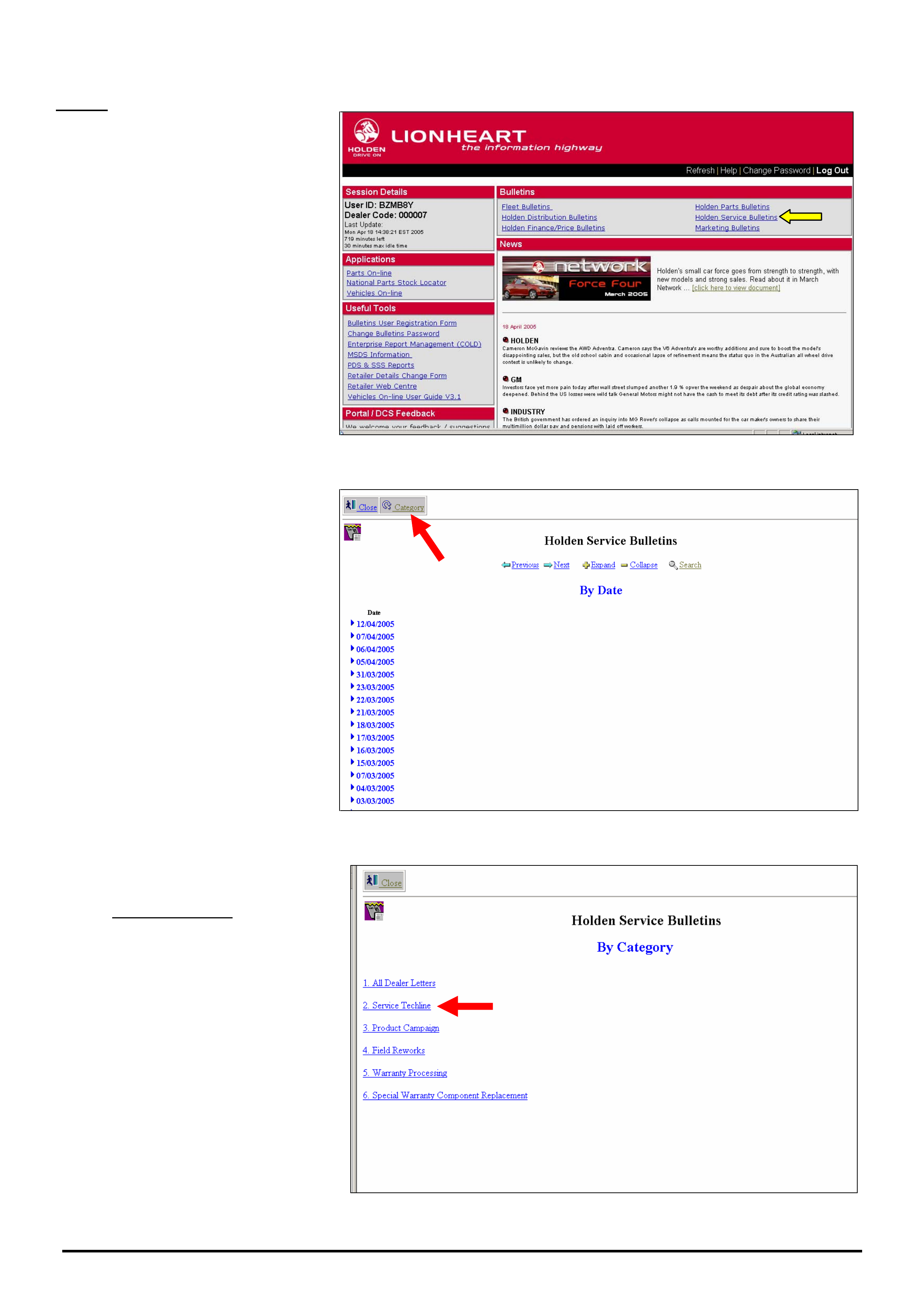
START
1. After logging onto Holden
Lionheart select “Holden Service
Bulletins” as indicated by yellow
arrow.
Figure 1.
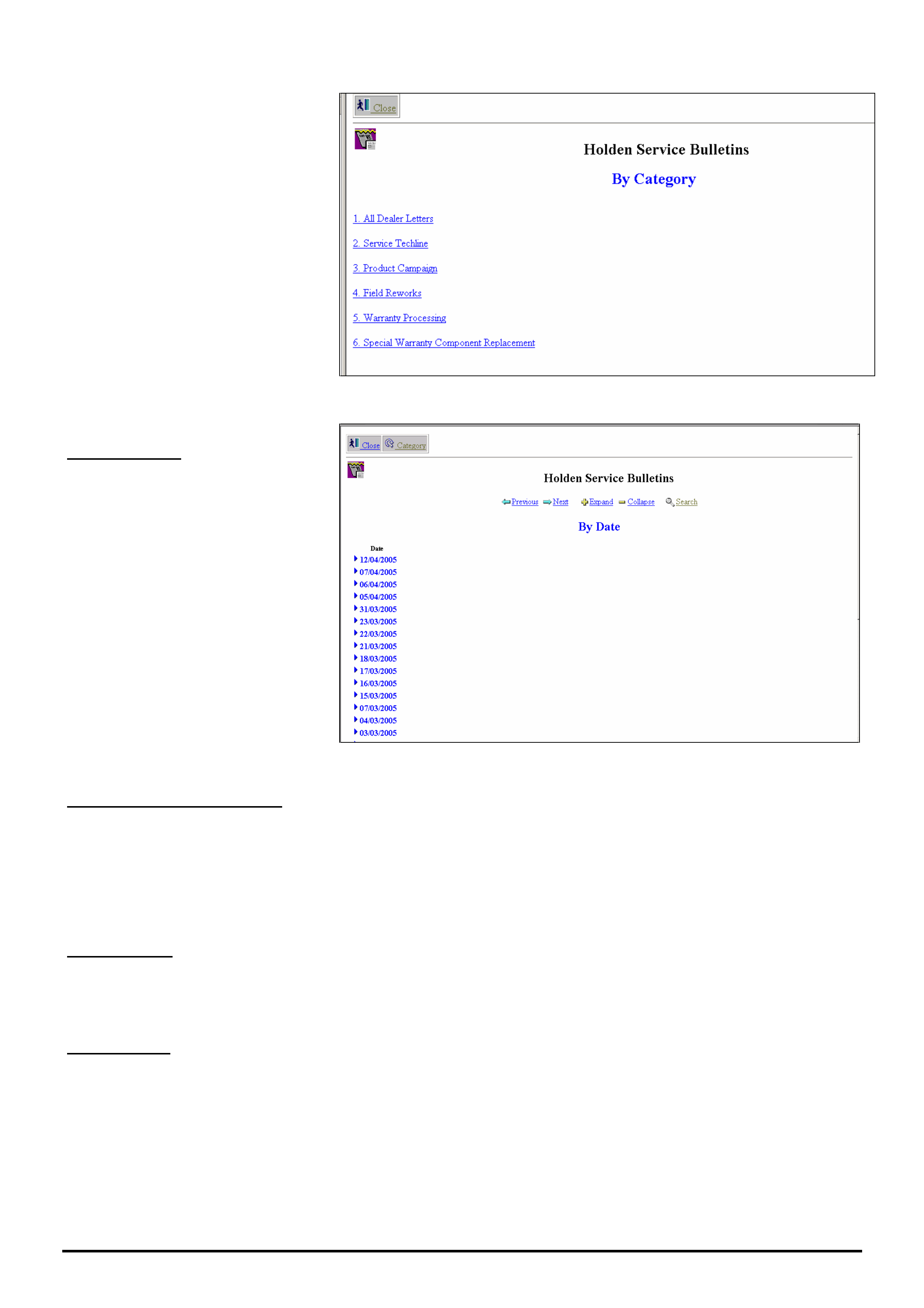
2. The next screen to appear shows
all items in the Holden Service
Bulletin Database arranged by Date.
The most recent items are on the top
of the list. To view the item, click on
the ►next to the date.
HINT: Check this screen everyday
to view the latest information
issued by Holden Service
Department.
If you select the “Category” button as
indicated by red arrow, the screen
shown in Figure 3 will appear.
Figure 2
3. In this example we will show how
to locate a Service Techline. Now
select “Service Techline” from the list
shown.
The next screen to appear is shown
in Figure 4 on next page.
Figure 3.
HOLDEN SERVICE TECHLINE __________________________________________________________________________________JUNE, 2005
15
Holden Techlines are written to inform technicians of conditions that may occur on some vehicles, and to provide information that could assist in the
proper service fix of a vehicle. If a condition is described, do not assume the service fix applies to a vehicle or that the vehicle will have that condition.
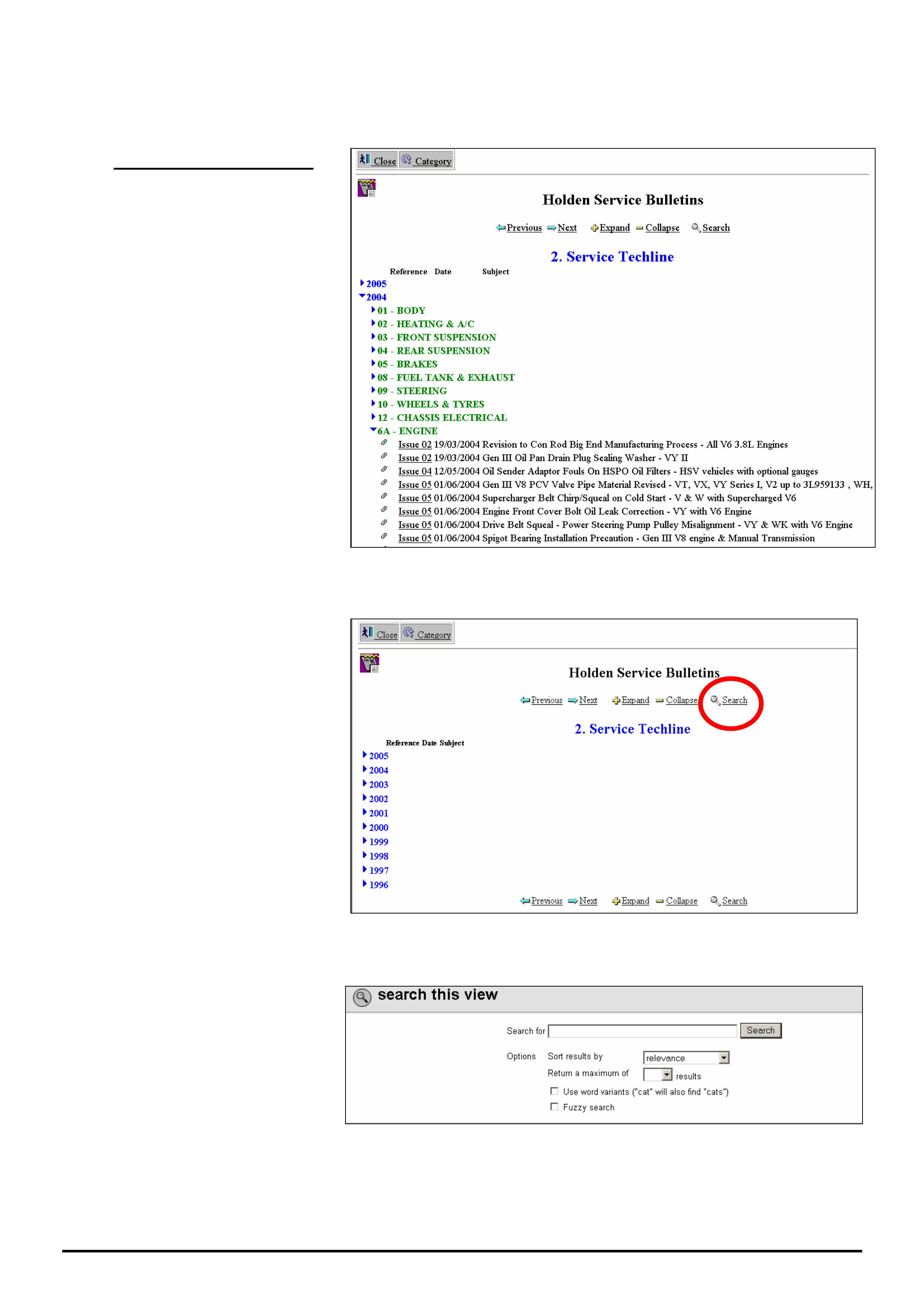
Following is a description of how to locate information by the conventional method or by using the search
function.
4 (A). Conventional Method.
As an example, we will look for a
techline on
V
Y V6 oil leak from
engine front cover.
Choosing the right year and the right
Group to look in are the keys to
finding a techline quickly.
As VY was produced from 2002 to
2004 you should commence looking
in 2004. Choose group 6A – Engine
and look through list of techlines until
you find the right one, which in this
example was published in Issue
05/2004
The drawback with this
“Conventional” method is knowing
which year and group to look in. It
can also be time consuming
scanning through long lists of
techlines.
Figure 4
4 (B). SEARCH-Function
Method
From the screen shown in Figure 5,
click on the “Search” key. This will
bring up the screen shown in Figure
6.
Figure 5
This is the search screen we use for
entering our search criteria (i.e. an
accurate summary of what we are
searching for)
Figure 6
HOLDEN SERVICE TECHLINE __________________________________________________________________________________JUNE, 2005
16
Holden Techlines are written to inform technicians of conditions that may occur on some vehicles, and to provide information that could assist in the
proper service fix of a vehicle. If a condition is described, do not assume the service fix applies to a vehicle or that the vehicle will have that condition.
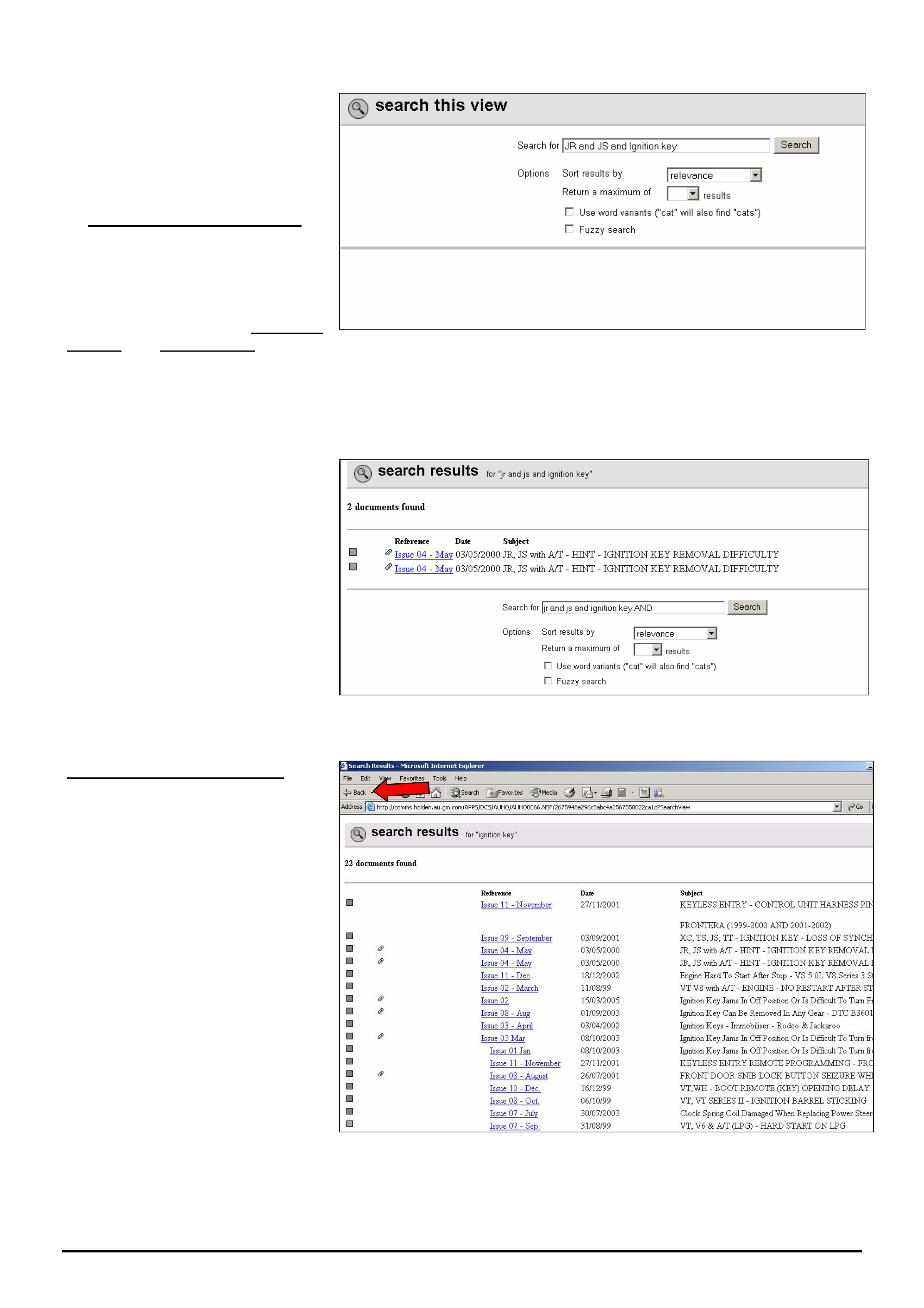
As an example we will search for
techlines related to JR & JS Vectra
Ignition Barrel Jamming.
In the “Search for” window, type in
the following “search string”.
“JR and JS and Ignition key”.
Don’t touch the next 2 boxes titled
“Sort results by” or “Return a
maximum of”.
Tick the last 2 boxes i.e. Use Word
variants and Fuzzy search. Refer to
later explanations of these terms.
Now click the “Search” button.
Figure 7
The search result is 2 documents as
shown in Figure 8.
Click on the hot-key section (in blue)
to view the techlines.
Figure 8.
Defining Your Search Criteria
If we had entered only “ignition key”
in the search window the search
engine would have located 22
techlines as shown in Figure 8.
If we had entered only “ignition”, the
search engine would have located
85 techlines.
So you can see the importance of
defining your search criteria as
accurately as possible so you don’t
end up with huge numbers of items
to read through.
Rule of thumb: the less information
in the “search window” the more
information comes back.
If at anytime you wish to go back to
the “Search” function press the
“Back” arrow in the top left side of
the toolbar. Refer red arrow.
Figure 9.
HOLDEN SERVICE TECHLINE __________________________________________________________________________________JUNE, 2005
17
Holden Techlines are written to inform technicians of conditions that may occur on some vehicles, and to provide information that could assist in the
proper service fix of a vehicle. If a condition is described, do not assume the service fix applies to a vehicle or that the vehicle will have that condition.
To search for a Dealer Letter,
Campaign Bulletin, Field rework or
Warranty Bulletin, use the same
procedure as that described for a
Service Techline.
IMPORTANT: You must first select
the category you want from the
Category screen (Figure 10) before
proceeding with search.
Figure 10.
General Search.
To find ALL published information on
a subject, select “Search” from
screen shown in Figure11.
As an example, enter “Daewoo” in
the search field
This “search” will give you everything
that contains the word “Daewoo” .eg.
Dealer letters, Techlines, Recalls,
Warranty etc.
Figure 11
General Notes On Searching.
• If you perform a search and the results are not what you were looking for; to conduct another search, you will
need to hit the “← Back arrow” in the Microsoft Internet Explorer menu at top left of page. This will bring up a
new search window that you can enter new search criteria into after deleting the previous search criteria.
• The search engine cannot search any “attached” files such as Word, Excel, Pdf, on Holdens database. It can only
search for words that appear on the viewing page for each individual item.
Word Variants
If you tick this box in the search panel, and type in “cat” in the “Search For” window, the search engine will find every
word that has cat in it, eg. catalytic, category, cats, etc. This is useful if you cannot remember the exact spelling of a
word or you forget the s when the word is plural.
Fuzzy Search.
EXAMPLE 1. Search for techlines with DTC P0335 in the Subject title.
If you accidentally type in DTCP0335 without a space between C and P, and do a Fuzzy search, the search engine
will still bring up all techlines containing “DTC P0355”.
EXAMPLE 2. Search for techlines containing 4JX1 in the subject title.
If you accidentally type in 4JX, a fuzzy search will still find all techlines with 4JX1 in the title. This feature doesn’t
seem to work if you forget to enter the first letter. in this example, doing a Fuzzy search on JX1 will not find anything.
HOLDEN SERVICE TECHLINE __________________________________________________________________________________JULY, 2005
Holden Techlines are written to inform technicians of conditions that may occur on some vehicles, and to provide information that could assist in the
proper service fix of a vehicle. If a condition is described, do not assume the service fix applies to a vehicle or that the vehicle will have that condition.
DIAGNOSIS INFORMATION
Hard Start or No start
RA RODEO Petrol & Diesel
(GROUP 6C) TL0955-0506
This techline is written to assist in diagnosis of
any RA Rodeo with a complaint of hard start or
intermittent no start.
A vehicle can be difficult to start for many reasons.
Attempting to diagnose a hard start / no start condition
without all the relevant information may lead to wrong
diagnosis and unnecessary parts replacement.
If the fault is intermittent and cannot be reproduced in the
workshop, then the owner must be questioned to get the
relevant information to allow the fault to be reproduced.
THE FOLLOWING INFORMATION IS REQUIRED AS A
MINIMUM BEFORE ATTEMPTING TO DIAGNOSE A
HARD/NO START CONDITION.
Owner Questions should include the following.
1. Does the engine - Crank / Not crank / Crank Partially /
Start & then Stall ?
2. Does the Engine Check Light (MIL) flash when the
vehicle won’t start?
3. How does the owner get car started?
4. Are there any electrical accessories fitted to the
vehicle at the time of hard start? E.G. UHF radio, phone
charger, either hard wired or plug in type, service lights
ETC, If so where are these accessories wired to ?.
NOTE: Electrical accessories that are incorrectly wired
into the vehicle can cause hard start problems, and must
be fixed before further diagnosis.
After the above information is determined, continue with
the following workshop checks.
Workshop Checks
1 What is the open circuit voltage & cranking voltage of
the vehicle battery ?
Cranking voltage should be above 10.5 Volts.
2 Are there any DTC’s logged in the engine ECU or
the Immobiliser ICU? If so, what are they? Include the
fault code number & Tech 2 descriptions ?
If Present DTC’s are shown, perform the relevant flow
chart diagnosis for the DTC’s SEE NOTE A
If History DTC’s are shown, the DTC charts can still be
used to identify & check the relevant circuits & wiring
associated with the DTC.
NOTE A. DTC B8007 can be set falsely by cycling the
Ignition key from On – Off – On within 30 seconds. Do
not diagnose by this code if this is the case.
NOTE B. If there are no DTC’s in the engine or
Immobiliser ICU, the problem is probably NOT
Immobiliser related. In this case, perform usual engine
no start / hard start diagnosis, E.G. fuel pressure, fuses,
power & earth supplies, etc. Use Tech 2 typical data
values to help in diagnosis.
3 Remove & clean Earth points C-2 & C-109, Refer
LCRV SIP – System Electrical – Electrical Body &
Chassis - Grounding Point
4 Is the vehicle built after the following breakpoints for
the revised type immobiliser ?
V6 MPATF*26*4H539342
L4 MPATFR32J4H540437
DIESEL MPATF*77*4H536880
Vehicles built after the above VIN Numbers will already
have the revised type immobiliser fitted therefore go to
step 6
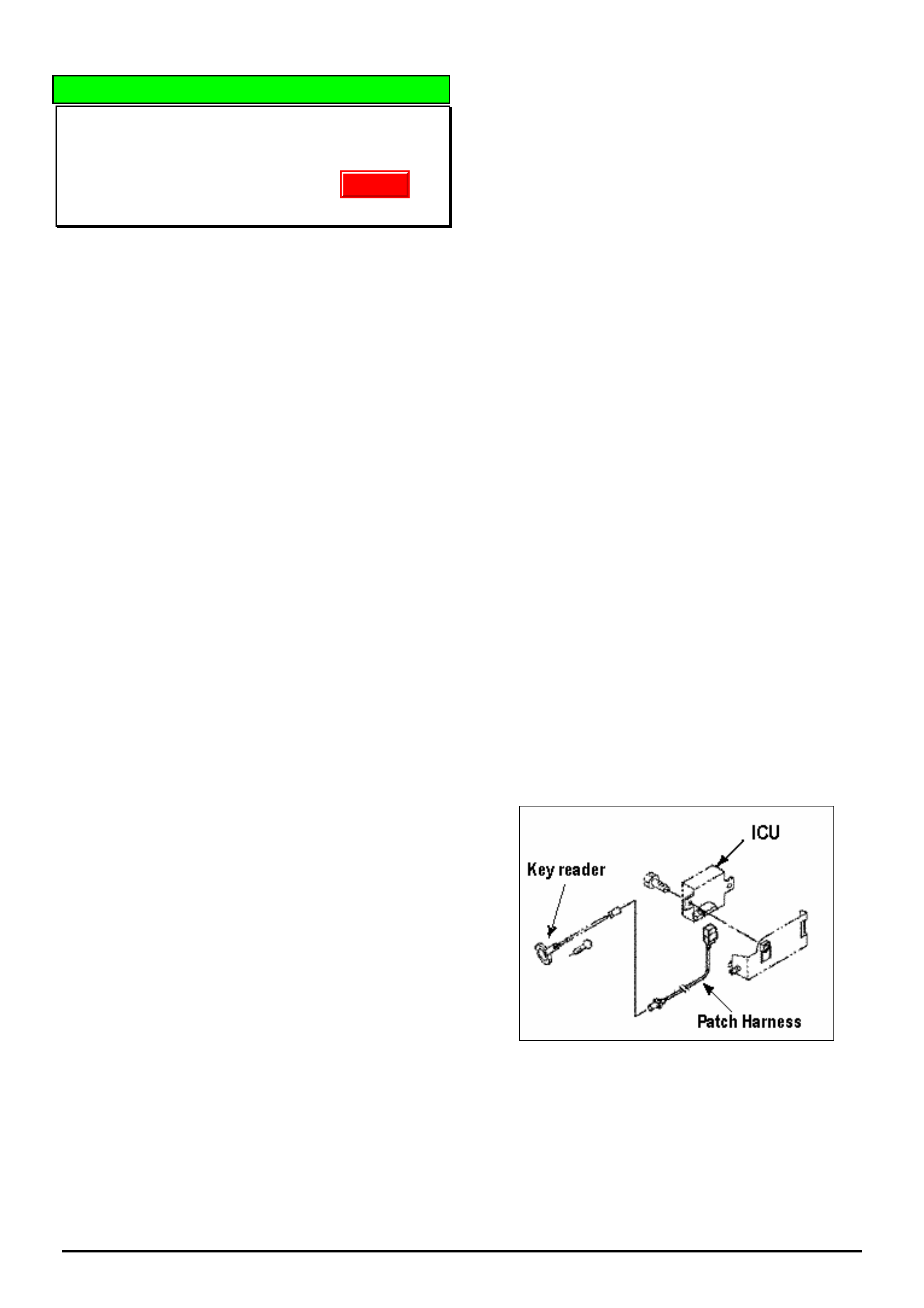
5 What is the Part Number of the Immobiliser ICU fitted
to the vehicle ? This can be read off the sticker on the
ICU. The Part Number should be as follows:
Petrol Engines - 8973773230
Diesel Engines - 8973773240
If ICU Part Number is different to above, replace the ICU
(With Zone Approval), following the relevant Reset &
Programming Procedures in LCRV Sip
6 Check the Immobiliser ICU & Antenna Connector
terminal retention of all terminals.
HINT. This can be done by removing a male terminal
from the Antenna / Key reader Patch harness and use
this terminal to test retention of female terminals.
7 If the vehicle is a V6 before engine number 240817,
program engine ECU with the latest TIS software.
This should be, 97389275 – 2750. SPS if required
NOTE Revised engine ECU software was fitted in
production from engine number 240817
If all above checks do not resolve the problem,
contact TAS for further diagnosis assistance.
Update
HOLDEN SERVICE TECHLINE __________________________________________________________________________________JULY, 2005
Holden Techlines are written to inform technicians of conditions that may occur on some vehicles, and to provide information that could assist in the
proper service fix of a vehicle. If a condition is described, do not assume the service fix applies to a vehicle or that the vehicle will have that condition.
SERVICE FIX
Brake Light Stays On
RA Rodeo
Group 5 Ref. No. TL0918 - 0506
This Techline is provided as an interim service fix
to be applied until further notice.
CONDITION
Customer complains that the brake lights stay on after
leaving the vehicle or that the brakes appear to be
dragging or sticking on.
CAUSE
Booster internal components not to specification
resulting in insufficient force in the system to return
the brake pedal to the “fully off” position.
CORRECTION – Production
Boosters with internal revisions to overcome the
above condition have been fitted to vehicles from:
ISOVIN: Built Date:
MPATFS77J5H517613 20/10/04
CORRECTION – Service
On complaint vehicles, the condition can be rectified
by increasing the tension of the brake pedal return
spring as follows.
Add a 10mm (min) thick rubber pad under the leg of
the spring as shown in Figure 1.
WARRANTY CLAIM INFORMATION
Description Add spacer to brake pedal
return spring
Labour Op. No. H000266
Time 0.2 hr
Failure Code H0033 weak
Figure 1.
Place spacer
under spring leg
Brake Pedal
Front of vehicle
HOLDEN SERVICE TECHLINE __________________________________________________________________________________JULY, 2005
Holden Techlines are written to inform technicians of conditions that may occur on some vehicles, and to provide information that could assist in the
proper service fix of a vehicle. If a condition is described, do not assume the service fix applies to a vehicle or that the vehicle will have that condition.
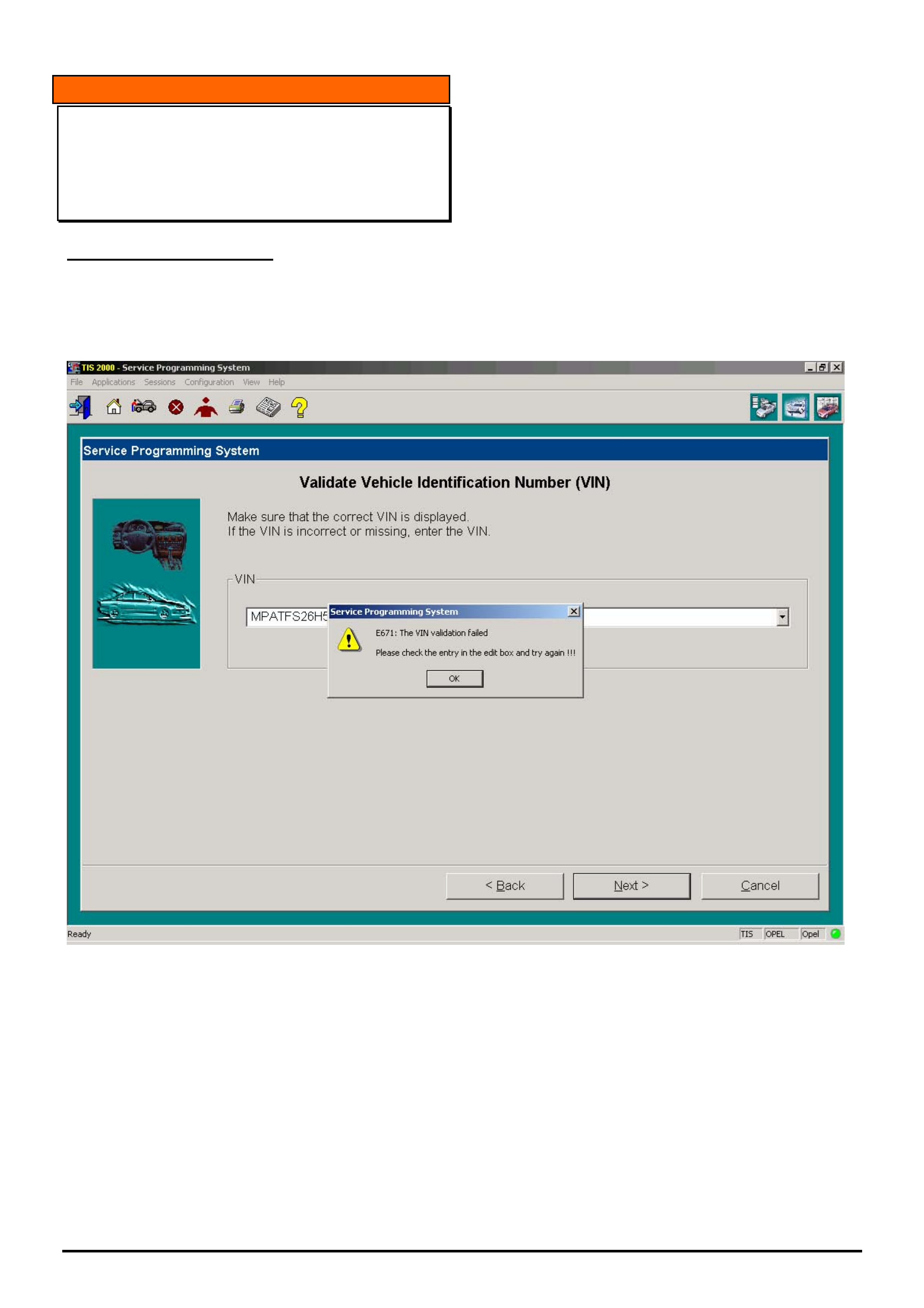
INFORMATION
TIS 2000 VIN validation failed message
LCRV TIS 2000
(GROUP OB) TL0951-0506
PROBLEM DESCRIPTION
When trying to carry out service programming (SPS)
on an LCRV product the message shown below may
appear.
One of the reasons for this message occurring is that
the LCRV TIS 2000 disc may not be loaded. This
may have been as a result of TIS 2000 being installed
on a new PC or if TIS 2000 was uninstalled and
reinstalled for some reason but the LCRV disc was
not loaded.
The Service Techline in Issue 4, 2005 (page 16)
describes how you can determine which discs are
loaded.
Note also that if the LCRV disc is not loaded then the
main TIS page will not have the “tech 2 view” icon as
it is loaded from the LCRV TIS disc.

HOLDEN SERVICE TECHLINE __________________________________________________________________________________JULY, 2005
Holden Techlines are written to inform technicians of conditions that may occur on some vehicles, and to provide information that could assist in the
proper service fix of a vehicle. If a condition is described, do not assume the service fix applies to a vehicle or that the vehicle will have that condition.
INFORMATION
Explanation of Driveline “Clunk” or “Backlash
Noise”
All Rear Drive Vehicles
Group 4 Ref. No. TL0956 - 0506
Some owners of rear wheel drive vehicles may
comment that the vehicle exhibits a “clunk” noise while
driving when the accelerator is depressed and then
released.
Similarly, owners of vehicles equipped with either
manual or auto transmissions may comment that the
vehicle exhibits a “clunk” noise when shifting between
Park & Drive, Park & Reverse or Drive & Reverse.
Whenever two or more gears interact with one another,
there must be a certain amount of clearance between
those gears in order for the gears to operate properly.
This clearance or freeplay (backlash) can translate into
a clunk noise whenever the gear is loaded and
unloaded quickly, or whenever the direction of rotation
is reversed.
The more gears/components you have in a system, the
more freeplay the total system will have.
The clunk noise that owners sometimes hear may be
the result of a stackup of freeplay (backlash) between
the components in the driveline.
For example: The potential for a driveline clunk would
be greater in a 4WD or AWD vehicle than in a 2WD
vehicle.
This is because in addition to the freeplay from the rear
axle gears, the drive shaft joints, and the transmission
(common to all vehicle types), the 4WD transfer case
and front drive shaft/s (and their associated
clearances) add additional freeplay to the driveline.
In service, dealers are discouraged from attempting to
repair driveline clunk conditions for the following
reasons:
• Driveline clunk is almost never the result of one
individual component with excessive freeplay, but
rather the result of the cumulative effect of
freeplay (backlash/lash) that is present in all of the
driveline components.
Because all of the components in the driveline
have a certain amount of freeplay (backlash) by
design, changing driveline components may not
result in a satisfactory freeplay (or driveline clunk)
reduction.
• While some owners may find the clunk noise
objectionable, this will not adversely affect the
durability or performance of the vehicle or its
components.
HOLDEN SERVICE TECHLINE _______________________________________________________________________________AUGUST, 2005
7
Holden Techlines are written to inform technicians of conditions that may occur on some vehicles, and to provide information that could assist in the
proper service fix of a vehicle. If a condition is described, do not assume the service fix applies to a vehicle or that the vehicle will have that condition.
DIAGNOSIS HINT
Erratic Tachometer Operation, and/or 4WD Not
Operating (if fitted)
RA Petrol or Diesel
(GROUP 12) TL0649A-0507
This Techline supercedes the previous one in Issue 2,
March, 2004. It is revised by adding a picture of the
location of the suspect fuse.
CONDITION
Erratic tacho or speedo operation and/or no 4WD
operation (if 4wd equipped).
CAUSE
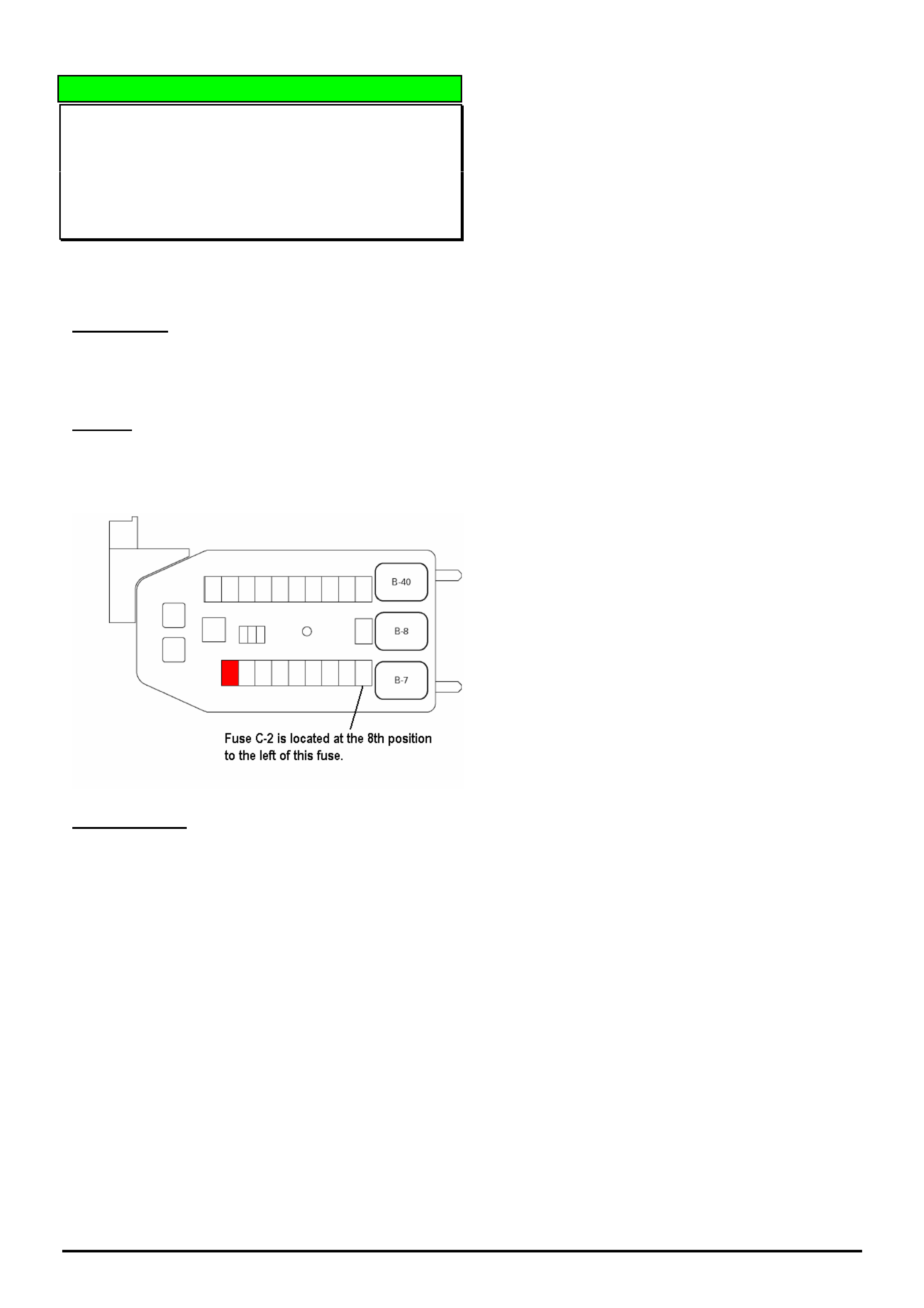
This condition may be caused by a blown or missing
fuse located at Fuse No. C-2 in the interior fuse box.
To locate fuse C-2 refer to following diagram.
CORRECTION
Verify that the ABS fuse at C-2 in interior fuse box isn’t
blown or missing.
NOTE: Vehicles without ABS require this fuse to be in
place for correct instrument cluster and 4WD
operation.
HOLDEN SERVICE TECHLINE _______________________________________________________________________________AUGUST, 2005
8
Holden Techlines are written to inform technicians of conditions that may occur on some vehicles, and to provide information that could assist in the
proper service fix of a vehicle. If a condition is described, do not assume the service fix applies to a vehicle or that the vehicle will have that condition.
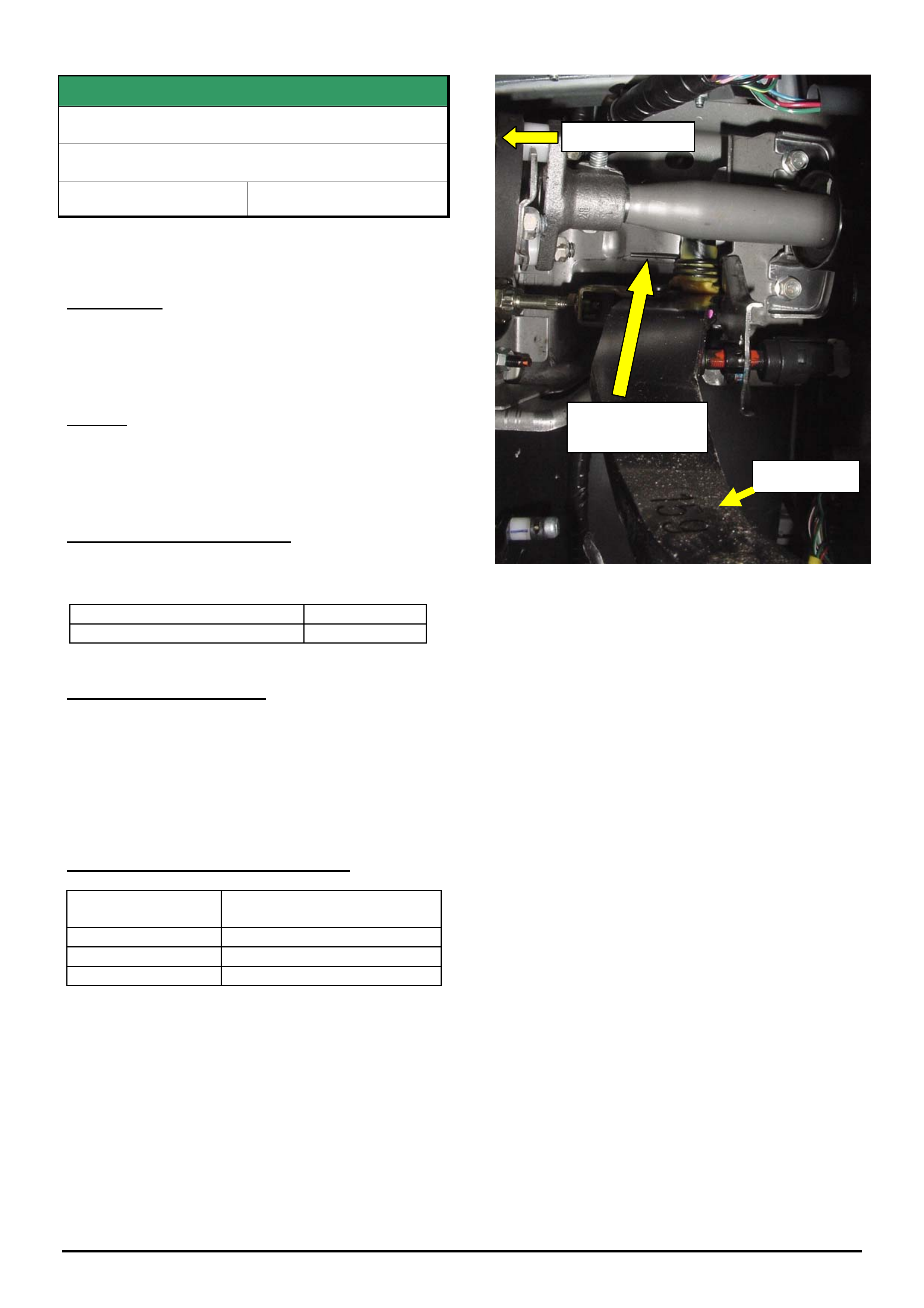
DIAGNOSIS HINT
Engine Vibration / Drone Noise at 2500-3000
RPM
RA RODEO Diesel 4JH1 With A/C
(GROUP 6A) TL0962-0507
PROBLEM DESCRIPTION
A vibration may be felt through the cabin of the vehicle
or a drone noise can be heard when engine RPM is
between 2500 - 3000 RPM. Complaint can be
reproduced in the workshop by revving the engine.
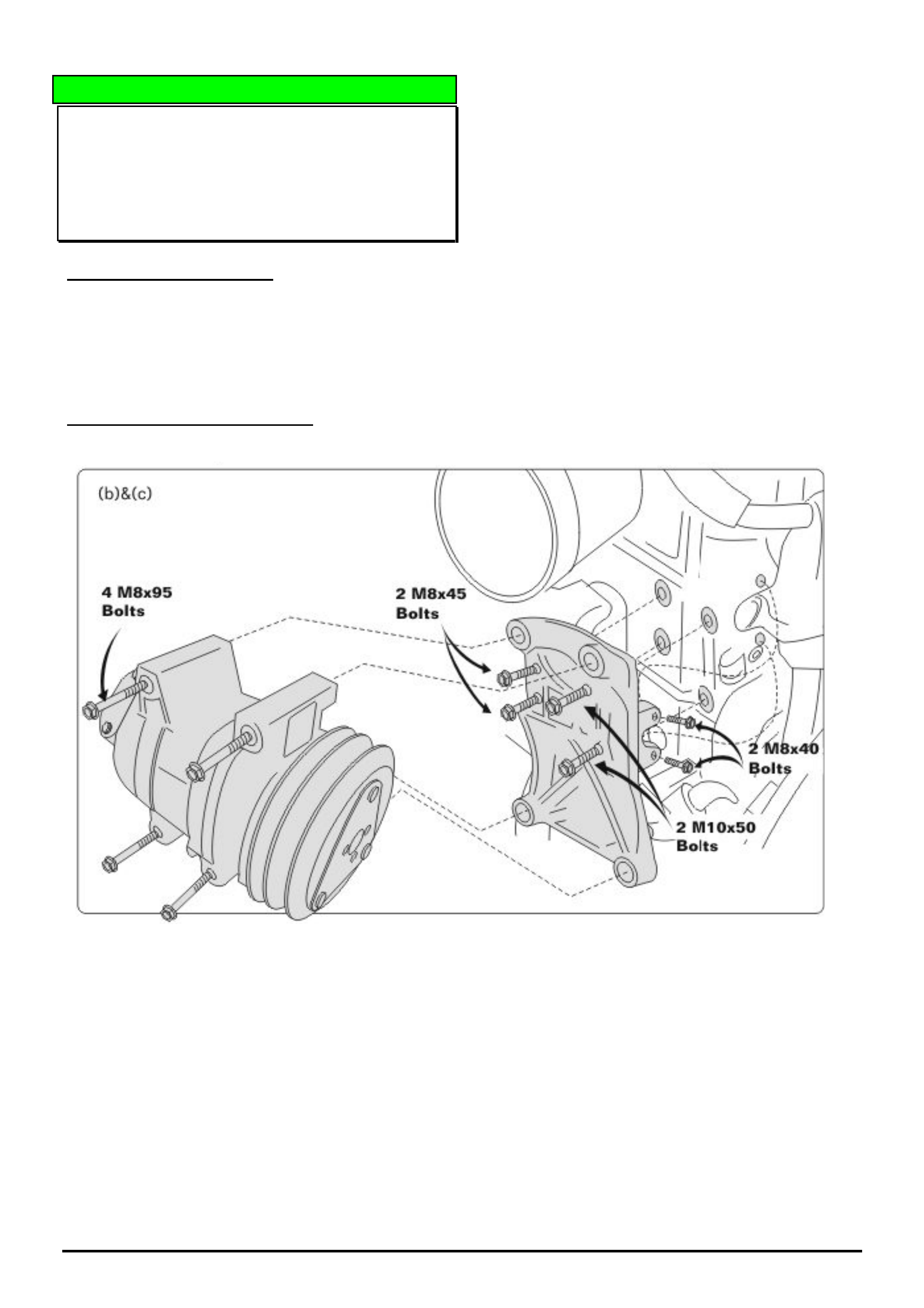
SERVICE RECOMMENDATION
Remove the A/C Compressor bracket mounting bolts
that hold the bracket to the engine as shown.
Note: There is no need to evacuate the A/C system.
Check the ends of the threads of M8 x 45 and M10 x
50 bolts for signs that the threads have bottomed out in
the threads of the engine (may be seen as 2 end
threads of the bolts are shiny) If it looks like the bolts
have bottomed out, place 2 mm flat washers under the
head of the bolts and retighten.
Note: Loosen the two front M8X40 bolts prior to
tensioning the four side bolts, then tension the front
bolts.
Refit compressor, adjust drive belt and retest to verify
that the vibration has been repaired.
HOLDEN SERVICE TECHLINE _______________________________________________________________________________AUGUST, 2005
9
Holden Techlines are written to inform technicians of conditions that may occur on some vehicles, and to provide information that could assist in the
proper service fix of a vehicle. If a condition is described, do not assume the service fix applies to a vehicle or that the vehicle will have that condition.
INFORMATION
TAS Vehicle Call Groups
Group OB Ref. No. TL0963 - 0507
TAS receive many calls where the caller has selected the incorrect group on the phone system for the vehicle model
they are enquiring about. Please refer to the following dialling options (numbers) when navigating through the TAS
phone system.
Introductory Message
HOLDEN dial 1 SAAB dial 2
Bulletin Board
- dial 1
LCV & Daewoo vehicles
- dial 2
• Jackaroo
• Frontera
• Cruze
• Rodeo
• ALL DAEWOO
badged vehicles.
Holden Passenger vehicles
- dial 3
• Commodore / sedan /
wagon / ute / 1 tonner /
crewman / AWD
• Statesman, Caprice
• Monaro
• Zafira
• Astra
• Vectra
• Barina
HOLDEN SERVICE TECHLINE ___________________________________________________________________________SEPTEMBER, 2005
7
Holden Techlines are written to inform technicians of conditions that may occur on some vehicles, and to provide information that could assist in the
proper service fix of a vehicle. If a condition is described, do not assume the service fix applies to a vehicle or that the vehicle will have that condition.
SERVICE FIX
Poor Engine Performance After Driving
Through Water or Washing Engine.
RA with 3.0L 4JH1 Diesel Engine
Group 6C Ref. No. TL0677A - 0508
This Techline supercedes TL0677-0404 published in
Issue 3, 2004. It is revised by including service fix
information.
CONDITION
Poor engine performance or lack of power after driving
through water or washing the engine.
CAUSE
This can be caused by dust in the Electrical Vacuum
Regulating Valve (EVRV) getting wet and blocking the
filter in the valve.
NOTE: The EVRV is located in the engine
compartment on the RHS guard area and its function is
to control the operation of the EGR valve.
CORRECTION – Production
A revised EVRV system was fitted to vehicles from:
ISOVIN: Built Date:
MPATFS77H5H581779 04/07/05
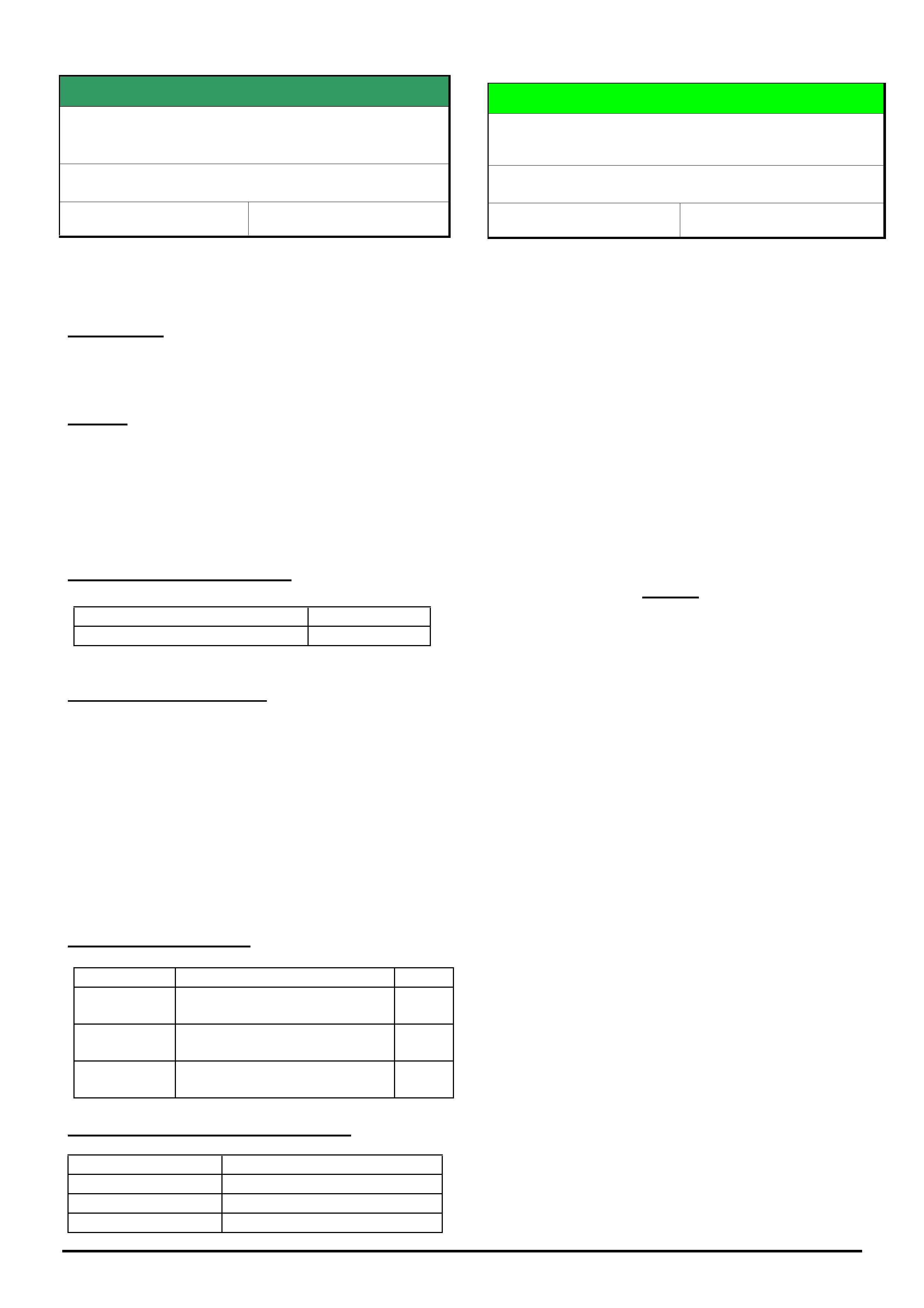
CORRECTION – Service
When diagnosing for the above condition, the vacuum
line to the EGR valve can be removed and plugged for
the duration of a test drive to confirm if it is the EGR
system that is causing the low performance.
THIS HOSE MUST BE RECONNECTED AFTER THE
TEST.
If the EGR valve is not operating correctly, remove the
EVRV, and visually inspect for dust or water entry to
the valve. If the valve is found to be contaminated it
must be replaced and new hose and duct fitted as
detailed on next page.
PARTS INFORMATION
Part No.: Partfinder Name Qty:
897374971
0
EGR Vacuum Valve 1
898009671
0
Hose EVRV to intake duct
(incl 3 clips)
1
898009695
0
Duct; Aircleaner to MAF (incl
2 clamps)
1
WARRANTY CLAIM INFORMATION
Description Install EVRV filtered air Kit
Labour Op. No. J000785
Time 0.3 hr
Failure Code J0012 foreign material
DIAGNOSIS HINT
Turbocharger Diagnosis / Oil Seep From
Intake Ducts
RA Rodeo – 4JH1 TC, UBS Jackaroo 4JX1
Group 6A Ref. No. TL0976 - 0508
This techline supersedes TL0731-0408 published in
Issue 8, 2004, titled Turbocharger Oil Leak Diagnosis.
Most of the turbochargers replaced under warranty for
engine oil consumption complaints cannot be faulted
when tested through REPAC.
Possible explanations for these Turbochargers being
replaced unnecessarily are:
1. Dealers may have incorrectly assumed that the
oil they are seeing in the intake ducts* is excessive and
is coming from the turbocharger seal.
2. The excessive oil consumption complaint may be
caused by another condition e.g. blocked air cleaner or
excessive engine blow by.
* - Why is there oil in the intake?
Turbochargers may “appear” to be leaking oil from the
impellor shaft in some cases when they are not. There
will be minimal oil residue on the intake side of the
turbocharger and oil wetness in the ducting after the
turbocharger. This occurs because atomised oil exits the
PCV system and collects in the intake, predominantly in
and after the turbocharger. Usually turbocharger failures
can be detected by noise and, in some cases, white
smoke.
Complaint Prevention:
Some complaints of leaking intake ducts may be
prevented by checking the hoses and clamps for the
intake ducting during service. It is good practice to
check the tension of intake duct hose clamps while
performing the under bonnet checks.
Leaking Duct Complaints:
The intake ducts should be resealed where possible.
Parts that appear to have a visual fault should be
replaced.
Oil Consumption Complaints:
No action should be taken for vehicles with an oil
consumption complaint until the sealing of the intake
duct has been checked and rectified when required. A
standard oil consumption test must be performed prior to
any major repairs. Where any components are replaced
for oil consumption the consumption rate must be
quoted in the 3C’s and TAS case where applicable.
Replacement Guidelines.
As a general rule, turbochargers should not be replaced
unless they are noisy or, in some cases, if the vehicle is
blowing white smoke.
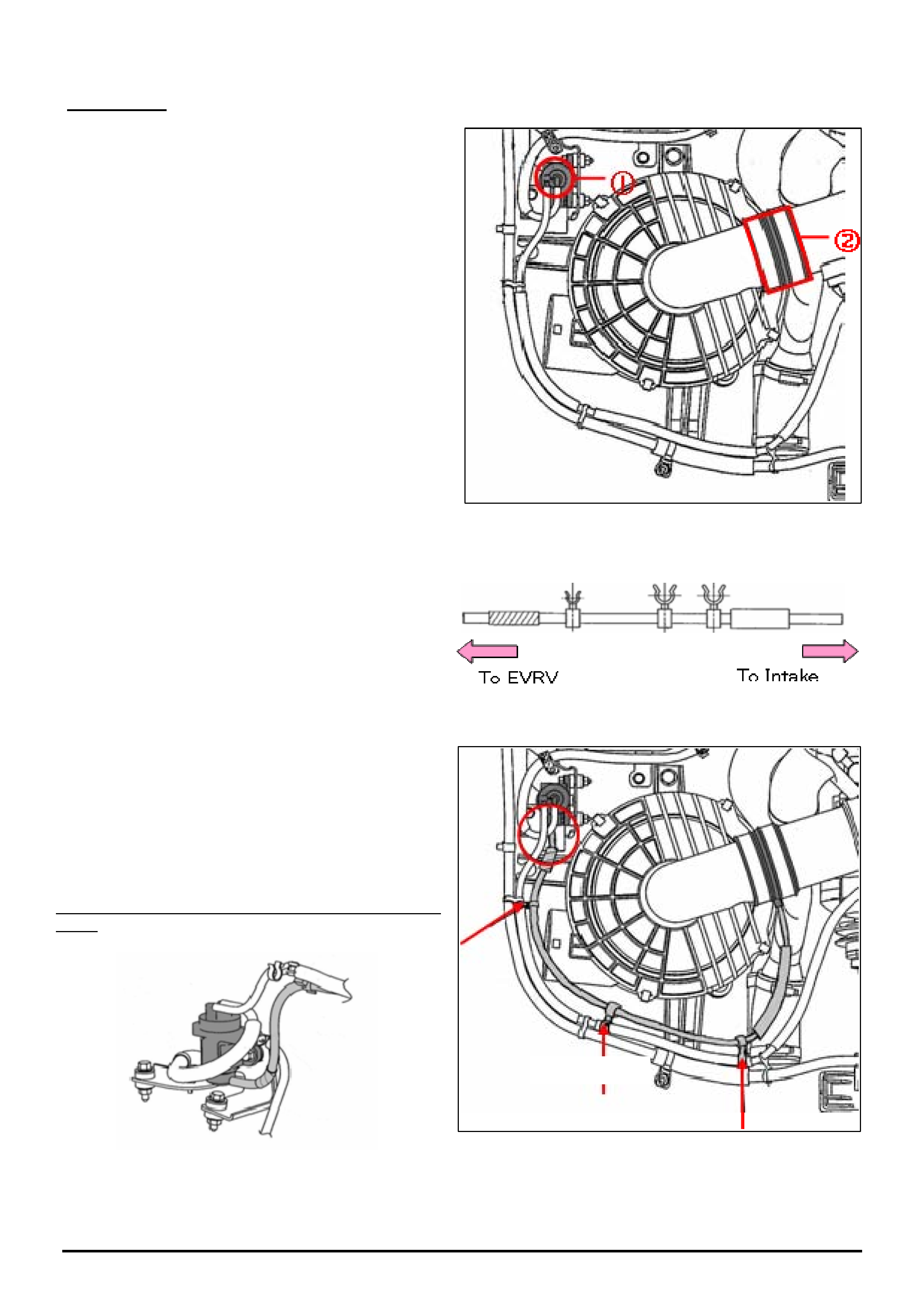
HOLDEN SERVICE TECHLINE ___________________________________________________________________________SEPTEMBER, 2005
8
Holden Techlines are written to inform technicians of conditions that may occur on some vehicles, and to provide information that could assist in the
proper service fix of a vehicle. If a condition is described, do not assume the service fix applies to a vehicle or that the vehicle will have that condition.
PROCEDURE
1. Remove EVRV and duct which sits between
the air cleaner box and the MAF sensor. In doing
so, ensure that dust will not enter the intake duct.
Refer Figure 1.
2. Install new EVRV; EGR (P/No. 8973749710) after
removing old valve.
3. Install new Duct Air cleaner to MAF (P/No.
8980096950). Ensure that positioning protrusions
are matched properly.
4. Install hose Part No. 8980096710 between the
EVRV and the Intake Duct.
NOTE, If this hose is not available, an alternative
hose can be manufactured from suitable vacuum
hose and attached in place with cable ties.
5. Attach the hose with clips at three locations as
shown by red arrows in figure opposite.
Enlarged view of connections to EVRV (within red
circle).
cli
p
–3
p
laces
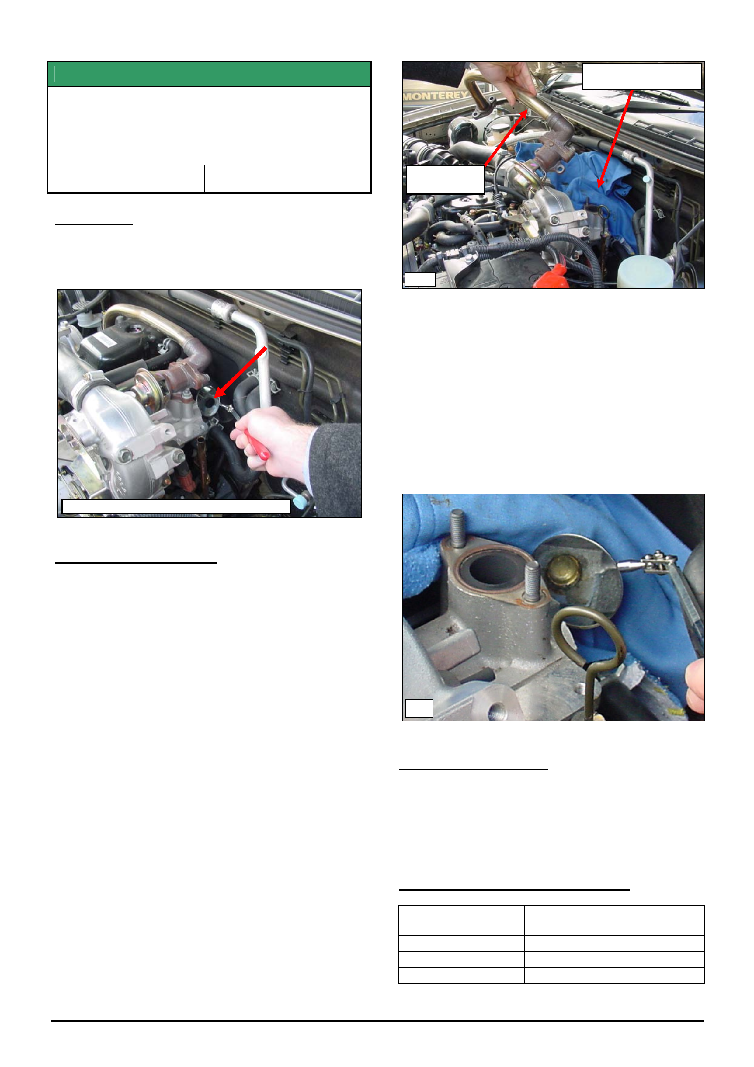
HOLDEN SERVICE TECHLINE ___________________________________________________________________________SEPTEMBER, 2005
9
Holden Techlines are written to inform technicians of conditions that may occur on some vehicles, and to provide information that could assist in the
proper service fix of a vehicle. If a condition is described, do not assume the service fix applies to a vehicle or that the vehicle will have that condition.
SERVICE FIX
Poor Performance Due To Plug Dislodging
From Rear Of The Intake Manifold
RA with 3.0L 4JH1 Diesel Engine
Group 6A Ref. No. TL0983- 0508
CONDITION
A small casting plug dislodges from the rear of the
intake manifold causing loss of turbo boost pressure
(refer Fig. 1).
CORRECTION – Service
Summary: Fit a standard 20mm coated steel welch
plug. The intake manifold does not need to be
removed to fit the plug.
1. Remove 2 nuts from the EGR valve.
2. Remove 2 bolts from the EGR pipe at the
exhaust manifold.
3. Remove the EGR valve and pipe as an
assembly (refer Fig 2).
4. Place a rag over the metal coolant pipes to
protect while installing the welch plug.
Note: Re-use the metal gaskets for the EGR valve and
pipe.
5. Using an appropriate hardening sealer, small-
medium hammer and a socket, install the
welch plug to the intake manifold (refer Fig 3).
Note: There is restricted room to swing the hammer so
some persistence is required (hammer must be used
sideways).
Note: Removing the EGR valve and pipe mostly aids
with aligning the welch plug; access for using the
hammer is only slightly improved.
PARTS INFORMATION
The original plug is not serviced separately and is only
sold as part of the complete manifold assembly.
Do not replace the intake manifold assembly.
Use a standard 20mm coated steel welch plug from
you local auto parts supplier.
WARRANTY CLAIM INFORMATION
Description Plug, Intake Manifold -
Replace
Labour Op. No. J300610
Time 0.3 hr
Failure Code J0029 Part Missing
EGR Valve and
pipe assembly.
Fig 1 – Shows the missing plug using a mirror
Fig 2
Place a rag over coolant
pipes for protection.
Fig.3
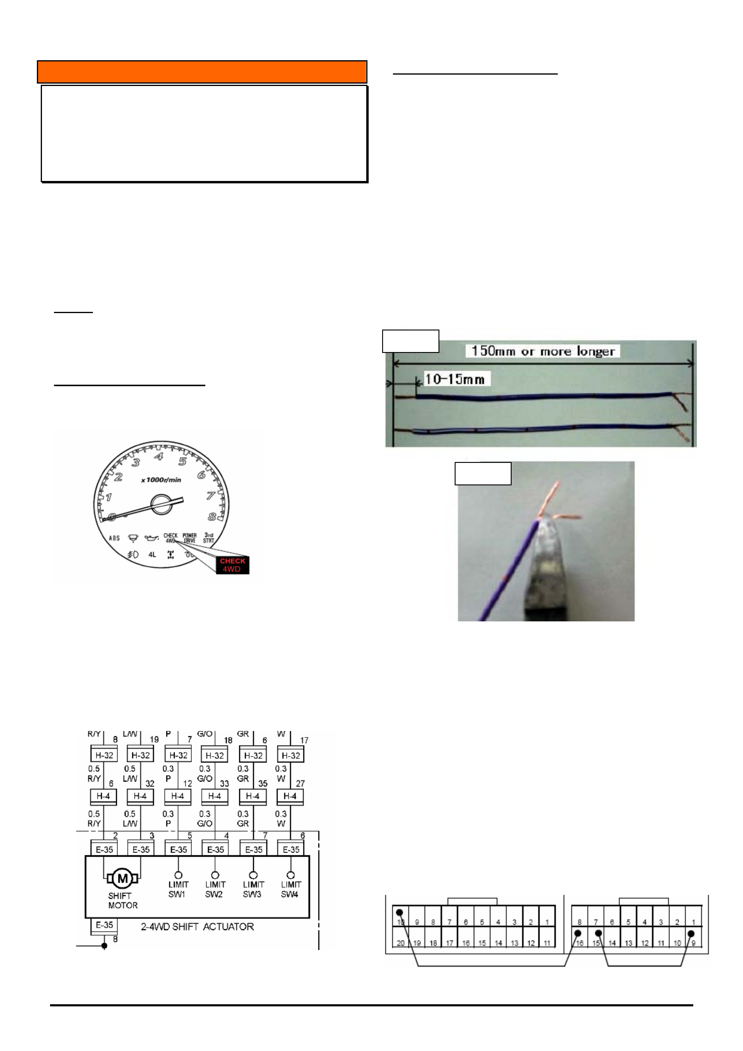
HOLDEN SERVICE TECHLINE ___________________________________________________________________________OCTOBER, 2005
6
Holden Techlines are written to inform technicians of conditions that may occur on some vehicles, and to provide information that could assist in the
proper service fix of a vehicle. If a condition is described, do not assume the service fix applies to a vehicle or that the vehicle will have that condition.
INFORMATION
Check 4WD Light Illuminated
RA Rodeo
(GROUP 8) TL0950-0509
This Techline is written to clarify the diagnostic
procedures that need to be carried out when a Check
4WD light is illuminated in RA Rodeo.
Read in conjunction with Techline No. TL0623-0402
published in Issue 2, March 2004 (revised TCCM).
NOTE:
Ensure earth points C-109, C-36, C-2, P-6, P-10, E-
10 (Diesel) are clean and tight before proceeding.
Refer LCV SIP for earth locations.
PROBLEM DESCRIPTION
Vehicle presented to workshop with the “CHECK 4WD”
light illuminated in the instrument cluster. Refer
following figure 1.
Figure 1.
The check 4WD light will illuminate if the Transfer
Case Control Module (TCCM) detects that there is a
circuit fault relating to any of the 4 limit switches in the
transfer case actuator shown in Figure 2.
NOTE: for the complete diagram refer to LCV SIP,
Section 8A Electrical body & chassis\ System repair\
Shift on Fly.
Figure 2. Extract of Circuit Diagram for 4JH1-TC.
TCCM RESET PROCEDURE
Reset the TCCM by bridging the terminals as shown
below in Figure 5. Make jumper wires as below if
required.
Prepare two jumper wires approximately 150mm or
longer with wire size - 0.5mm.
Strip the wire insulation within 10 – 15mm from each
end as shown in Fig 3.
At one end of each jumper wire, separate the stripped
wire into two halves as shown in Fig 4. This is to allow
the wire to be inserted into the small connector
cavities.
NOTE: Solder tinning of each of the two halves will
provide increased rigidity and hold the wire strands
together.
1 Turn OFF the ignition switch.
2 Disconnect the harness connector of the seat belt
switch (under drivers seat)
3 Remove the front seat assembly.
4 Spread the cut line of the floor carpet or roll up the
floor carpet.
5 Remove two bolts holding the TCCM protector
cover. Pull out the TCCM onto the carpet for access
to the connectors
6 Insert the jumper wires from the back of the
connector to bridge terminals 10 - 16 and 15 - 9 .as
shown in figure 5. Note. Terminals 15 & 16 have no
wires in connector cavity.
R14 R15
Figure 5.
Fi
g
3
Fi
g
4.
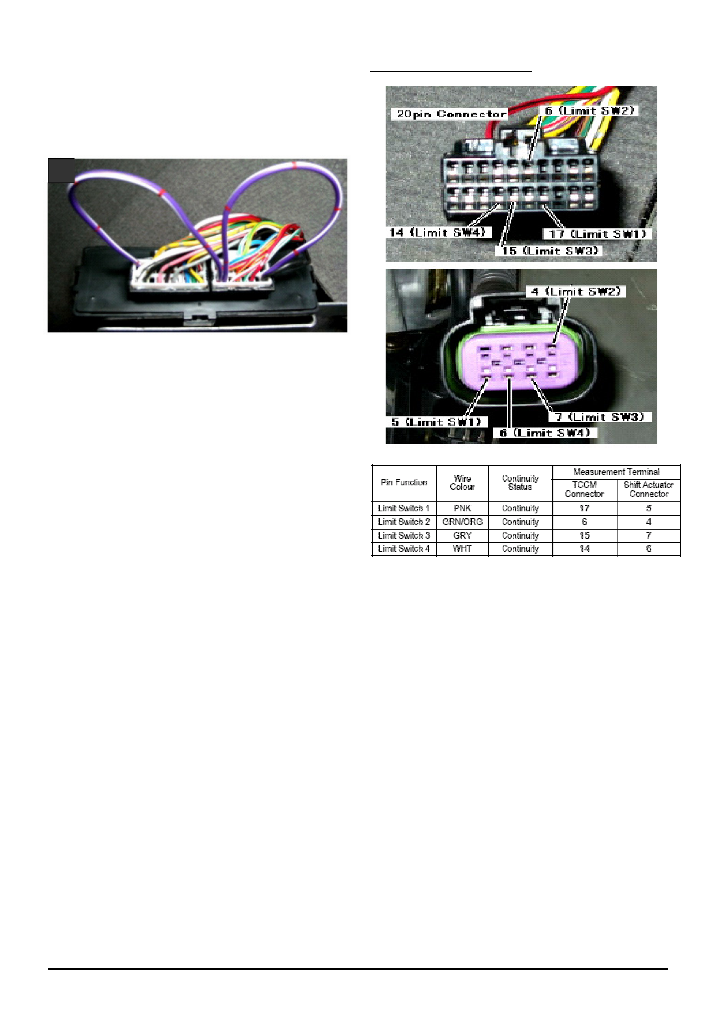
HOLDEN SERVICE TECHLINE ___________________________________________________________________________OCTOBER, 2005
7
Holden Techlines are written to inform technicians of conditions that may occur on some vehicles, and to provide information that could assist in the
proper service fix of a vehicle. If a condition is described, do not assume the service fix applies to a vehicle or that the vehicle will have that condition.
WARNING:
The jumper wires must be inserted into the correct
positions. Inadequate insertion or insertion into the
wrong positions will cause failure of the TCCM or
blowing of the ABS Fuse.
Confirm that the stripped portion of the jumper wires are
fully inserted into the connector cavities as shown.
7 Turn ON the ignition switch while watching the
Check 4WD light. It should go out.
8 Turn OFF the ignition switch and remove the
jumper-wires from the TCCM.
9 Turn ON the ignition switch again to verify the
“CHECK 4WD” indicator lamp is OFF after bulb
check process.
If the “CHECK 4WD” indicator lamp remains ON, either
the jumper wires have not contacted the TCCM
terminals correctly or the TCCM has determined there is
a limit switch position fault.
If the check 4WD light remains off, start the vehicle &
operate the 4WD switches to 4H, 4L 2H and neutral to
confirm correct 4WD operation. If Check 4WD light
remains off this shows there is no current fault with the
4WD system. Check harness & terminal connections for
intermittent faults.
If the Check 4WD light illuminates when operating the
4WD buttons, this indicates there is a fault with one of
the limit switch circuits.
Perform wiring harness checks as follows.
WIRING HARNESS CHECKS
Ensure ignition switch is OFF
Disconnect the TCCM and the Actuator connectors
(Shown Above)
Test the shift-actuator harness continuity using ohm
meter. Refer to table and photographs above for limit
switch circuits.
(Example – Probe Ohm Meter between TCCM
Connector Pin 17 and Shift Actuator Connector Pin 5 to
test Limit Switch 1)
NOTE : Ensure correct sized test terminals are used
when probing to avoid terminal damage
There should be continuity on each limit switch circuit.
Approx 1 Ohm.
Check for a short to earth on all limit switch circuits,
There should be NO Continuity to earth.
Check for a short to battery voltage on each limit switch
circuit, There should be NO short to voltage.
If any problem is found with the wiring, repair as
required.
If the fault persists, perform limit switch checks as
follows.
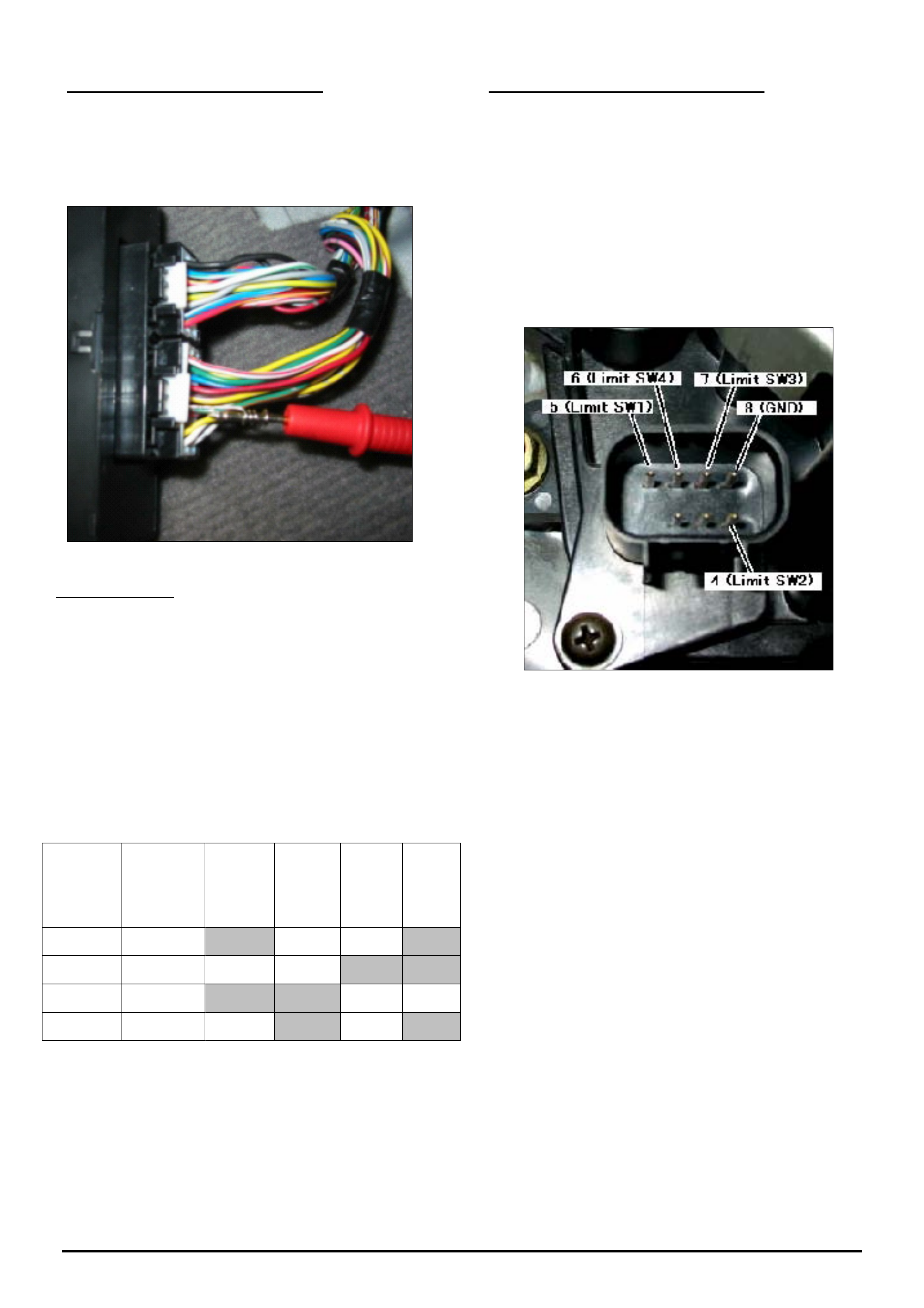
HOLDEN SERVICE TECHLINE ___________________________________________________________________________OCTOBER, 2005
8
Holden Techlines are written to inform technicians of conditions that may occur on some vehicles, and to provide information that could assist in the
proper service fix of a vehicle. If a condition is described, do not assume the service fix applies to a vehicle or that the vehicle will have that condition.
LIMIT SWITCH VOLTAGE CHECKS
Use a volt meter to check limit switch circuits
Probe the test-lead from the back of the connector
R14 as shown in the following picture.
Test Conditions:
• Ignition switch is ON.
• TCCM memory is reset & check 4WD light is off
• All connectors are connected.
Measure the output voltage between terminal
numbers 17, 6, 15, 14 in TCCM connector and earth
at each transfer case position 2H 4H N 4L using the
following table.
CLOSED POSITION = 0 V DC
OPEN POSITION = 12 V DC
Terminal
Nos. in
R14
connector
Shift
Actuator
Pin
2H 4H N 4L
17 LS1 Closed Open Open Closed
6 LS2 Open Open Closed Closed
15 LS3 Closed Closed Open Open
14 LS4 Open Closed Open Closed
(refer Figure 5 for location of terminals 17,6,15,14)
If a fault is found, perform the following limit switch
continuity checks.
LIMIT SWITCH CONTINUITY CHECKS
The limit switch continuity can be checked using an
Ohm Meter and the following table shown in Figure 6.
NOTE: The actuator must be connected & electrically
driven to each position & then the connector must be
disconnected to do continuity checks.
NOTE: Only connect & disconnect the connector on
the actuator with the ignition switch in the off position
or TCCM lock up will occur
If no continuity is measured with any of the 4 limit
switches then the fault is internal in the shift actuator,
in this case replace the shift actuator

HOLDEN SERVICE TECHLINE ___________________________________________________________________________OCTOBER, 2005
9
Holden Techlines are written to inform technicians of conditions that may occur on some vehicles, and to provide information that could assist in the
proper service fix of a vehicle. If a condition is described, do not assume the service fix applies to a vehicle or that the vehicle will have that condition.
Continuity Status at each Transfer Position
Connector
Terminal No.
Pin
Function
2H
4H
4L
Neutral
Measurement
Terminal
5 Limit
Switch 1
Continuity Non
Continuity
Continuit
y
Non
Continuity
5 & 8
4 Limit
Switch 2
Non
Continuity
Non
Continuity
Continuit
y
Continuit
y
4 & 8
7 Limit
Switch 3
Continuity Continuity Non
Continuity
Non
Continuity
7 & 8
6 Limit
Switch 4
Non
Continuity
Continuity Continuit
y
Non
Continuity
6 & 8
Figure 6.

HOLDEN SERVICE TECHLINE ___________________________________________________________________________OCTOBER, 2005
10
Holden Techlines are written to inform technicians of conditions that may occur on some vehicles, and to provide information that could assist in the
proper service fix of a vehicle. If a condition is described, do not assume the service fix applies to a vehicle or that the vehicle will have that condition.
INFORMATION
Requesting Immobiliser Security Codes
All Models
(GROUP OB) TL0936-0509
Many Dealers request immobiliser security numbers
from the Holden Vehicle Security Information Centre
for vehicles that don’t have an immobiliser or don’t
require an immobiliser number. Refer to the
following examples.
• Some variants of SB Barina, TR Astra, TF Rodeo,
and UT and MX Frontera’s do not have an
immobiliser fitted.
• VZ & WL Gen 3 vehicles have a BCM security
number but do not have an immobiliser security
number. Note that VZ & WL V6 vehicles require
an immobiliser security number.
• All YG Cruze’s require an immobiliser and BCM
number and these can be found in LCRV SIP.
As you can see from these examples, it is important
to ensure that the vehicle you are requesting security
information for actually has an immobiliser or
requires an immobiliser number.
It is therefore recommended that you check the
available Service Information for location of
components.
New Procedure For Obtaining Security Numbers.
(The following information is extracted from All
Dealer Letter 42/05 dated 19 Sep,2005.)
To obtain an immobiliser security number you MUST
FIRST check on-line via the NOW warranty system
for the information.
If the security information is not available via the
NOW system or a specific security number is not
working on a vehicle, Dealers need to fax Holden a
revised security information request form (copy on
Lionheart). It is mandatory that all fields on the form
are completed, including reference to any security
information obtained from the NOW system.
It is important to note that Holden will not be
processing security information requests that are
incomplete or on the old form. Please discard any
earlier versions of the form. Dealers are also
reminded not to fax multiple requests for the same
vehicle VIN.
Please note that TAS do not process requests for
Security Codes.
Also, there is a revised “Vehicle Security Information
Change Advice” form (copy on Lionheart). Dealers
should use this form to advise Holden of any
changes to a vehicle’s security information.
INFORMATION
Rear Limited Slip Differential Operation –
Driving Hint
RA Rodeo, UBS Jackaroo
Group 4 Ref. No. TL0995 - 0509
CONDITION
Some owners have reported that when their vehicle
lost rear wheel traction they noticed that only one
wheel was spinning. This caused them to think that the
LSD was not operating correctly.
In these cases it is most likely that the differential is
operating correctly and only requires some Torque
Reaction to activate the LSD.
The LSD Driving Hint shown below is a simple method
which the driver can use in the above situation to
activate the LSD. This hint is extracted from a Techline
published in July 2000, which described the operation
of Limited Slip Differentials as fitted to Jackaroo and
Rodeo. The Techline may still be referred to by going
to the Holden Dealer Portal website “Lionheart”.
Please provide this LSD Driving Hint to any customer
who believes there is something wrong with the LSD in
their vehicle.
LSD Driving Hints
All the LSD designs described rely on the separating
force between the pinion and side gears to operate
effectively.
If the vehicle is operated in extreme conditions and
single wheel spin is evident without forward motion,
then the gear separating force can be increased by
applying the hand brake. This technique can be used
to increase the clutch clamping force on any LSD, but
it is extremely effective to engage an LSD that has no
pre-load springs.
Caution
The hand brake needs to be applied gradually while
maintaining power for this technique to work
successfully and should only be used to free the
vehicle from the obstacle that is preventing forward
motion. Once the vehicle is driven clear of the
obstacle, the hand brake should be released to
prevent damage to the hand brake linings.
IMPORTANT: Do Not Replace or Repair
Differentials For The Above Condition.
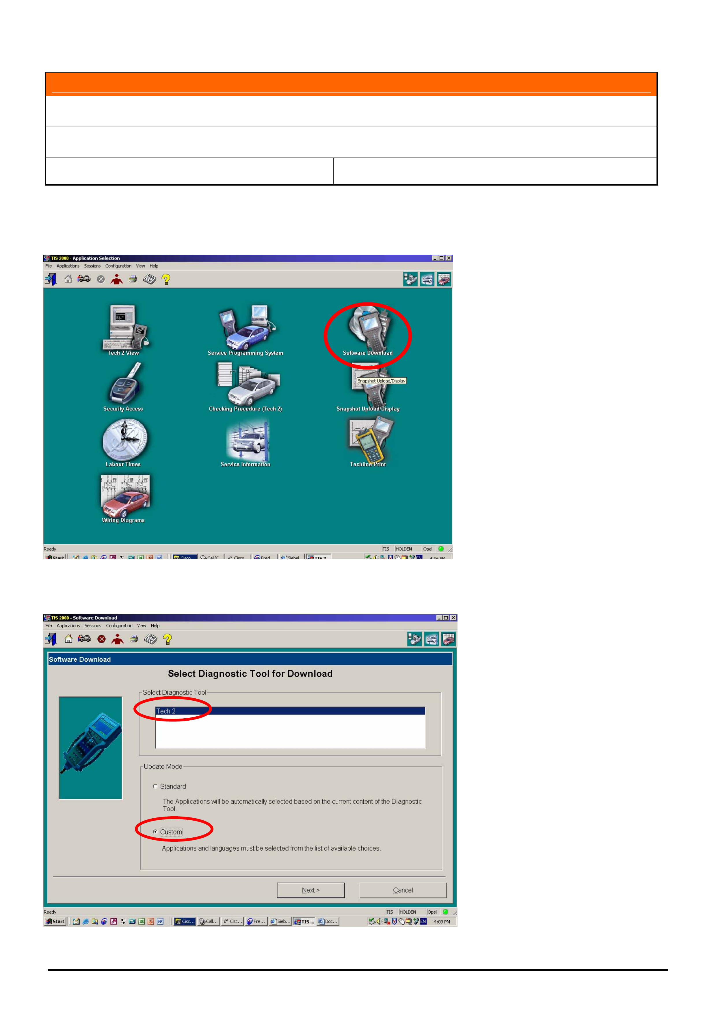
HOLDEN SERVICE TECHLINE ___________________________________________________________________________OCTOBER, 2005
11
Holden Techlines are written to inform technicians of conditions that may occur on some vehicles, and to provide information that could assist in the
proper service fix of a vehicle. If a condition is described, do not assume the service fix applies to a vehicle or that the vehicle will have that condition.
INFORMATION
Tech 2 Custom Downloads
All
Group OB Ref. No. TL0999 - 0509
At times service departments may need to use TIS 2000 to change Tech 2 software to an earlier version.
The following instructions detail the correct procedure to do this.
1.From the TIS 2000 main menu select Software Download
2. Select “Tech 2” from the upper menu and “Custom” from the lower menu.
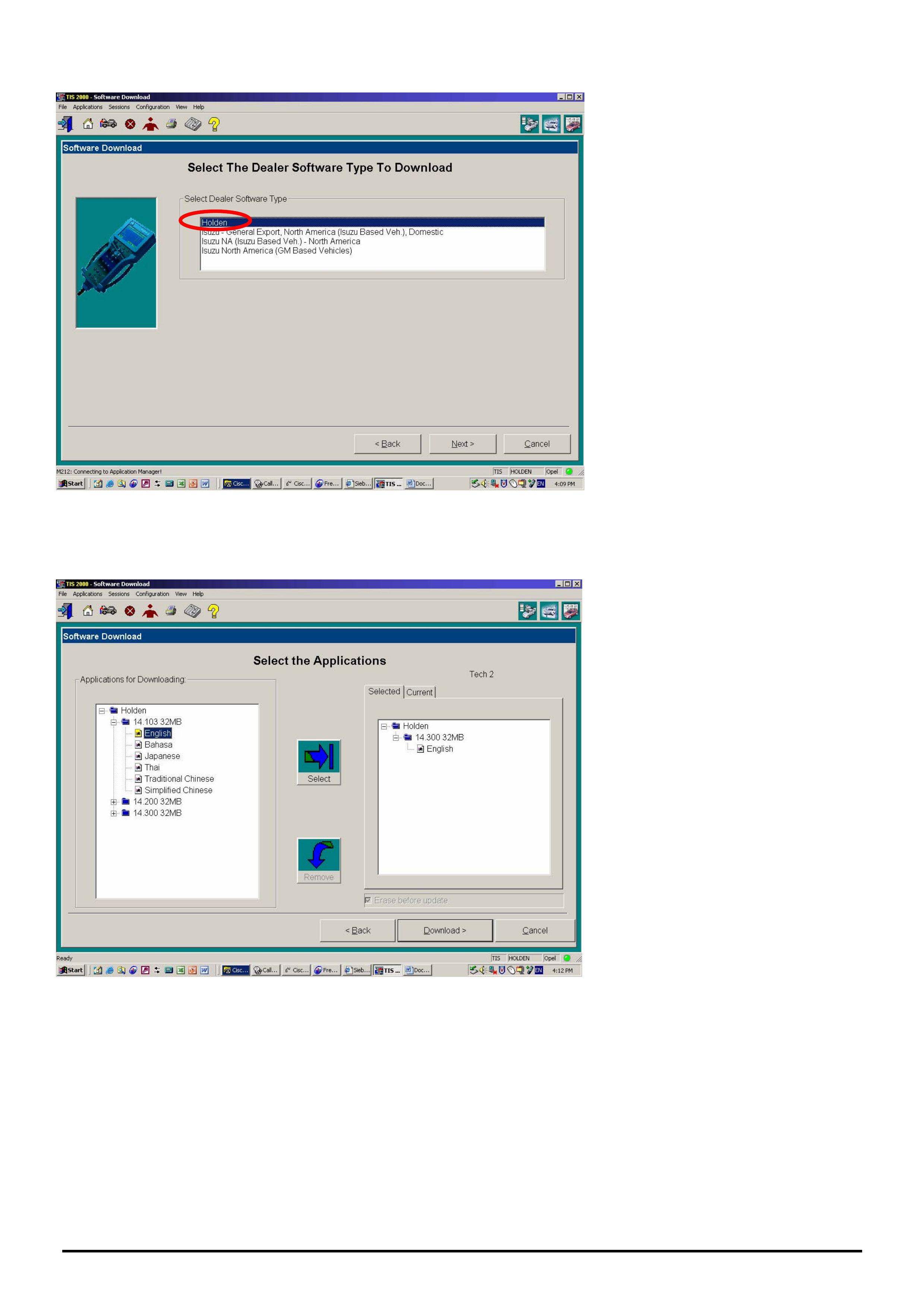
HOLDEN SERVICE TECHLINE ___________________________________________________________________________OCTOBER, 2005
12
Holden Techlines are written to inform technicians of conditions that may occur on some vehicles, and to provide information that could assist in the
proper service fix of a vehicle. If a condition is described, do not assume the service fix applies to a vehicle or that the vehicle will have that condition.
3. Select Holden
When presented with the above screen, from the Applications for Downloading area, select the version and language
you wish to download. Once highlighted, press the Select button. The detail of what will be downloaded will now
appear on the right of the screen. If the details are correct Select download.
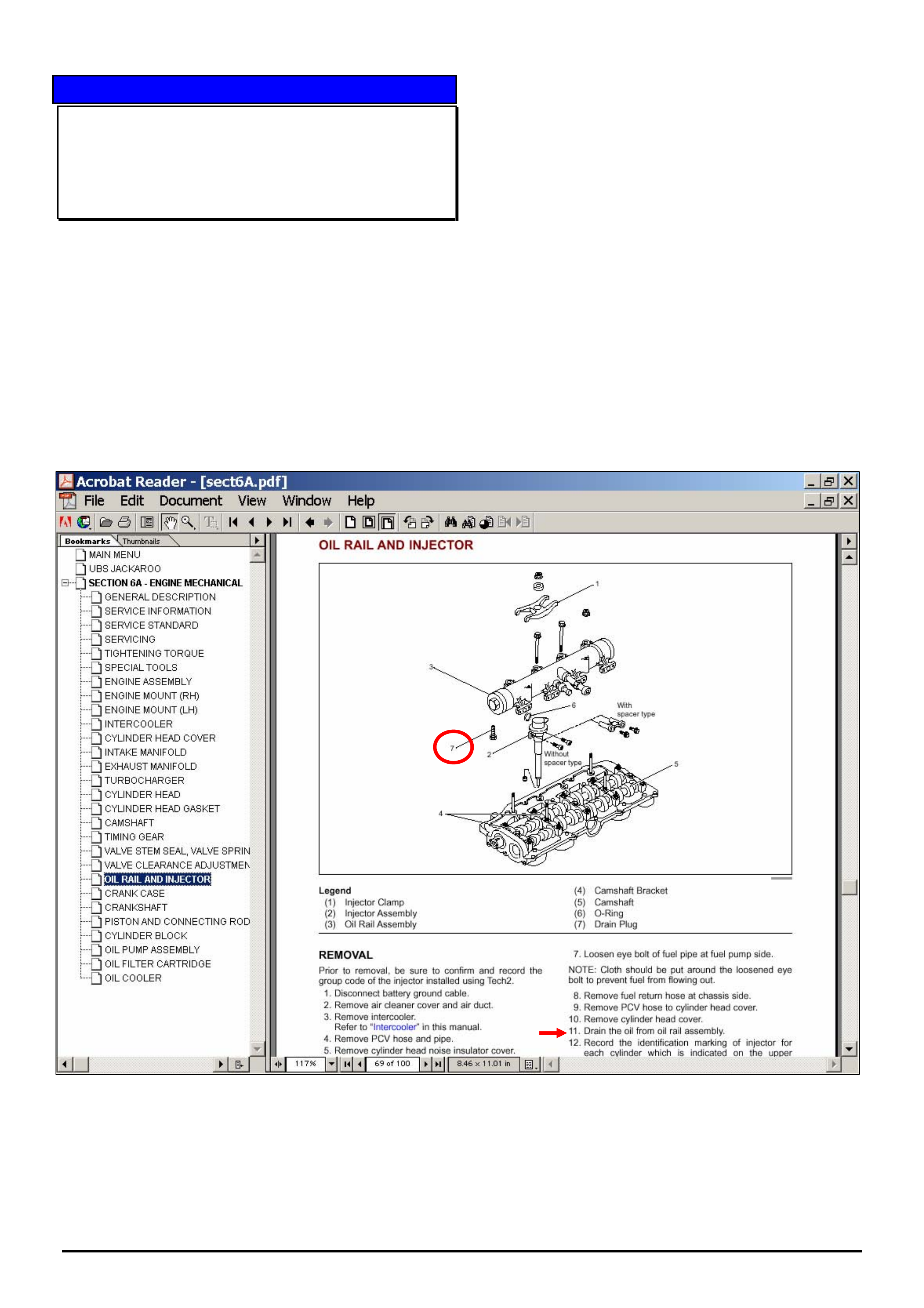
HOLDEN SERVICE TECHLINES___________________________________________________________________________NOVEMBER, 2005
9
Holden Techlines are written to inform technicians of conditions that may occur on some vehicles, and to provide information that could assist in the
proper service fix of a vehicle. If a condition is described, do not assume the service fix applies to a vehicle or that the vehicle will have that condition.
SERVICE PROCEDURE
Oil Rail Draining Procedure
UBS Jackaroo with 4JX1 Diesel engine
(GROUP 6A) TL1012-0510
To avoid oil loss / spillage when removing injectors for
service related operations e.g. valve clearances, it is
necessary to follow the removal procedure in LCV SIP.
Pay particular attention to Step 11 which states:-
“Drain the Oil from Oil Rail Assembly”. This is achieved
by removing the drain plug with a 19mm spanner. The
drain plug is shown in figure below. Refer item 7.
CAUTION. If the engine is hot, the oil exiting the rail
may be extremely hot.
NOTE:
1. The drain plug is fitted with an O-ring seal.
2. The tightening torque for the drain plug is missing
from LCV SIP. The Drain Plug Torque Specification is
24.5 Nm+/- 5.0 Nm (2.5 +/-0.5 kgm)
The information in LCRV SIP will be updated in a
future issue,.
DRAIN PLUG

HOLDEN SERVICE TECHLINES___________________________________________________________________________NOVEMBER, 2005
17
Holden Techlines are written to inform technicians of conditions that may occur on some vehicles, and to provide information that could assist in the
proper service fix of a vehicle. If a condition is described, do not assume the service fix applies to a vehicle or that the vehicle will have that condition.
DIAGNOSIS HINT
Cracked Flex Plate Caused By Missing Dowel
Pins
RA Rodeo with Auto. Trans
Group 7B Ref. No. TL1014 - 0510
CONDITION
Vehicles may be presented with a rattle noise from the
rear of engine which after investigation is found to be
caused by a cracked flex plate.
In some instances the vehicle is returned a second time
with a repeat failure of the flex plate.
In almost all cases, the vehicle has previously
undergone engine or transmission repairs/ replacement
prior to flex plate failure.
RECOMMENDATION
If the locating dowels that are normally fitted in the
engine block to transmission mating surface are
missing, then misalignment of the engine and
transmission can occur. This places stress on the flex
plate and torque converter and will result in cracking of
the flex plate.
Technicians need to ensure that when repairing an
engine or transmission that the dowels do not pull out
of the engine block.
Also, when fitting a new engine, ensure that the dowels
are swapped from the replaced engine if not already
fitted to the new engine.
SERVICE PROCEDURE
Flywheel Timing Procedure
UBS Jackaroo 4JX1 Diesel
Group 6A Ref. No. TL1026 - 0510
Technicians are reminded that when engine or clutch
repair is carried out on the Jackaroo Diesel 4JX1
engine, the flywheel must be timed to the crankshaft
or the engine will not run.
This procedure is found in LCV SIP as follows: -
Service Information / UBS Jackaroo / Engine 4JX1 / 6A
Engine Mechanical / Crankshaft .
There is also a hyperlink to the previous techline on this
subject.
INFORMATION
Ethanol Fuel Usability
All Post - 1986 Holden Vehicles
Group 6M Ref. No. TL1011 - 0510
The information shown below is taken from the Holden
website (www.holden.com.au). Customers can be referred
to the website for additional information should there be
any need.
Holden vehicles manufactured since 1986 will operate
satisfactorily on Ethanol fuel blend “E10”, with the
exception of the following vehicles that do not operate
satisfactorily on E10 fuel:
Apollo (1/87 - 7/89),
Nova (2/89 - 7/94),
Barina (1985 - 1994),
Drover (1985 - 1987),
Scurry (1985 - 1986),
Astra (1984 - 1989).
Owners of these vehicles should refer to the vehicle's
Owner's Manual for recommended fuel usage.
Purchasing fuel
When purchasing fuel, Holden recommends that
vehicles are operated on fuel containing no more than
10% ethanol.
Purchasing your fuel from a reputable retailer may
reduce the risk of purchasing fuel containing more than
10% ethanol or other abnormal properties. Under no
circumstances should you use fuel containing more
than 10% ethanol.
Use of such fuels may result in engine malfunction,
starting and operating difficulties, and materials
degradation. These adverse effects could result in
permanent damage to your vehicle.
It is also important to note that when ethanol blends
are used, fuel consumption can be expected to
increase due to the lower energy content of ethanol. It
is important to note the use of any fuel, other than the
fuel specified in the vehicle's Owner's Manual, may
seriously damage your vehicle and may void your
Warranty. Only good quality, clean fuel should be
used.
The use of fuel containing more than 10% ethanol may
also affect your New Vehicle Warranty.
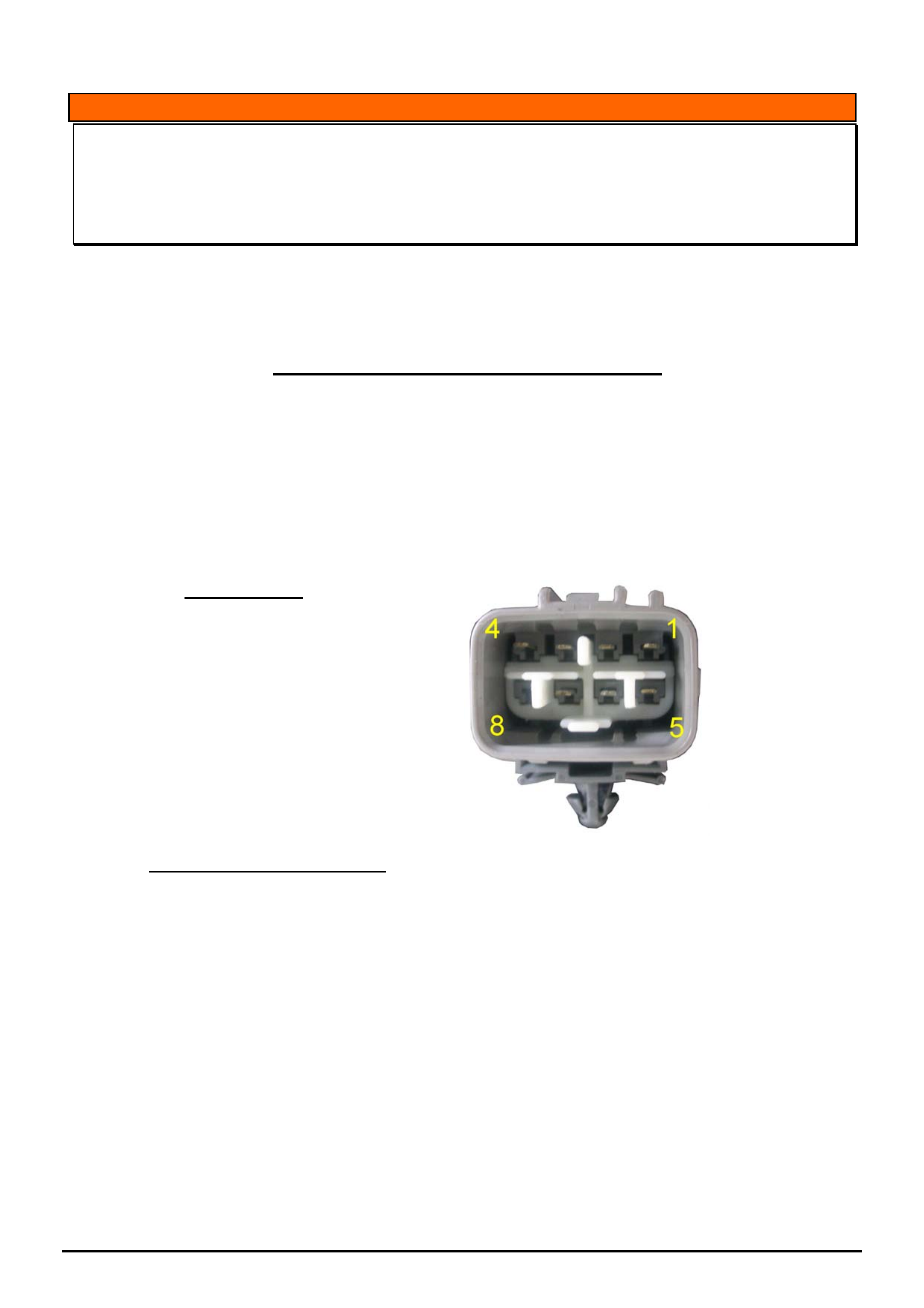
HOLDEN SERVICE TECHLINES___________________________________________________________________________NOVEMBER, 2005
18
Holden Techlines are written to inform technicians of conditions that may occur on some vehicles, and to provide information that could assist in the
proper service fix of a vehicle. If a condition is described, do not assume the service fix applies to a vehicle or that the vehicle will have that condition.
INFORMATION
Towbar Harness Breakout Revision
RA Rodeo Fitted With Genuine Accessory Tow Bar
(GROUP 12 ) TL1023-0510
The vehicle harness breakout connector for the RA Rodeo trailer harness has been changed from a six pin
connector to an eight pin connector on some vehicles. This change is detailed in HSPO Parts Techline PT189
and is repeated below.
Parts Techline- PT189 - dated 27th Sep 2005.
The vehicle harness breakout connector for the RA Rodeo trailer harness has been changed from a six pin
connector to an eight pin connector on some vehicles. If the vehicle has an eight pin connector an adaptor
harness will be required (P/N 92189211). There is limited stock of these parts as the supplier ramps up
production.
If you have a vehicle that is required for urgent delivery it is possible to hard wire the trailer harness using the
following circuit identification as a guide.
In the future, the trailer harness will not be supplied in the towbar kit, and the patch harness will be
superseded with a unique harness for the 8 pin connector with extra functionality. There will be a bulletin
announcing this change.
8 Pin Connector
Terminal Wire Colour Circuit
1 Black Reverse
2 Red Brake
3 Brown Tail Light
4 Pink Power
5 White Earth
6 Green RH Indicator
7 Yellow LH Indicator
8 Not Used
6 Pin Trailer Harness Connector
Terminal Wire Colour Circuit
1 Brown Tail Light
2 Red Brake
3 Black Reverse
4 White Earth
5 Green RH Indicator
6 Yellow LH Indicator

HOLDEN SERVICE TECHLINES___________________________________________________________________________NOVEMBER, 2005
21
Holden Techlines are written to inform technicians of conditions that may occur on some vehicles, and to provide information that could assist in the
proper service fix of a vehicle. If a condition is described, do not assume the service fix applies to a vehicle or that the vehicle will have that condition.
SERVICE FIX
Manual Transmission Rattle Noise in Neutral
at Idle
RA 4JH1 Diesel with M/T
Group 7A Ref. No. TL0910A-0510
This Techline supercedes TL0910-0504 in Issue 4, May,
2005. It is updated by adding service fix information.
CONDITION
The vehicle may develop a “rattle” or “chatter” type noise
from the gearbox area when the engine is at idle and the
gearbox is in neutral and foot is off the clutch pedal.
The noise will stop under any one of the following
conditions:
• when vehicle is driven.
• when engine idle RPM is increased.
• when the clutch pedal is depressed.
The noise may be intermittent.
CAUSE
A worn clutch disc centre bush reduces the
effectiveness of the clutch disc to dampen out the
fluctuations in engine revs and noise from the
engagement of transmission gear teeth. The end result
is a rattling noise.
CORRECTION - Service
If a vehicle is presented with the above complaint,
replace the clutch plate with new plate p/n
8979442770. (Improved bush material).
CORRECTION – Production
Revised clutch plates are scheduled for fitment in
production from mid November. When a breakpoint is
established it will be advised in a future Breakpoint
Summary.
PARTS INFORMATION
Part No.: Name Qty:
8979442770 Disc - Clutch 1
WARRANTY CLAIM INFORMATION
Use Labour Times information in Warranty Information
section of current PV SIP CD
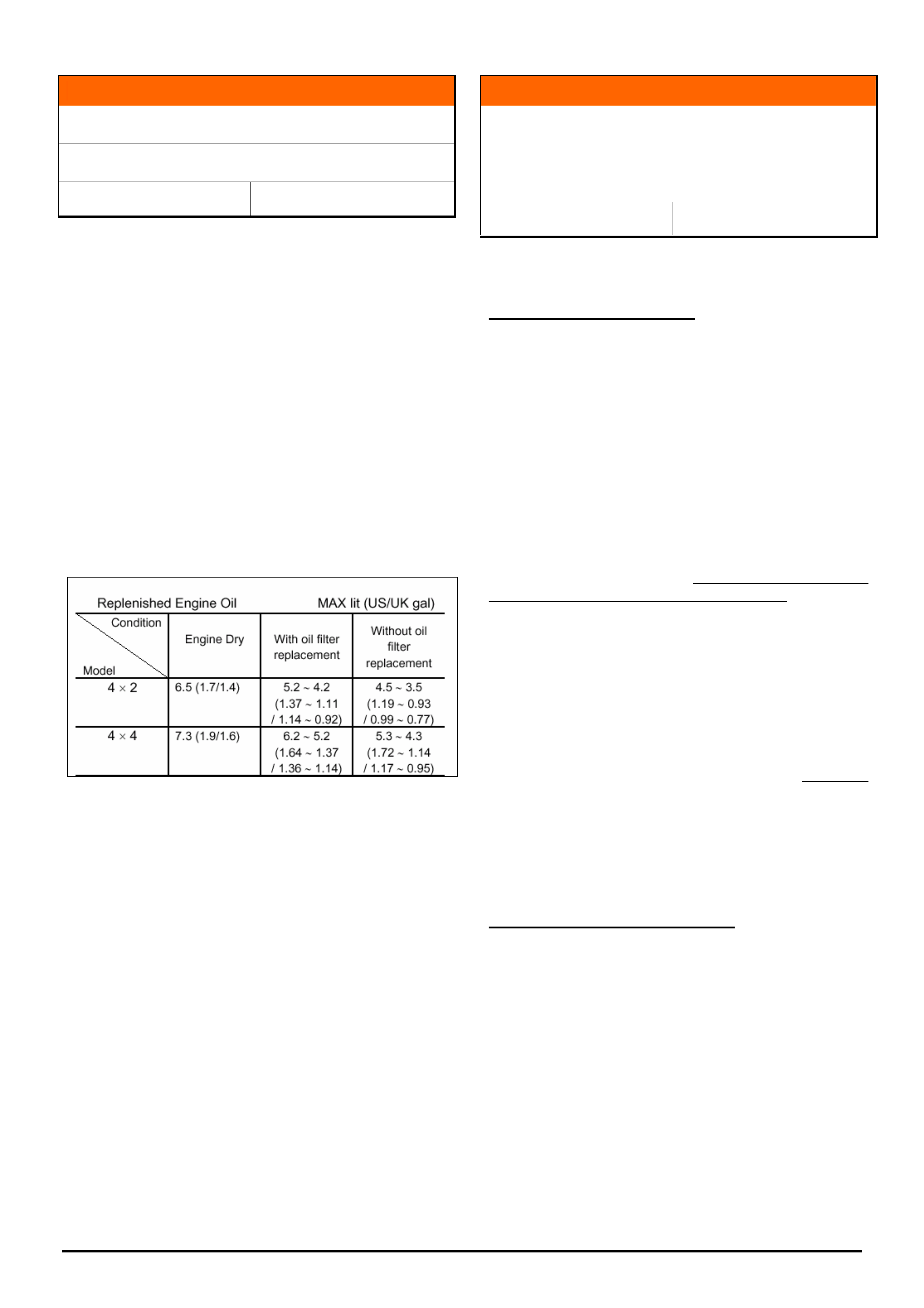
HOLDEN SERVICE TECHLINES___________________________________________________________________________DECEMBER, 2005
7
Holden Techlines are written to inform technicians of conditions that may occur on some vehicles, and to provide information that could assist in the
proper service fix of a vehicle. If a condition is described, do not assume the service fix applies to a vehicle or that the vehicle will have that condition.
INFORMATION
Oil Refill Capacity
TF & RA Rodeo – 4JH1 TC
Group 6A Ref. No. TL1055-0511
Dealers should be aware that the engine oil capacities
specified in the owner’s handbook are “dry fill”
specifications.
Due to the amount of residual oil held in the turbo
galleries and oil cooler, replenishing with the “dry fill”
capacity can lead to an over fill situation.
Engine over fill can lead to excessive oil ingestion
through the PCV system which, in an extreme case,
could lead to engine damage.
Engine oil service capacities are published in SIP
under
6A – Engine Mechanical – Servicing – Lubricating
System as shown below.
INFORMATION
Seat Belts Replaced For Complaint Of Not
Extending
UES Frontera, YG Cruze, RA Rodeo
Group 1 Ref. No. TL0253A – 0511
This Techline is repeated as dealers continue to replace seat
belts for this condition which is not a fault.
PROBLEM DESCRIPTION
Numerous seat belts returned through the warranty
system cannot be faulted. The reason for replacement
of these belts is given as "seat belt will not extend" or
"seat belt jamming".
It appears that customers and Dealer staff may be
unaware of the Auto Locking Ratchet (ALR) system.
Refer to following for an explanation of ALR.
Automatic Locking Ratchet (ALR) Mechanism.
The rear outer seat belts (all rears on RA Rodeo) and
left hand front seat belt have an Automatic Locking
Ratchet (ALR) mechanism. When this mechanism is
activated it will only allow the belt to retract. When the
mechanism is de-activated the belt can be extended or
retracted as normal.
To activate the ALR mechanism, extend the seat belt
to its maximum length.
To de-activate the ALR mechanism, allow the seat
belt to retract fully.
The ALR function may be useful as an additional
means of locating a child seat, when used in
conjunction with the approved child restraint anchor
points.
NOTE: It is always better to install a child restraint in
the rear seat.
SERVICE RECOMMENDATION
To avoid mis-diagnosis of seat belts, Holden Dealer
frontline staff should familiarise themselves with the
operation of the ALR system . They will then be able
to explain this feature to any customers who complain
that their seat belts “will not extend” or are “jamming”
whilst driving.
NOTE: Seat belts replaced unnecessarily for complaint
of “not extending” will not be accepted as warranty.

HOLDEN SERVICE TECHLINES___________________________________________________________________________DECEMBER, 2005
8
Holden Techlines are written to inform technicians of conditions that may occur on some vehicles, and to provide information that could assist in the
proper service fix of a vehicle. If a condition is described, do not assume the service fix applies to a vehicle or that the vehicle will have that condition.
DIAGNOSIS HINT
DTC P0107 – MAP Sensor Circuit Low Voltage
UBS 4JX1
Group 6C Ref. No. TL1051 - 0511
CONDITION
This hint applies to vehicles that have DTC P0107
(MAP Sensor Circuit Low Voltage) stored as present or
not present and, the MAP sensor is reading lower than
typical scan values (96 – 106 KPa).
Low manifold pressure can be caused by excessive
carbon sludge build up in the throttle valve assembly.
Where excessive sludge build up is identified, remove
the throttle body assembly and clean.
Note: Do not submerse the throttle body assembly in
any type of fluid.
Do not spray flammable fluid into the intake manifold.
INFORMATION
Fuel Filler Neck Modification Required on New
Vehicles Being Fitted With a Tray
RA Rodeo Long Wheelbase with Petrol engine
Group OB Ref. No. TL1035-0511
ATTENTION SERVICE MANAGERS.
The following information must be relayed to your New
Car Sales People.
All new petrol engine RA Rodeo Long wheelbase
models (with the letter “H” in ISOVIN as shown below),
where the ute body has been removed and replaced
with a tray, must have the fuel filler neck replaced as
per the instructions given in Holden Campaign Bulletin
05-H-05, Page 3, Action “B”.
Models affected are identified by letter H (9th digit) as
shown.
MPATFR26H3T1000020
The parts required for this action are listed below and
are to be purchased from HSPO except for the bracket
which is purchased from Triple M.
Part No.: Description: Qty
8979434450 Hose-Fuel Filler Neck 1
8979426620 Neck – Fuel Filler 1
8973647110 Cap – Fuel Filler Locking 1
92187018 Fuel filler flap label 1
9PECK305 Bracket kit 1
NOTE: The cost for this work is Retail, not Warranty.
DIAGNOSIS HINT
Noise From Steering (Tie Rod Inner Ball Joint
Wear)
RA Rodeo
Group 9 Ref. No. TL1030-0511
Investigation of steering gear assemblies returned for
complaint of noise, has found that most of them have
worn inner tie rod assemblies which could have been
replaced separately.
When diagnosing the complaint, some dealers
automatically assume there is a problem within the
steering rack and therefore replace the steering gear
assembly.
SERVICE RECOMMENDATION
DO NOT AUTOMATICALLY REPLACE THE
STEERING GEAR ASSEMBLY.
The first step should be to check the tie rod assembly
for excessive wear, paying particular attention to the
inner ball joint. Replace worn parts as required.
Refer to procedure in LCRV SIP Section 3B-Power
Assisted Steering System, Power Steering Unit,
Disassembly & Inspection & Repair.
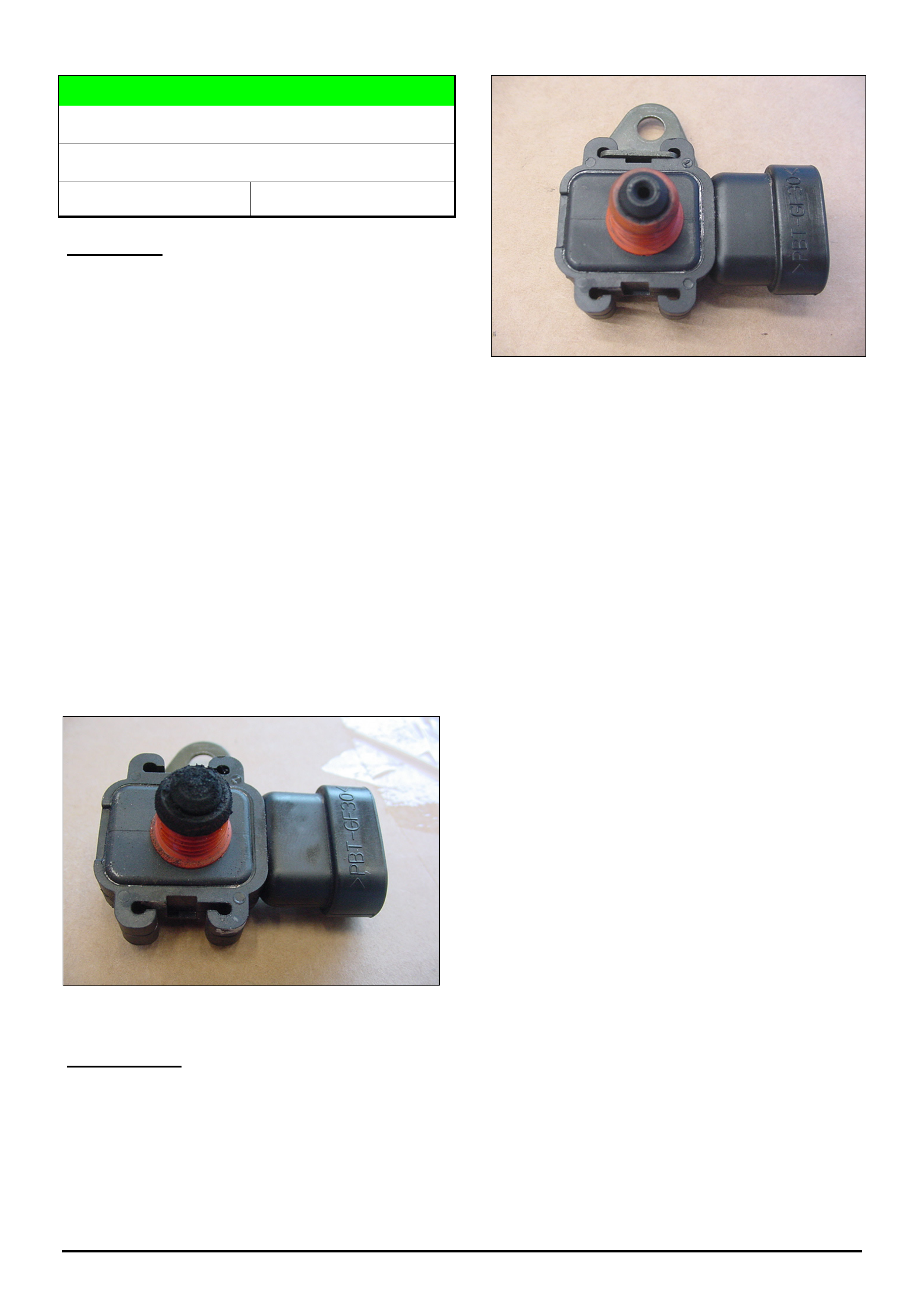
HOLDEN SERVICE TECHLINES___________________________________________________________________________DECEMBER, 2005
10
Holden Techlines are written to inform technicians of conditions that may occur on some vehicles, and to provide information that could assist in the
proper service fix of a vehicle. If a condition is described, do not assume the service fix applies to a vehicle or that the vehicle will have that condition.
DIAGNOSIS HINT
MAP Sensor Blocked With Carbon
UBS - 4JX1
Group 6C Ref. No. TL1046 - 0511
CONDITION
Vehicles with a blocked MAP sensor may exhibit one
or more or the following conditions:
• Flat spot
• Blowing Black Smoke
• Tech 2 shows insufficient manifold boost pressure.
• MAP sensor is slow to respond when viewed
through Tech 2.
The above conditions can vary with change in vehicle
operating temperature.
Due to easy accessibility, inspecting the MAP sensor for
blockage may be easier than diagnosing through Tech
2. Typical blockage is shown in Figure 1.
Note 1: Inspecting for MAP sensor for blockage does
not confirm that the MAP sensor or sensor circuit are
OK. This should be considered if further diagnostics are
required.
Note 2: MAP sensor blockage can result in driveability
symptoms that could be easily mistaken for a sticking
rail pressure control valve (RPCV) or sticking throttle
valve.
Figure 1. MAP sensor blocked with carbon (Euro III
Sensor Shown)
CORRECTION
Clean the built up carbon from the MAP sensor
breather hole. Gently scrape the carbon build up from
the breather hole while holding the sensor in a position
that allows the carbon to fall out of the sensor. Avoid
pushing carbon into the sensor.
Note: Do not use flammable cleaners on the sensor or
in the manifold.
Figure 2. MAP Sensor After Cleaning
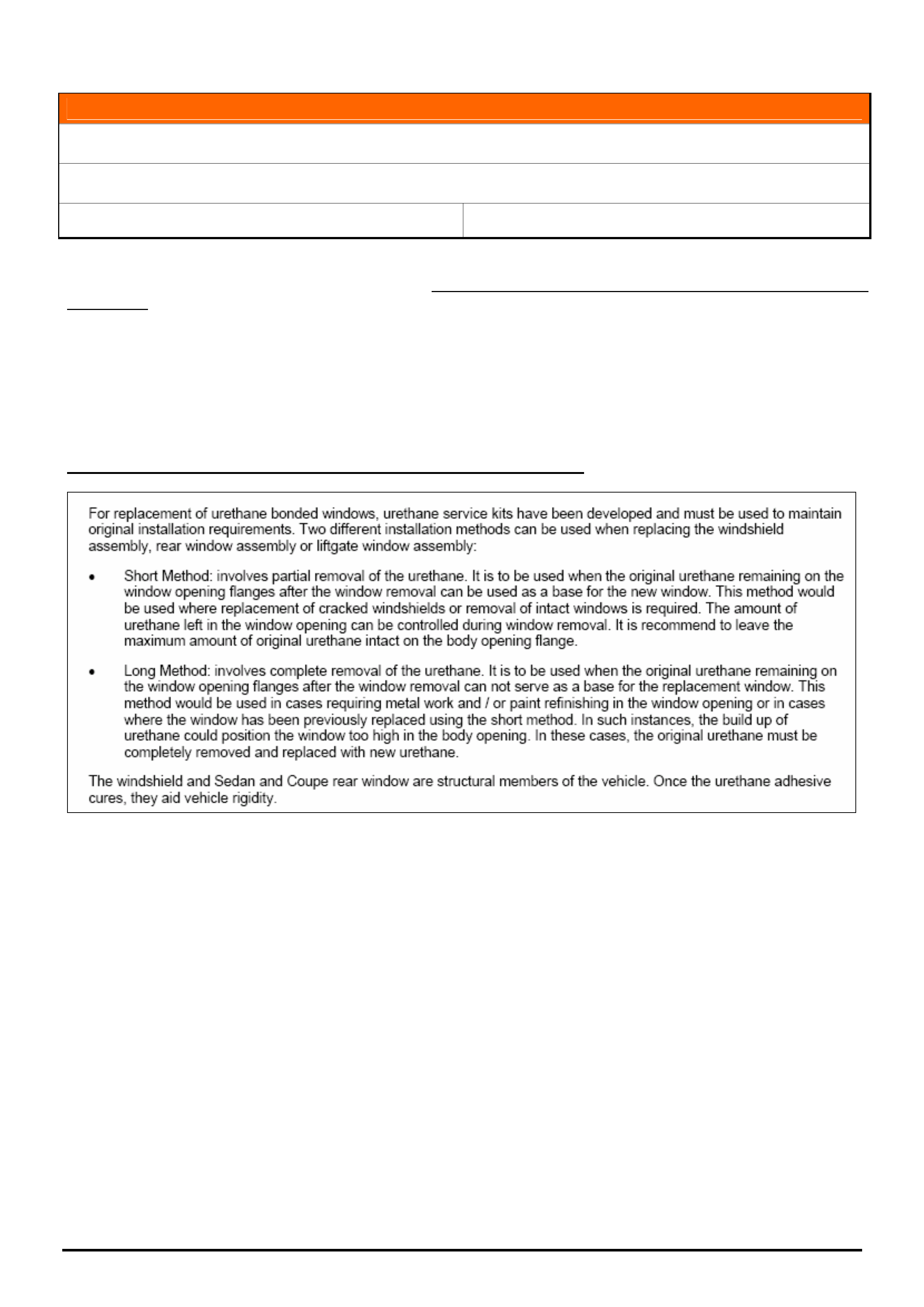
HOLDEN SERVICE TECHLINES___________________________________________________________________________DECEMBER, 2005
11
Holden Techlines are written to inform technicians of conditions that may occur on some vehicles, and to provide information that could assist in the
proper service fix of a vehicle. If a condition is described, do not assume the service fix applies to a vehicle or that the vehicle will have that condition.
INFORMATION
Use of Correct Adhesives For Fixed Glass
All Vehicles
Group 1 Ref. No. TL1002 - 0511
Dealers should be aware of the importance of using the correct adhesive when replacing (or subletting the
replacement of) fixed glass windows in any vehicle. Use of an incorrect adhesive could affect the structural integrity
of the body.
Below is an example extracted from Passenger Vehicle SIP, explaining some of the requirements when replacing
fixed glass. Refer to SIP for a full description of service procedures and requirements.
Please provide a copy of the relevant SIP procedure to your sublet repairer to comply with when installing fixed
glass.
PV SIP - Section 6A1 Stationary Windows – General Information
HOLDEN SERVICE TECHLINES___________________________________________________________________________DECEMBER, 2005
19
Holden Techlines are written to inform technicians of conditions that may occur on some vehicles, and to provide information that could assist in the
proper service fix of a vehicle. If a condition is described, do not assume the service fix applies to a vehicle or that the vehicle will have that condition.
SERVICE PROCEDURE
Oil Consumption - Catalytic Converter
Replacement
RA with V6 Engine
Group 6A & 8 Ref. No. TL0993 - 0511
The following information is provided as guidelines for
“excessive oil consumption” complaints.
When rebuilding or replacing any engine for oil
consumption, also replace the front engine
pipes/catalytic converters. The combination of oil
contamination plus rich fuel usage may cause catalytic
converter internal damage and break-up, leading to
converter material entering the engine via the EGR
and/or reverse exhaust back pressure.
For this reason – it is also of prime importance when
rebuilding or replacing an engine that the inlet manifold
is dismantled and cleaned out to ensure any debris,
converter material, etc, is completely removed.
On initial complaint – confirm oil usage rate by placing
the vehicle on an oil consumption survey (using the
standard form from SIP).
If oil consumption is:
less than 2.5 litres in 10,000 kms – No action is
necessary.
greater than 2.5 litres in 10,000 kms – investigate the
cause using the breakpoints below.
Breakpoint Reference Information:
Revised Valve Stem Seals, Isuzu 6VD1, 6VE1 V6
Engine:
Engine No.: Built Date:
152076 04/09/03
Revised Pistons & Rings, Isuzu 6VD1, 6VE1 V6
Engine:
Engine No.: Built Date:
187110 18/08/03
Warranty Claim Reference Information:
Should it be determined (by extreme oil usage and/or
bore wear or other significant defect) that engine
replacement is necessary – replace the engine using
the available “long block” p/n 8973713550 from HSPO.
This “long block” is a complete long motor less
manifolds, electrical ancillaries and harness, PCM, etc.
When fitting a “long block” – refer to Warranty
Processing letter WD 21/05 - “Revised Standard Time
for 6VE1 Engine Replacement” – that introduces new
Labour Operation Numbers for “long block” R & R.
DIAGNOSIS HINT
Preliminary Checks for Complaint of Low
Power
RA Rodeo with 4JH1 diesel engine
Group 6C Ref. No. TL1056-0511
If an owner has concerns of low power output from
their vehicle, validate the customer concern and
determine if the vehicle is, or isn’t operating normally.
If the vehicle is low on power, and before calling TAS
do strategy based diagnosis with particular emphasis
on the following items .
• Air intake system. Check for partial restriction.
Check air element and Pre-cleaner if fitted and all
ducting.
• Earth points. Clean and check C-2, C-109, P-6
and E-10. Refer to LCV SIP for locations.
• Fuel supply – fuel filter and gauze strainer in Banjo
Bolt (inlet hose of Injector Pump), Water trap.
• Throttle Position Sensor (TPS) adjustment. Adjust
as per LCV SIP instructions. NOTE: this adjustment
is critical to correct engine operation. Incorrectly
adjusted TPS can cause the MAF reading to be
significantly lower than the desired value as shown
on TECH 2 with engine speeds above idle.
• Mass Air Flow Meter readings on TECH 2.
The M.A.F. should read very close to the desired
value shown on Tech 2. IF the reading is approx. ½
of the desired reading this could indicate a partially
restricted exhaust system such as catalytic
convertor or muffler or pipe. Refer to previously
published Techline on MAF contamination. (issue 3
2004 group 6C)
• EVRV. Refer Techline in issue 3, 2004 group 6C.
• EGR Valve.
The EGR valve may be mechanically “stuck” open.
Ensure that the EGR is fully closed by inspecting the
“seating” area of the valve. NOTE: The EGR may
need to be removed to perform this inspection.
• Valve clearances should be set to specifications in
LCV SIP.
NOTE: Engine must have been allowed to “stand”
for at least 5-6 hours PRIOR to setting valve
clearances. This is to allow the Engine sufficient
time to adequately cool down.
• Engine condition. Eg. Compression Test.
• Injector Pump Internal fault (TAS case required).
Update
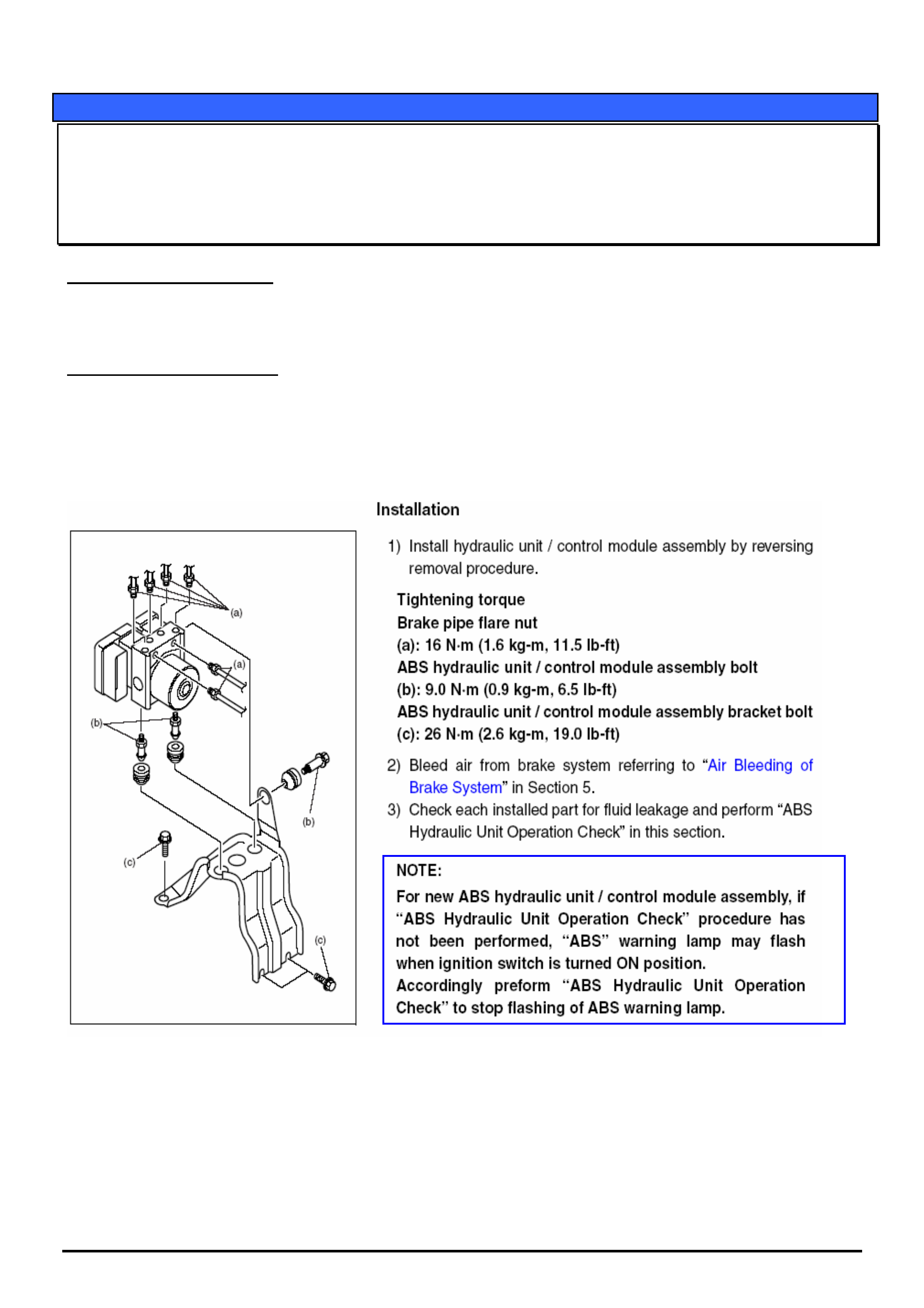
HOLDEN SERVICE TECHLINES___________________________________________________________________________DECEMBER, 2005
22
Holden Techlines are written to inform technicians of conditions that may occur on some vehicles, and to provide information that could assist in the
proper service fix of a vehicle. If a condition is described, do not assume the service fix applies to a vehicle or that the vehicle will have that condition.
SERVICE PROCEDURE
ABS Light Flashing After ABS Module Replacement
YG CRUISE
(GROUP 5) TL1028-0511
PROBLEM DESCRIPTION
The ABS Light on the cluster continues to flash after the ABS module has been replaced.
SERVICE RECTIFICATION
The above problem will occur if the correct repair & replacement procedure for ABS module as outlined in LCV SIP
is not followed. The relevant procedures from LCV SIP are copied below. Pay particular attention to the NOTE in the
box below which explains why the problem occurs.
The “A.B.S. Hydraulic Unit Operation Check (Not using Tech 2)” must be performed after module replacement;
The following procedure is a re-print from LCV SIP Section 3.3 Brakes
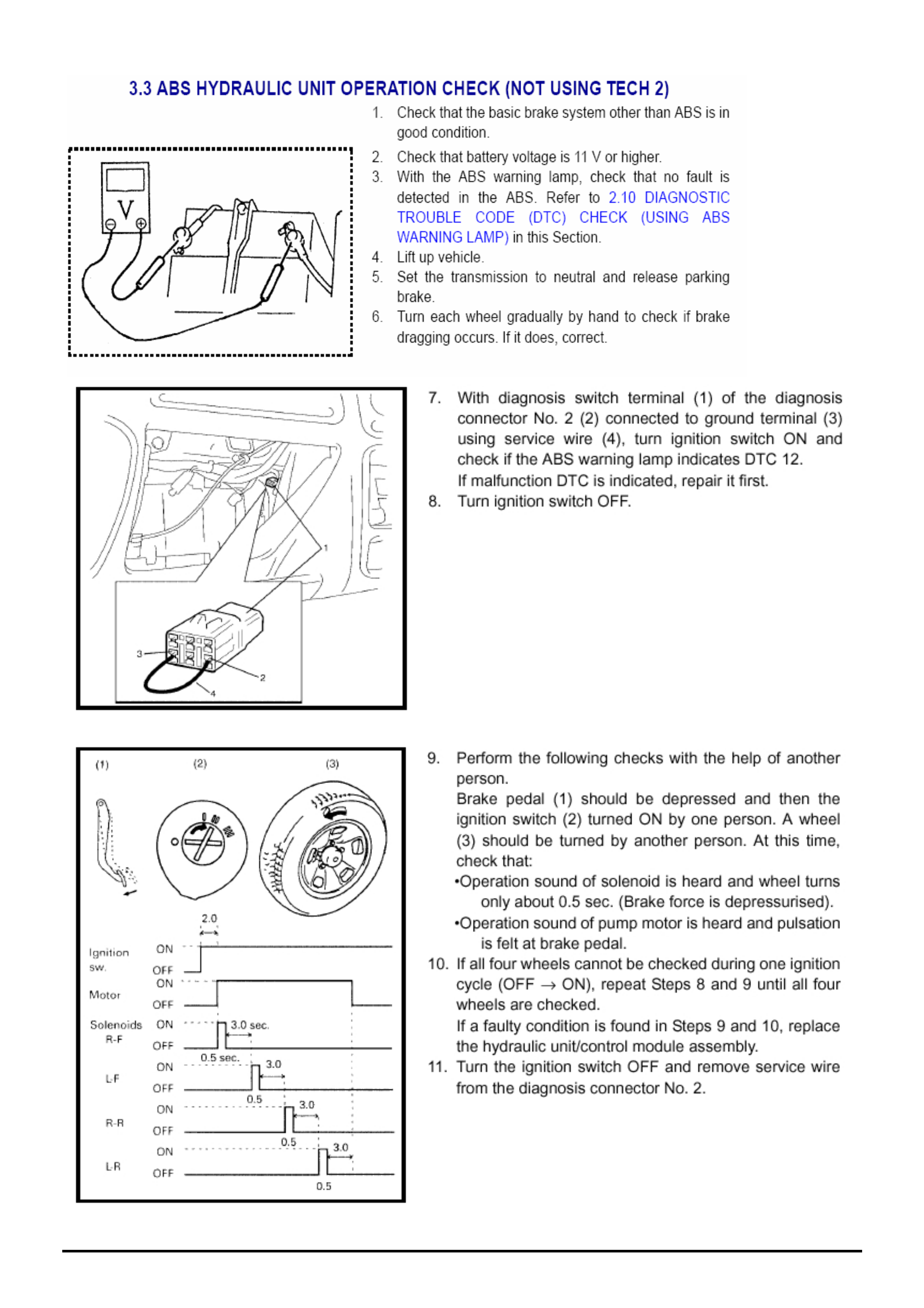
HOLDEN SERVICE TECHLINES___________________________________________________________________________DECEMBER, 2005
23
Holden Techlines are written to inform technicians of conditions that may occur on some vehicles, and to provide information that could assist in the
proper service fix of a vehicle. If a condition is described, do not assume the service fix applies to a vehicle or that the vehicle will have that condition.