
2006 SERVICE TECHLINES
© 2006 GM Holden LTD. A.B.N. 84 006 893 232
Service Department
A “Holden” Product
BRISBANE SYDNEY MELBOURNE ADELAIDE PERTH
For the latest and/or any missing Techline bulletins,
please refer to Holden Lionheart
HOLDEN SERVICE TECHLINES___________________________________________________________________________FEBRUARY, 2006
4
Holden Techlines are written to inform technicians of conditions that may occur on some vehicles, and to provide information that could assist in the
proper service fix of a vehicle. If a condition is described, do not assume the service fix applies to a vehicle or that the vehicle will have that condition.
DIAGNOSIS HINT
P1483 DTC stored in ECU
AH Astra with M/T
Group 6C & 12 Ref. No. TL1069 - 0601
CONDITION
Some Model Year 2005.5 vehicles may be presented
with an Engine Check Lamp on and DTC P1483 (Fan
Control 3 Circuit Low Voltage) stored in the engine
ECU. Vehicles with this condition may have been
incorrectly built with fuse 5 missing from the UEC
(Underhood Electrical Centre).
CORRECTION in PRODUCTION
This condition was rectified as of the following
breakpoint:
ISOVIN: Built Date:
W0L0AHL4855122854 12/01/05
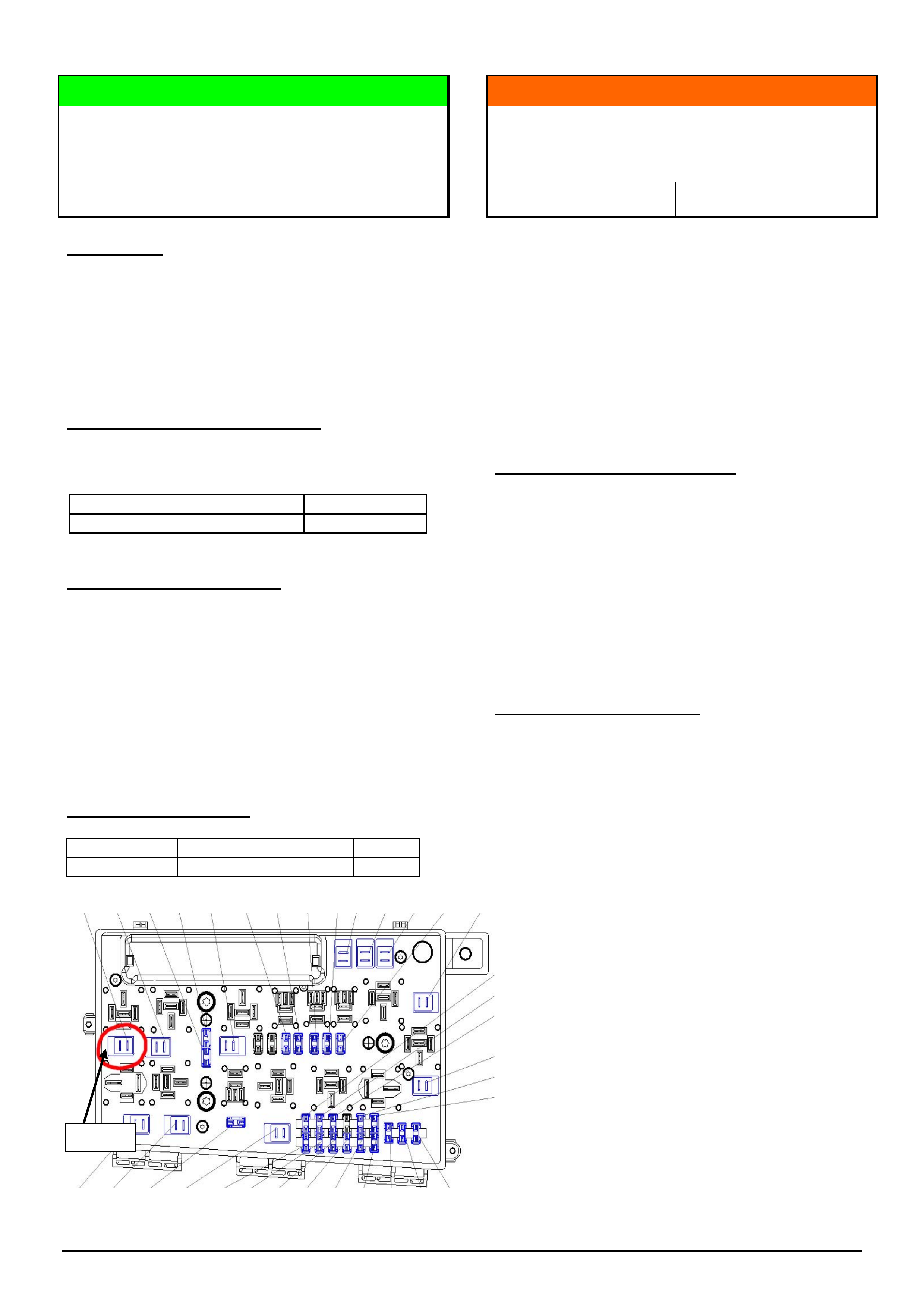
CORRECTION in SERVICE
To rectify the condition described above, install a 30A
fuse into location 5 of the UEC as shown on the
attached diagram.
Note: If fan speed 3 is commanded by Tech 2 using
the Functional Test in a vehicle with manual
transmission, it is possible that a DTC P1483 will set.
This is a normal condition and no further work will be
required.
PARTS INFORMATION
Part No.: Description: Qty:
13133860 FUSE 1
INFORMATION
Introduction of DVD for TIS 2000
All
Group OB Ref. No. TL1025A - 0601
This Techline supercedes the previous one in Issue 10,
Nov, 2005. It is revised by adding a note on setup of the
DVD drive.
From January 2006 the previous CD-ROMs for TIS
2000 will be replaced by a DVD.
The major growth in data in recent years has made
this change necessary.
Please ensure that your TIS 2000 PC has a DVD
drive by 1.1.2006 at the latest.
Advantages of changing to DVD.
• The previous data set of 4 CDs will be replaced by
one DVD
• Simpler updates, without having to change the CD
several times
• Quicker updates
• Improved quality graphics
• Use of digital photos
• Conventional CD-ROMs can also be read by DVD
drives
Important Note - DVD Setup
To guarantee a smooth update for TIS 2000, it is
essential that any new DVD drive to be used for TIS
2000 DVD’s is allocated to the letter previously used
by the CD drive. If this is not done, TIS 2000 must be
uninstalled and the DVD drive set up as a new
installation.
For more information refer to Dealer Letter 25/05 and
the TIS 2000 Newsletter available on TIS 2000 CD66.
Fuse 5

HOLDEN SERVICE TECHLINES___________________________________________________________________________FEBRUARY, 2006
5
Holden Techlines are written to inform technicians of conditions that may occur on some vehicles, and to provide information that could assist in the
proper service fix of a vehicle. If a condition is described, do not assume the service fix applies to a vehicle or that the vehicle will have that condition.
INFORMATION
Common Upper Radiator Shroud.
VZ & WL
Group 6K Ref. No. TL1006 - 0601
Service technicians should be aware that the upper
radiator shroud for V6 and V8 engine vehicles has
been made common from the Tag numbers listed
below (detailed in Microcat).
Model Tag
VZ L438762
WL L438092
Important Service Note
The removable access panel above the radiator cap
has been deleted on V8 vehicles therefore it is now
necessary to remove the upper radiator shroud to
access the radiator cap.
All replacement radiator shrouds have superseded to
the latest part (92183569). The “Cover - Radiator
Filler” (92175359) has also superseded to the latest
shroud assembly (92183569).
SERVICE FIX
“Distance To Empty” Or “Average Fuel
Consumption” Information Incorrect/Inaccurate
VZ with LPG
Group 12 Ref. No. TL1064 - 0601
CONDITION
Customer advises that the “distance to empty” or
“average fuel consumption” information displayed in
their instrument cluster is incorrect or inaccurate.
CAUSE
During programming at the VAP (vehicle assembly
plant) some instrument clusters were not configured
for LPG operation.
When configured for LPG, the “Average Fuel
Consumption” and “Distance To Empty” are removed
from the trip computer display for both LPG & Petrol
operation.
The table below gives an example of the information
displayed in the instrument cluster.
Petrol
Only
Petrol / LPG
(Dual fuel)
Digital speedometer 3 3
Stop watch 3 3
Odometer 3 3
Trip meter 3 3
Distance to go 3 3
Time to go 3 3
Distance to Empty 3 2
Average Speed 3 3
Average Fuel 3 2
Overspeed presets 3 3
CORRECTION – Service
After verifying that vehicle has the above condition,
re-configure the instrument cluster using Tech 2 via
the following steps,
1. F0: Diagnostic / Model Year / Vehicle Type / F4:
Body / Instrument / F5: Program / F1:
Configuration.
2. Scroll through the list to the engine, select the
modify soft key then select V6.
3. Scroll through the list to LPG Fitted, select the
modify soft key then select Yes.
4. Select the program soft key.
WARRANTY CLAIM INFORMATION
Use Labour Times information in Warranty Information
section of current PV SIP CD

HOLDEN SERVICE TECHLINES___________________________________________________________________________FEBRUARY, 2006
6
Holden Techlines are written to inform technicians of conditions that may occur on some vehicles, and to provide information that could assist in the
proper service fix of a vehicle. If a condition is described, do not assume the service fix applies to a vehicle or that the vehicle will have that condition.
SERVICE FIX
Turn signal / Hazard Lamps Stay Illuminated
VZ, WL
Group 12 Ref. No. TL1067 - 0601
CONDITION
Customer advises that intermittently the turn signal /
hazard lamps may stay illuminated without the switch
being activated.
CORRECTION – Production
Revised body control modules (BCM) have been fitted
to vehicles in production from the 10/08/05.
CORRECTION – Service
If a customer presents a vehicle with the above
condition, request a changeover BCM from Australian
Arrow using the standard process which is found in
SIP or on Lionheart.
WARRANTY CLAIM INFORMATION
Use Labour Times information in Warranty
Information section of current PV SIP CD
INFORMATION
Electronic Odometer Programming
TK Barina, JF Viva,
Group 12 Ref. No.TL0481A-0601
This Techline supercedes the previous one in Issue 5,
2003. It is revised by adding TK & JF models.
When a replacement instrument cluster is installed
into one of the above models it is a requirement to
program the odometer to the value of the one
removed.
If your Service Department does not know of any
instrument repairers who are capable of performing
this operation on the above models, below are some
contacts of instrument repairers currently being used
by other Dealers.
Victoria
Automotive Instrument Repairs
59 C Glenvale Crescent,
Mulgrave, Victoria 3170
Phone (03) 9561 2366
Fax (03) 9561 9134
NSW
Macarthur Instruments
P.O. Box 3016
Narellan Delivery Centre, NSW, 2567
fax (02) 4659 7294
Mobile (0416) 241 903
QLD
Future Auto Instruments
113 Turpin Rd,
Labrador, QLD 4215
Mobile (0414) 518 766
New Zealand
Robinson Instruments
19 Fale Street
Freeman's Bay
Auckland
Phone (09) 3771565
Fax (09) 3580573
HOLDEN SERVICE TECHLINES___________________________________________________________________________FEBRUARY, 2006
7
Holden Techlines are written to inform technicians of conditions that may occur on some vehicles, and to provide information that could assist in the
proper service fix of a vehicle. If a condition is described, do not assume the service fix applies to a vehicle or that the vehicle will have that condition.
SERVICE FIX
Engine RPM Flare During Upshift &
Hesitation/Flat Spot at 90 km/h
(Reprogram with Scan 100 and R-Card)
DAEWOO LACETTI with M/T
Group 6C Ref. No. TL1065 – 0601
CONDITION
Engine RPM flares or RPM “hangs-on” during gear
upshift.
Vehicle may also exhibit a hesitation or flat spot while
driving at approx. 90km/h.
NOTE: Only Manual Transmission Vehicles are
affected.
CORRECTION - Service
On complaint vehicles the ECM will need to be
reprogrammed with revised software using a Scan
100 tool and a Daewoo R-Card.
Contact your Aftersales District Manager for access to
a Scan 100 tool (if you don’t have one).
A Daewoo “Lacetti” R-card will need to be obtained
via TAS and will require a TAS case to be loaded
prior to dispatch of the R-card.
Note: this R-card contains different software to the
one for DTC 35 high idle as quoted in Service
Techline TL0978-0509 (refer Issue 9/2005) .
REPROGRAMMING PROCEDURE
Preliminary Checks.
A. Ensure battery is fully charged and all power
consuming devices are turned off.
B. Vehicle to be at full operating temperature.
IMPORTANT
The following procedure for using the “R-Card”
must be strictly adhered to.
Failure to do so may result in the irrecoverable
loss of the ECM.
Procedure
1. Ensure Scan 100 has the re-program card
inserted in the lower card slot.
Note, the main Scan 100 card is in the slot closest to
the screen of Scan100 and the re-program card is in
the lower slot. Both cards must be in the Scan 100.
2. Ensure the external 240 volt power supply is
connected to the Scan 100 unit.
3. Connect the Scan 100 to the vehicle via the data
lead and correct adaptor to the diagnostic link of the
particular vehicle. Check workshop manual for the
location of the diagnostic link connector.
4. Turn ignition on. Do not start the engine. Ignition
lights on dash illuminated.
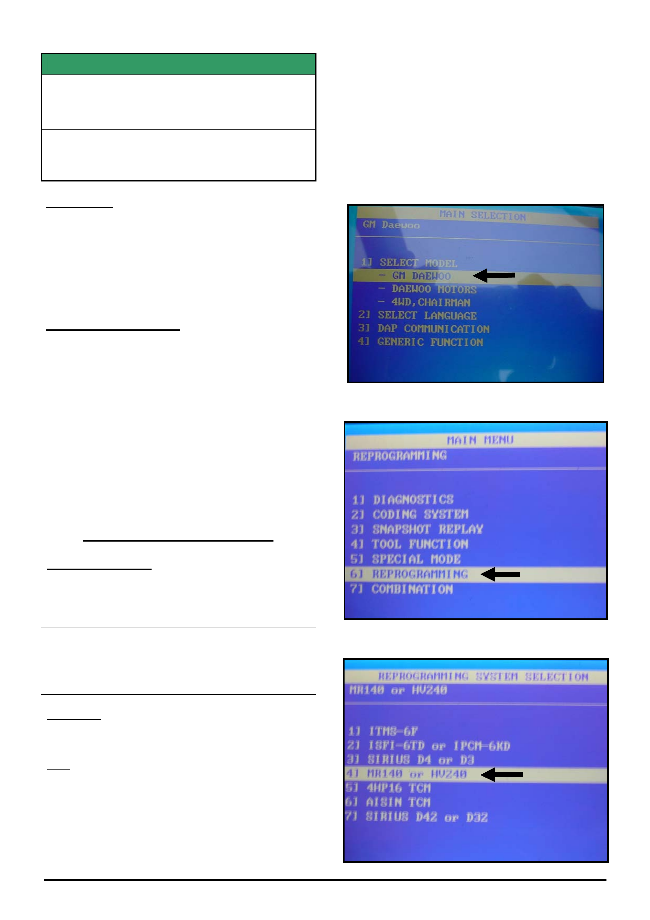
5. Turn Scan 100 tool on.
6. Select GM DAEWOO then press enter.
7/ select (6) RE-PROGRAMMING then press ENTER.
8. select (4) MR140 or HV240 then press ENTER.
HOLDEN SERVICE TECHLINES___________________________________________________________________________FEBRUARY, 2006
8
Holden Techlines are written to inform technicians of conditions that may occur on some vehicles, and to provide information that could assist in the
proper service fix of a vehicle. If a condition is described, do not assume the service fix applies to a vehicle or that the vehicle will have that condition.
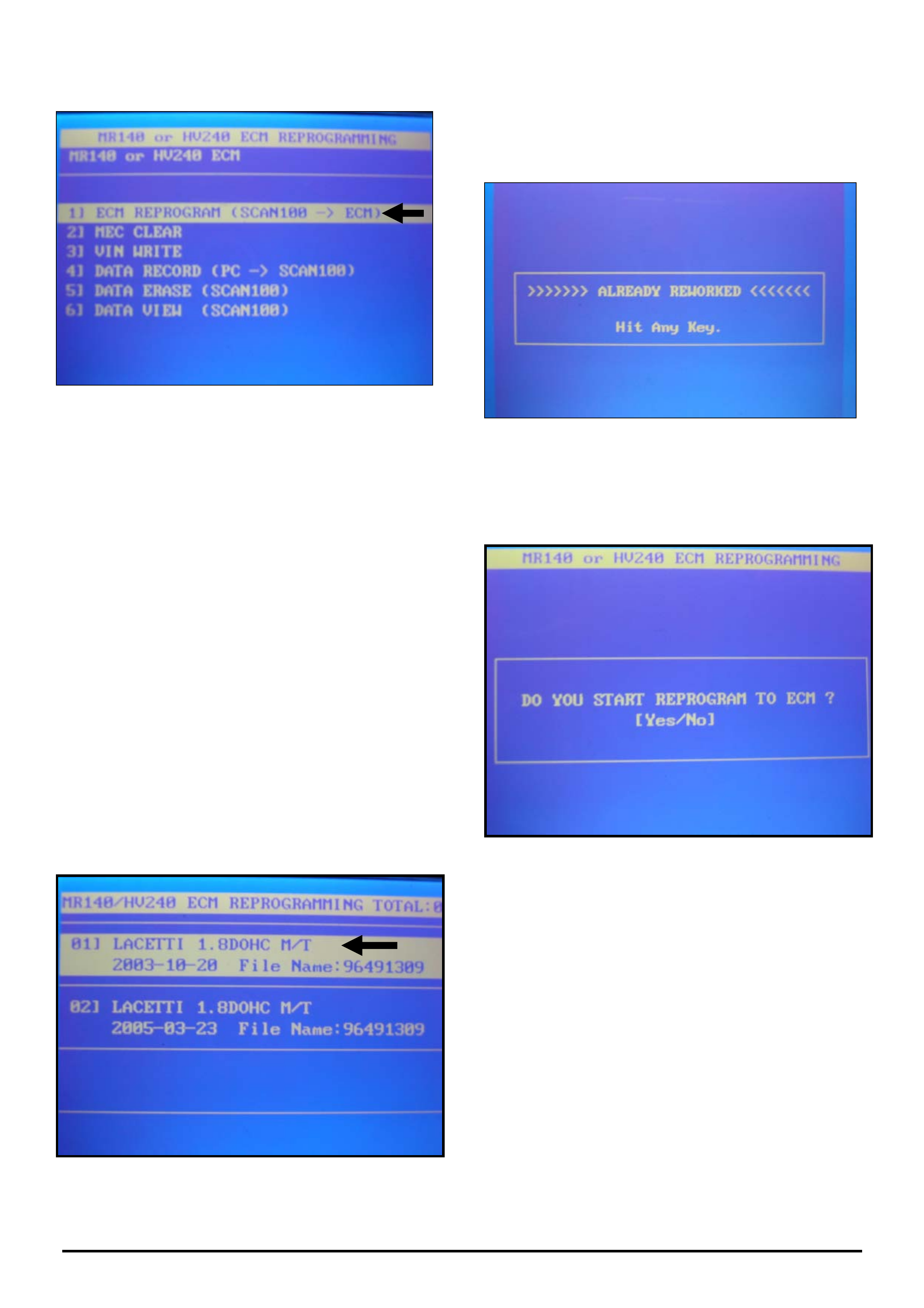
9. Select (1) ECM REPROGRAM (SCAN 100 --> ECM)
There will now be two available “files” to choose from
and they MUST be loaded in the following order.
(FIRST) LACETTI 1.8 DOHC M/T
2003-10-20 File Name: 96491309.
This file will update the ECM to avoid flat spotting /
hesitation.
(SECOND) LACETTI 1.8 DOHC M/T
2005-03-23 File Name 96491309
This file will reprogram the ECM to avoid engine
rpm “flare” between gears.
NOTE: Both files have the same file name -
”96491309”.
10. Select (01) LACETTI 1.8 DOHC M/T
2003-10-20 File Name: 96491309.
then press ENTER
Should the following message appear, then the
Calibration you are attempting, has already been
installed and you should go to step 13.
If this message does not appear then proceed to step 11.
11. A message should appear stating
“DO YOU START REPROGRAM OF ECM ?”.
Select “YES”
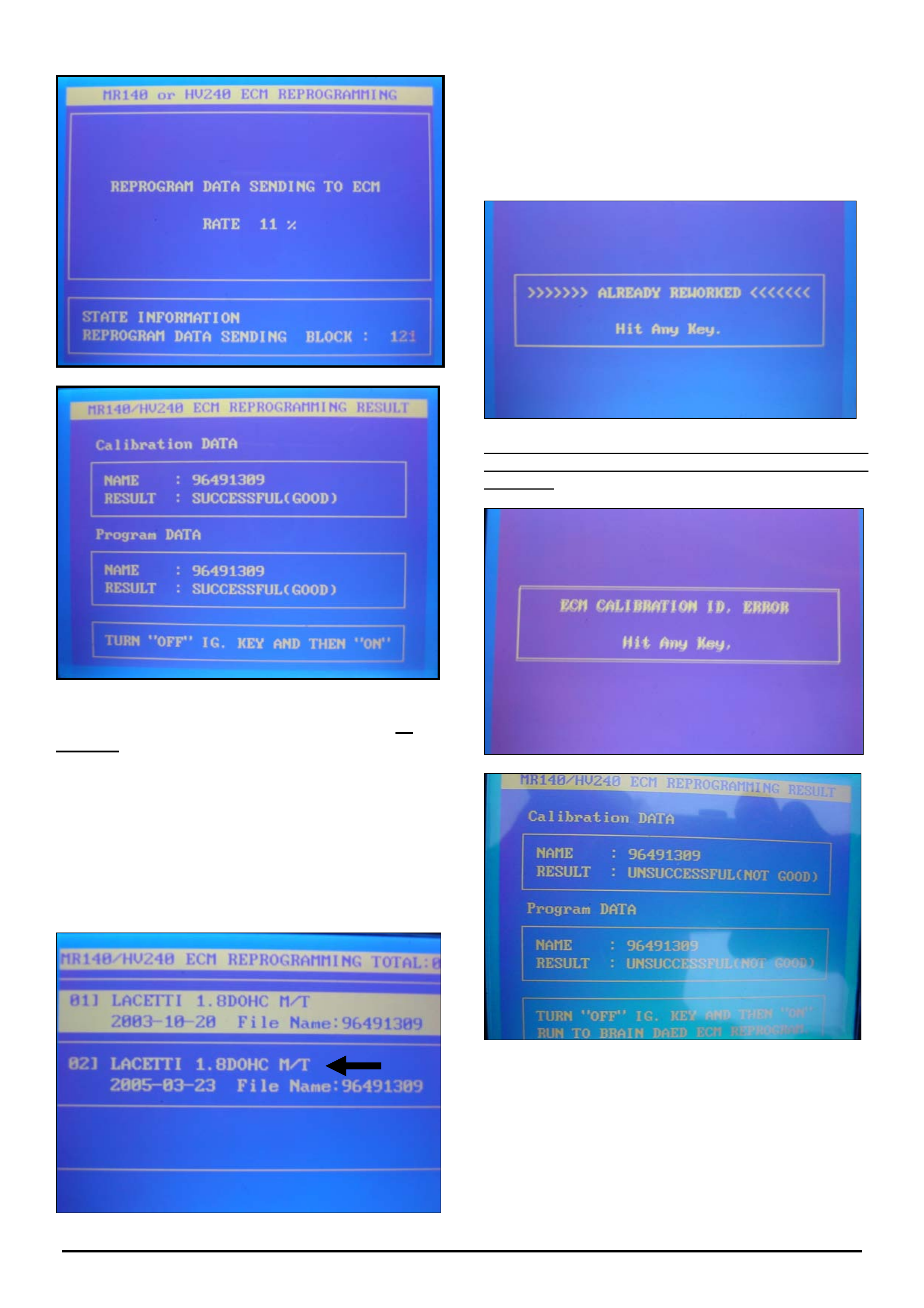
12. Wait for programming to finish.
A message stating that “REPROGRAM SUCCESSFUL
(GOOD)” will appear.
HOLDEN SERVICE TECHLINES___________________________________________________________________________FEBRUARY, 2006
9
Holden Techlines are written to inform technicians of conditions that may occur on some vehicles, and to provide information that could assist in the
proper service fix of a vehicle. If a condition is described, do not assume the service fix applies to a vehicle or that the vehicle will have that condition.
13. Turn ignition switch to the “off” position for 20
seconds. Turn ignition switch to “on” then start
engine.
14. Press “esc”. several times to return to the main
screen.
15. Repeat Steps 6 to 9.
16. Select (02) Lacetti 1.8 DOHC M/T
2005-03-23 File Name 96491309.
Press ENTER and repeat steps 11 to 14 as above.
Should the following message appear, then the
Calibration you are attempting, has already been
installed and no further action is required.
Should either of the 2 messages below appear, contact
TAS prior to disconnecting or exiting procedure with
Scan 100.
HOLDEN SERVICE TECHLINES___________________________________________________________________________FEBRUARY, 2006
10
Holden Techlines are written to inform technicians of conditions that may occur on some vehicles, and to provide information that could assist in the
proper service fix of a vehicle. If a condition is described, do not assume the service fix applies to a vehicle or that the vehicle will have that condition.
SERVICE FIX
Glove Compartment Door Opens Too Far
VY, VZ, V2 II & III, WK, WL
Group 1 Ref. No. TL0854A-0601
This Techline supercedes the previous one (TL0854-0502)
in Issue 2, Mar, 2005. It is revised as both previous bump
stops have been superseded by a new part number.
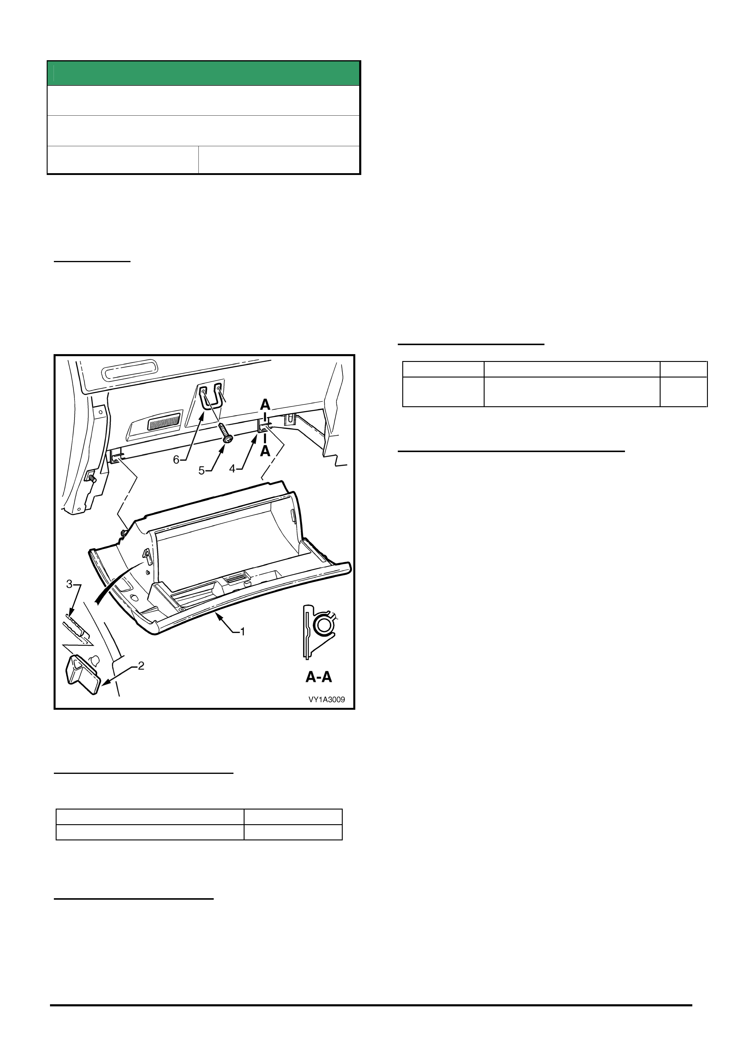
CONDITION
Glove compartment door rubber bump stops may
tear in service. As a consequence, the glove
compartment swings fully downward when opened
and is not restrained by the stops.
The bump stop is shown as key #2 in figure below.
Figure 1.
CORRECTION – Production
Revised bumpstops have been fitted to vehicles from:
ISOVIN: Built Date:
0000000000L486687 3rd AUG 2005
CORRECTION – Service
1. Inspect the bump stops on both sides of the glove
compartment, to confirm whether one or both stops
are torn.
2. Remove the glove compartment using the
procedure outlined in Holden SIP Section 1A3 para
3.2, taking care to avoid damaging the glove
compartment while removing hinge pins.
3. Remove damaged bump stop/s.
4. Fit new bump stops 92186491.
5. Reinstall glove compartment as follows:
Engage lower hinge points, then rotate glove
compartment up into closed position whilst pushing
sideways to compress one of the bump stops. This
action is required to provide clearance for the other
bump stop as it slides over the Instrument Panel
structure.
PARTS INFORMATION
Part No.: Partfinder Name Qty:
92186491 Bumper instrument panel
compartment door
1
WARRANTY CLAIM INFORMATION
Use Labour Times information in Warranty
Information section of current PV SIP CD
HOLDEN SERVICE TECHLINES___________________________________________________________________________FEBRUARY, 2006
11
Holden Techlines are written to inform technicians of conditions that may occur on some vehicles, and to provide information that could assist in the
proper service fix of a vehicle. If a condition is described, do not assume the service fix applies to a vehicle or that the vehicle will have that condition.
DIAGNOSIS HINT
CAN-bus Configuration Mismatch DTC’s
AH Astra, ZC Vectra
Group 12 Ref. No. TL1050 - 0601
CONDITION
Trouble codes (DTC’s) may be stored after replacing
modules that communicate on the CAN-bus network.
These DTC’s may be stored in multiple modules if the
configurations are different.
The configurations in these modules must all be
programmed the same, otherwise the following DTC will
set.
“CAN-bus Configuration Mismatch”
This highlights the importance of ALWAYS starting
diagnosis with a “Module / ECU Presence Check” as
shown in the following screen from Tech2.
Figure 1
This “Presence Check” not only checks the modules are
present and communicating on the CAN-bus, but also
checks that ALL the modules are configured the same.
If a mismatch is detected, Tech 2 will display the
module(s) concerned then automatically prompt you
through the configuration process.
This procedure saves time by not having to check and
reprogram each module individually.
INFORMATION
Camshaft identification
SB Barina,
TR / TS / AH Astra,
JR / JS / ZC Vectra
Group 6A Ref. No. TL1063-0601
When performing cylinder head repairs on the twin
cam engines fitted to the above models (see list of
engines below) some technicians have had difficulty
with identification of camshafts.
C18SEL, C16XE, C20SE, C22SE
X16XE, X18XE1, X20XEV, X25XE, Z18XE
Z20LET, Z22SE
Y26SE
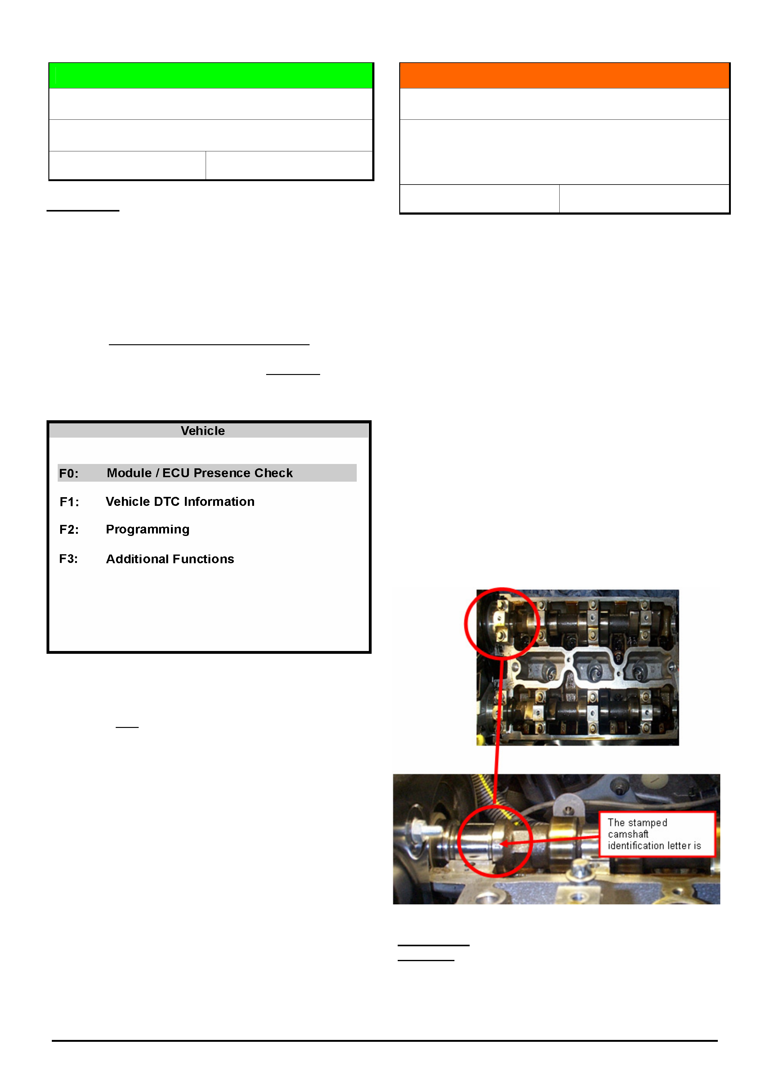
Most camshafts can be identified by the following
markings which are located near the first cam bearing
or cam drive gear end.
The letter "H" or "C" or "Z" = inlet
The letter " I “ or "T" or "Y" = exhaust
Z32SE Engine has the following identification:
G = Inlet Camshaft
J = Exhaust camshaft
Location of Z32SE markings is as follows:
↑
Gear end of
camshaft
HOLDEN SERVICE TECHLINES___________________________________________________________________________FEBRUARY, 2006
12
Holden Techlines are written to inform technicians of conditions that may occur on some vehicles, and to provide information that could assist in the
proper service fix of a vehicle. If a condition is described, do not assume the service fix applies to a vehicle or that the vehicle will have that condition.
SERVICE FIX
SRS light Illuminates
JF Viva
Group 12 Ref. No. TL1045 - 0601
CONDITION
SRS light may be illuminated in the instrument cluster
with various SRS circuit DTC’s set in the SDM.
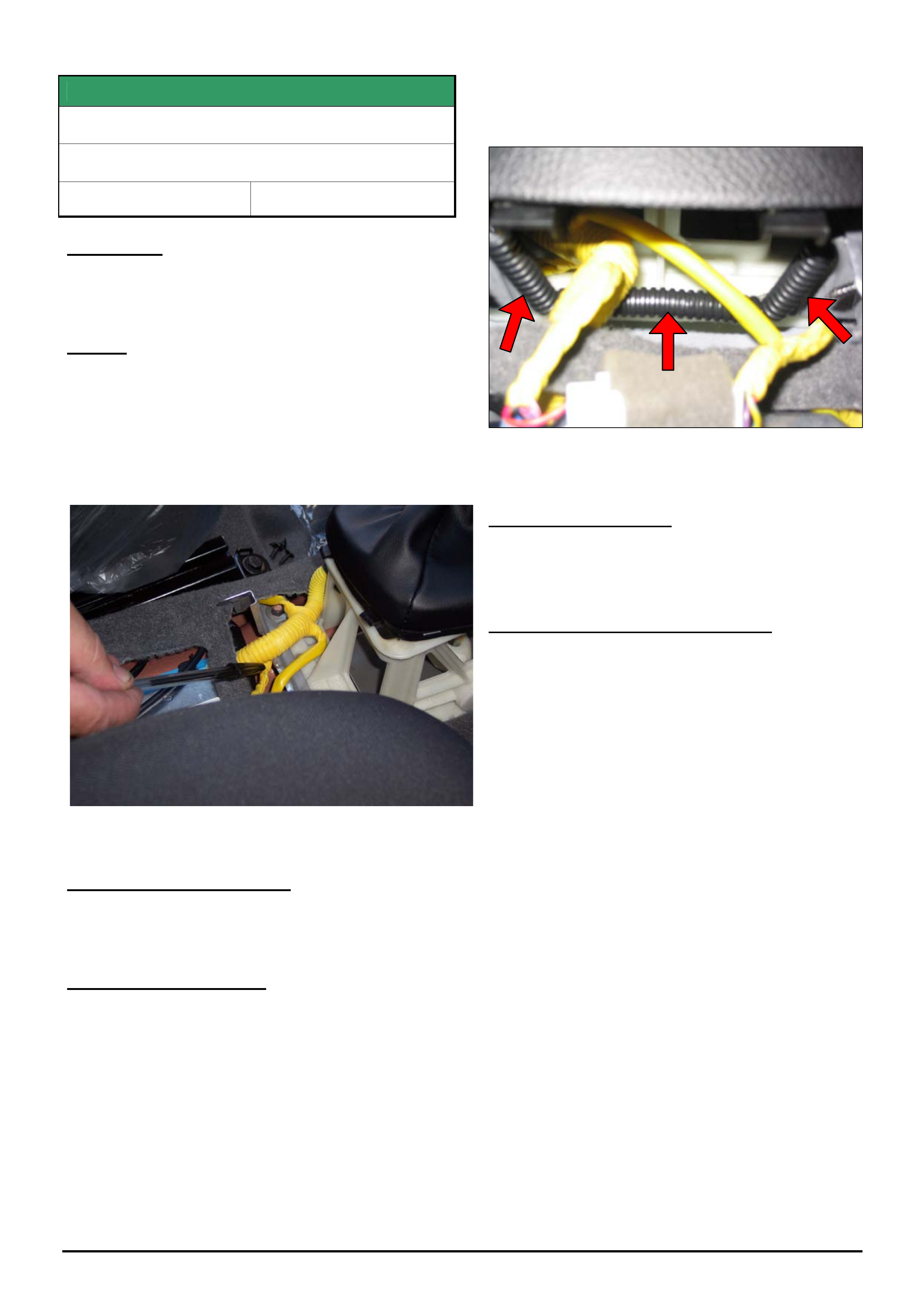
CAUSE
The SRS wiring harness under the centre console
between the SDM and the transmission shifter may
have been damaged by a sharp metal edge, causing a
short to ground and various DTC’s to set.
Damage may occur to any of the circuits contained
within this harness resulting in a variety of different
DTC’s.
Figure 1 Shows location of damage
CORRECTION – Production
Vehicle’s shipped from POE (Port Of Entry) after the
14/11/05 have been inspected for this condition.
CORRECTION – Service
If presented with a vehicle shipped from POE prior to
14/11/05 with the SRS light on, perform the following
steps:
1. Carefully inspect the SRS harness in the
location described above.
2. If wiring damage is discovered, repair and re-
insulate.
3. Ensure the sharp edge on the metal bracket
shown below is covered with a piece of
convoluted tube to prevent further damage.
Figure 2. Shows convoluted tubing placed over sharp
edge.
PARTS INFORMATION
Use any commercially available convoluted tubing of
approx. 9mm diameter.
WARRANTY CLAIM INFORMATION
Use Labour Times information in Warranty Information
section of current PV SIP CD for wiring repairs.
HOLDEN SERVICE TECHLINES___________________________________________________________________________FEBRUARY, 2006
14
Holden Techlines are written to inform technicians of conditions that may occur on some vehicles, and to provide information that could assist in the
proper service fix of a vehicle. If a condition is described, do not assume the service fix applies to a vehicle or that the vehicle will have that condition.
SERVICE PROCEDURE
Driveline Clunk/Backlash from Rear Axle
VZ (with IRS or Beam Axle)
Group 4 Ref. No. TL0853 - 0601
This Techline provides a Lash Check procedure for IRS
Rear Axle Assemblies and supersedes the previous bulletin
(TL0815-0410) on VY/VZ Differential Clunk Noise in Issue
10, Nov. 2004.
IMPORTANT BACKGROUND INFORMATION
Before commencing the procedures provided in this
Techline and to ensure that unnecessary
measurements or repairs are not conducted,
Technicians and Service Advisors must be aware of
and have read the following Service Techlines:
- Explanation of Driveline Clunk or backlash Noise –
refer July 2005 (Issue 6, page 16).
- Suspected Clunk from Driveline - refer October
2005 (Issue 9, page 10 – spare wheel related).
Service Advisors in particular need to ensure that they
clearly understand the reported condition so that the
condition can be reproduced by the dealership
technician and so that customers can be immediately
advised of those conditions that are normal drivetrain
related operating noises.
DO NOT proceed any further if the clunk noise is
confirmed as a normal or characteristic driveline
system operating noise.
Various components in the driveline system can
produce noise as a result of the application and
release of torque through the driveline. This Techline
provides the procedures to be followed to determine
whether the cause of abnormal “Clunk” noise is
caused by excessive clearance within the differential
unit.
The procedures below provide a structured and
accurate method of measuring combined differential
assembly backlash in both Beam axle assemblies and
IRS final drive units when the noise is classified as
abnormal or excessive when compared to other
equivalent specification vehicles. This measurement
procedure will also ensure that components are not
replaced unnecessarily
A. Evaluation of Concern
- Road test the vehicle to repeat the customer
reported concern
- Use the Driveline Noise Definition Worksheet
attached to record details of the complaint condition.
- This worksheet will also record the necessary
information for the Dana Website Request Form
should a replacement diff be required.
- It is essential that the driving conditions, when the
reported concern occurs, is recorded.
- It is also important that the condition is compared
to an equivalent specification vehicle to assist
determining whether the concern is a normal or
characteristic noise or is abnormal.
- If an equivalent vehicle is not available to
compare against and you are unsure whether the
noise level is normal or abnormal, then proceed to
Step B. Otherwise, no further action is required.
B. Vehicle set up for measurement
- Prepare vehicle for measurement by accelerating
forward and then reverse with moderate throttle.
- Drive vehicle onto a four post hoist.
- Apply handbrake firmly
- Raise vehicle
C. Differential Lash Check
For Beam Axle Assemblies
Perform a rear axle backlash check using the
procedure described in PV SIP found as follows:
Section 4B2 – Rear Final Drive and Live Axle
2 – Minor Service Operations
2.6 – Combined Rear Axle Backlash Check
Should the measured backlash be greater than 3.0mm
– the measured backlash dimension MUST be
included in the Dana request application.
The combined backlash specification for the Beam
Rear Axle Assembly is 3.0 mm
DO NOT request a replacement axle if backlash is less
than 3.0mm.
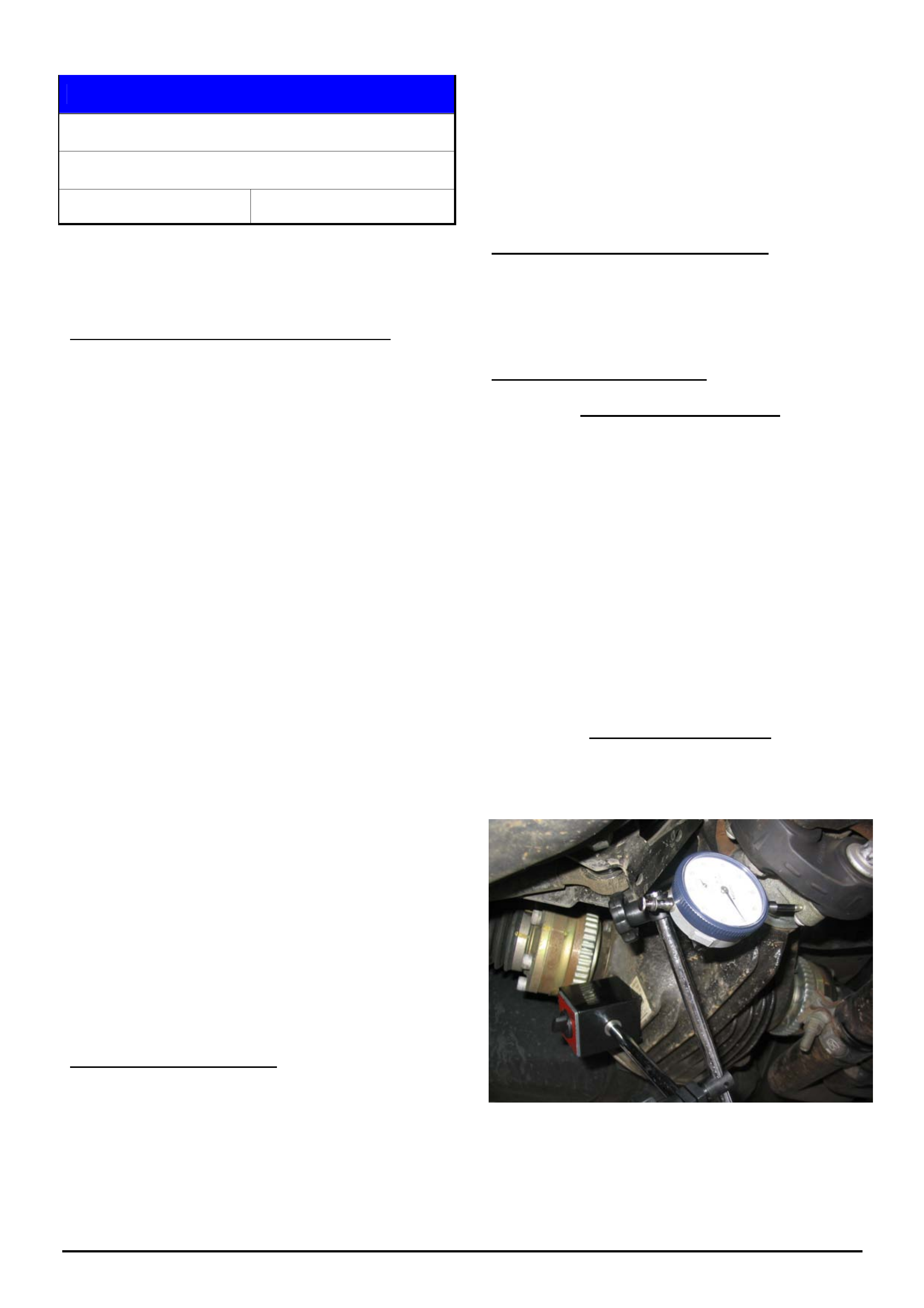
For IRS Final Drive Units
1. Attach magnetic dial indicator base to the diff
housing and probe the pinion flange as shown in
Photo 1 below.
Photo 1: Diff pinion flange measurement.
2. Have an assistant TWIST both inner driveshaft
CV’s in the same direction against the applied
handbrake and HOLD in this position.

HOLDEN SERVICE TECHLINES___________________________________________________________________________FEBRUARY, 2006
15
Holden Techlines are written to inform technicians of conditions that may occur on some vehicles, and to provide information that could assist in the
proper service fix of a vehicle. If a condition is described, do not assume the service fix applies to a vehicle or that the vehicle will have that condition.
3. Rotate the propshaft with hand torque in one
direction and set the dial indicator to zero.
4. Rotate the propshaft with hand torque in the
opposite direction and take a reading of the travel.
5. Provided a rotational movement is applied to the
propshaft and even torque is applied in both
directions, then the measurement taken
represents the lash within the differential unit.
6. Repeat the measurement procedure above with
both the inner driveshaft CV’s twisted in the
opposite direction to step 5 above, to confirm an
accurate and repeatable lash measurement.
7. The combined backlash specification for the IRS
Differential unit is 3.0 mm.
8. Record both measurements taken and the
specification value on the Repair Order.
D. Service Correction
When the lash check shows that the differential lash
reading is within specification then the differential unit
is not the cause of the abnormal clunk noise condition.
When the lash check shows a lash measurement of
greater than 3.0 mm then request a replacement
beam axle or IRS Diff unit from Dana – refer to your
Zone Aftersales representative in case approval is
required.
HOLDEN SERVICE TECHLINES___________________________________________________________________________FEBRUARY, 2006
16
Holden Techlines are written to inform technicians of conditions that may occur on some vehicles, and to provide information that could assist in the
proper service fix of a vehicle. If a condition is described, do not assume the service fix applies to a vehicle or that the vehicle will have that condition.
Attachment to Service Techline TL0853-0601
Driveline Noise Definition Worksheet Date: _____________________
Dealership: _____________________________________ Dealer Code: _____________________
Completed by: __________________________________ Return Fax No.: ______________________
ISOVIN No.: ___________________________________________
Axle Serial No. _______________________
Axle Part No.: _______________________
Vehicle Type: VY VZ
Crewman (Beam) 1-Tonner (Beam) Sedan/Wagon/Ute (IRS)
Engine: V6 V8
* Confirm the customer complaint via road test THEN describe it using the chart below:
Circle comments as required.
Noise Description (Circle)
CLUNK WHINE SQUEAK GRIND
For CLUNK – Backlash Measured is: _______ mm
Affected Speed Range:
10 20 30 40 50 60 70 80 90 100 110
Gear: Automatic
(Circle Lever Position):
D 4 3 2 N R
Gear: Manual
(Circle Gear Selected):
1 2 3 4 5 6 R
Accelerator Applied:
OR When at Coast:
Light Medium Heavy Cruise
Yes No
Dealer Action: Order new axle from Dana
Have axle rebuilt * Supply Sub-Let Report with PIR
Nothing
Other: Define: ___________________________
Zone Authorisation Number: ______________________________ (For use on Dana Website Request)
Additional Comments:
Dana WERN No. (if supplied): ____________________________
HOLDEN SERVICE TECHLINES______________________________________________________________________________MARCH, 2006
5
Holden Techlines are written to inform technicians of conditions that may occur on some vehicles, and to provide information that could assist in the
proper service fix of a vehicle. If a condition is described, do not assume the service fix applies to a vehicle or that the vehicle will have that condition.
DIAGNOSIS HINT
A/C Compressor not working
AH Astra & ZC Vectra fitted with ECC
(Electronic Climate Control)
Group 2 Ref. No. TL1077-0602
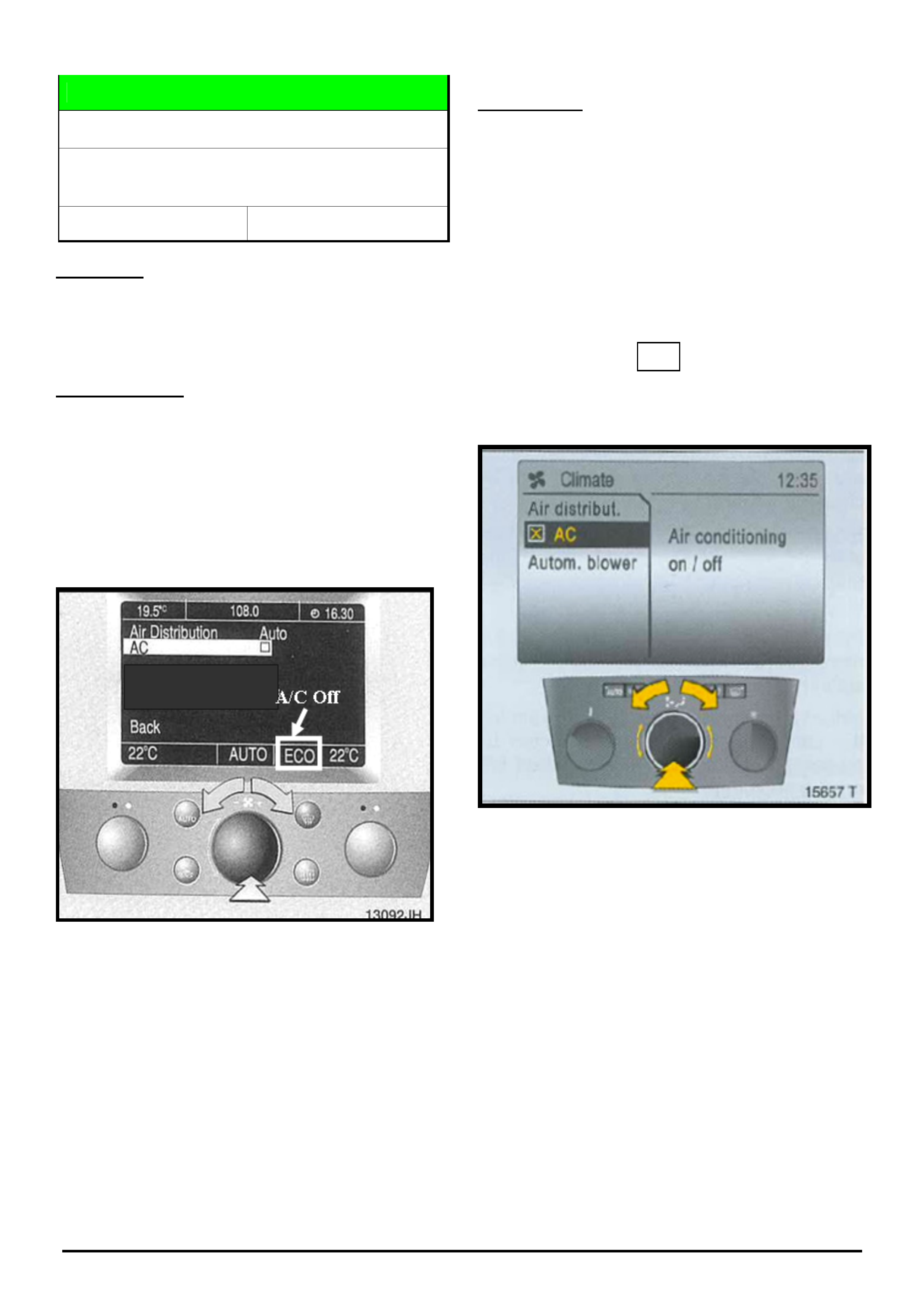
CONDITION
Air conditioning is not cold, or A/C compressor does not
operate on vehicles fitted with ECC after vehicle
delivery.
DIAGNOSIS HINT
As a result of ECC settings being unintentionally
changed by the user, the A/C compressor can be
permanently turned off via the A/C selection menu in the
information display.
When the A/C compressor is set to off, “ECO”
(Economy) is displayed as shown in the following screen
which is from an early type ZC Vectra.
(ZC Vectra, early type – shows A/C off).
CORRECTION
Customers should be educated on how to set the ECC
so that the compressor is set to “on”.
The procedure for doing this is as follows.
Press the main ECC control button to enter the A/C
Menu screen. From the options which are displayed,
ensure the A/C compressor is switched on by placing
the “X” in the box. Refer picture below.
1. Air Distribut.
2. A/C
3. Autom. blower
(AH Astra-shows A/C on)
Note. Warranty claims must not be submitted for this
condition as this is an ECC setting issue only.
X
A/C
Menu
A/C
Menu
HOLDEN SERVICE TECHLINES______________________________________________________________________________MARCH, 2006
6
Holden Techlines are written to inform technicians of conditions that may occur on some vehicles, and to provide information that could assist in the
proper service fix of a vehicle. If a condition is described, do not assume the service fix applies to a vehicle or that the vehicle will have that condition.
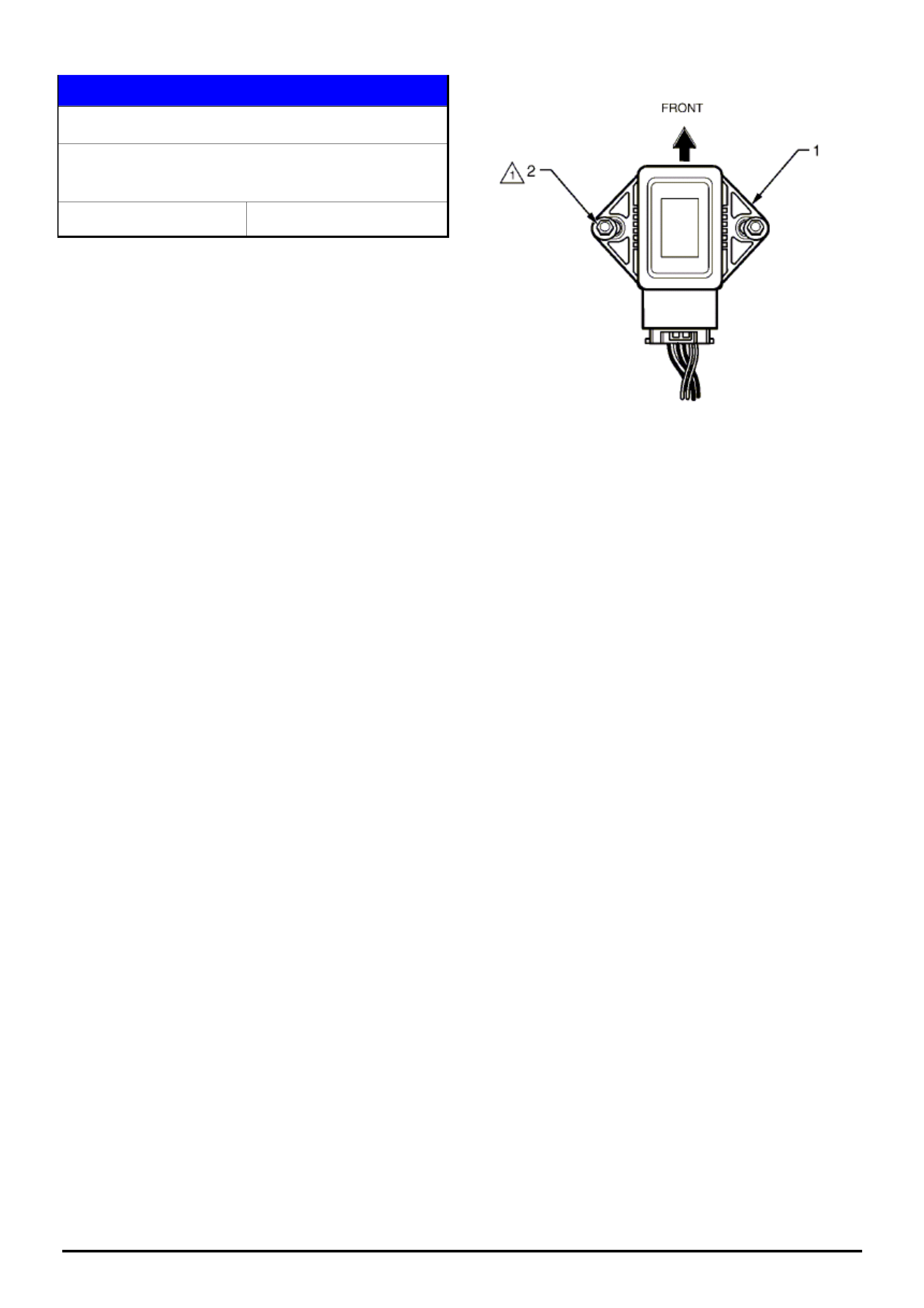
SERVICE PROCEDURE
Yaw Rate Sensor Orientation
VZ, WL, with ESP (Electronic Stability
Program)
Group 12 Ref. No. TL1078-0602
This techline is written to inform technicians of the
correct orientation of the Yaw Rate sensor as fitted to
the above models as it has been proven possible to
reinstall it in the opposite direction.
Please refer to the attached diagram which is taken
from Passenger Vehicle SIP.
It is important to note the orientation in relation to the
front of the vehicle and also the electrical connector
into the sensor. The attaching nut torque is 7-11 Nm.
HOLDEN SERVICE TECHLINES______________________________________________________________________________MARCH, 2006
7
Holden Techlines are written to inform technicians of conditions that may occur on some vehicles, and to provide information that could assist in the
proper service fix of a vehicle. If a condition is described, do not assume the service fix applies to a vehicle or that the vehicle will have that condition.
DIAGNOSIS HINT
A/T Malfunction or Shift Problems, Various
DTC’s set.
V & W models with 4L60E or 4L65E A/T
Group 7B Ref. No. TL1076 - 0602
CONDITION
Customer may report various symptoms that suggest
incorrect shifts, changes or deterioration in the
transmission functions, and the Powertrain lamp may
be “on”.
Tech 2 may show various DTC’s are set.
DIAGNOSIS HINT
First - Define if the transmission is definitely NOT
functioning correctly – Refer to Information Techline
(TL0887-0504) in May, 2005, Issue 4, page 13.
If the transmission features information detailed in this
techline does not explain the customer’s concern, then
proceed as follows:
A possible cause for the above symptoms is a “poor”
harness connection to the transmission. Therefore it is
essential when performing any A/T related diagnostics,
to include checking the harness connection to the
transmission as follows.
1. Unplug the connection at the transmission.
2. Visually inspect for any damaged terminals. (bent
or burnt)
3. Replace harness if burnt, and/or attempt to
restraighten any bent terminals using fine nose
pliers.
4. Reconnect harness plug firmly.
5. Road test vehicle for original complaint.
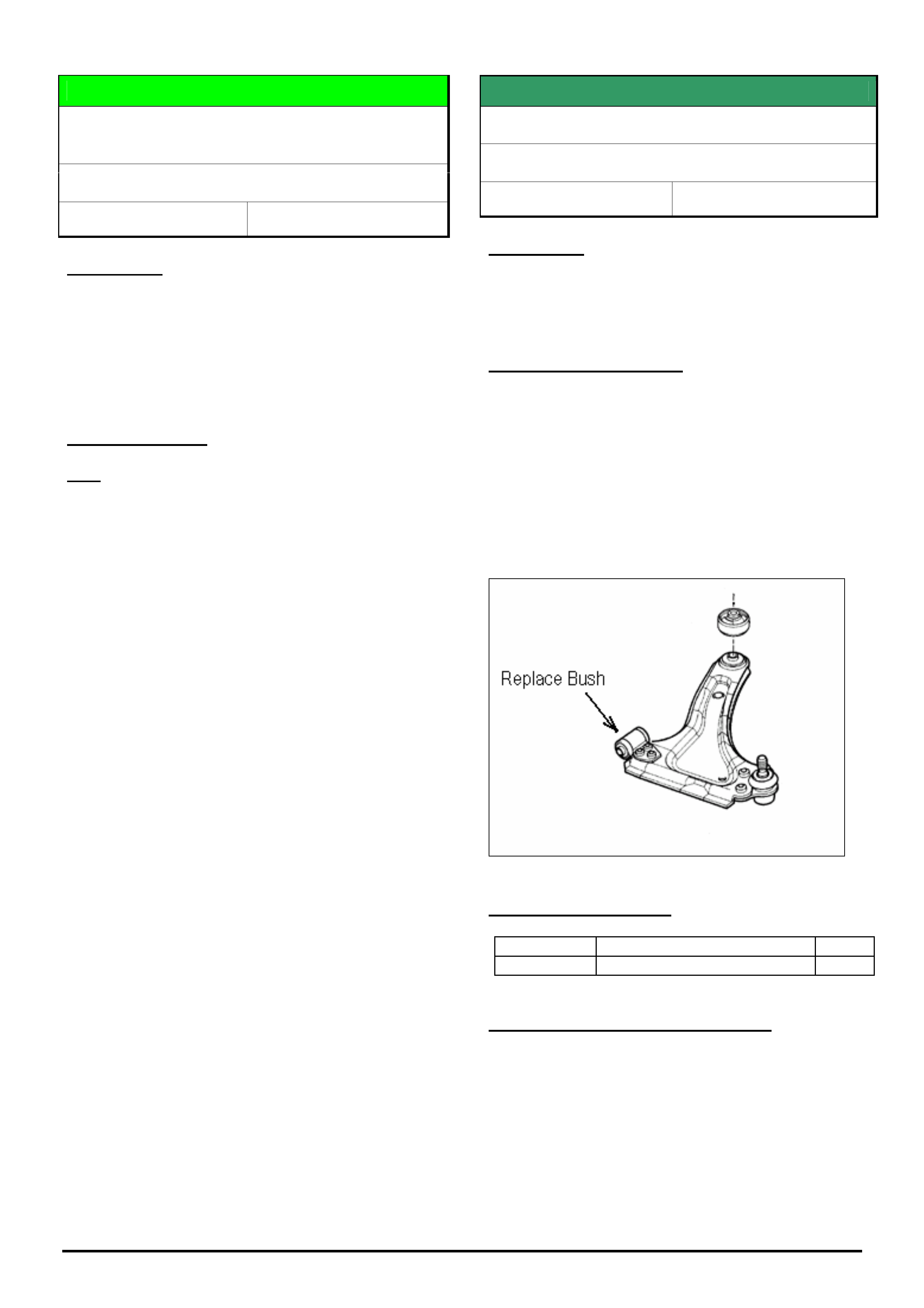
SERVICE FIX
Front Lower Control Arm Bush Squeak
XC Barina
Group 3 Ref. No. TL0994 - 0602
CONDITION
On some vehicles a creak noise may be heard coming
from the front suspension control arm bush when
travelling over speed bumps.
CORRECTION – Service
After verifying vehicle has the condition as described
above, fit revised bushes (part number 93188303) to
the front lower control arms.
These revised bushes have been developed to
overcome the creak condition.
Revised bushes should be fitted to both front lower
control arms as per procedure in TIS.
PARTS INFORMATION
Part No.: Description Qty:
93188303 Lower control arm bush 2
WARRANTY CLAIM INFORMATION
Use Labour Times information in Warranty Information
section of current PV SIP CD
HOLDEN SERVICE TECHLINES______________________________________________________________________________MARCH, 2006
8
Holden Techlines are written to inform technicians of conditions that may occur on some vehicles, and to provide information that could assist in the
proper service fix of a vehicle. If a condition is described, do not assume the service fix applies to a vehicle or that the vehicle will have that condition.
DIAGNOSIS HINT
Rear Park Assist (RPA) Behaves Erratically
With Trailer Attached
VY,VZ (wagon, sedan, coupe) WK,WL,V2 with
Factory Fitted RPA
Group 12 Ref. No. TL0991 - 0602
CONDITION
Customer complains that their vehicle’s Rear Park
Assist (RPA) system behaves erratically when they
hook up a trailer.
CAUSE
The above condition may be caused by fitment of the
wrong trailer harness, or an incorrectly fitted harness.
Notes:
The correct harness for use on VZ and WL models
fitted with RPA is part number 92144494. (Flat 7 pin ).
There are two other harnesses available for the above
models which are for vehicles without RPA (option
code UD7). Ensure that neither of these harnesses is
fitted.
The correct harness 92144494 must be installed as
per the procedure shown in the fitting instructions. A
copy of these instructions (p/n FD1095) may be found
in Passenger Vehicle SIP under “Accessories Fitting
Instructions”.
If your trailer has a round plug, you must use one of
the adapter harnesses as specified in Microcat.
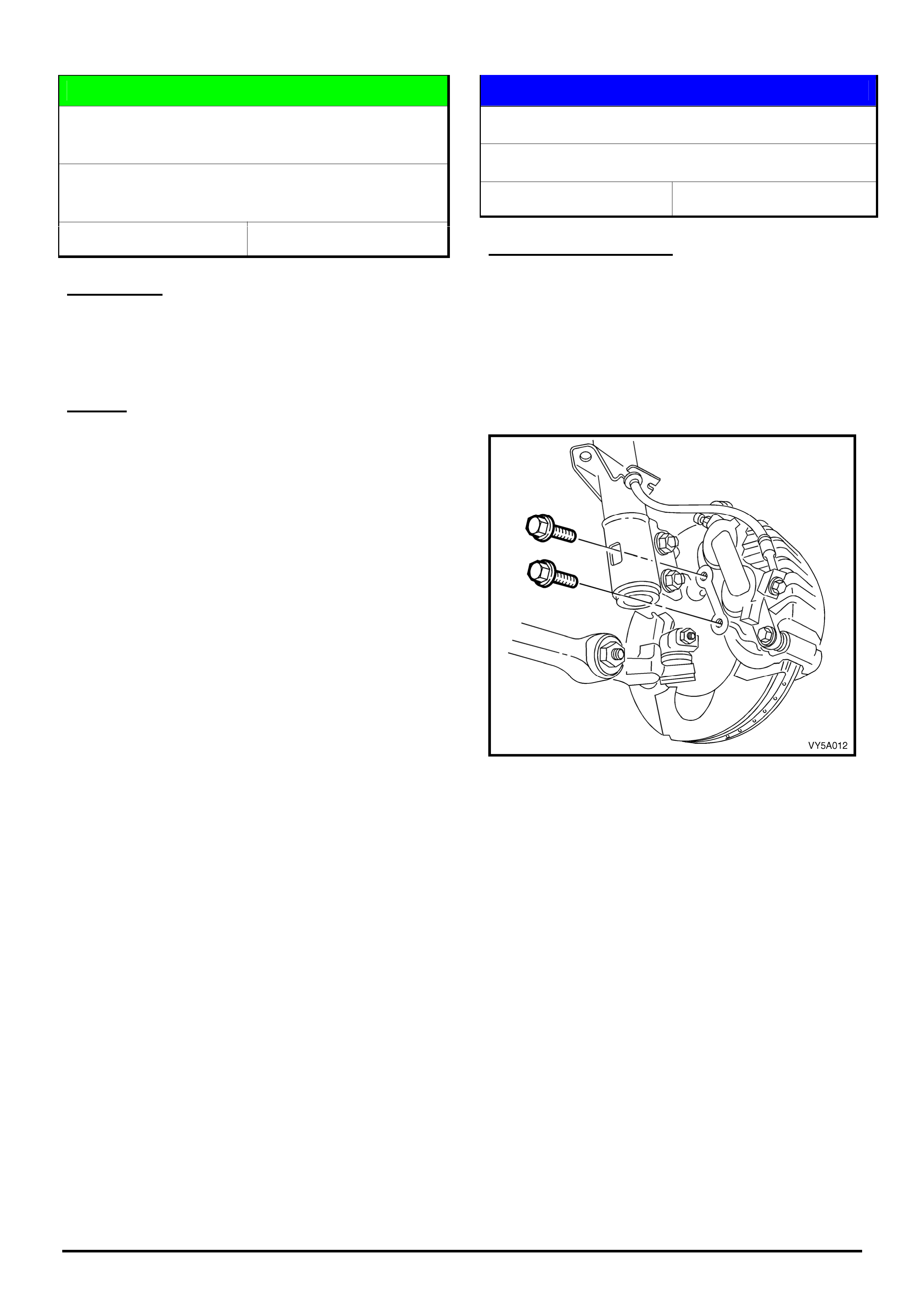
SERVICE PROCEDURE
Front Brake Caliper Anchor Bolts
VT, VU, VX, V2, VY, VZ, WH, WK, WL
Group 5 Ref. No. TL1070 - 0602
IMPORTANT REMINDER
The front caliper anchor bolts are a “single use” only
bolt which means they must be replaced after removal.
(Also refer to PV SIP)
Also, these bolts must be tightened using the torque
turn method. (refer SIP for torque specification)
Front caliper attaching bolts.
HOLDEN SERVICE TECHLINES______________________________________________________________________________MARCH, 2006
9
Holden Techlines are written to inform technicians of conditions that may occur on some vehicles, and to provide information that could assist in the
proper service fix of a vehicle. If a condition is described, do not assume the service fix applies to a vehicle or that the vehicle will have that condition.
SERVICE FIX
Diff. Period Whine, 80 – 110 km/h
VY & VZ – One Tonner & Crewman
Group 4 Ref. No. TL0631C-0602
This Techline supersedes the previous one in Issue 11, Dec.,
2005. It is UPDATED by adding V6 M/T to the models which
can now be fitted with the revised pinion flange (2-spoke).
CONDITION
Some vehicles may experience an unacceptable
period whine noise from the differential at
approximately 80 - 110 km/h at light to medium throttle
cruising.
A certain level of rear axle assembly noise is normal
and to be expected on these light commercial type
vehicles due to their cab chassis structure and
associated load carrying requirements.
NOTE: This noise must not be confused with noises
resulting from possible faulty differential bearings or
gears.
CORRECTION – Production
Two countermeasures have been introduced into
production on the specific models as listed:
• A softer rubber bush in the front eye of the leaf
spring. – Crewman V8 (A/T & M/T), (RWD & AWD)
• A 2-spoke pinion flange – Crewman V8 A/T (RWD
only)
Breakpoint for both countermeasures in Crewman is:
ISOVIN: Built Date:
**********L218227 09/03/2004
CORRECTION – Service
Summary: After verifying that complaint vehicle has
condition as described above, fit revised bushes in
front eye of rear springs of ALL vehicles. Also, for V8
& V6( M/T) Rear Wheel Drive ONLY - fit a 2-spoke diff
pinion flange.
Procedure. (For specific procedures not covered in detail
refer to latest PV SIP.)
1. Remove rear springs.
2. Press out existing front eye bush from each spring.
3. Press in new eye bush p/n 92148815.
4. Reinstall spring assemblies.
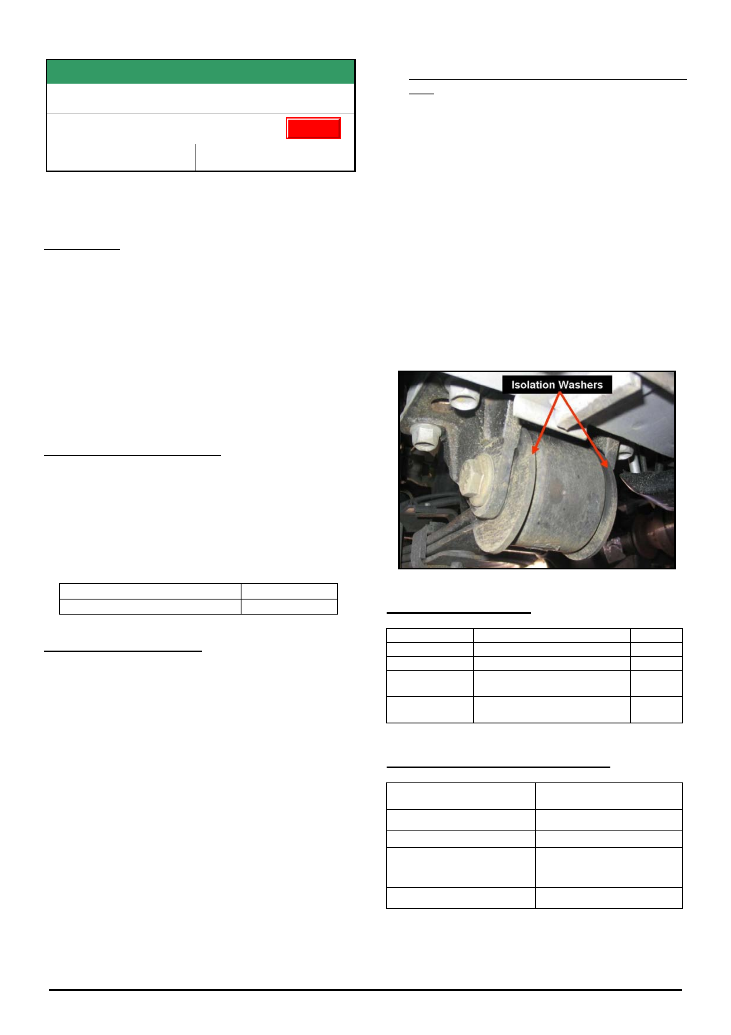
NOTE: There are four large washers p/n 92175916
that need to be fitted – one on each side of the front
spring eye bush as spacers/locators. These washers
are only fitted to vehicles with the revised spring eye
bushes.
5. For V8 (A/T & M/T) and V6(M/T) Rear Wheel Drive
Only: Revised pinion flange p/n 92176653 should
be fitted with a new nut p/n 92146565 exactly as
per procedure found in PV SIP:
Section 4B – Final Drive & Drive Shafts,
2. Minor Service Operations,
2.11 Pinion Flange / Replace using old seal.
CAUTION: Overtightening of the pinion nut may
result in excessive bearing preload and bearing
damage.
6. The alternative to Dealers doing step 5 is to
have a sublet repairer (diff specialist) fit the
flange. Any such repairer must use a torque
reading tension wrench to ensure the pre-load
before and after is the same - otherwise,
preload related noise/failure may occur at a
later date.
PARTS INFORMATION
Part No.: Description: Qty:
92148815 Bush Rr Spring Front 2
92175916 Washer 4
92176653 Pinion Flange
V8, and V6 (M/T only)
1
92146565 Flange Nut
V8, and V6 (M/T only)
1
WARRANTY CLAIM INFORMATION
Description Replace Bush, Leaf Spring
Front Eye – Both Sides
Labour Op. No. F000197
Time 1.6 hr.
Add for V8 & V6(M/T) Rear
Wheel Drive Only - Fitting
of revised Pinion Flange
0.5 hr.
Failure Code F0040 noisy
A/T – automatic transmission. RWD – Rear wheel drive
M/T – manual transmission AWD – All wheel drive
Update
HOLDEN SERVICE TECHLINES______________________________________________________________________________MARCH, 2006
10
Holden Techlines are written to inform technicians of conditions that may occur on some vehicles, and to provide information that could assist in the
proper service fix of a vehicle. If a condition is described, do not assume the service fix applies to a vehicle or that the vehicle will have that condition.
SERVICE FIX
Exhaust drone at 2500rpm
TT Zafira, TS Astra – Z22SE engine
Model Year 2003 & 2004
(GROUP 8) TL1085-0602
CONDITION
Customers may complain of an exhaust boom, drone
or resonance noticed at 2500rpm with the engine
under load.
CORRECTION - SERVICE
On customer complaint vehicles only, install a new
front engine pipe 55558954 which includes a revised
flex element. This will reduce the noise which arose on
model year 2003 and later vehicles when the exhaust
system was revised.
PARTS INFORMATION
Part No.: Description: Qty:
55558954 Exhaust Front Pipe 1
WARRANTY CLAIM INFORMATION
Use Labour Times information in Warranty Information
section of current PV SIP CD
SERVICE FIX
PCM, ECU, TCM, SPS Programming &
Instrument Cluster programming
All HSV models as follows -
VTII VX VY V2 VZ WH WK WL
Group 12 Ref. No. TL1084-0602
Please be aware that when replacing a PCM, ECU, TCM
or Instrument Cluster in the above mentioned HSV
models, the initial programming needs to be completed
by HSV.
Note that this only applies to NEW modules and NOT for
software updates, as TIS 2000 will allow updates once
the initial software is loaded by HSV.
To minimise the logistics of this procedure, contact HSV
on (03) 9265 9500 for their Technical Liaison personnel
to arrange for prompt parts programming and delivery.
HOLDEN SERVICE TECHLINES______________________________________________________________________________MARCH, 2006
11
Holden Techlines are written to inform technicians of conditions that may occur on some vehicles, and to provide information that could assist in the
proper service fix of a vehicle. If a condition is described, do not assume the service fix applies to a vehicle or that the vehicle will have that condition.
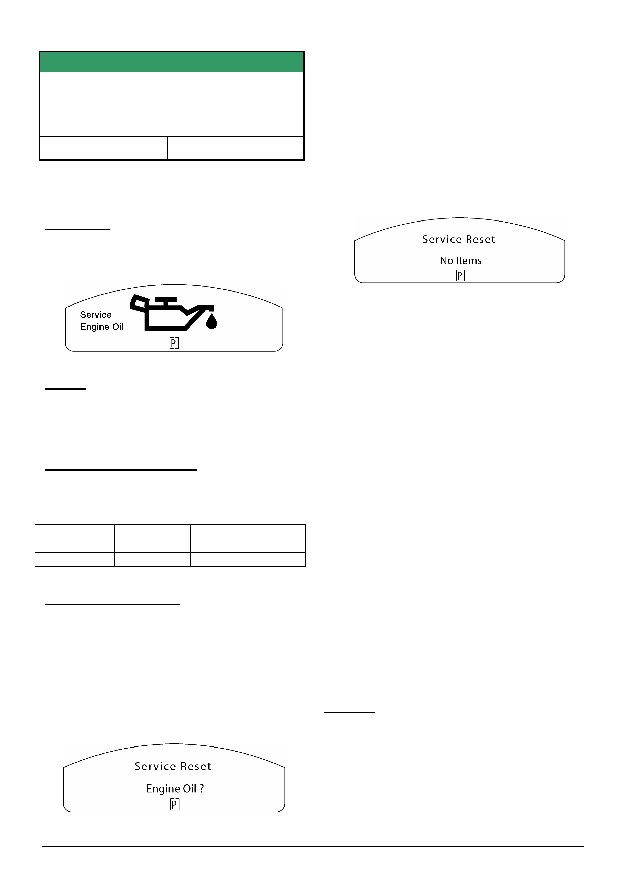
SERVICE FIX
“Engine Oil Life” Reset
VZ & WL HSV Gen 4 (LS2)
Group 12 Ref. No. TL1083 - 0602
When servicing any HSV vehicle fitted with an LS2
engine the “engine oil life” must be reset in the
engine control module using Tech 2 when the engine
oil is changed.
Failure to reset the engine oil life may result in the
following warning being displayed in the instrument
cluster when the ignition is cycled.
CORRECTION – Service
Summary
If this icon is displayed in the instrument cluster it will
be necessary to perform the following two procedures:
Instrument Cluster Service Engine Oil reset & Engine
Control Module “Engine Oil Life” reset.
If the vehicle is presented for scheduled servicing and
the “Service Engine Oil” icon is not displayed on the
instrument cluster it will only be necessary to perform
the Engine Control Module “Engine Oil Life” reset.
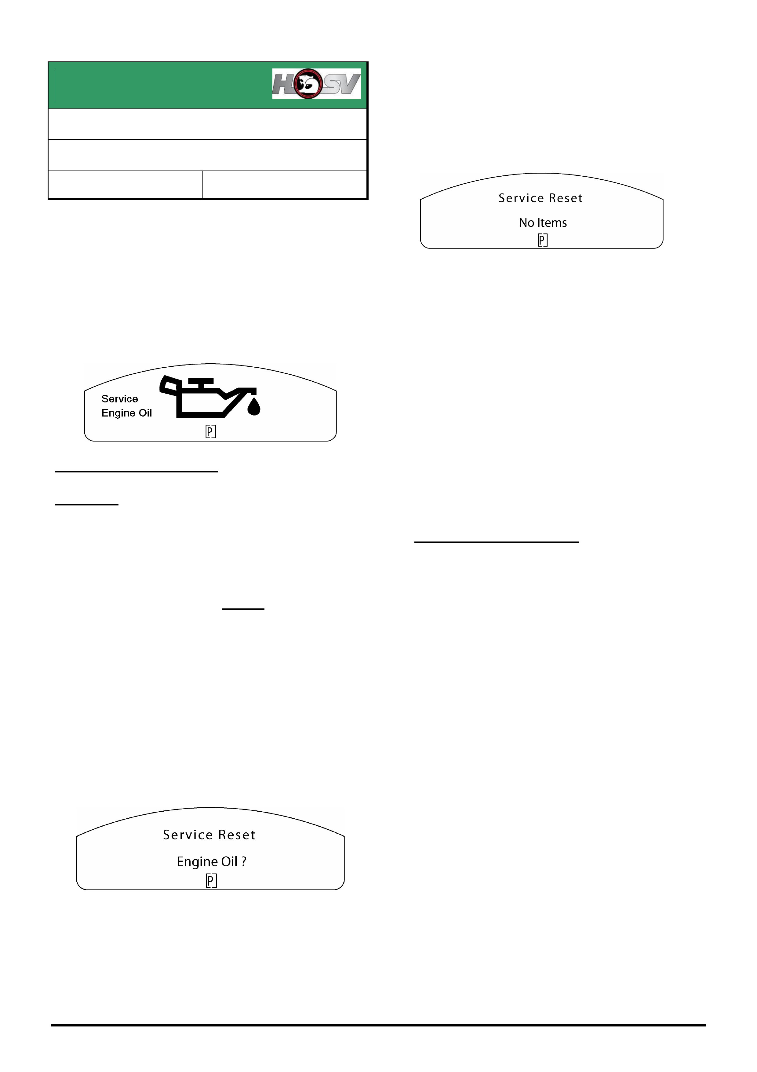
Instrument Cluster Service Engine Oil reset
procedure
If the above warning icon displays, the following
instrument cluster reset procedure must be performed.
1. Press and hold the up and down buttons on the
trip computer mode switch while turning the ignition
key on until a beep is heard, the following will be
displayed.
2. Press the set button on the trip computer mode
switch until a beep is heard (approx 8-10 seconds)
to reset the service item.
The display will then revert back to the start up
sequence.
If more than one service items are set, the next
service item will be displayed.
Press the set button on the trip computer mode
switch to reset the next service item if required.
3. The following will then be displayed.
Engine Control Module “Engine Oil Life” reset
procedure
1. Connect Tech 2 to the vehicle and make the
following selections,
F0: Diagnostics / Model Year / Vehicle Type /
F1: Engine / V8 Gen IV / F6: Programming /
F2: Reset Engine Oil Life
Select the “Yes” soft key
Select the “Confirm” soft key
SERVICE ADVISORS NOTE
If the “Service Engine Oil” icon appears between
scheduled services on a HSV Gen 4 (LS2) (and it
has been reset at the previous service) it may
indicate the vehicle is being used under extreme
conditions.
It may be necessary to discuss with your
customer the need for additional servicing.
For additional service requirements please refer
to the vehicle service booklet.
HOLDEN SERVICE TECHLINES______________________________________________________________________________MARCH, 2006
12
Holden Techlines are written to inform technicians of conditions that may occur on some vehicles, and to provide information that could assist in the
proper service fix of a vehicle. If a condition is described, do not assume the service fix applies to a vehicle or that the vehicle will have that condition.
SERVICE FIX
Service Engine Oil Warning Displays in the
Instrument Cluster.
VZ & WL excluding HSV Gen 4 (LS2)
Group 12 Ref. No. TL0890B - 0602
This Techline supersedes TL0890A-0503 in Issue 10, November
2005. It is UPDATED by adding new information for Service
Correction and Warranty Claims.
CONDITION
On some vehicles the “Service Engine Oil” warning
icon may display in the instrument cluster when the
ignition is cycled.
CAUSE
The “Service Engine Oil” feature which is not available
for the local market, has been inadvertently enabled in
the engine calibration.
CORRECTION – Production
Revised engine calibrations were introduced over a
one week period ending in the production breakpoint
below.
Engine Type Build Date: ISO VIN:
Gen III (LS1) 05/10/2005 6G1ZK14F96L516298
HFV6 2/12/2005 **********L535578
CORRECTION – Service
The following solution applies only to Gen III & HFV6
vehicles. The solution for HSV Gen 4 is published in
Techline # TL1083 – 0602 .
If the above warning icon displays, the following reset
procedure must be performed.
4. Press and hold the up and down buttons on the
trip computer mode switch while turning the ignition
key on until a beep is heard, the following will be
displayed.
5. Press the set button on the trip computer mode
switch until a beep is heard (approx 8-10 seconds)
to reset the service item.
The display will then revert back to the start up
sequence.
If more than one service items are set, the next
service item will be displayed.
Press the set button on the trip computer mode
switch to reset the next service item if required.
6. The following will then be displayed.
7. Re-program the ECU or PCM (engine or
powertrain control module) as per the standard SPS
(Service Programming System) process using Tech 2
and TIS 2000 version 69 or later.
NOTE: For detailed instruction on this process refer
to Holden Lionheart portal, Service Techlines,
Section OD – TIS, “Reprogramming Procedure –
Engine ECU / PCM SPS”.
8. Re-program the Instrument cluster as per the
standard SPS (Service Programming System) process
using Tech 2 and TIS 2000 version 65 or later.
NOTE: For detailed instruction on this process refer
to Holden Lionheart portal, Service Techlines,
Section OD – TIS, “Reprogramming Procedure –
Instrument Cluster SPS”.
9. Re-program the Fuel Gauge Calibration in the
instrument cluster using Tech 2 software version
14.502 or later from TIS 2000 version 65 or later.
NOTE: For detailed instruction on this process refer
to Holden Lionheart portal, Service Techlines,
Section OD – TIS, “Reprogramming Procedure –
Instrument Cluster Fuel Gauge calibration”.
CAUTION:
Software downloaded from TIS 2000 CD 65 or later is
not compatible with old instrument cluster software,
old engine ECU / PCM software or old fuel gauge
calibration from earlier releases of TIS 2000.
Therefore these three files must be used as a set
whenever programming an engine control module,
instrument cluster or fuel gauge calibration.
HOLDEN SERVICE TECHLINES______________________________________________________________________________MARCH, 2006
13
Holden Techlines are written to inform technicians of conditions that may occur on some vehicles, and to provide information that could assist in the
proper service fix of a vehicle. If a condition is described, do not assume the service fix applies to a vehicle or that the vehicle will have that condition.
WARRANTY CLAIM INFORMATION
Description Service Engine Oil
Warning
Labour Op. No. J000791
Time V8 - 0.4 hrs
V6 - 0.5 hrs
Failure Code J0057
NOTE: Labour operation number and time covers
instrument cluster, ECU / PCM and fuel gauge re-
programming.
INFORMATION
Coolant Usage/Replenishment Precaution
JF Viva & TK Barina
Group 6K Ref. No. TL1088 - 0602
Technicians should be aware of the possible coolant
colours and specifications for these models.
When replacing coolant, refer to the Vehicle Owner
Handbook information.
(Refer to TK Barina handbook information as follows)
Coolant specification
(if coolant is ORANGE/RED)
50%Clean water and 50% Extended life
anti-freeze Coolant (orange) conforming
to Holden Spec.GM6277M
Part Number 92145527(5 litre)
Coolant specification
(if coolant is BLUE)
50% Clean water and 50% Silicate
Coolant(green), conforming to
Holden Spec HN 2217
When replacing or replenishing coolants please note
the following:
- Orange & Red coolant can be mixed;
- Blue & Green coolants can be mixed.
DO NOT mix any other combinations of these coolants
or cooling system damage may result.
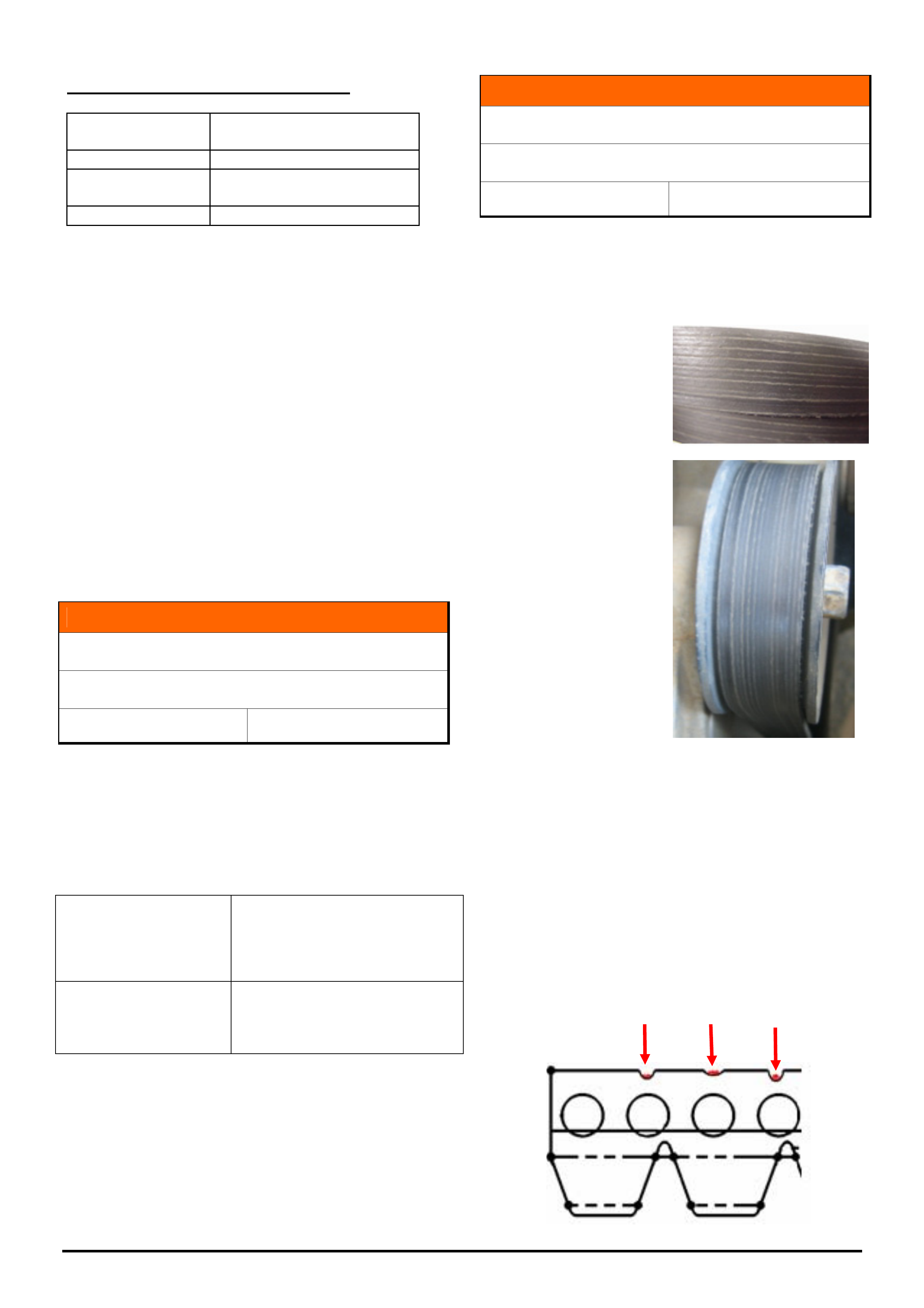
INFORMATION
Drive Belt “Excessive Wear” Appearance
VZ & WL with LS1 or LS2 V8
Group 6A Ref. No. TL1043 - 0602
Technicians (or customers) may believe that drive
belts are “excessively worn” when the belt backing
discolours or develops “stripes” or “lines” - evident at
the back of the belt as shown below:
On belt surface:-
On belt, as fitted to
an engine:
DO NOT replace belts because of this discoloration or
the “lines” or “stripes” that are evident
This is normal wear and tear from dust being trapped
between the back of the belt and idler pulleys, etc. –
and may occur more rapidly when a vehicle is driven in
dusty areas.
Discoloration is from imbedded dirt which also
increases the visibility of the back side indentations
which are inherent in the construction of this type of
belt. The “lines” coincide with pressure points created
by the belt inner reinforcing cords as in this sketch:

HOLDEN SERVICE TECHLINES______________________________________________________________________________MARCH, 2006
14
Holden Techlines are written to inform technicians of conditions that may occur on some vehicles, and to provide information that could assist in the
proper service fix of a vehicle. If a condition is described, do not assume the service fix applies to a vehicle or that the vehicle will have that condition.
INFORMATION
Holden Contacts and procedures
All
Group OB Ref. No. TL0679B-0602
This Techline supercedes the previous one (TL0679A-0501) in
Issue 1, Feb 2005. It contains UPDATED information.
This techline summarises some of the Holden contact
procedures and gives a quick reference guide for
contact numbers.
Security information.
To obtain security information for both Passenger and
LCRV vehicles the first step is to check the New Online
Warranty system (NOW). If the information is
unavailable on NOW then a completed security
information request form must be faxed through to the
Vehicle Security Information Centre, as security
information cannot be given out by phone. Please note
that security information requests are processed by the
Vehicle Security Information Centre and not TAS.
To ensure you have the latest security information
request form always refer to Service Forms in the
Service Bulletin section of the Holden Lionheart Portal.
Fax completed forms to the Vehicle Security
Information Centre on fax 03-96472865.
There can be up to a 4-hour turn around on requests,
however if the information needs to be obtained from
overseas, it may take up to 24 hrs. Do not phone the
security information department unless you have not
received a response in the normal turn around time.
For further information please refer to ADL 42/05.
Accessories and parts inquiries
If any information or assistance is required in regards
to Microcat, part numbers, Holden accessories or if
you need to contact HSPO Customer Assistance,
please refer to the Holden Help section in Microcat.
Warranty Authorisation and enquiries
Warranty can only be authorised by your Aftersales
District Manager. Labour times information is available
on SIP or from the warranty department. For any other
warranty inquiries please contact Warranty
Administration.
TAS
Technical Assistance Service (TAS) is a service
provided by Holden to assist Holden Dealers in
problem resolution.
Contact to TAS must be made by a Nominated Contact
as outlined in Section 5 of the TAS procedures
manual. All techlines, dealer letters and service
information must be checked prior to contacting TAS.
The Nominated Contact must not contact TAS until
he/she has been fully involved with the faulting vehicle
and all Dealer expertise has been exhausted.
Problems should be escalated through the Dealership
to the senior technician/foreman before contacting
TAS.
TAS cases must be updated or closed within 30 days
unless a Dealer is waiting on a service fix to be
provided. It is the Dealers responsibility to update
cases. All cases should be recorded in the TAS
procedures manual, which should be referred to prior
to contacting TAS. Please note that an electronic copy
of the TAS procedures manual is also available on
passenger SIP.
Under no circumstances are TAS or other Holden
contact details to be supplied to customers or
independent repairers. TAS is a service restricted to
assisting Holden Dealer service departments.
Quick reference contact numbers
Autostrada Ph 1800 634 343
Air International Ph 1800 673 716
Australian Arrow Ph 03 9785 0792
Blaupunkt Ph 1300 307 036
Bosch Technical Assistance Ph 1800 025 462
Clarion Ph 1300 730 730
Fax 03 9551 0377
Customer Assistance Ph 1800 033 349
Dana Ph 02 9892 9237
Ph 02 9892 9343
Fax 02 9892 9310
www.spiceraxle.com.au
HBD DVD support (Delphi) Ph 03 8558 8313
Eurovox Ph 03 9237 0800
Fujitsu Ten Ph 03 9646 6008
Holden Assist Ph 1300 880 088
Hollandia/Webasto sunroof Ph 02 9540 4811
Fax 02 9540 4316
HSV Ph 03 9265 9500
Impco Ph 03 9584 5644
Infomedia (SIP, Partfinder) Ph 1800 810 103
Lumen Ph 03 8787 1000
Panasonic Ph 02 9986 7635
PBR Diagnostic assistance Ph 1800 468 727
Petro-Ject Ph 02 9890 5701
Ph 02 9890 5244
Philips/Siemens-VDO Ph 1800 335 282
Salmat Ph 03 9358 2900
Security Information Ph 03 9647 2001
Fax 03 9647 2865
SPX Australia Ph 03 9544 6222
TAS Ph 1800 033 417
Fax 03 9647 2495
Email [email protected]
Triple M Ph 1800 773 030
Warranty Ph 1800 033 487
HOLDEN SERVICE TECHLINES________________________________________________________________________________APRIL, 2006
4
Holden Techlines are written to inform technicians of conditions that may occur on some vehicles, and to provide information that could assist in the
proper service fix of a vehicle. If a condition is described, do not assume the service fix applies to a vehicle or that the vehicle will have that condition.
INFORMATION
Convex Mirrors On Driver’s Side
XC Tigra, TK Barina sedan,
Group 1 Ref. No. TL1098 - 0603
Some dealers report they are seeing new models such
as the above, being delivered with convex** type
external mirrors on the drivers side.
NOTE: A recent change in Australian Design Rules
(ADR’s) has now made it possible for new vehicles to
be built with “convex” mirrors on both sides of the
vehicle.
Therefore, DO NOT REPLACE the drivers side mirror
on these new vehicles thinking that they have not been
built to specification.
** Convex mirror – Objects viewed in this type of mirror
are actually closer than they appear.
DIAGNOSIS HINT
Replacement Body Control Modules (BCM)
sourced from HSPO
All V & W cars
(GROUP 12) TL1103-0603
TAS continue to receive many calls from dealers who
say they are unable to link a new replacement BCM to
the PCM/PIM.
This problem will occur if the BCM has been sourced
from HSPO and the dealer is still using the original
remotes. It is a mandatory requirement that both
remotes are replaced whenever the BCM is
sourced from HSPO.
TIP: If Tech 2 asks you to “disarm the theft deterrent
with a programmed remote key”, this is an indication
that you have not replaced the remotes or
programmed them first.
If the BCM is obtained under warranty through the
changeover program, the original remotes are to be
used (unless specified otherwise).
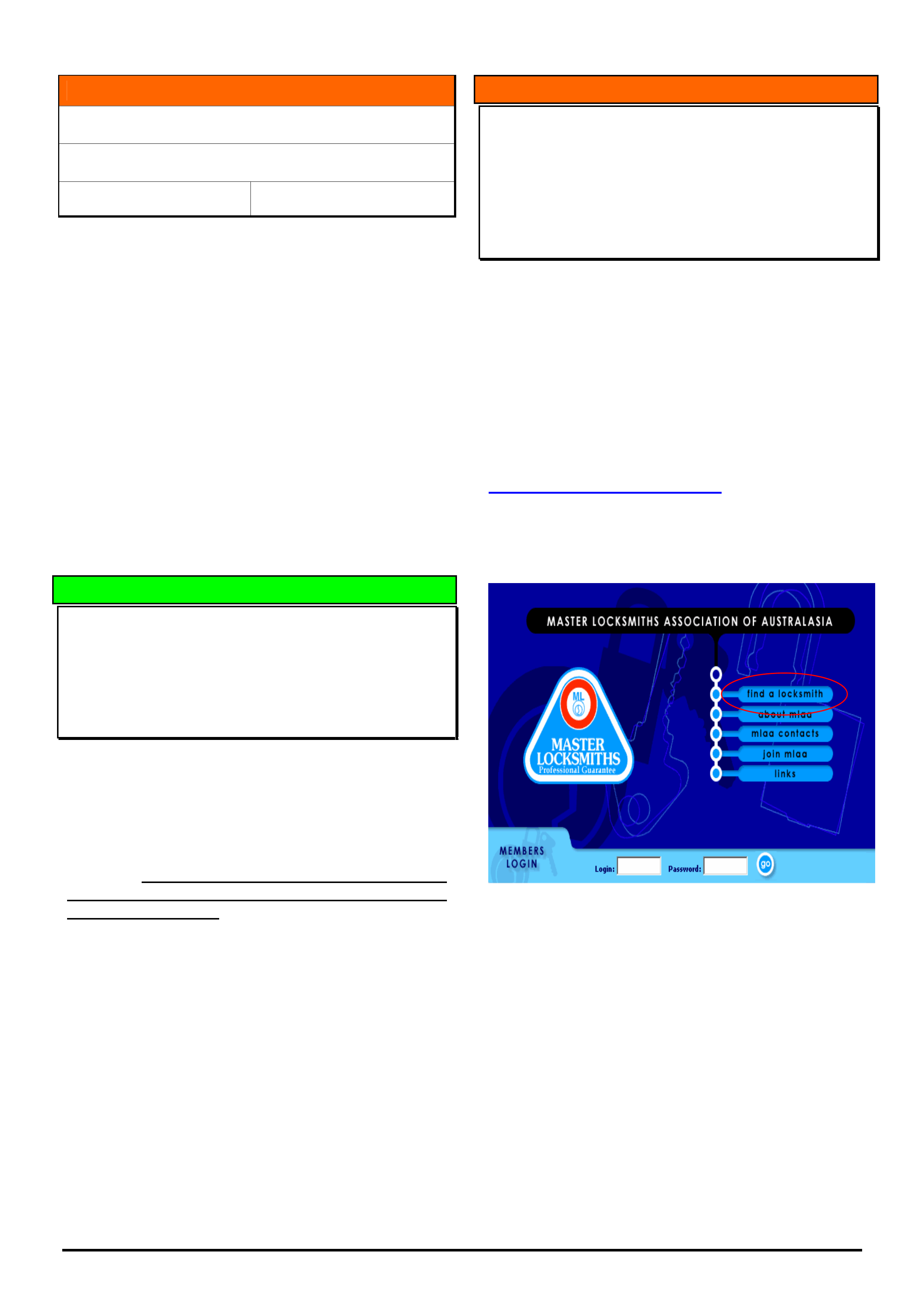
INFORMATION
Finding Locksmiths to cut ‘Z’ (snake) profile
keys
MY 2005 onwards – XC Barina, TS Astra, AH
Astra, ZC Vectra, TIGRA
(GROUP OB) TL1089-0603
As of model year 2005, some of our imported vehicles
have what is called a ‘Z’ or ‘snake’ style door/ignition
key profile.
As specialised equipment is required to cut this type of
key, some locksmiths may not be able to do this.
Following, is one example of a web site link that may
assist dealers to contact a locksmith in their area to
ensure they can cut this type of key.
www.masterlocksmiths.com.au
From the home page as shown, select ‘find a
locksmith’, choose Australia or New Zealand as
required and follow the prompts.
HOLDEN SERVICE TECHLINES________________________________________________________________________________APRIL, 2006
5
Holden Techlines are written to inform technicians of conditions that may occur on some vehicles, and to provide information that could assist in the
proper service fix of a vehicle. If a condition is described, do not assume the service fix applies to a vehicle or that the vehicle will have that condition.
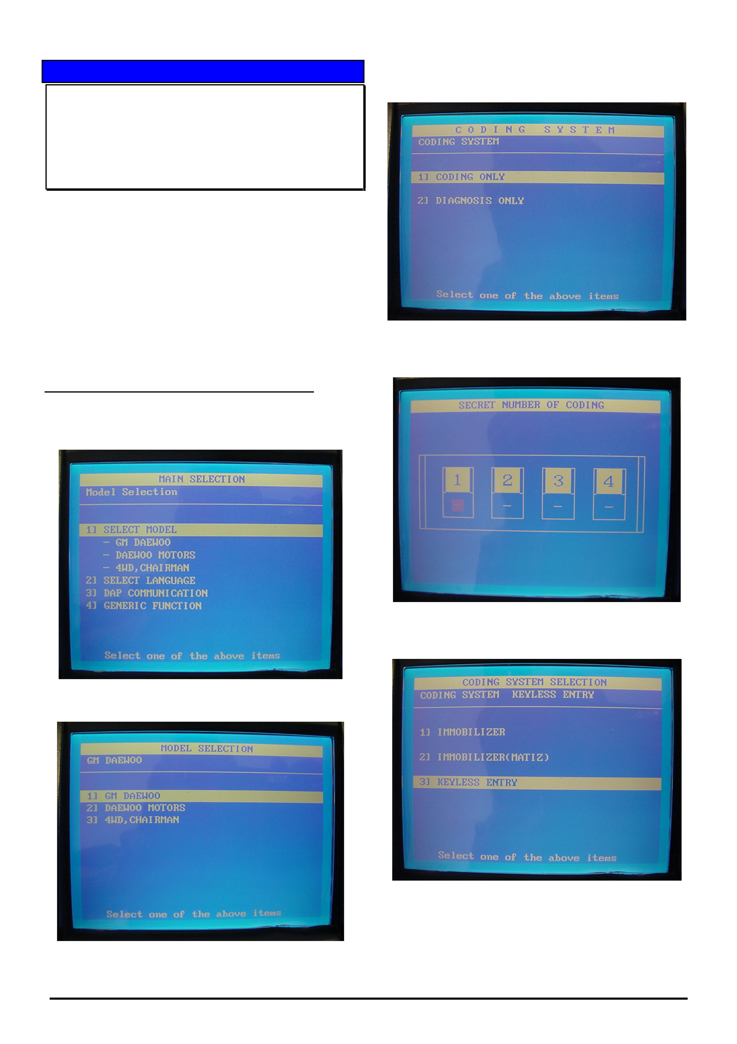
SERVICE PROCEDURE
Keyless Entry Remote Key Programming
Daewoo Leganza With Factory Fitted Keyless
Entry System
(GROUP 12) TL1096-0603
To program the remote key for the keyless entry system
you will need a Scan 100 tool.
Dealers who do not possess a Scan 100 tool will need to
obtain one on loan from their Zone office.
NOTE: There is no option on Tech 2 to program the
remote key for the keyless entry system on this model
as this function has not been written into the Tech 2
Software.
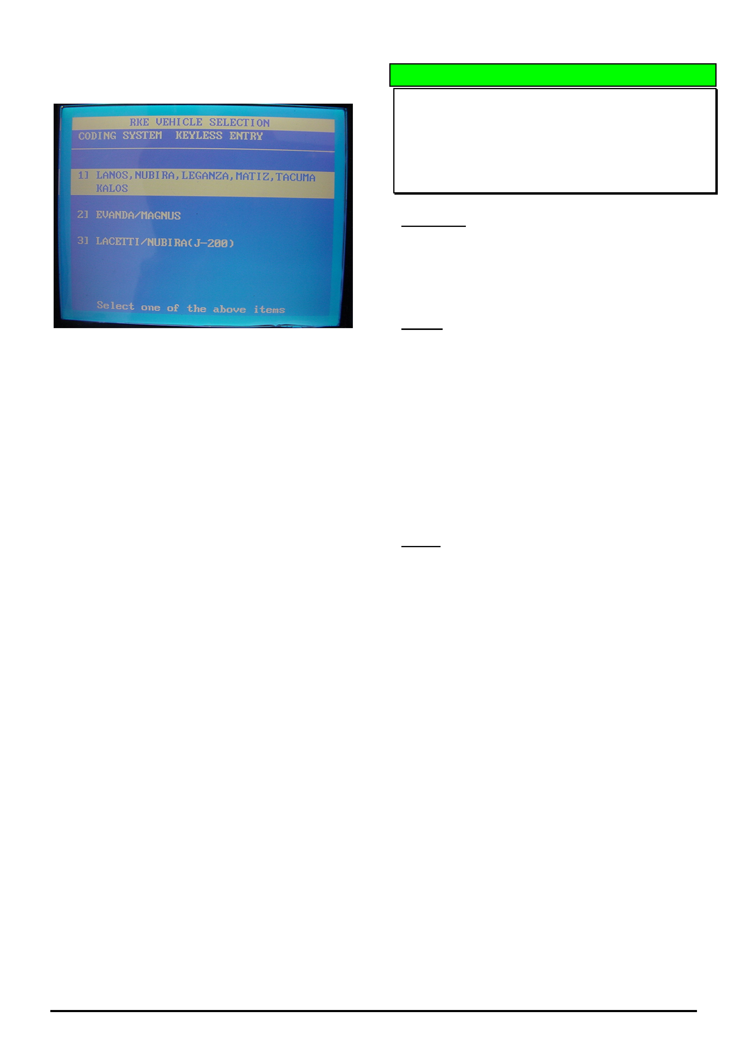
Programming Procedure using SCAN-100
1. From the Model Selection screen select
“GM DAEWOO” then press enter
2. From the Coding System screen select “CODING
ONLY” then press enter
3. Enter the “secret number” using 0 0 0 0
4. Select “KEYLESS ENTRY” then press enter
HOLDEN SERVICE TECHLINES________________________________________________________________________________APRIL, 2006
6
Holden Techlines are written to inform technicians of conditions that may occur on some vehicles, and to provide information that could assist in the
proper service fix of a vehicle. If a condition is described, do not assume the service fix applies to a vehicle or that the vehicle will have that condition.
5. Select Lanos, Leganza, Matiz, Tacuma, Kalos
then press enter
6. After selection of this screen continue to follow the
prompts as shown on the Scan 100.
DIAGNOSIS HINT
Instruments Customisation Mode Options
Missing
VY,VZ, WK,WL
(GROUP 12) TL1090-0603
Condition
Customer advises that when selecting the
customisation mode within the multi function display
(MFD) of the Instrument cluster, some features as
described in the Owners Handbook are no longer
available.
Cause
TAS cases have shown this symptom occurs after the
customer has fitted an aftermarket accessory radio.
Because the genuine (factory fitted) radio
communicates on the serial data bus, it needs to be
present in order to display all of the audio features
within the MFD. Therefore, the genuine radio must be
refitted to display ALL previous options.
If this is not possible, it must be explained to the
owner/installer that the serial data circuit must remain
open with nothing connected to it or other
communications issues may arise.
NOTE: Any faults which arise as a result of fitting
aftermarket (non genuine) accessories as described
above are not covered under warranty.
HOLDEN SERVICE TECHLINES________________________________________________________________________________APRIL, 2006
7
Holden Techlines are written to inform technicians of conditions that may occur on some vehicles, and to provide information that could assist in the
proper service fix of a vehicle. If a condition is described, do not assume the service fix applies to a vehicle or that the vehicle will have that condition.
INFORMATION
HSPO Replacement Seat Base Assemblies
VZ, WL
Group 1 Ref. No. TL1097- 0603
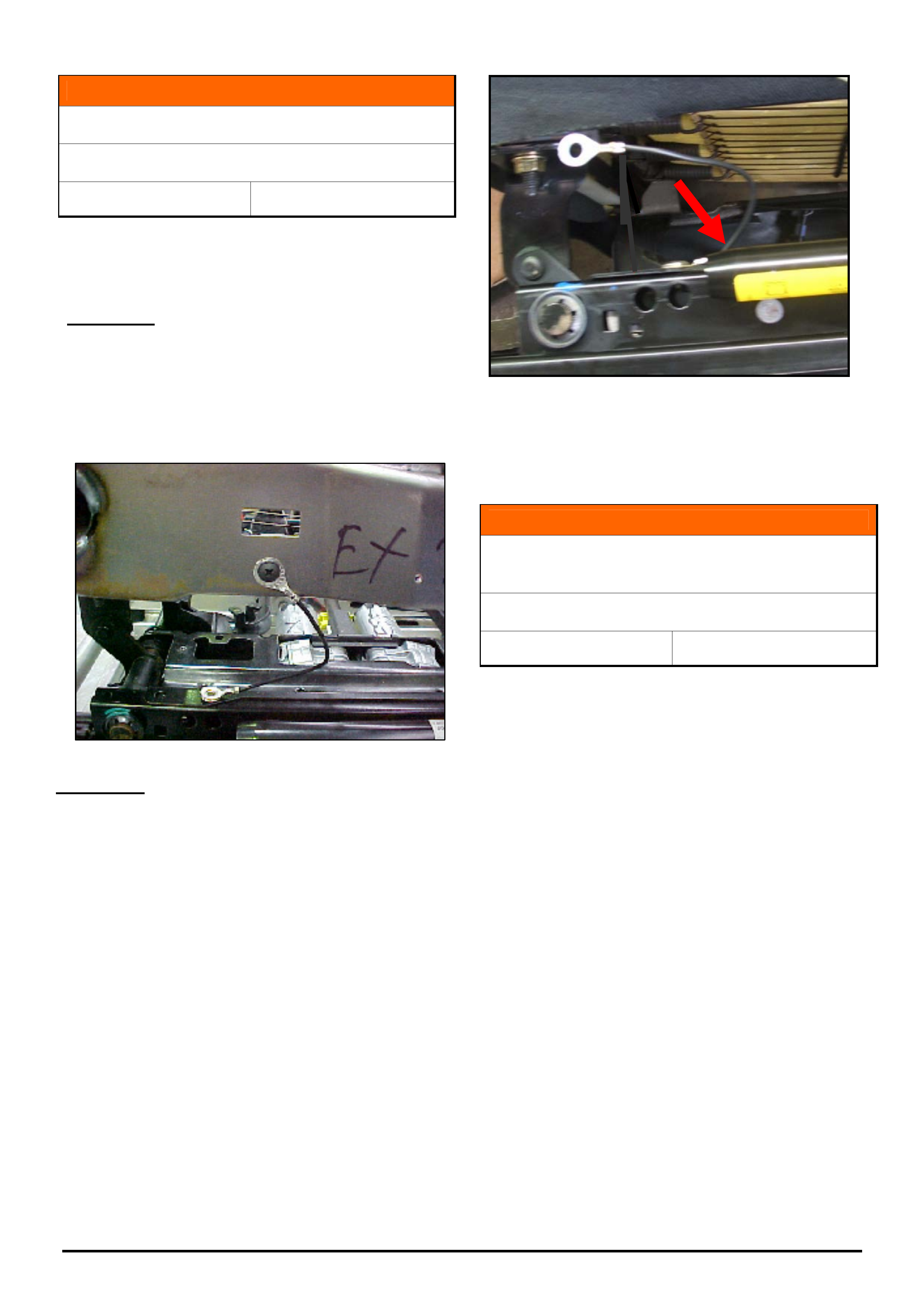
Some replacement HSPO front seat base assemblies
may have an earth lead attached to the inner seat
track as shown in Figure 2.
Situation A. - Existing seat base has an earth lead
attached.
If you are supplied with a replacement seat base with
an earth lead attached which is replacing a seat base
that already has an earth lead attached, then simply
replace the seat base and reattach the earth lead to
the location provided in the seat cushion frame as
shown in Figure 1.
Figure 1
Situation B. Existing seat base DOES NOT have an
earth lead
If you are supplied with a replacement seat base with an
earth lead attached which is replacing a seat base that
does not have an earth lead attached proceed as
follows:
1. Remove the earth lead by cutting the wire as close
to the inner track as possible as shown in Figure 2.
(DO NOT ATTEMPT TO DRILL OUT THE RIVET)
2. Replace the seat base as per PV SIP instructions.
3. After installation of the seat base assembly, fit a
seat base to seat frame earth spring (Part No.
92190159), as per Product Campaign 06-H-02.
NOTE: On vehicles where the campaign has
previously been completed, ensure the earth
spring is reinstalled correctly. Refer to product
campaign 06-H-02 bulletin for details of correct
fitment.
Figure 2.
INFORMATION
Use Of Accessory Cargo Barrier With Factory
Fitted LPG
VZ Wagon
Group OB Ref. No. TL1101 - 0603
The genuine Holden accessory cargo barrier cannot
be fitted on vehicles with factory fitted LPG (option
code LW2).
When the spare wheel is relocated it intrudes into the
space that the cargo barrier would normally occupy.
Microcat is currently being updated to show that the
cargo barrier cannot be fitted on vehicles with factory
fitted LPG.
HOLDEN SERVICE TECHLINES________________________________________________________________________________APRIL, 2006
8
Holden Techlines are written to inform technicians of conditions that may occur on some vehicles, and to provide information that could assist in the
proper service fix of a vehicle. If a condition is described, do not assume the service fix applies to a vehicle or that the vehicle will have that condition.
DIAGNOSIS HINT
Intermittent Loss of Sound from the Audio
System
WK, WL, Caprice
Group 12 Ref. No. TL1102 - 0603
Customers may advise the sound from the audio
system intermittently drops out.
The following information has been received via dealer
PIR’s and is published to minimise diagnosis time
when investigating problems related to the above
symptom.
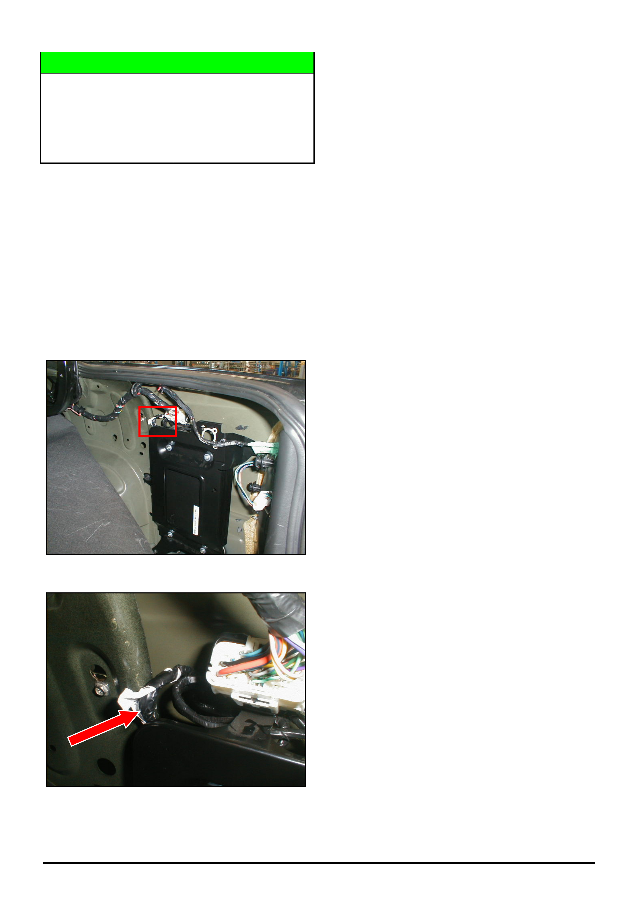
Inspect the wiring in the right hand rear quarter panel
next to the premium sound amplifier for wiring damage
(short to ground) in the location highlighted in figure 1
and figure 2.
Figure 1
Figure 2
If damage is discovered, repair the damaged circuits
and re-insulate to avoid a repeat failure.
See Figure 2
HOLDEN SERVICE TECHLINES________________________________________________________________________________APRIL, 2006
9
Holden Techlines are written to inform technicians of conditions that may occur on some vehicles, and to provide information that could assist in the
proper service fix of a vehicle. If a condition is described, do not assume the service fix applies to a vehicle or that the vehicle will have that condition.
SERVICE FIX
DTC P1106 “Boost Pressure Control Device
Malfunction”
TS Astra Z20LET
Group 12 Ref. No. TL1099 - 0603
CONDITION
Customers may advise the CEL light illuminates.
When Tech 2 is connected DTC P1106 “Boost
Pressure Control Device Malfunction” is set in the
engine ECU.
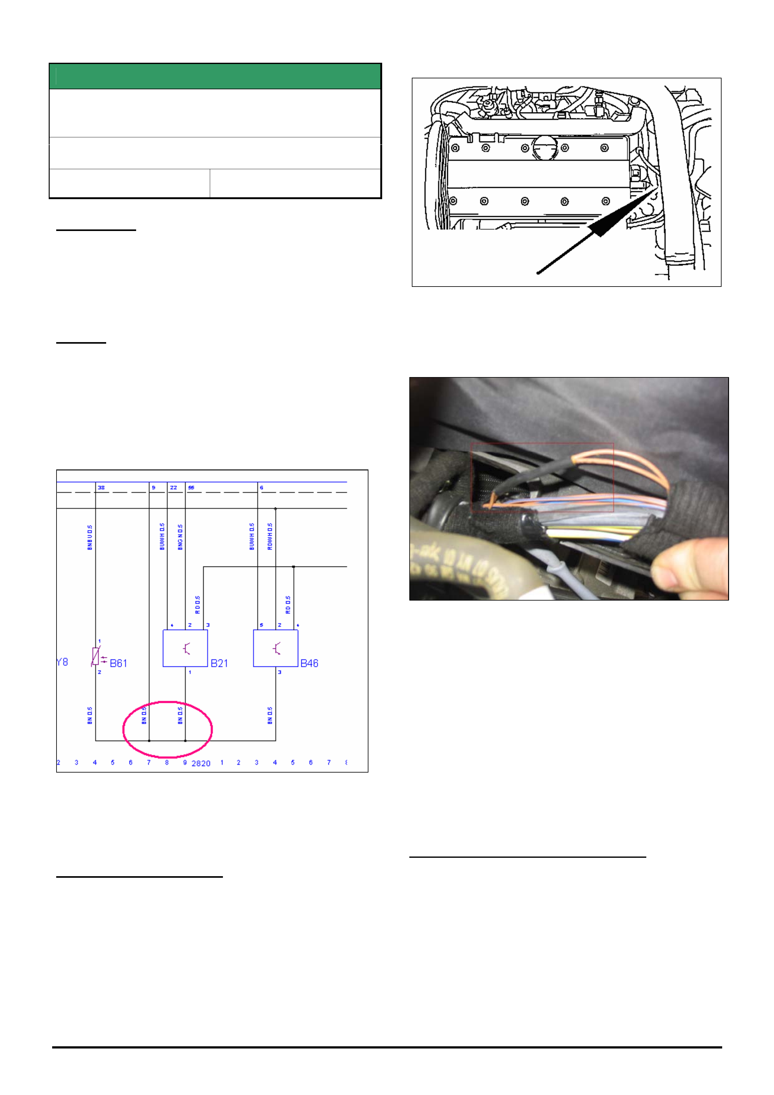
CAUSE
The cause of this condition may be a poor connection
in an earth splice joint within the engine harness (refer
circuit diagram in figure 1).
This splice joint provides an earth for the Coolant
Temp Sensor (B61), Intake Manifold Absolute
Pressure Sensor (B21) and the Air Mass Meter (B46).
Figure 1
CORRECTION – Service
Confirm DTC P1106 is set in the engine ECU either
history or present.
5. Locate the section of the engine harness indicated
in figure 2, on the passenger’s side of the engine
bay under the intake hose, next to the battery.
Figure 2.
6. Remove the tape from this section of the engine
harness and locate the splice joint shown in figure 3.
Figure 3
7. Remove the suspect splice joint (under the black
heat shrink in figure 3, from the harness and
renew the splice joint. Reconnect the four earth
circuits.
Note: If unsure of the approved method of wiring
repair refer to PVSIP VZ / Wiring Diagrams / Section
12P / 5. Wiring Repair Procedure / 5.3 Splicing Wiring
Using Spice Clips.
8. Re-insulate the splice joint after repair and re-tape
the engine harness.
WARRANTY CLAIM INFORMATION
Use Labour Times information in Warranty Information
section of current PV SIP disc.
HOLDEN SERVICE TECHLINES________________________________________________________________________________APRIL, 2006
10
Holden Techlines are written to inform technicians of conditions that may occur on some vehicles, and to provide information that could assist in the
proper service fix of a vehicle. If a condition is described, do not assume the service fix applies to a vehicle or that the vehicle will have that condition.
INFORMATION
Searching for Service Information on Holden Dealer Portal - “Lionheart”
(GROUP OB) TL0921A-0603
( This Techline supercedes the previous one in Issue 5, June 2005. It is UPDATED with the latest procedure. )
This Techline describes how to find the following Service Information on the Holden Dealer Portal - “Lionheart”.
• Service Techlines
• All Dealer Letters
• Campaign Bulletins
• Field reworks
• Warranty Processing
• Special Warranty Component Replacements
• Service Forms.
PROCEDURE.
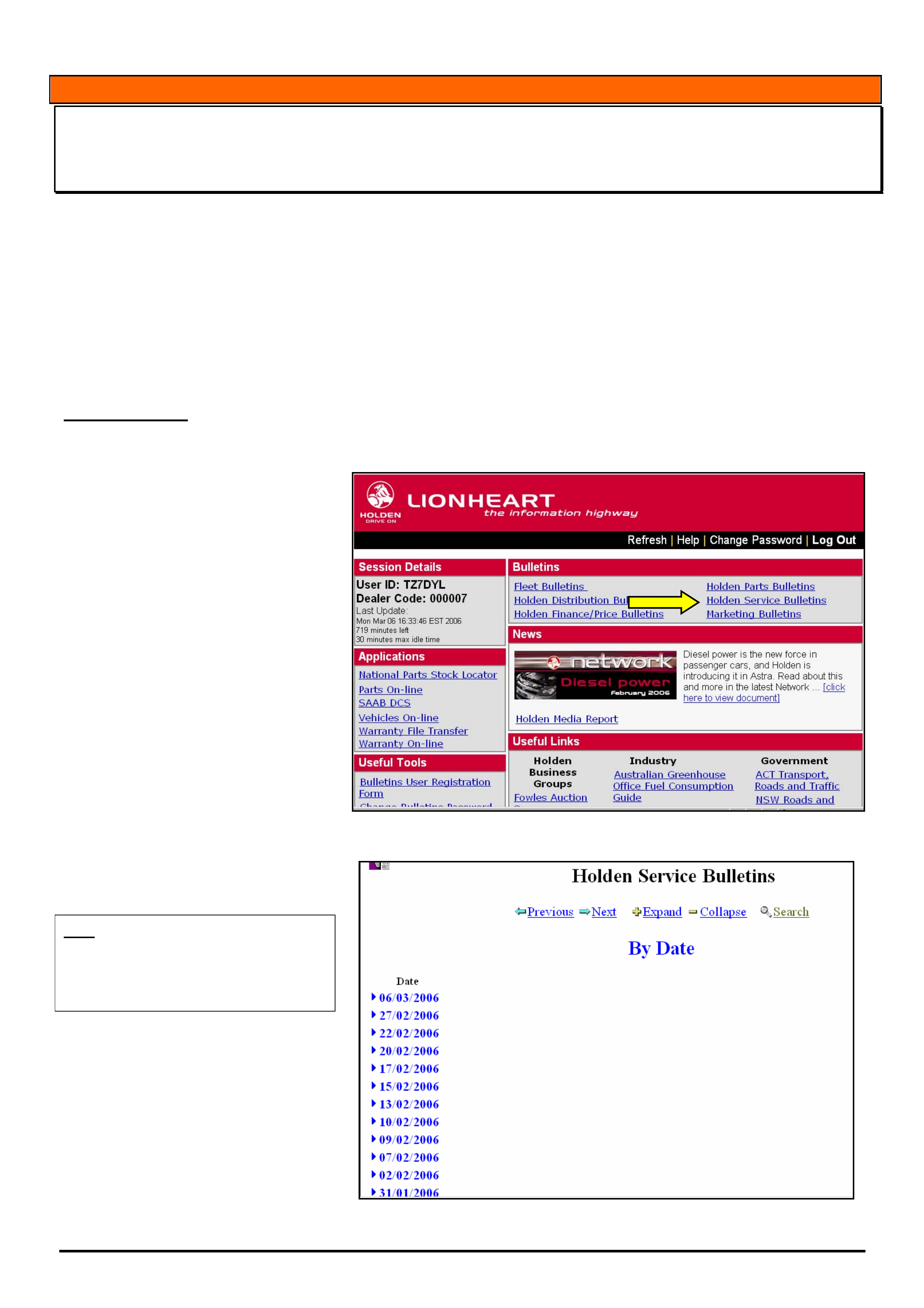
When you logon to the Holden Portal the Lionheart Home page will appear as shown in Figure 1.
Now select “Holden Service Bulletins”
as indicated by yellow arrow.
.
Figure 1
The next screen to appear is shown in
Figure 2.
HINT: This screen should be thought of as
an email inbox.
You should check this screen everyday to
view the latest information issued by
Holden Service Department.
The date at the top of the list is when
the newest bulletins were posted onto
Lionheart. In the example in Figure 2
this date is 06/03/2006.
Figure 2.
HOLDEN SERVICE TECHLINES________________________________________________________________________________APRIL, 2006
11
Holden Techlines are written to inform technicians of conditions that may occur on some vehicles, and to provide information that could assist in the
proper service fix of a vehicle. If a condition is described, do not assume the service fix applies to a vehicle or that the vehicle will have that condition.
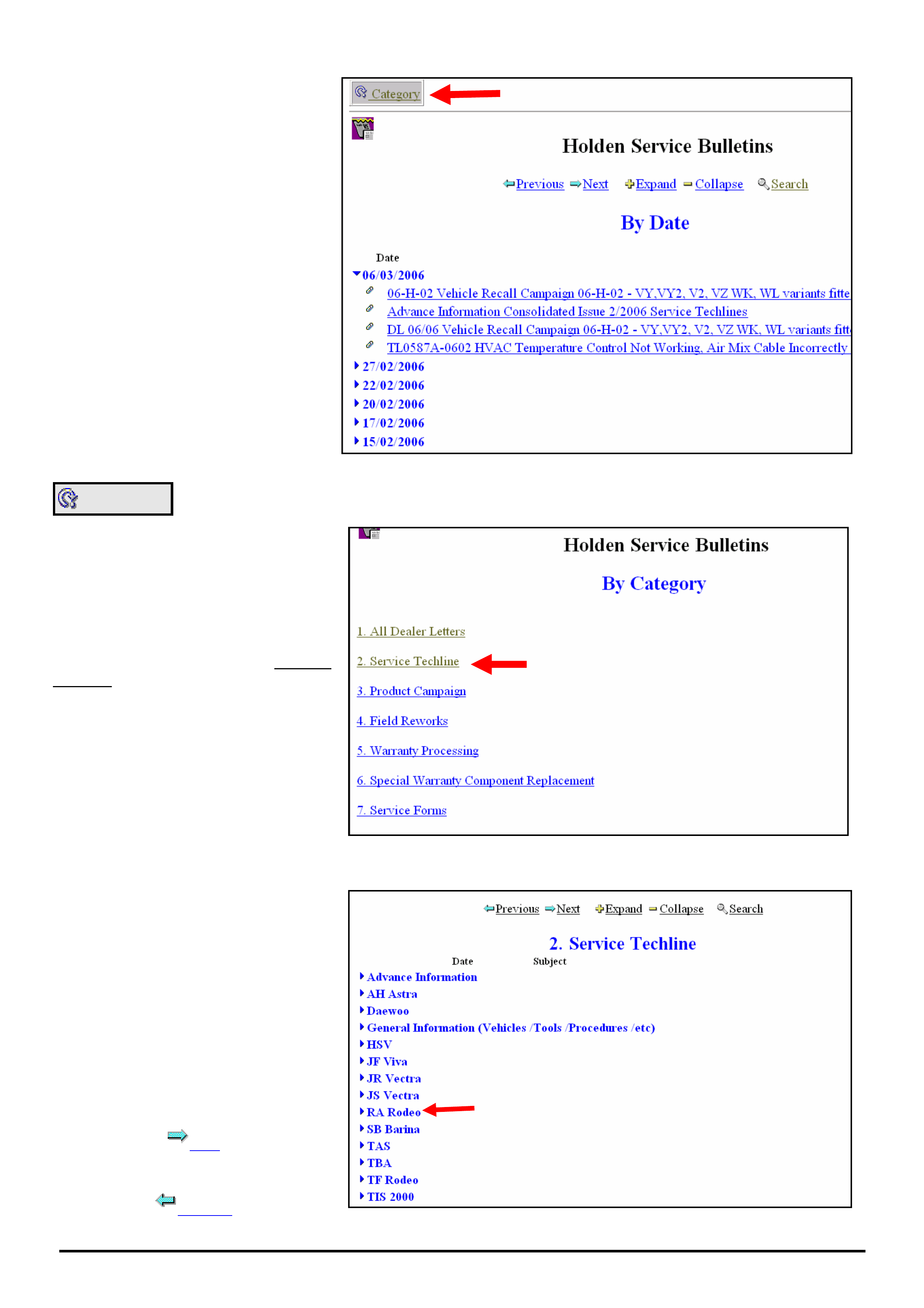
To view the bulletins for the 06/03/2006,
click on the “►” symbol next to the date
and a list of bulletins will appear as
shown in Figure 3.
To view any bulletin click on it.
Figure 3.
Category
If you select the “Category” button as
indicated by the red arrow in Figure 3
the screen shown in Figure 4 will
appear.
Now select the category you want.
As an example, select “Service
Techline”
The next screen to appear is shown in
Figure 5.
Figure 4
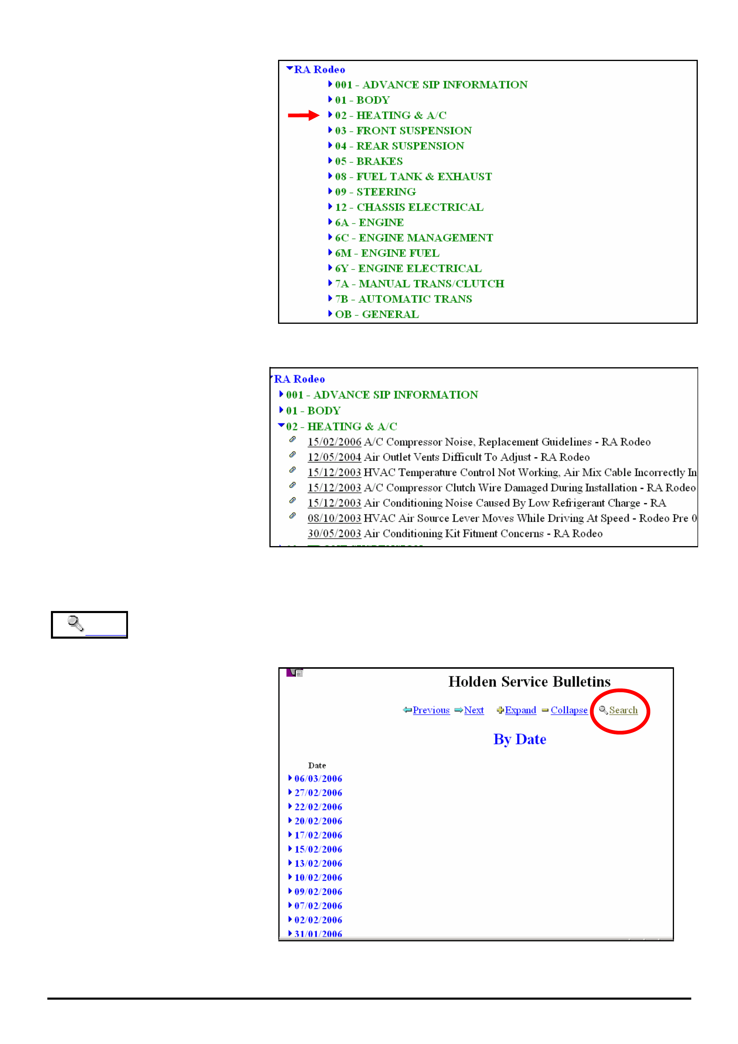
From this screen you select the model
you are interested in.
For example, click on the “►” next to
RA Rodeo
The next screen to appear is shown in
Figure 6.
NOTE: To view the full list of models
you will need to turn over to the next
page by clicking on the “next” arrow at
the top or bottom of the screen
Next
To go back a screen, press “previous”
Previous
Figure 5
HOLDEN SERVICE TECHLINES________________________________________________________________________________APRIL, 2006
12
Holden Techlines are written to inform technicians of conditions that may occur on some vehicles, and to provide information that could assist in the
proper service fix of a vehicle. If a condition is described, do not assume the service fix applies to a vehicle or that the vehicle will have that condition.
Now select the Group you are interested
in.
Example - select 02-HEATING & A/C
The next screen to appear is shown in
Figure 7.
Figure 6.
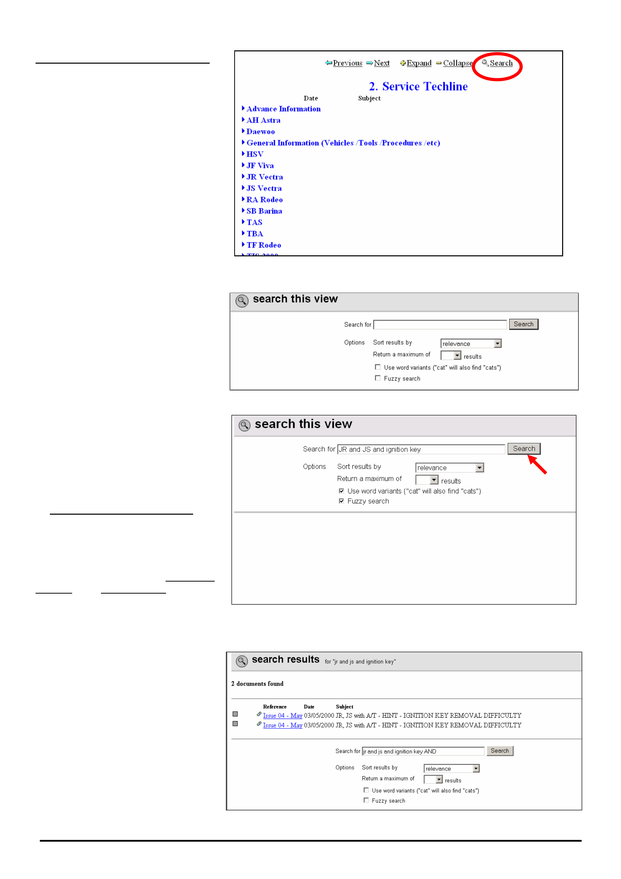
Now look through the list of Techlines
to find the one you are interested in.
NOTE: Techlines are arranged in
order of date with the newest at top of
list.
Figure 7.
Search USING THE SEARCH METHOD TO FIND INFORMATION ON LIONHEART
If you select the SEARCH function
from the screen in Figure 8 it will
search through all the Service
Information Categories as follows:
• Service Techlines
• All Dealer Letters
• Campaign Bulletins
• Field reworks
• Warranty Processing
• Special Warranty Component
Replacements
• Service Forms.
To shorten the search process, select
the SEARCH function only after you
are in the particular category you are
interested in.
Following, is a description of how to
search for Service Techlines.
Figure 8
HOLDEN SERVICE TECHLINES________________________________________________________________________________APRIL, 2006
13
Holden Techlines are written to inform technicians of conditions that may occur on some vehicles, and to provide information that could assist in the
proper service fix of a vehicle. If a condition is described, do not assume the service fix applies to a vehicle or that the vehicle will have that condition.
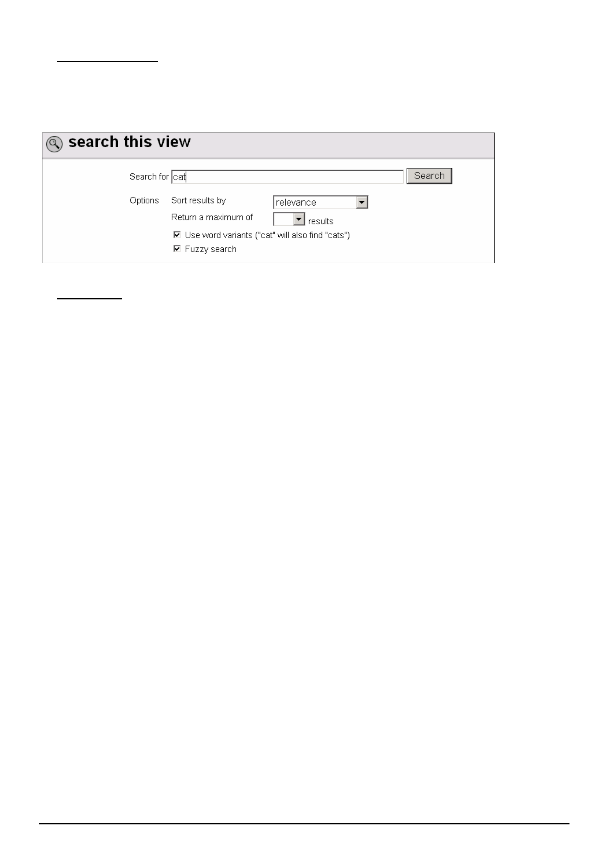
Searching for Service Techlines
From the screen shown in Figure 9
click on the “Search” key. This will
bring up the screen shown in Figure
10.
Figure 9
This is the search screen used for
entering “keywords” to search for.
It is important to enter the right words
here in order to find what your looking
for.
Figure 10
As an example (Figure 11) try
searching for Techlines related to JR
& JS Vectra Ignition Barrel
Jamming.
In the top window, type in the following
“search string” exactly as shown.
“JR and JS and Ignition key”.
Don’t touch the next 2 boxes titled
“Sort results by” or,
“Return a maximum of”.
Tick the last 2 boxes i.e. Use Word
variants and Fuzzy search. Refer to
later explanations of these terms.
Now click the “Search” button. Shown
with the red arrow.
Figure 11
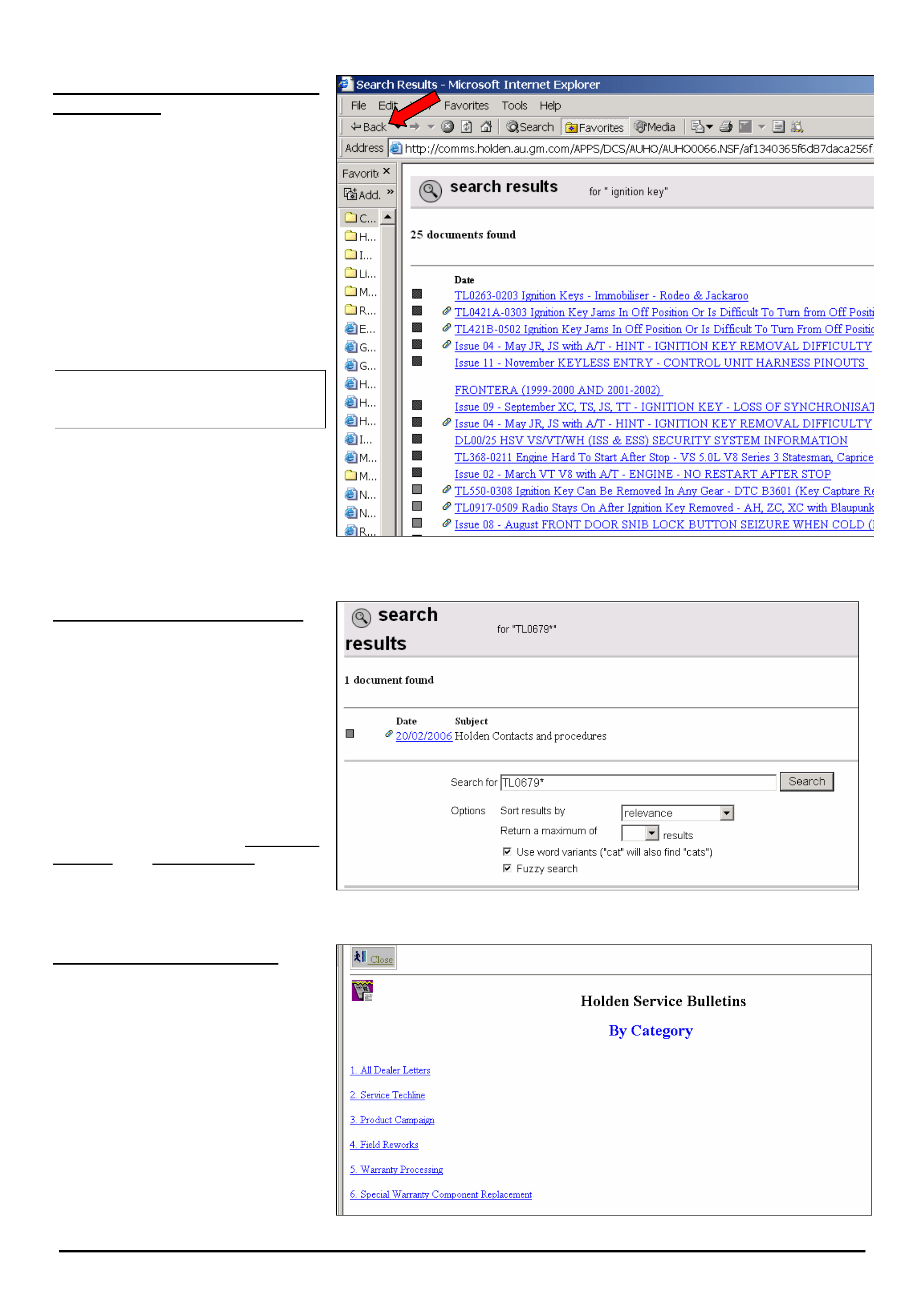
The search result is 2 documents as
shown in Figure 12.
Click on the hot-key section (in blue)
to view the techlines.
Figure 12.
HOLDEN SERVICE TECHLINES________________________________________________________________________________APRIL, 2006
14
Holden Techlines are written to inform technicians of conditions that may occur on some vehicles, and to provide information that could assist in the
proper service fix of a vehicle. If a condition is described, do not assume the service fix applies to a vehicle or that the vehicle will have that condition.
Notes on choosing “Keywords”
for searching
If we had only entered “ignition key”
without any model descriptor, this
would have located 25 items as shown
in Figure 13.
If we had only entered “ignition”, the
search would have located 86 items.
This demonstrates the importance of
selecting the right “keywords” to
search with so you don’t end up with
large numbers of items to read
through.
Rule of thumb: - The less
information in the “search window”
the more information comes back.
HINT: If at anytime you wish to go
back to the “Search” function press
the “Back” arrow in the top left side of
the toolbar. Refer red arrow in Figure
13.
Figure 13.
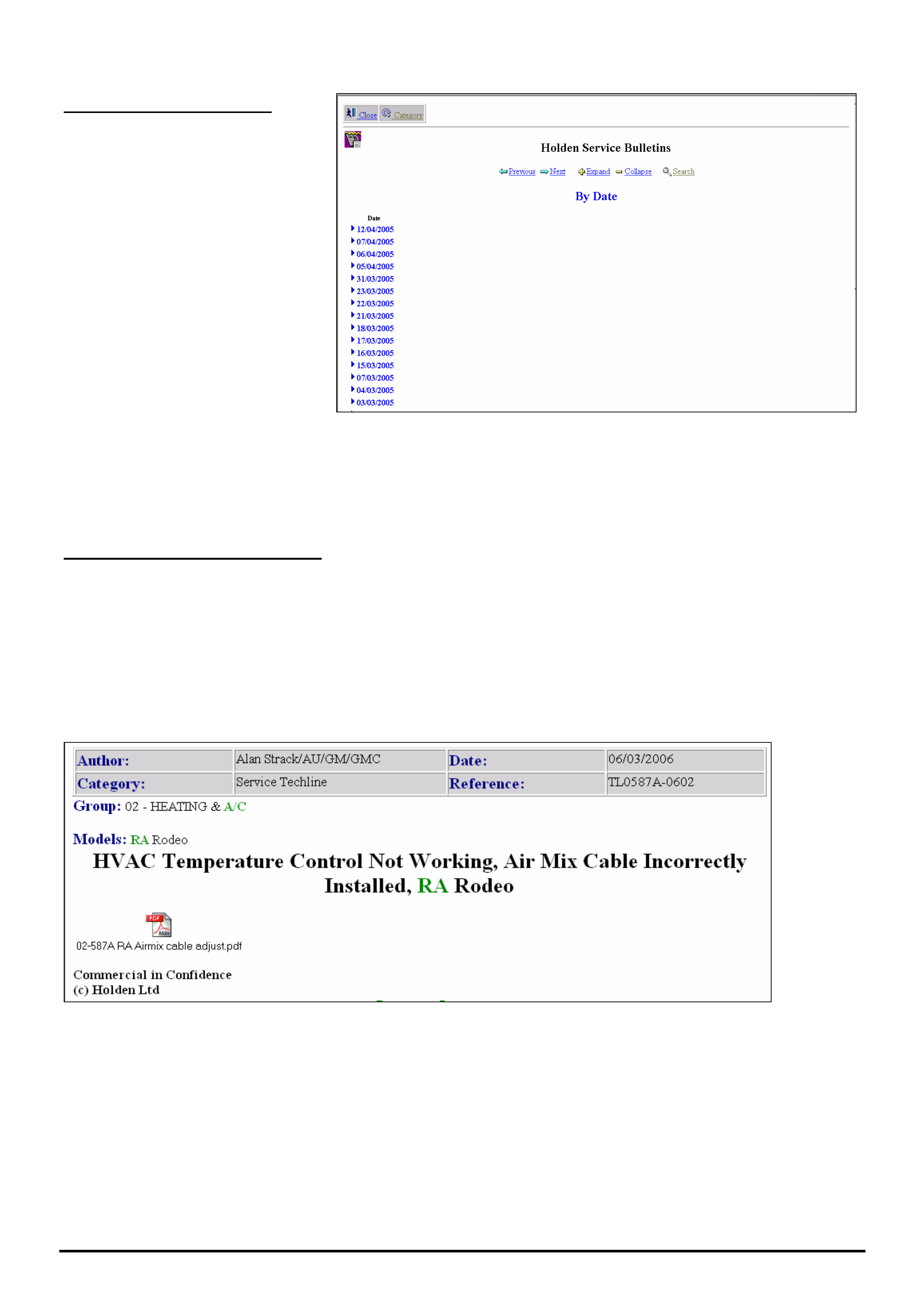
Searching by Techline Number
Use this procedure if you have an
existing techline and you want to
check to see if there is a later version
on Lionheart.
Example. - Search for the latest issue
of techline TL0679.
Type “TL0679*” in the search window
as shown in Figure 14.
Tick the last 2 boxes - “Use Word
variants” and “Fuzzy search”.
The latest version found will be
TL0679B-0602.
Figure 14
Searching Other Categories
The search procedure described
above for Service Techlines may also
be used for Dealer Letters, Campaign
Bulletin, Field rework, Warranty
Bulletin, etc. You must first select the
category you want from the Category
screen (Figure 15) before proceeding
with search.
Use the same procedure as that
described for a Service Techline.
HOLDEN SERVICE TECHLINES________________________________________________________________________________APRIL, 2006
15
Holden Techlines are written to inform technicians of conditions that may occur on some vehicles, and to provide information that could assist in the
proper service fix of a vehicle. If a condition is described, do not assume the service fix applies to a vehicle or that the vehicle will have that condition.
Figure 15.
Doing a “General” search.
To find ALL published information on
a particular subject, select “Search”
from screen shown in Figure16.
As an example, enter “Daewoo” in
the search field
This “search” will give you everything
that contains the word “Daewoo” .eg.
Dealer letters, Techlines, Recalls,
Warranty etc.
Figure 16
General Notes On Searching.
• If you perform a search and the results are not what you were looking for; to conduct another search, you will need
to hit the “← Back” arrow as shown in Figure 13. This will bring up the “active” search window. Delete the current
search keywords then enter some new keywords and press “search” again.
• The search engine cannot search any “attached” files for keywords. For example, in Figure 17, the search engine
will search through every word that actually appears on the screen as shown. It cannot search through the
attached file, viz “02-587A RA Airmix cable adjust.pdf”.
Figure 17
HOLDEN SERVICE TECHLINES________________________________________________________________________________APRIL, 2006
16
Holden Techlines are written to inform technicians of conditions that may occur on some vehicles, and to provide information that could assist in the
proper service fix of a vehicle. If a condition is described, do not assume the service fix applies to a vehicle or that the vehicle will have that condition.
• “Use Word Variants”
If you tick this box in the search panel (refer Figure 18) and type in “cat” in the “Search For” window, the search
engine will find every word that has cat in it, eg. catalytic, category, cats, etc. This is useful if you cannot remember
the exact spelling of a word or you forget the “s” when the word is plural.
Figure 18.
• Fuzzy Search
EXAMPLE 1. - Search for techlines with DTC P0335 in the Subject title.
If you accidentally type in DTCP0335 without a space between C and P, and do a Fuzzy search, the search engine
will still bring up all techlines containing “DTC P0355”.
EXAMPLE 2. - Search for techlines containing 4JX1 in the subject title.
If you type in 4JX, a fuzzy search will still find all techlines with 4JX1 in the title.
NOTE: this feature doesn’t work if you forget to enter the first letter. In this example, doing a Fuzzy search on JX1 will
not find anything.
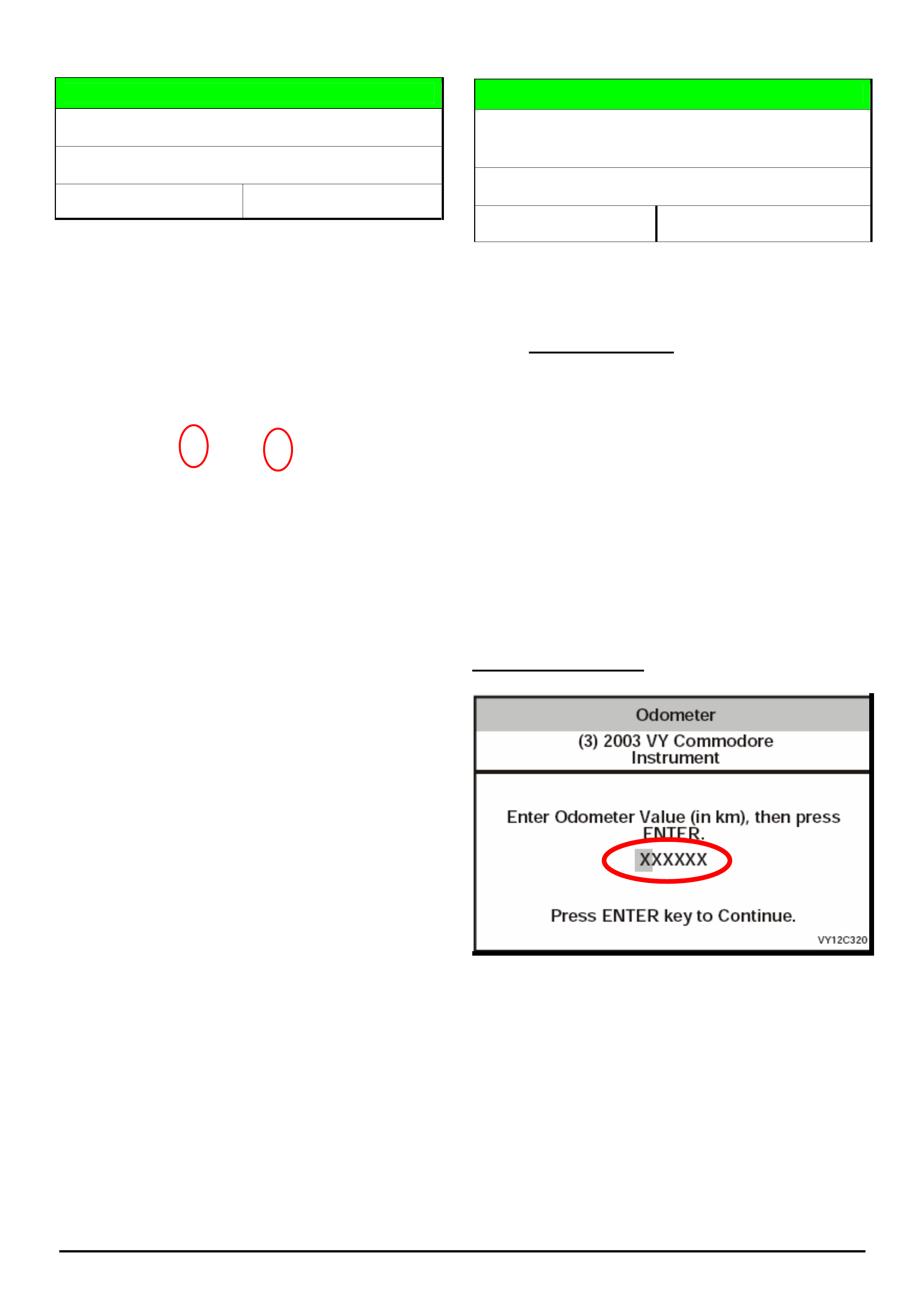
HOLDEN SERVICE TECHLINES_________________________________________________________________________________MAY, 2006
Holden Techlines are written to inform technicians of conditions that may occur on some vehicles, and to provide information that could assist in the
proper service fix of a vehicle. If a condition is described, do not assume the service fix applies to a vehicle or that the vehicle will have that condition.
DIAGNOSIS HINT
Glove Box Light Deletion
VZ (MY06 base level vehicles only)
Group 12 Ref. No. TL1121 - 0604
Customers may advise their new vehicles glove box
light is missing.
Technicians need to be aware that as of MY06, base
level vehicles have intentionally been built without a
glove box light and associated wiring.
Base level 2006 model year vehicles can be identified
by the “K” and the “6” (highlighted) in the VIN as per
the following example:
6G1ZK32B26L544522
Base model = K, Model Year 2006 = 6
Don’t try to fit the glove box light because the vehicle
has no wiring to support it.
SERVICE HINT
Programming New Instrument Clusters
(Programming Odometer Value)
All with programmable instruments
Group 12 Ref. No. TL1112-0604
This is a reminder to all technicians when programming
new instrument clusters, to confirm the odometer value
is correctly entered before programming.
IT IS NOT POSSIBLE TO CORRECT THE
VALUE ONCE PROGRAMMED.
All 6 digits have to be entered correctly as shown in the
following examples.
Example 1. - value to be entered is 15,000 km’s.
Enter as 015000.
Example 2. – if the value to be entered is 8100 km’s.
Enter as 008100
Example Tech 2 screen
All 6 Digits
Must be
used
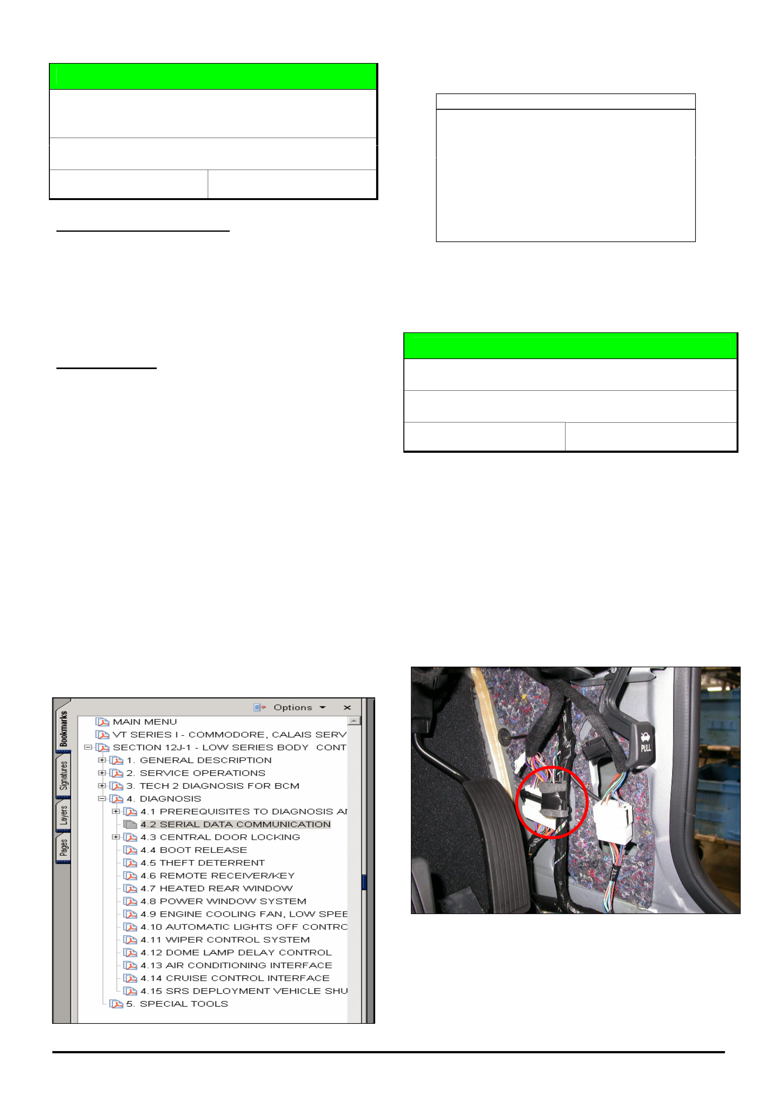
HOLDEN SERVICE TECHLINES_________________________________________________________________________________MAY, 2006
Holden Techlines are written to inform technicians of conditions that may occur on some vehicles, and to provide information that could assist in the
proper service fix of a vehicle. If a condition is described, do not assume the service fix applies to a vehicle or that the vehicle will have that condition.
DIAGNOSIS HINT
Instrument Cluster Telltales Illuminated And
No Communication With Tech 2
VT, VX, VY, V2, VU, WH, WK
Group 12 Ref. No. TL1124 - 0604
PROBLEM DESCRIPTION
If presented with a vehicle where the instrument cluster
telltales are illuminated and Tech 2 will not
communicate with any module on the serial data
network. Usually the engine will start and run.
This condition is caused by a loss of communication on
the serial data network.
Diagnosis Hint
If the engine runs, then the problem is not between
the PCM/PIM and BCM which is the primary serial data
line but rather on the secondary serial data line from
the BCM to the other modules, i.e., ECC/OCC, Radio,
ABS, PSA, SDM, Instruments, Telematics, AIM, and
Memory Seat Module. (N.B. not all vehicles will have
all these modules fitted).
If the engine does not run, then there may be an
issue relating to the primary serial data circuit between
the PCM/PIM and BCM or one of these modules.
NOTE. There is a specific diagnostic chart in
Passenger Vehicle SIP to assist technicans in
diagnosing serial data concerns. Please ensure that
this is followed prior to contacting TAS. This chart can
be found by selecting the vehicle type, then selecting
electrical system, 12J Body control module, diagnosis
and then serial data communication. An example of
where this chart is located for a VT is shown as
follows.
Acronyms Used In Techline TL1124-0604
ECC - Electronic climate control
OCC - Occupant climate control
ABS - Antilock brake system
PSA - Premium sound amplifier
SDM - Sensing diagnostic module
AIM - Audio interface module
PCM - Powertrain control module
BCM - Body control module
PIM - Powertrain interface module
SIP - Service information package
TAS - Technical assistance service
DIAGNOSIS HINT
Additional Electric Antenna Fuse
VZ (with Lux or High Series BCM), WL
Group 12 Ref. No. TL1116 - 0604
Technicians need to be aware when diagnosing an
inoperative electric antenna which has no power at the
antenna connector, that an additional 5 amp in-line
fuse was added to the above vehicle variants in
production from 30/03/06.
This additional fuse was added to protect the BCM in
the event of overload caused by damage to the electric
antenna.
Figure 1 shows the location of the additional fuse in the
drivers kick panel (next to the accelerator pedal).
Figure 1

HOLDEN SERVICE TECHLINES_________________________________________________________________________________MAY, 2006
Holden Techlines are written to inform technicians of conditions that may occur on some vehicles, and to provide information that could assist in the
proper service fix of a vehicle. If a condition is described, do not assume the service fix applies to a vehicle or that the vehicle will have that condition.
DIAGNOSIS HINT
Power Windows “Auto Drop” Function
Inoperative
XC Tigra
Group 12 Ref. No. TL1123 - 0604
When opening the doors or the roof on an XC Tigra,
the driver and/or passenger window should drop down
to create clearance so the door or roof can be opened
easily. This function is also linked to the auto-down
function of the power windows.
PROBLEM DESCRIPTION
If you are presented with a vehicle where the windows
do not drop when the roof or door is opened, and the
window auto-down function does not work, then the
electro-hydraulic roof control unit may be programmed
with “assembly mode” enabled.
This condition may occur when:
a vehicle is new,
a window regulator or hard-top control module is
replaced
the battery is disconnected.
CORRECTION
To disable “assembly mode” the control unit will need
to be reprogrammed as follows.
Programming is done with Tech 2 by selecting body,
electro-hydraulic hardtop, programming and then either
“replace driver’s window lifter” or “replace passenger’s
window lifter” as required.
Follow the Tech 2 prompts and answer the questions
accordingly.
• If “assembly mode” is enabled, then disable it by
following instructions on Tech 2 and then retest the
window operation.
• If “assembly mode” is disabled, follow normal
diagnostic processes in TIS 2000 to determine the
cause of the concern.
SERVICE FIX
Unable to Electrically Lock Or Unlock
Individual Doors
VY, WK, V2, VZ, WL
Group 12 Ref. No. TL0982 - 0604
CONDITION
Random failures of front or rear door lock actuators
causing individual doors not to electrically unlock or
lock.
CORRECTION – Service
Perform standard diagnosis using PV SIP.
If diagnosis identifies the door actuator as being faulty
replace the complete lock and actuator assembly
(parts listed below).
NOTE: When repairing vehicles during the
warranty period, replace the lock and actuator
assembly. Do not replace the actuator only.
Replacement of the lock and actuator assembly is
overall more cost effective than replacing the actuator
on its own, when comparing the labour time and cost
of parts for each situation.
PARTS INFORMATION
Part No.: Description
92187613 RHR Lock & Actuator Assembly
92187612 LHR Lock & Actuator Assembly
92187611 RHF Lock & Actuator Assembly
92187610 LHF Lock & Actuator Assembly
WARRANTY CLAIM INFORMATION
Part No.: Description
C622000 Lock Asm. RH Front Door - Replace
C623000 Lock Asm. LH Front Door - Replace
C642000 Lock Asm. RH Rear Door - Replace
C641000 Lock Asm. LH Rear Door - Replace

HOLDEN SERVICE TECHLINES_________________________________________________________________________________MAY, 2006
Holden Techlines are written to inform technicians of conditions that may occur on some vehicles, and to provide information that could assist in the
proper service fix of a vehicle. If a condition is described, do not assume the service fix applies to a vehicle or that the vehicle will have that condition.
SERVICE FIX
Sluggish On Takeoff and/or Transmission
Thumps After Takeoff
VZ, WL, Gen 3 A/T only
Group 7B Ref. No. TL1080 - 0604
CONDITION
Customers may complain that intermittently their car is
sluggish on take off, feeling like it may not be in 1st
gear. The transmission may also “thump” as it
downshifts from 2nd to 1st gear
This fault is very intermittent and may not easily be
reproduced by the dealer.
CAUSE
It is caused by erratic transmission output shaft speed
signal to the PCM at low speed, causing the vehicle to
initially take off in 2nd gear.
A revised calibration is available via TIS 2000 Version
70.0.
CORRECTION – Service
On any vehicle with the above symptoms, the
following 3 steps must be performed.
1. Re-program the ECU or PCM (engine or
powertrain control module) as per the standard SPS
(Service Programming System) process using Tech 2
and TIS 2000 version 70 or later.
NOTE: For detailed instruction on this process refer
to Holden Lionheart portal - Service Techlines\ TIS
2000\ Programming Procedures\ “Engine ECU/PCM
SPS”.
2. Re-program the Instrument cluster as per the
standard SPS (Service Programming System) process
using Tech 2 and TIS 2000 version 65 or later.
NOTE: For detailed instruction on this process refer
to Holden Lionheart portal - Service Techlines\ TIS
2000\Programming Procedures\ “Instrument Cluster
SPS”.
3. Re-program the Fuel Gauge Calibration in the
instrument cluster using Tech 2 software version
14.502 or later from TIS 2000 version 65 or later.
NOTE: For detailed instruction on this process refer
to Holden Lionheart portal - Service Techlines\ TIS
2000\ Programming Procedures\ “Instrument Cluster
Fuel Gauge calibration”.
CAUTION:
Software downloaded from TIS 2000 CD 65 or later is
not compatible with old instrument cluster software,
old engine ECU / PCM software or old fuel gauge
calibration from earlier releases of TIS 2000.
Therefore these three files must be used as a set
whenever programming an engine control module,
instrument cluster or fuel gauge calibration.
WARRANTY CLAIM INFORMATION
Description Reprogram PCM, Instrument
cluster Fuel Gauge
Labour Op. No. K000318
Time V8 - 0.4 hrs
Failure Code K0047 Flat spot or hesitates
NOTE: Labour operation number and time covers
instrument cluster, ECU / PCM and fuel gauge re-
programming.
DIAGNOSIS HINT
Engine Won’t Start After Vehicle Has
Experienced A Flat Battery
DAEWOO Matiz
Group 6C & 12 Ref. No. TL1125-0604
CONDITION
Vehicle is presented with condition where engine will
crank and not start. DTC P1602 may be logged in
ECU. Problem usually happens after vehicle has
experienced a flat battery due to ignition or lights left
on, etc.
POTENTIAL CAUSE
It is possible for the vehicle Immobilizer system to
“lose” the key coding if the battery voltage goes low.
SUGGESTED CORRECTION
• Ensure the vehicle battery is in good condition and
fully charged.
• Ensure all the vehicle’s keys are available prior to
performing the key coding and neutral conversion
procedure using either Tech 2 or Scan 100.
• If this fails to get the car started, then carry out
normal immobilizer diagnosis as per Daewoo SIP.

HOLDEN SERVICE TECHLINES_________________________________________________________________________________MAY, 2006
Holden Techlines are written to inform technicians of conditions that may occur on some vehicles, and to provide information that could assist in the
proper service fix of a vehicle. If a condition is described, do not assume the service fix applies to a vehicle or that the vehicle will have that condition.
DIAGNOSIS HINT
Discolouration And Paint Swelling Observed
At Pre Delivery
AH Astra
Group 1 Ref. No. TL1107 - 0604
Condition:
There have been isolated reports of paint
discolouration on horizontal surfaces on AH Astra at
pre delivery.
The light metallic colours seem to be the most
commonly affected.
Cause:
When applying the wrapguard (used for paint
protection when shipping), it is impossible to avoid
folds and bubbles. Moisture can be trapped in these
folds and bubbles and, over the shipping time, can
cause paint swellings and discolourations.
Correction:
After removal of the wrapguard at Port Of Entry, these
swellings and discolourations will normally disappear
after the car has been exposed to the sun for a couple
of days.
If the swellings and discolourations are still evident at
Predelivery Inspection, they may be treated with the
application of heat.
For small areas, a heat gun may be used to gently
heat the area until the condition is reversed. DO NOT
OVERHEAT the surface.
For larger areas, and closer control of the application
of heat, a baking oven may be used.
NOTE: The temperatures and times typically required
to achieve reversal of the condition are described in
the material specifications of the shipping wrapguard
as follows.
2.0 hr ± 5 min at 60°C ± 3°C or if this fails,
0.5 hr ± 5 min at 80°C ± 3°C
If the swellings and discolourations are still evident
after heating, then you should seek Zone approval for
a paint repair.

HOLDEN SERVICE TECHLINES_________________________________________________________________________________MAY, 2006
Holden Techlines are written to inform technicians of conditions that may occur on some vehicles, and to provide information that could assist in the
proper service fix of a vehicle. If a condition is described, do not assume the service fix applies to a vehicle or that the vehicle will have that condition.
DIAGNOSIS HINT
Low Traction Event Occurs Unnecessarily
During Take Off
VZ, WL, without ESP
Group 5 Ref. No. TL1042A-0604
This Techline supercedes the previous one in Issue 11,
Dec, 2005. It is UPDATED to include auto transmission
vehicles.
CONDITION
During take off, a low traction event occurs
unnecessarily. The low traction indicator is illuminated.
POSSIBLE CAUSE
This condition could be due to an insufficient air gap
between rear wheel speed sensors and tone wheel.
SUGGESTED CORRECTION
Check air gap measurement and adjust if required.
1. Check air gap of both of the rear wheel speed
sensors.
2. Air gap needs to be 1.5mm.
3. If less than 1.5mm, use shim part number
90278359 to achieve the correct air gap spacing.
PARTS INFORMATION
Part No.: Description Qty:
90278359 Shim 1
DIAGNOSIS HINT
ABS/ESP Warning Light Illuminates
Unnecessarily, DTC C0245 Logged.
VZ, WL, with ESP
Group 5 Ref. No. TL1127-0604
CONDITION
When shifting between gears whilst stationary e.g. -
Park to Drive or Drive to Park, the ABS warning light
illuminates and DTC C0245 is logged.
POSSIBLE CAUSE
This condition could be due to an insufficient air gap
between rear wheel speed sensors and tone wheel.
SUGGESTED CORRECTION
Check air gap measurement and adjust if required.
Check air gap of both of the rear wheel speed
sensors.
Air gap needs to be 1.5mm.
If less than 1.5mm, use shim part number
90278359 to achieve the correct air gap spacing.
DO NOT replace the ABS module for this condition.
PARTS INFORMATION
Part No.: Description Qty:
90278359 Shim 1
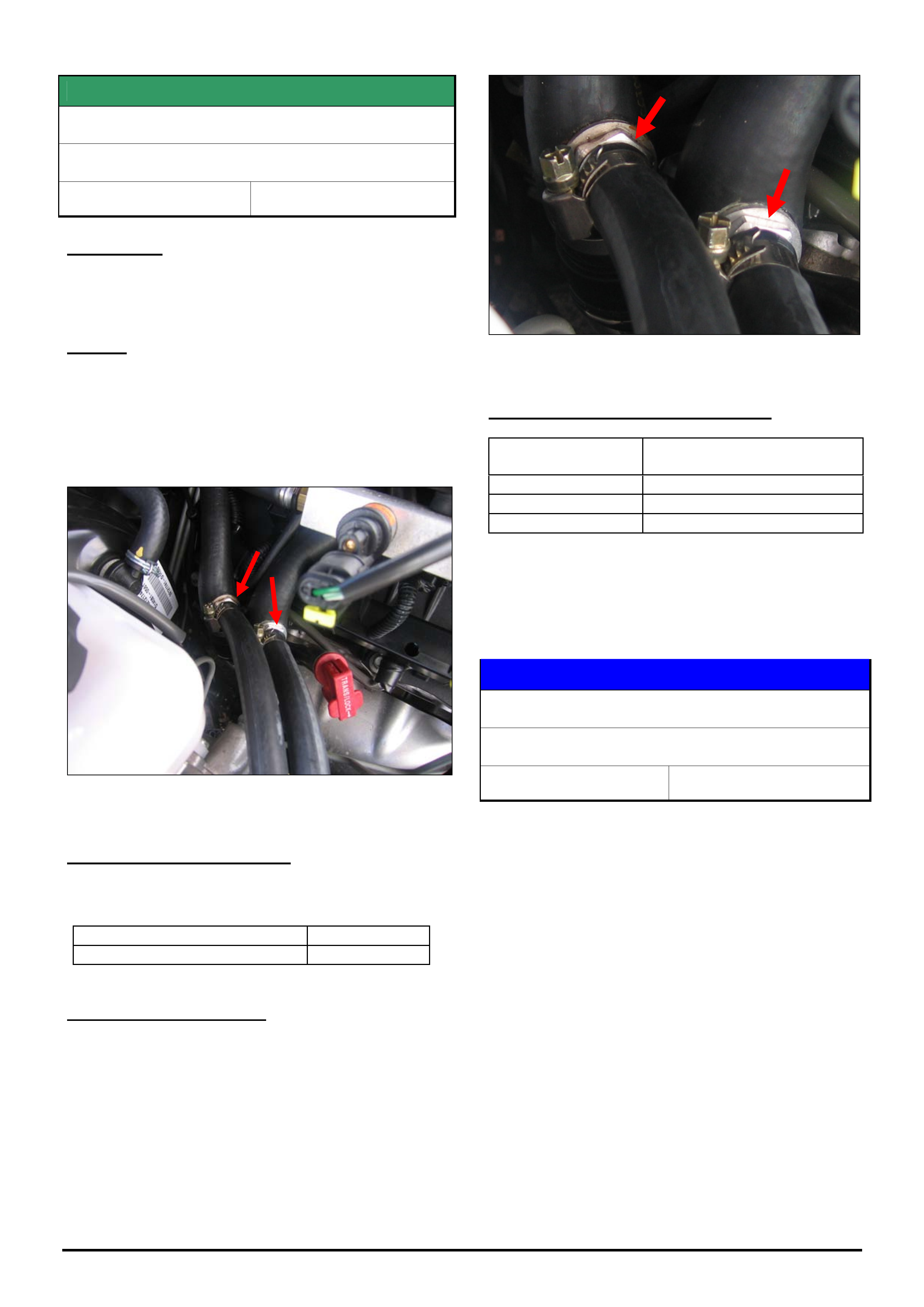
HOLDEN SERVICE TECHLINES_________________________________________________________________________________MAY, 2006
Holden Techlines are written to inform technicians of conditions that may occur on some vehicles, and to provide information that could assist in the
proper service fix of a vehicle. If a condition is described, do not assume the service fix applies to a vehicle or that the vehicle will have that condition.
SERVICE FIX
LPG Heater Hose Connection Leak
VZ LPG
Group 6M Ref. No. TL1095 - 0604
CONDITION
A coolant leak at the heater hose connections for the
LPG converter.
CAUSE
The fittings that are installed into the existing heater
hoses to provide coolant to the LPG converter,
consists of an alloy spigot and a nut to retain the fitting
into the heater hose. It is the nut component of the
fitting that is loose and causing the leak. Refer Figures
1 and 2.
Figure 1
CORRECTION – Production
Loctite was applied to the heater hose fitting nut on
vehicles from
ISOVIN: Built Date:
- 07/03/06
CORRECTION – Service
Summary: After verifying that vehicle has condition as
described above, apply loctite to the nut on the fitting
and re-tension.
Procedure
1. Loosen nut from fitting to expose thread.
2. Apply a spot of loctite 262 or equivalent to the
thread.
3. Reinstall nut and torque to 4 Nm.
Figure 2.
WARRANTY CLAIM INFORMATION
Description Rectify leak at LPG heater
hose connection. (2 places)
Labour Op. No. J000803
Time 0.4 hr
Failure Code J0042 leaks
SERVICE PROCEDURE
HFV6 Timing Cover Removal
VZ, WL
Group 6A Ref. No. TL1110 - 0604
When performing any work on a HFV6 engine that
requires removal of the front timing cover, technicians
must ensure that they are following the procedure
outlined in SIP.
Particular attention needs to be paid to draining the
coolant prior to removal of the timing cover.
Failure to do this may result in coolant entering the oil
pan and contaminating the oil. This may lead to
incorrect diagnosis of a perceived engine problem (e.g.
head gasket) or damage to the engine.
Refer to Passenger Vehicle SIP section 6A1 for the
correct procedure.
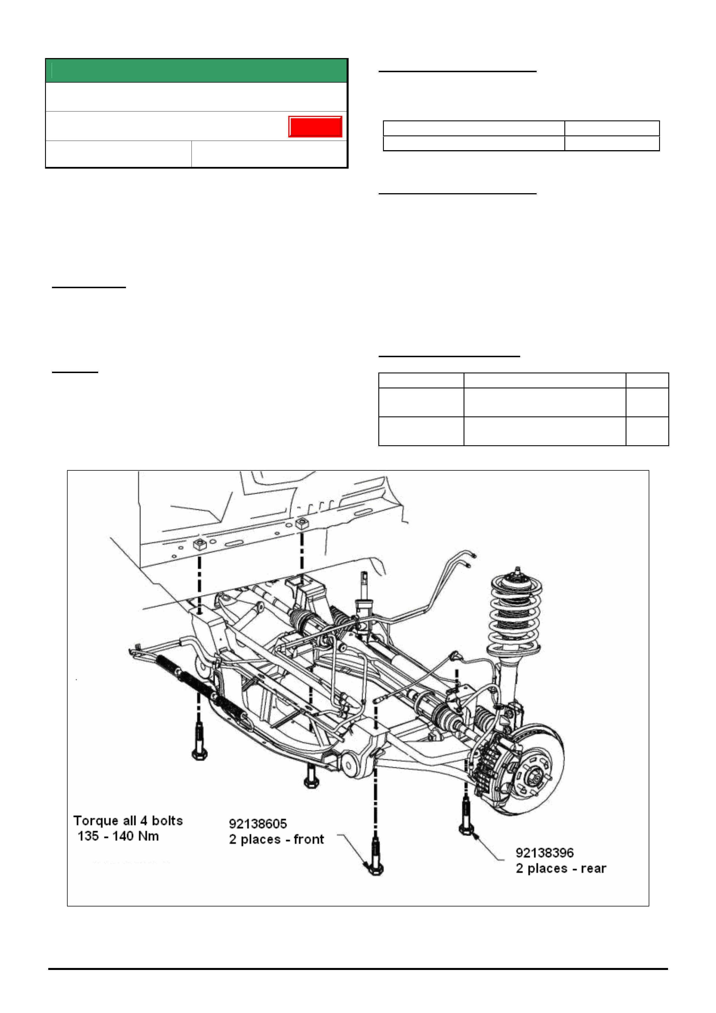
HOLDEN SERVICE TECHLINES_________________________________________________________________________________MAY, 2006
Holden Techlines are written to inform technicians of conditions that may occur on some vehicles, and to provide information that could assist in the
proper service fix of a vehicle. If a condition is described, do not assume the service fix applies to a vehicle or that the vehicle will have that condition.
SERVICE FIX
Front Suspension Clunk (Front Subframe)
VT, VU, VX, VY, V2, VZ, WH, WK, WL
Group 3 Ref. No. TL0718B-0604
This Techline supercedes the previous one in Issue 2, Mar,
2005. It is revised by including all V & W models as shown. It
also applies to 2WD / AWD and all model variants
Also refer to Techline TL0638-0403 published in Issue 3, 2004
which gives another possible cause for front suspension
clunk
CONDITION
Loud metallic clunk noise from front suspension
usually heard when driving over pot holes or braking
over speedhumps .
CAUSE
One possible cause for this condition is fore-aft
movement of the front subframe relative to the body
due to insufficient clamp load at the attaching points.
CORRECTION – Production
Torque on all front cross member bolts increased to
135 – 140 Nm from:
ISOVIN: Built Date:
**********L540735 28/11/2005
CORRECTION – Service
On any vehicle with the symptoms as described
ensure that all 4 subframe mounting bolts are
tightened to 135 -140 Nm.
NOTE: As these bolts are being tightened only and
not removed, they do not need replacing.
If they are removed for any reason then they should be
replaced as per the standard practice for micro
encapsulated fasteners.
PARTS INFORMATION
Part No.: Description: Qty
92138605 Bolt Front suspension
frame - front
2
92138396 Bolt Front suspension
frame - rear
2
Figure shows AWD front end.
Update
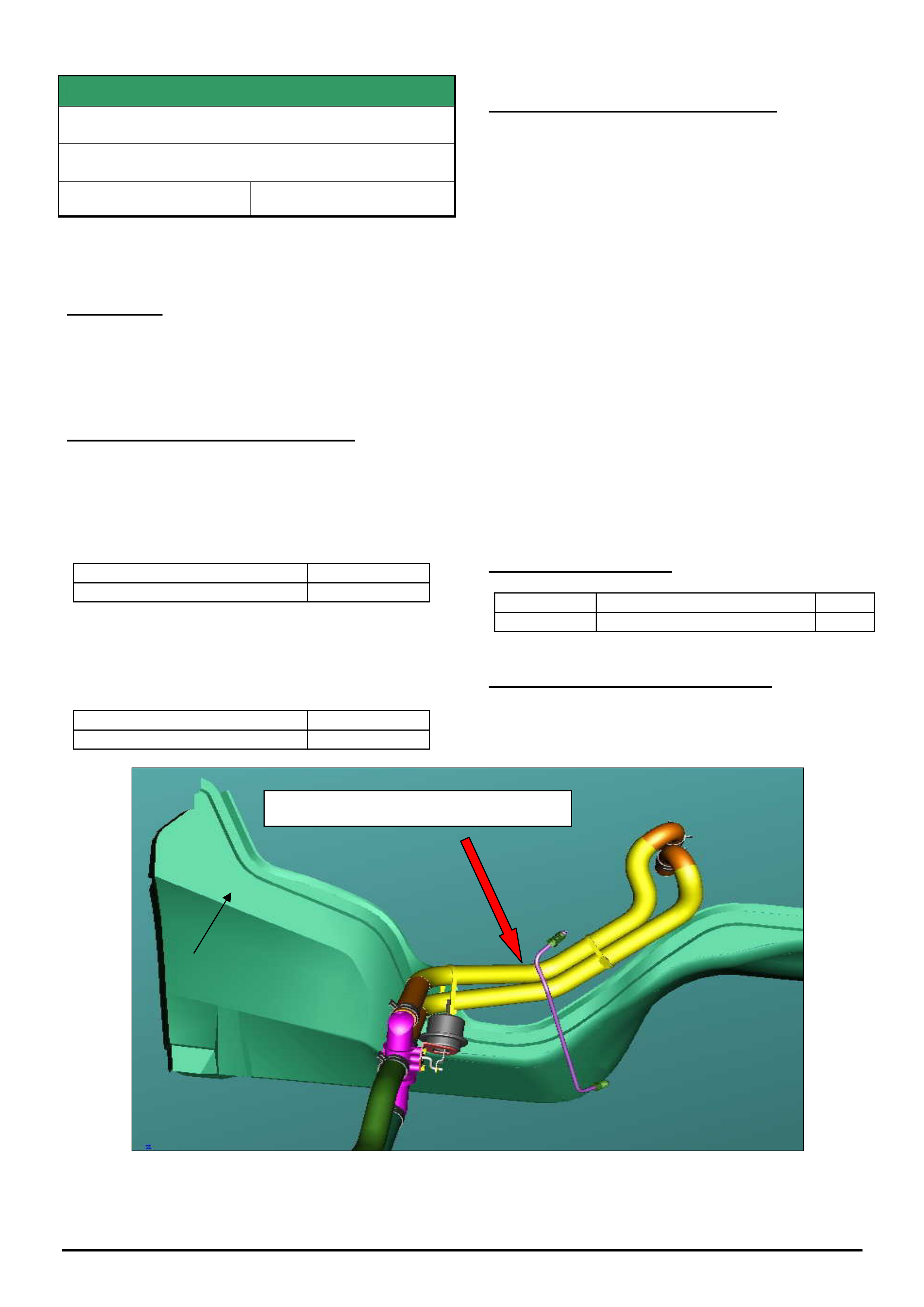
HOLDEN SERVICE TECHLINES_________________________________________________________________________________JUNE, 2006
5
Holden Techlines are written to inform technicians of conditions that may occur on some vehicles, and to provide information that could assist in the
proper service fix of a vehicle. If a condition is described, do not assume the service fix applies to a vehicle or that the vehicle will have that condition.
SERVICE FIX
Heater Hose Rubs On Rear Of Cylinder Head
VY, VZ, WK, WL, V8 Engine
Group 2 Ref. No. TL0867A - 0605
This Techline supercedes the previous one (TL0867-0510)
in Issue 10, Nov. 2005. It is UPDATED by including A/T
models and by revising the method of correction.
CONDITION
There have been isolated cases where the heater hose
has been damaged due to contact with the rear of the
right hand side cylinder head.
CORRECTION – Vehicle Production
Production rectification happened in two stages.
The 1st stage was to revise the shape of the clutch pipe
on M/T vehicles to provide greater clearance between
the heater hoses and cylinder head.
Revised clutch pipe was fitted to M/T vehicles from:
ISOVIN: Built Date:
**********L484030 01/08/05
The 2nd stage was to add a butyl patch to the rear of
RH cylinder head to protect the heater hoses from
sharp edges.
Butyl patches were added to all V8 models from:
ISOVIN: Built Date:
**********L816323 12/4/06
CORRECTION – Vehicles in Service
On any vehicle where the heater hose is being
replaced, proceed as follows:
Manual Transmission Vehicles.
1. On vehicles built before 1/8/2005, route the new
hose between the clutch pipe and the dash panel as
shown in Figure 1.
On vehicles built after 1/8/2005 (fitted with revised
shape clutch pipe) route the new hose in front of the
clutch pipe.
2. If not already fitted, apply butyl patch 92018621 to
the rear of the cylinder head as shown in Figure 2.
Ensure that the head surface is thoroughly clean
before applying patch.
Automatic Transmission Vehicles.
If not already fitted, apply butyl patch 92018621 to
the rear of the cylinder head as shown in Figure 2.
Ensure that the head surface is thoroughly clean
before applying
PARTS INFORMATION
Part No.: Description Qty:
92018621 Butyl sheet 1
WARRANTY CLAIM INFORMATION
Use Labour Times information in Warranty Information
section of current PV SIP CD
Figure 1. Heater hose routing on M/T vehicles built prior to L484030 (built 1/8/2005)
Route hoses behind clutch pipe
Dash panel
glue track
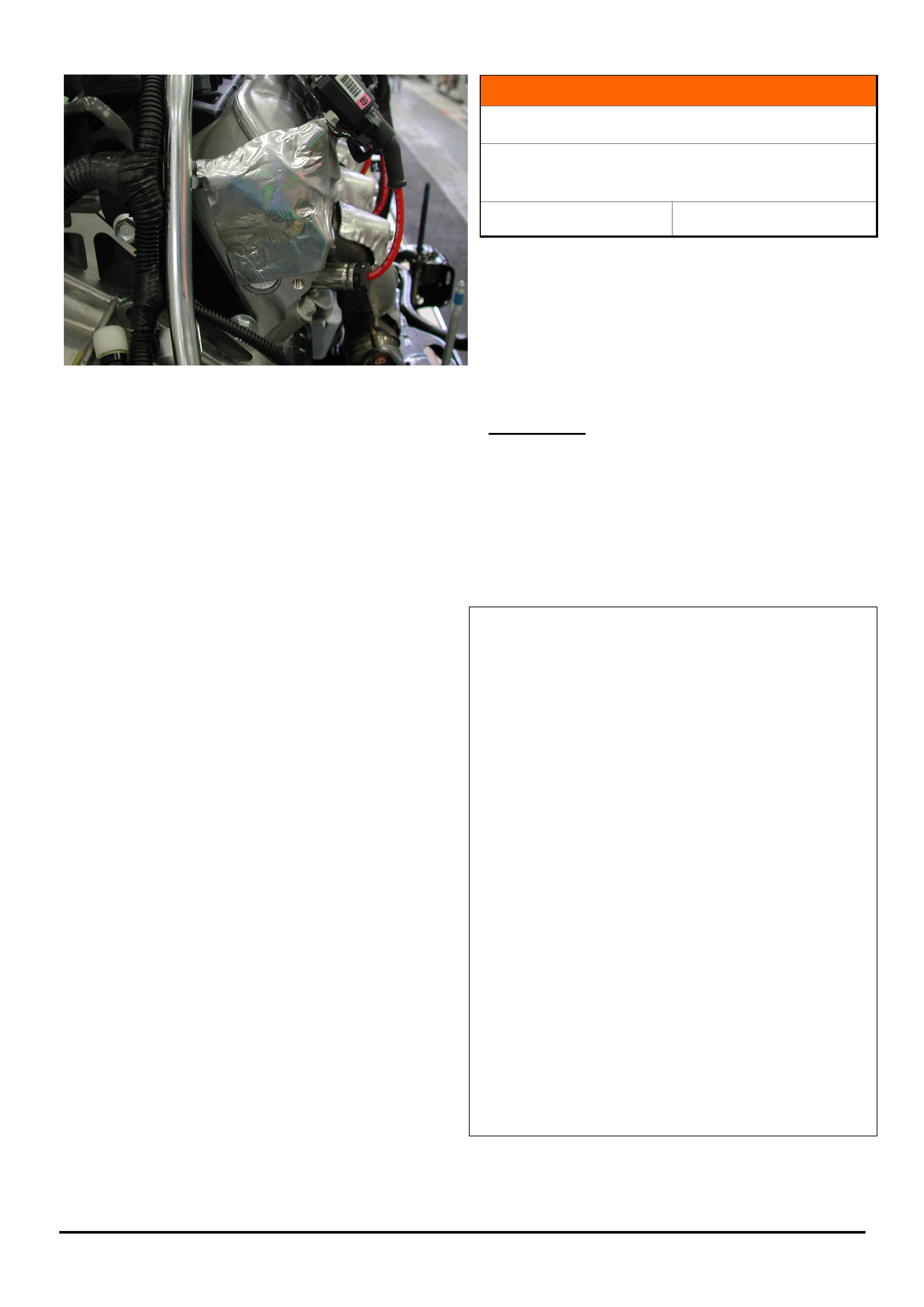
HOLDEN SERVICE TECHLINES_________________________________________________________________________________JUNE, 2006
6
Holden Techlines are written to inform technicians of conditions that may occur on some vehicles, and to provide information that could assist in the
proper service fix of a vehicle. If a condition is described, do not assume the service fix applies to a vehicle or that the vehicle will have that condition.
Figure 2. Butyl patch (92018621) applied to rear of
RH cylinder head (Auto. Trans. engine shown)
INFORMATION
Oxygen Sensor Software Improvements
VZ, WL, with 190 kW HFV6
VZ Cross 6 AWD with 175 kW HFV6
Group 6C Ref. No. TL1133 - 0605
Revised software to improve the durability of Oxygen
sensors in the above models was introduced from TIS
2000 version 69.0.
Therefore, whenever replacing the O2 sensors on any
models as listed above, the engine calibration should
be updated with the latest software from TIS 2000
version 69.0 and later.
IMPORTANT:
Software downloaded from TIS 2000 CD 65 or later is
not compatible with old instrument cluster software, old
engine ECU/PCM software or old fuel gauge calibration
from earlier releases of TIS 2000.
Therefore these three files must be used as a set
whenever programming an engine control module,
instrument cluster or fuel gauge calibration.
1. Re-program the ECU or PCM (engine or
powertrain control module) as per the standard SPS
(Service Programming System) process using Tech 2
and TIS 2000 version 69 or later.
NOTE: For detailed instruction on this process refer
to Holden Lionheart portal, Service Techlines\
TIS 2000 \ Programming Procedures \ “Engine ECU
/ PCM SPS”.
2. Re-program the Instrument cluster as per the
standard SPS (Service Programming System) process
using Tech 2 and TIS 2000 version 65 or later.
NOTE: For detailed instruction on this process refer
to Holden Lionheart portal, Service Techlines \ TIS
2000 \ Programming Procedures \ “Instrument
Cluster SPS”.
3. Re-program the Fuel Gauge Calibration in the
instrument cluster using Tech 2 software version
14.502 or later from TIS 2000 version 65 or later.
NOTE: For detailed instruction on this process refer
to Holden Lionheart portal, Service Techlines\ TIS
2000\ Programming Procedures\ “Instrument Cluster
Fuel Gauge Calibration”.
NOTE: The software revisions for improved O2 sensor
durability were introduced in vehicle production at
Model Year 2006.
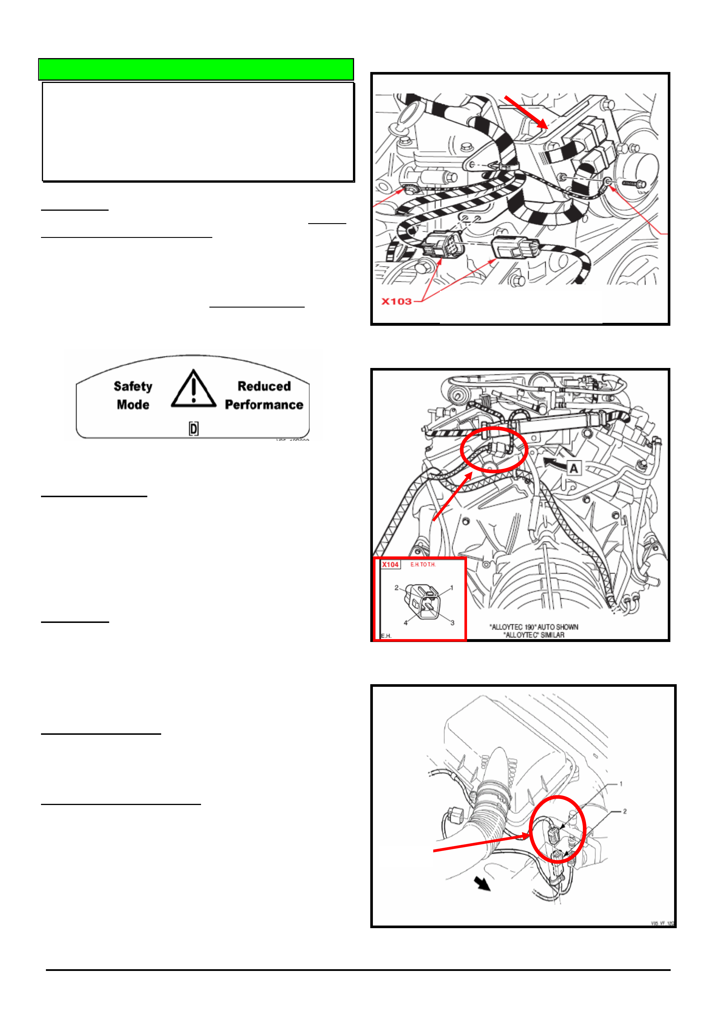
HOLDEN SERVICE TECHLINES_________________________________________________________________________________JUNE, 2006
7
Holden Techlines are written to inform technicians of conditions that may occur on some vehicles, and to provide information that could assist in the
proper service fix of a vehicle. If a condition is described, do not assume the service fix applies to a vehicle or that the vehicle will have that condition.
DIAGNOSIS HINT
“Safety Mode / Reduced Performance”
Displayed in Instruments MFD
VZ,WL, V6 and 6.0L V8 (L76) Auto. Trans. only
(GROUP 12) TL1109-0605
CONDITION
The customer may report seeing the warning “Safety
Mode / Reduced performance” displayed in instrument
cluster MFD (Multi Function Display). Refer figure 1.
Also, the automatic transmission may default to top gear.
(Fail safe mode)
No DTC’s are set, and Tech 2 can communicate with all
modules including the TCM (Transmission Control
Module) i.e. it passes an ‘ECU presence check’
Figure 1. Instrument Cluster MFD Message
POSSIBLE CAUSE
A possible cause of this fault is no ignition power supply
to the TCM
Note: Ignition supply voltage can be seen using Tech 2
in transmission datalist: “IGNITION VOLTAGE – 12V”
Note: Tech 2 will continue to communicate with the TCM
even without ignition power.
V6 Engine: A potential cause of this is a poor
connection or backed out terminal in either connector
X103 8 pin located near the engine ECU Refer figure 2
or connector X104, a 4 pin connector located at the rear
of the L/H cylinder head, Refer figure 3.
Ignition power supply to the TCM is via fuse 8 and then
passes through these connectors.
V8 6.0L (L76) Engine: The ignition supply to the TCM on
an L76 V8 engine passes through connector X101, a 5 pin
located near the air cleaner housing. Refer figure 4.
SUGGESTED CORRECTION
If presented with a vehicle with the condition as
described above, use Tech 2 to check the ignition supply
voltage into the TCM.
If no voltage is present, check fuse 8 (Automatic
Transmission) is ok. If this fuse is blown, check the entire
circuit to locate the reason for the failure. If the fuse is
intact, ensure proper terminal retention in the
connectors X103 & X104 V6, or X101 V8 and the
connectors are secured together properly.
If this fails to correct the problem then do standard
electrical fault diagnosis on the remainder of the circuit.
Figure 2 (V6)
Figure 3 (V6)
Figure 4 (6.0L-V8)
Front of Engine
Engine Computer
Rear of
Engine
X101
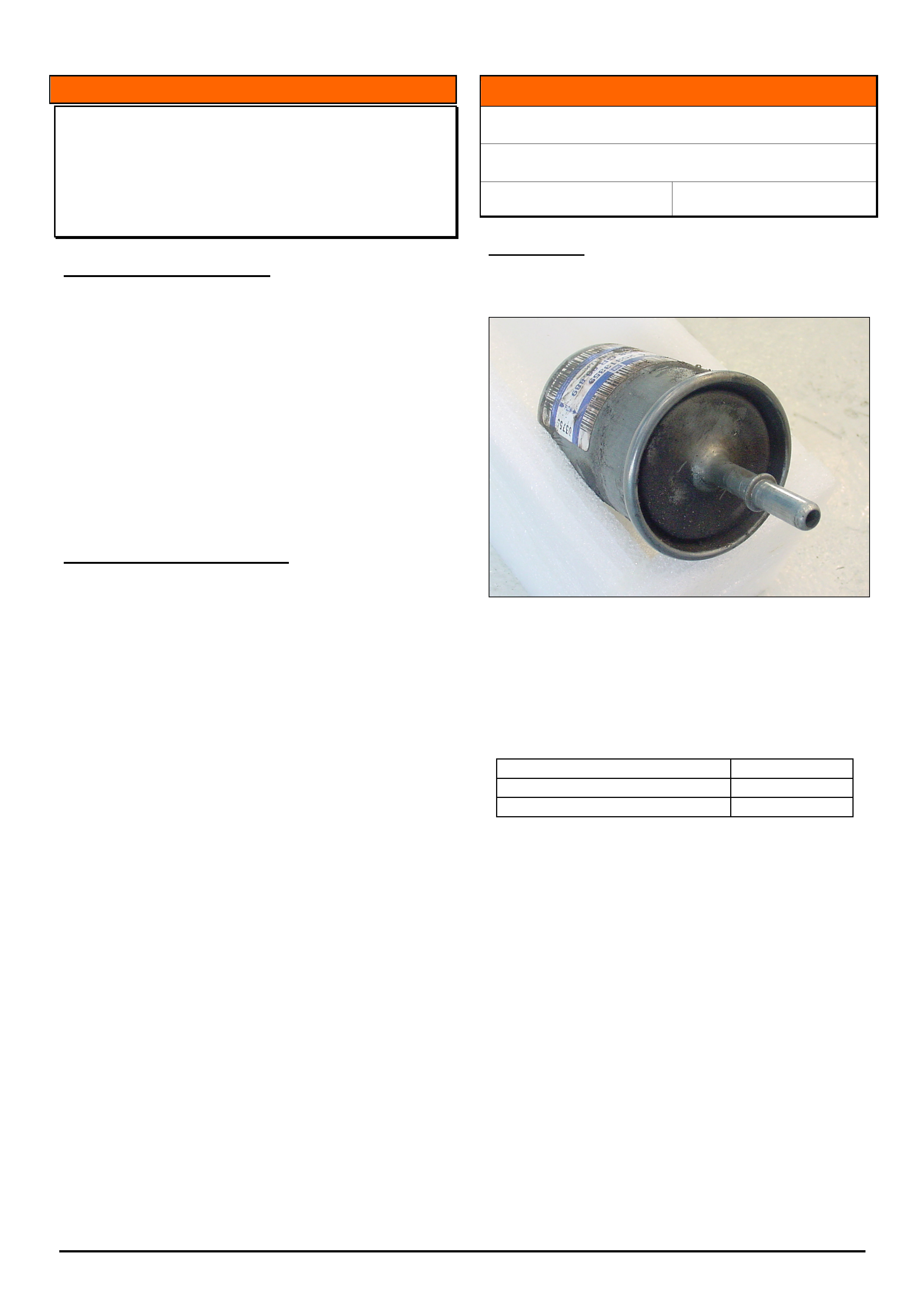
HOLDEN SERVICE TECHLINES_________________________________________________________________________________JUNE, 2006
9
Holden Techlines are written to inform technicians of conditions that may occur on some vehicles, and to provide information that could assist in the
proper service fix of a vehicle. If a condition is described, do not assume the service fix applies to a vehicle or that the vehicle will have that condition.
INFORMATION
Replacing Entertainment Head Units (Radios)
ZC, AH, XC with BLAUPUNKT CD30 or CD40
Units Fitted
(GROUP 12) TL1138-0605
PROBLEM DESCRIPTION
Many dealers contact TAS because they have replaced
Blaupunkt CD 30 or CD 40 radio head units and then
found that the unit is not working properly or there are
messages on the information display such as “display
safe” or “radio safe”.
Dealers need to be aware that these radio units are
security linked to the information display in the vehicle
and need to be reset prior to being removed from the
vehicle. The replacement radio then needs to be linked
to the display with Tech 2. The radio also needs
various parameters to be programmed in with Tech 2.
Radio Replacement procedure
Whenever removing a radio unit and replacing it
with another, the following procedure must be
adhered to.
1. Obtain vehicle security number, ie immobiliser
number (refer vehicle security card, dealer records or
Dealer Letter 42/05).
2. With Tech 2 select the following.
Infotainment system, EHU (entertainment head unit),
programming, reset ecu, and then follow the Tech 2
prompts.
3. Remove the radio.
4. Fit the new radio.
5. With Tech 2 select the following.
Infotainment system, EHU (entertainment head unit),
programming, program ecu, and then follow the Tech 2
prompts.
NOTE: Failure to reset an entertainment head unit prior
to replacement may result in the radio not being
accepted under warranty.
INFORMATION
Fuel Filter Staining
XC, TS, TT, ZC
Group 6M Ref. No. TL1128 - 0605
CONDITION
Dealers have been reporting stained appearance of the
end cap of the fuel filter as shown in photograph.
Investigations have resulted in improvements to the
fuel filter manufacturing process to eliminate the above
condition.
Fuel filters from the improved manufacturing process
have been fitted to vehicles from:
ISOVIN: Built Date:
W0L0XCF2553051901 29/04/2005
W0L0TGF485G091908 28/04/2005
Dealers are requested to only submit PIRs if the above
condition is observed on vehicles built after the above
breakpoints.
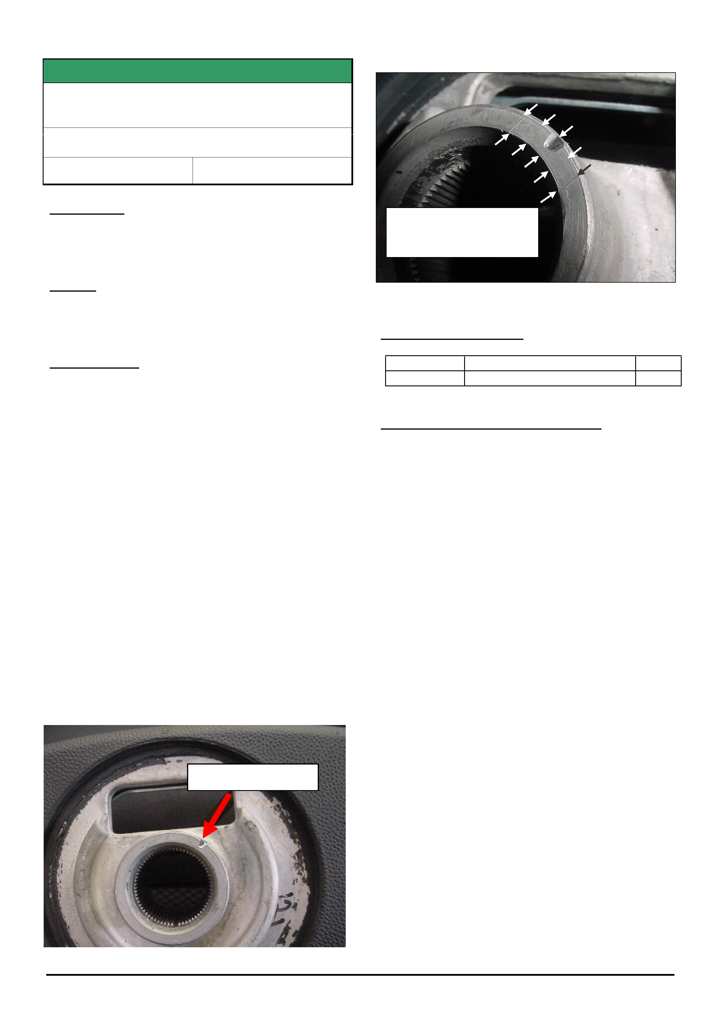
HOLDEN SERVICE TECHLINES_________________________________________________________________________________JUNE, 2006
11
Holden Techlines are written to inform technicians of conditions that may occur on some vehicles, and to provide information that could assist in the
proper service fix of a vehicle. If a condition is described, do not assume the service fix applies to a vehicle or that the vehicle will have that condition.
SERVICE FIX
Noise From Centre Of Steering Wheel When
Turning
AH Astra
Group 9 Ref. No. TL1094 - 0605
CONDITION
Chafing noise from Column Integration Module (CIM)
may occur when turning steering wheel.
CAUSE
Relative movement between centre of steering wheel
and the unlocking mechanism of the winding spring.
CORRECTION
Summary: After verifying that vehicle has condition as
described above, fit noise insulating tape as per
following procedure. Do Not replace CIM for this
condition.
1. Remove the steering wheel as per procedure in
TIS 2000. Refer Standard Service Information,
Group M "steering wheel replace”, (Document No.
00601214).
NOTE: When removing the steering wheel do not
move the position of the steering angle sensor
otherwise the sensor must be recalibrated.
2. Add a 20 mm strip of self adhesive anti-squeak
tape (cut from 92149173) to cover the indentation
in the hub on the underside of the steering wheel.
Refer figure 1. Trim tape to shape of the boss. i.e.
cut off any overhang.
NOTE: To improve the adhesion of the tape, degrease
the hub first. Ensure that you wait 45 minutes before
reinstalling the steering wheel to allow the adhesive
tape sufficient time to cure.
Figure 1. View of underside of steering wheel.
Figure 2.
PARTS INFORMATION
Part No.: Description Qty:
92149173 tape (20 cm length) 1
WARRANTY CLAIM INFORMATION
Use standard Labour Times found in the Warranty
Information section of the current PV SIP disc for
Remove and Replace Steering Wheel.
.
Use sharp blade to trim
tape to shape of hub.
(cut off overhang)
Add tape to this area
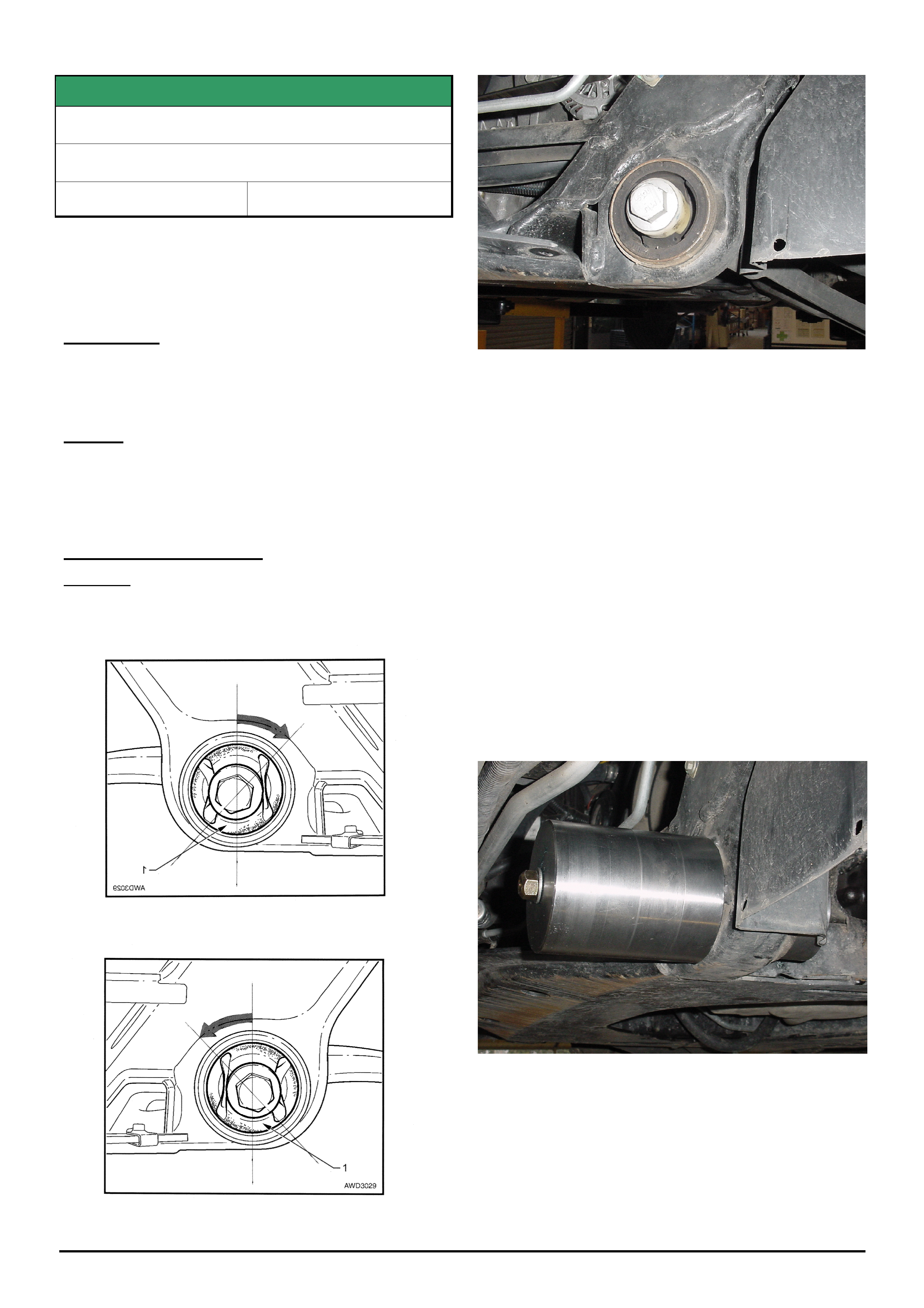
HOLDEN SERVICE TECHLINES_________________________________________________________________________________JUNE, 2006
12
Holden Techlines are written to inform technicians of conditions that may occur on some vehicles, and to provide information that could assist in the
proper service fix of a vehicle. If a condition is described, do not assume the service fix applies to a vehicle or that the vehicle will have that condition.
SERVICE FIX
Front End Suspension – Metallic Clunk Noise
AWD Adventra, X6 and X8 Crewman
Group 3 Ref. No. TL1079 - 0605
Note: Previous techlines on AWD clunk must be carried
out before attempting this procedure. Refer Techlines:
TL0638-0403 (Issue 3, 2004) and TL0718B-0604
(Issue 4, 2006).
CONDITION
A metallic clunk is heard from the front suspension
when braking over rough surfaces.
CAUSE
Excessive movement of the lower control arms which
cause impact noise to be transferred through the
bushes into the suspension cradle.
CORRECTION – Service
Summary: After verifying that vehicle has condition as
described above, remove and rotate front lower control
arm front bush by 45 degrees.
Figure 1. (Drivers side)
Figure 2. (Passenger side)
Figure 3. Shows front bush in original orientation
1. Place vehicle on hoist and remove the front
wheels.
2. Remove the steering tie rod ball joint from the
knuckle.
3. Support lower control arm with a transmission jack.
4. Remove the front and rear bush bolts from the
control arm and lower the control arm out of the
cradle, supporting it on the transmission jack.
Note: It is not necessary to remove the control
arm from the vehicle. It can rest on the
transmission jack and remain connected to the
control arm ball joint.
5. Use control arm front isolator bush removing tool
number CH-47568 (details of tool in SIP) to remove
the front bush from the cradle. Refer figure 4.
Figure 4.
6. Rotate bush 45 degrees toward the centre of the
vehicle as per figure 1 and 2.
7. Reinstall bush into the cradle using tool CH-47568.
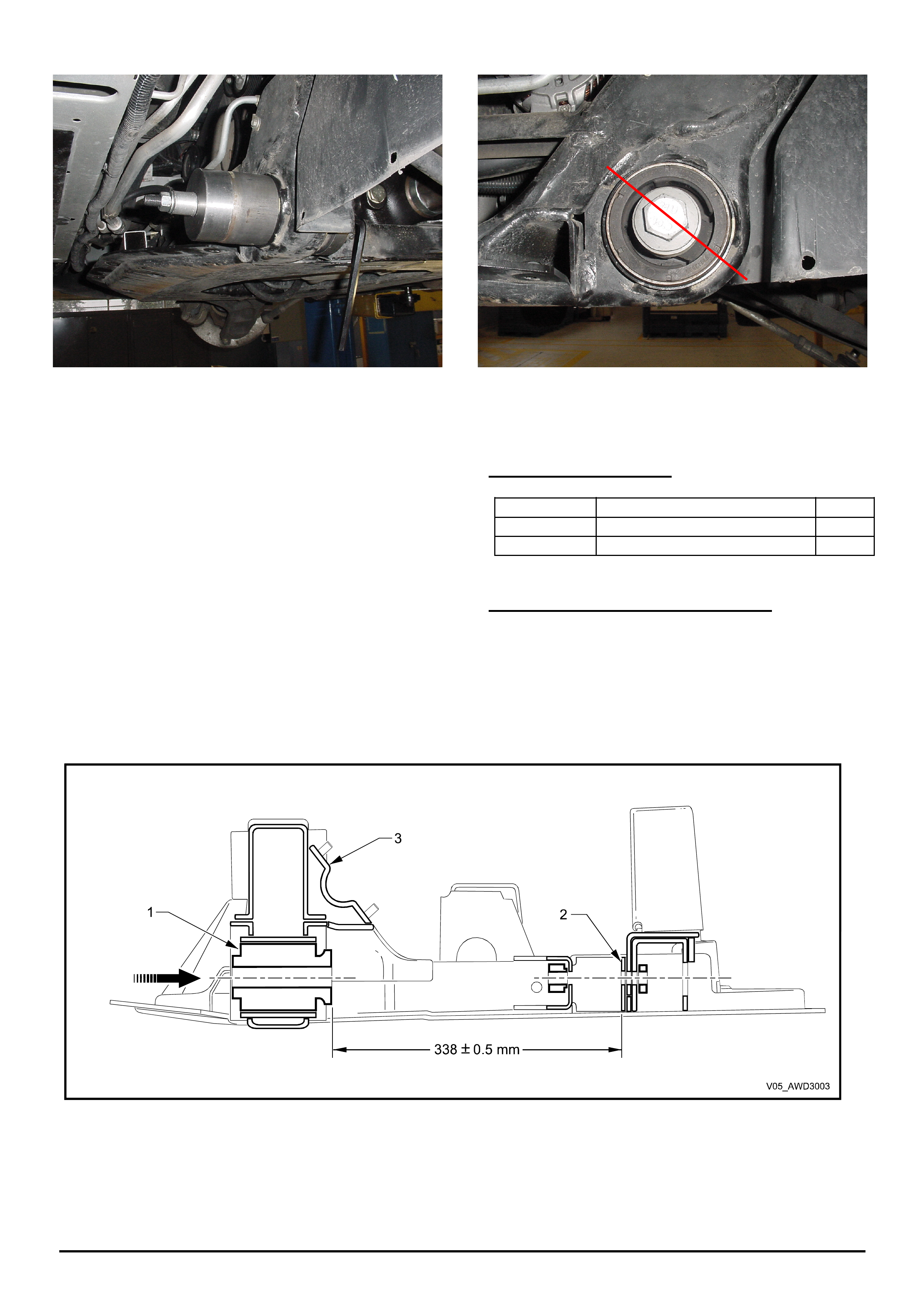
HOLDEN SERVICE TECHLINES_________________________________________________________________________________JUNE, 2006
13
Holden Techlines are written to inform technicians of conditions that may occur on some vehicles, and to provide information that could assist in the
proper service fix of a vehicle. If a condition is described, do not assume the service fix applies to a vehicle or that the vehicle will have that condition.
Figure 5.(Reinstalling bush)
8. Install bush to the dimensions 338+/-0.5mm from
the rear of the bush to the rear bush mount as
per figure 6.
9. The bush should have the voids at a 45 degree
angle from vertical as per figure 7.
10. Reinstall lower control arm ensuring new bolts
are used.
11. Reinstall steering arm to knuckle.
12. Repeat procedure on other side of vehicle.
Figure 7 Passenger side bush after rotation)
PARTS INFORMATION
Part No.: Description Qty:
92138666 Bolt-Lower control arm-Front 2
92138729 Bolt-Lower control arm-Rear 2
WARRANTY CLAIM INFORMATION
Use Labour Times information in Warranty Information
section of current PV SIP CD.
E100010 - Bush Asm Front Lower Control Arm replace
both sides.
Figure 6. The distance from the inner flange of the front isolating bush (1) to the rear land (2) for the rear
bush in the front crossmember cradle (3) is to be 338 +/- 0.5mm
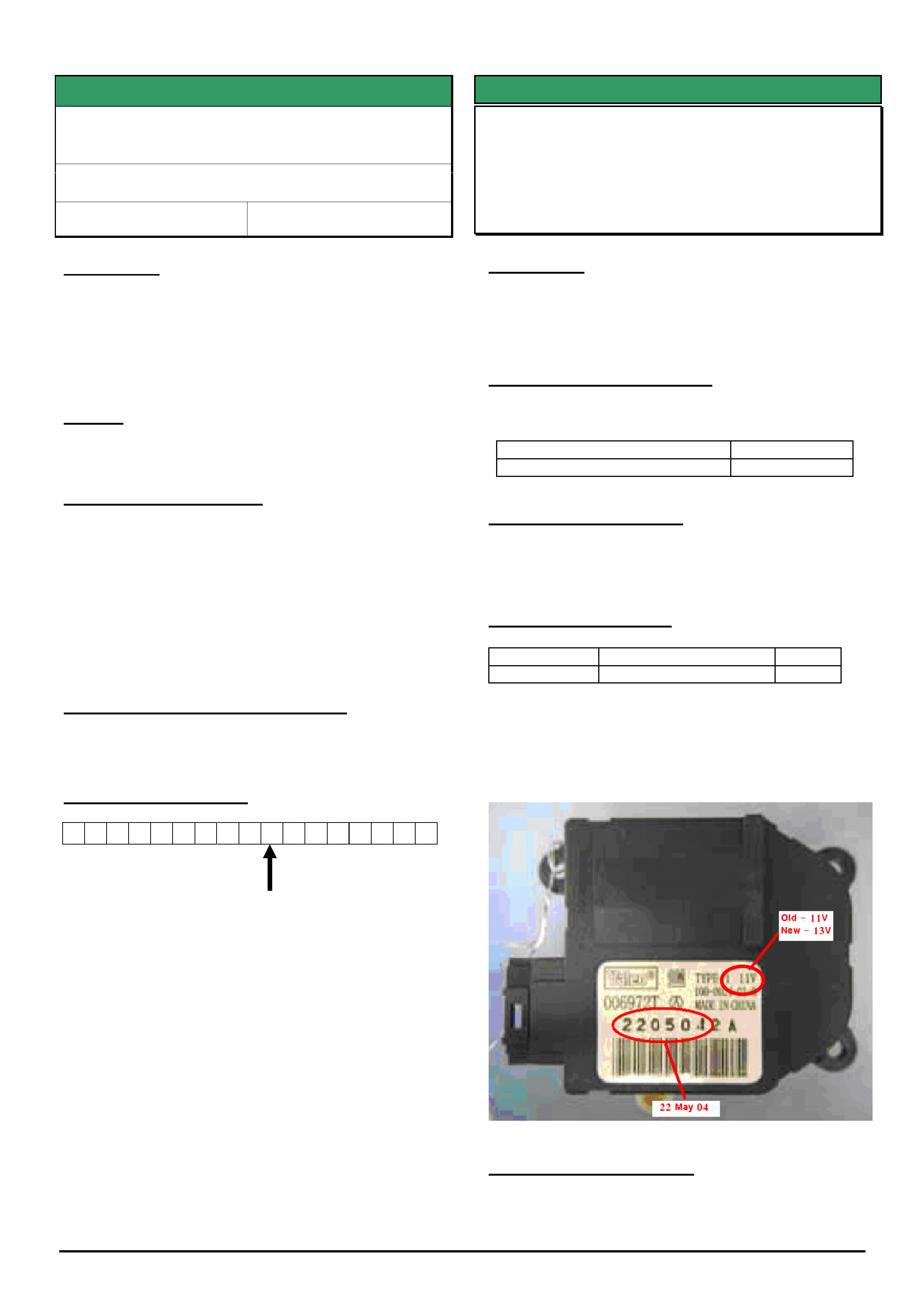
HOLDEN SERVICE TECHLINES_________________________________________________________________________________JUNE, 2006
15
Holden Techlines are written to inform technicians of conditions that may occur on some vehicles, and to provide information that could assist in the
proper service fix of a vehicle. If a condition is described, do not assume the service fix applies to a vehicle or that the vehicle will have that condition.
SERVICE FIX
Auto. Trans. Shift Improvement with Cruise
Control Engaged
VZ Adventra Model Year 06 with V6
Group 7B Ref. No. TL1114 - 0605
CONDITION
Customers may complain that, while cruise control is
engaged, their vehicle:
• holds an unnecessarily low gear on hills;
• overshoots the set speed on hill crests;
• holds a low gear for too long.
CAUSE
Transmission calibration.
CORRECTION – Service
Should the customer complain, and after verifying that
vehicle has condition as described above, reflash the
PCM with the latest software from TIS 2000 Version
71.0 (or later).
Calibration detail:
92192030 – VZ Adventra, Non-SX6 (replaces 92189905)
92192031 – VZ Adventra, SX6 (replaces 92189906)
WARRANTY CLAIM INFORMATION
Use Labour Times information in Warranty Information
section of current PV SIP CD
Model Year Identification
6 G 1 Z K 5 2 B 0 6 L 8 7 6 5 4 3
Model Year Code: 6 = 2006
SERVICE FIX
HVAC Air Recirculation Door Servo Motor
Clicks Continuously
ZC Vectra
(GROUP 2) TL1139-0605
CONDITION
A continuous clicking noise may be heard from the
HVAC case area when recirculation is turned on. This
may be caused by internal gear failure in the recirc
door motor.
CORRECTION – Production
Revised recirculation door servo motor with improved
internal gears has been fitted in production from:
ISOVIN: Built Date:
W0L0ZCF6861035268 21/10/05
CORRECTION – Service
Once this has been confirmed as the cause of the
noise, replace the recirculation door motor with a
revised part. Do not fit old level parts.
PARTS INFORMATION
Part No.: Description: Qty:
13192013 Motor- servo, air flap 1
The part number for the servo motor has not changed.
The old parts have 11V printed on the label in the top
right corner. The revised parts have 13V printed in the
same location and a date stamp of 10/10/05 or later.
Refer to figure 1.
Figure 1
WARRANTY INFORMATION
Use standard Labour Times found in the Warranty
Information section of the current PV SIP disc.

HOLDEN SERVICE TECHLINES_________________________________________________________________________________JULY, 2006
5
Holden Techlines are written to inform technicians of conditions that may occur on some vehicles, and to provide information that could assist in the
proper service fix of a vehicle. If a condition is described, do not assume the service fix applies to a vehicle or that the vehicle will have that condition.
SERVICE FIX
Trip Computer Fuel Readings Inaccurate
VZ
Group 12 Ref. No. TL1149 - 0606
CONDITION
Customers may advise their trip computer average fuel
and average speed displays are inaccurate.
For example, some customers have advised the
average fuel value displayed by their instrument cluster
is 99.9 litres per 100 km and the average speed
displayed is approximately 4.5 km/h.
CAUSE
This condition may be caused by incorrectly
programming the instrument cluster configuration.
CORRECTION – Vehicle Production
Vehicles built from the 18th of May 2006 have been
confirmed to be programmed correctly.
CORRECTION – Vehicles In Service
Summary: After verifying that vehicle has condition as
described above, program the correct PPK value using
Tech 2.
1. Using Tech 2 check the instrument cluster
configuration list to ensure the PPK value has
been programmed correctly.
2. Road test the vehicle to confirm the customer
complaint has been rectified.
WARRANTY CLAIM INFORMATION
Use standard Labour Times found in the Warranty
Information section of the current SIP disc.
INFORMATION
Central Locking Remote Battery
Replacement
JF Viva & TK Barina
Group 12 Ref. No. TL1147 - 0606
When required during scheduled servicing, the above
vehicles require the central locking remote batteries to
be replaced.
The battery required for a JF Viva is CR1616 and is
available from HSPO.
The battery required for the TK Barina is CR1620 and
is not available from HSPO. This battery will need to
be sourced from your local electrical retailer.
CR1616 and CR1620 are not interchangeable
because they are different thicknesses.
DON’T TRY TO MAKE THE WRONG BATTERY FIT !

HOLDEN SERVICE TECHLINES_________________________________________________________________________________JULY, 2006
6
Holden Techlines are written to inform technicians of conditions that may occur on some vehicles, and to provide information that could assist in the
proper service fix of a vehicle. If a condition is described, do not assume the service fix applies to a vehicle or that the vehicle will have that condition.
DIAGNOSIS HINT
SRS Light Illuminates and DTC 161 sets in
the SRS module
VZ / WL
Group 12 Ref. No. TL1146 - 0606
CONDITION
Customers advise the SRS light has illuminated after
the vehicle battery voltage has been low.
A check with Tech 2 reveals that DTC 161
“Configuration Mismatch” is set in the SRS module
CAUSE
This DTC may set for several reasons listed below,
1. When the SRS configuration programmed in the
instrument cluster is different from that
programmed in the SDM.
2. If the instrument cluster is disconnected from the
vehicle and the ignition is cycled.
3. If the battery voltage is low enough for the
instrument cluster to switch off but the SDM to be
still powered and the ignition is cycled.
CORRECTION – Vehicles In Service
Discuss with the customer the events prior to the SRS
light illuminating,
1. Check the instrument cluster configuration is
correct for the vehicle and if incorrect, rectify.
2. Check if the instrument cluster has previously been
removed and the ignition cycled (e.g. visited a
panel shop).
3. Check if the vehicle battery voltage has been low
or if the vehicle has required jump starting.
Don’t just clear the DTC. Determine what caused the
DTC to set. Once cause is rectified, then clear the DTC.
DIAGNOSIS HINT
Electronic Throttle Control, DTC P1555
TS, AH Astra
Group 6C Ref. No. TL1047 - 0606
PROBLEM DESCRIPTION
Customer may complain of check engine light coming on
intermittently and/or reduced engine power. This fault
may be very intermittent.
A DTC check may indicate a history fault code as follows:
DTC P1555 Throttle Position Sensor – Load signal not
plausable with Engine Load.
This DTC may not be easily reproduced on a roadtest.
DIAGNOSIS HINT
This is a reminder to technicians that DTC P1555 is a
“calculated” DTC based on mass airflow, engine load
and current throttle position. It does not necessarily
mean a fault with the electronic throttle body or
associated wiring.
POTENTIAL CAUSE
DTC P1555 is often caused by restrictions or leaks into
the air intake system, before or after the mass airflow
meter. It may also be caused by the airflow meter being
inadvertantly reinstalled back-to-front.
SUGGESTED ACTION
• Ensure the mass airflow sensor is installed facing in
the correct direction by inspecting the arrow which
indicates the direction of air flow through the sensor.
• Check the entire air intake system, including the air
filter and the air box intake, for leaks or restrictions
caused by leaves or bags etc.
• If all the above checks are ok, follow standard
diagnosis as per TIS.
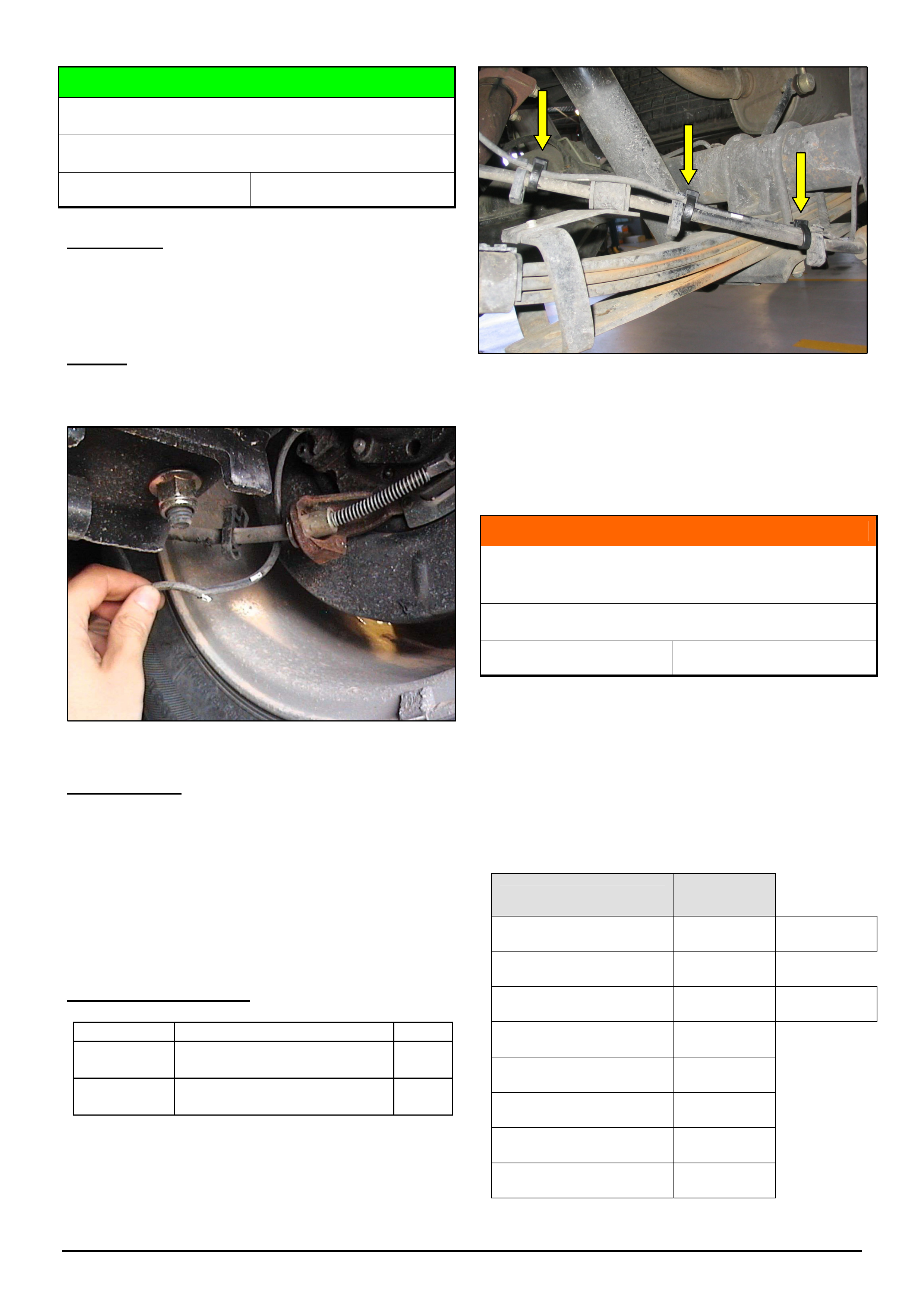
HOLDEN SERVICE TECHLINES_________________________________________________________________________________JULY, 2006
9
Holden Techlines are written to inform technicians of conditions that may occur on some vehicles, and to provide information that could assist in the
proper service fix of a vehicle. If a condition is described, do not assume the service fix applies to a vehicle or that the vehicle will have that condition.
SERVICE HINT
Rear Wheel Speed Sensor Damage
VY,VZ, One Tonner & Crewman with ABS
Group 5 Ref. No. TL1108 - 0606
CONDITION
The warning “ABS Fault" displays in instrument
cluster, ABS inoperative, DTC C0045 or DTC C0050
present.
CAUSE
The wheel speed sensor harness may be dislodged or
damaged by road debris
Figure 1. Damaged wheel speed sensor harness
CORRECTION
1. After verifying that vehicle has condition as
described above, install a new "Sensor Asm - rear
wheel speed."
2. To ensure retention of sensor harness, attach 3
cable-ties (92138082) adjacent to the 3 retainer
clips as shown in Figure 2.
PARTS INFORMATION
Part No.: Description Qty:
Refer
Microcat
Sensor Asm – rear wheel
speed
1
92138082 Cable tie
3
Figure 2. Add 3 cable ties as shown.
INFORMATION
V8 Engine Identification by Engine Number
Prefix
V & W Series – 5.7/6.0 litre V8
Group 6A Ref. No. TL1087 - 0606
Technicians may have difficulty identifying V8 engine
types, for diagnosis of any problems, or procuring parts,
etc, as the V8 engines - LS1 (5.7 litre), L76 (6.0 litre),
LS2 (HSV 6.0 litre) and L98 (6.0 litre) - look similar.
The following table defines V8 engine number prefixes
that are stamped on 5.7 or 6.0 litre V8 engines, to help
identify the type of engine being worked on:
Engine Type Engine No.
Prefix
LS1 (5.7 litre) VF * Purge Valve
behind T/body
L76 (6.0 litre) 6MB
LS2 HSV (6.0 litre) VF * Purge Valve
above Eng No.
L98 (6.0 litre) – VZ A/T 7NB
L98 (6.0 litre) – VZ M/T CAK
L98 (6.0 litre) – VE A/T 7NC
L98 (6.0 litre) – VE M/T 7ND
LS2 HSV (6.0 litre) - VE ZLF
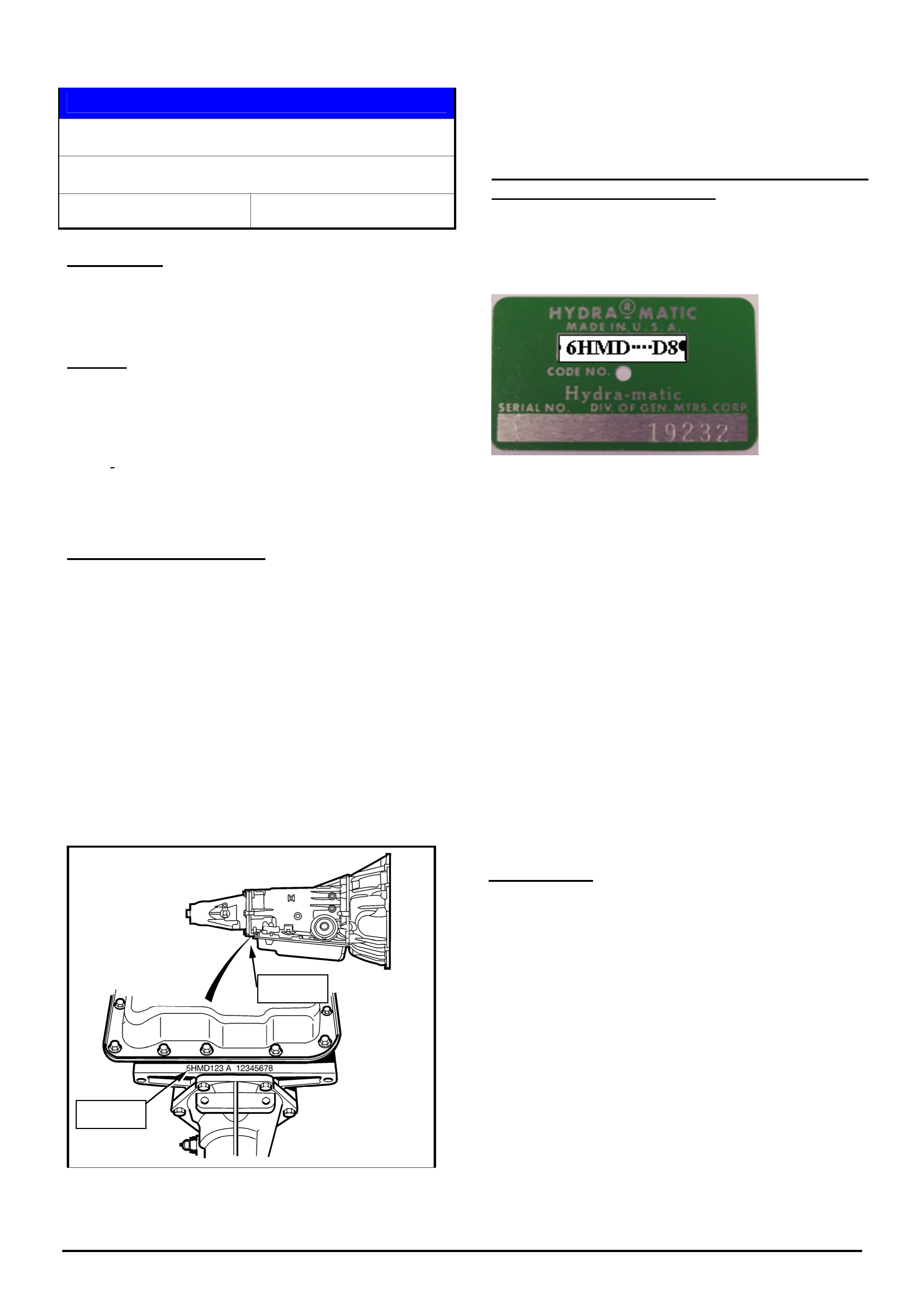
HOLDEN SERVICE TECHLINES_________________________________________________________________________________JULY, 2006
10
Holden Techlines are written to inform technicians of conditions that may occur on some vehicles, and to provide information that could assist in the
proper service fix of a vehicle. If a condition is described, do not assume the service fix applies to a vehicle or that the vehicle will have that condition.
SERVICE PROCEDURE
Correct A/T Identification for SRTA Requests
VY, VZ, WL, V2, RA, VE, WM
Group 7B Ref. No. TL1148 - 0606
CONDITION
Incorrect SRTA exchange transmissions are being
received at Dealerships from SRTA.
CAUSE
Incorrect identification of transmission type requested
by Dealership personnel via incomplete/incorrect
information on SRTA TRANSMISSION ORDER FORM.
NOTE: Transmission serial numbers no longer carry
serial numbers that coincide with vehicle build date or
model year.
CORRECT PROCEDURE
(1). Vehicles with Original Equipment (OE)
Transmission:
The transmission serial number as read
off the transmission case must be
provided to SRTA to ensure that a correct
exchange transmission will be supplied.
The following diagram shows the location of the
transmission serial number – for recording on the
SRTA TRANSMISSION ORDER FORM:
(2). Vehicles fitted with a SRTA Transmission:
Transmission ID/Serial number location For
SRTA Transmissions ONLY
SRTA transmissions are identified by a GREEN plate
attached to the RH side of the transmission case with
the word “Hydramatic” at the top of the plate.
For Reference only: ACDelco® remanufactured
transmissions are identified by a BLUE plate attached to the
RH side of the transmission case with the word ACDelco at
the top of the plate.
Both of these plates “over-ride” the O.E. number
stamped on the trans. case, and include: Model
Identifier, Julian Date and Individual Transmission
Serial No. (as mentioned above).
This information MUST be used where a SRTA
transmission suffers a failure requiring replacement of
the unit. Warranty acceptance on such a unit is
defined by distance travelled, or date of fitting the unit
to date of failure (24 month/50000km parts warranty
applies).
NOTE: Both SRTA and ACDelco remanufactured
transmissions are painted silver and OE transmissions
are unpainted, plain cast alloy.
SRTA Action
SRTA will no longer supply exchange transmissions
based solely on either model or ISOVIN numbers
supplied on a SRTA TRANSMISSION ORDER FORM.
Forms supplied without serial numbers from the
transmission – as noted above - will not be honoured
and the Dealer will be requested to arrange for the
serial number – RECORDED FROM THE VEHICLE -
to be supplied.
To avoid customer inconvenience, ensure
that the transmission serial number is
recorded when the transmission is first
diagnosed as requiring replacement.
Serial No.
Serial No.
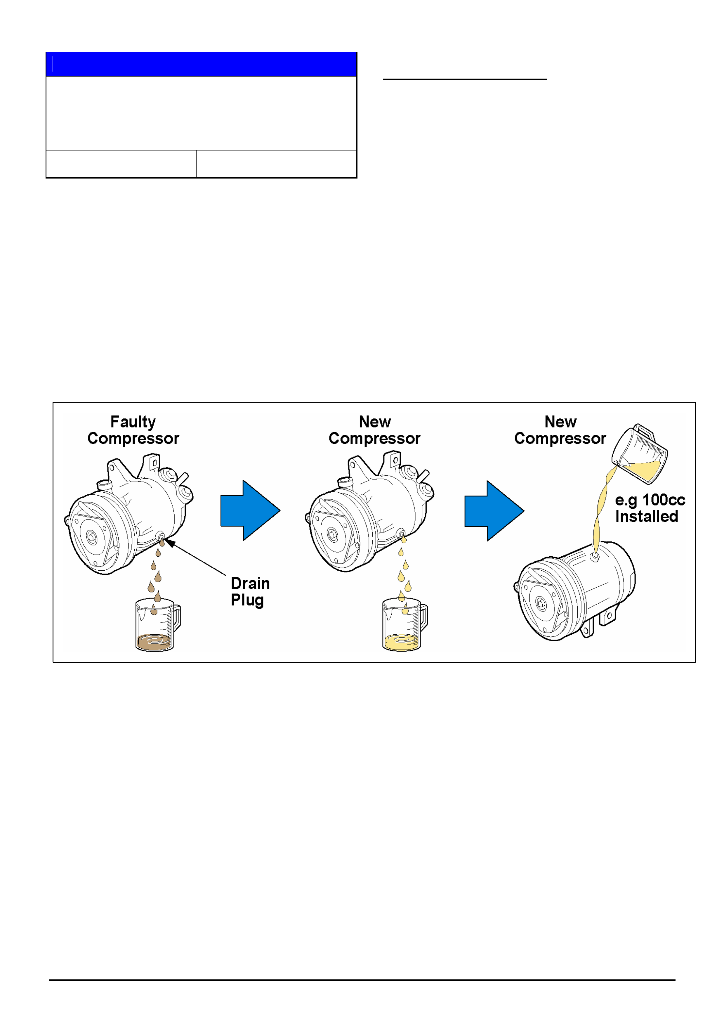
HOLDEN SERVICE TECHLINES_________________________________________________________________________________JULY, 2006
11
Holden Techlines are written to inform technicians of conditions that may occur on some vehicles, and to provide information that could assist in the
proper service fix of a vehicle. If a condition is described, do not assume the service fix applies to a vehicle or that the vehicle will have that condition.
SERVICE PROCEDURE
Installing New A/C Compressor - Oil Balance
Procedure
All
Group 2 Ref. No. TL1106 - 0606
A new compressor contains a complete A/C system oil
charge.
Therefore, whenever a compressor is replaced, the
following procedure must be performed in order to
maintain the correct amount of compressor lubricant in
the system.
DO NOT install a new compressor without first
performing the oil balance procedure.
OIL BALANCE PROCEDURE
STEP 1. Drain and measure (and record) the quantity
of oil removed from the old compressor.
STEP 2. Drain the oil from the new compressor into a
clean measuring container.
STEP 3. Refill the new compressor with the new oil
removed in step 2, but using the same quantity as
drained from the old compressor in step 1.
NOTE: In cases where a refrigerant hose has blown or
a compressor housing is cracked, the complete A/C
system will have to be flushed to remove all traces of
oil and foreign material. The new compressor can then
be installed with no oil balance check required.
Step 1.
Drain, measure, and record
the quantity of oil removed
from the old compressor.
Step 2.
Drain the oil from the new
compressor into a clean
measuring container.
Step 3.
Refill the new compressor with
the new oil removed in step 2,
but using the same quantity as
drained from the old compressor
in step 1.
HOLDEN SERVICE TECHLINES_________________________________________________________________________________JULY, 2006
12
Holden Techlines are written to inform technicians of conditions that may occur on some vehicles, and to provide information that could assist in the
proper service fix of a vehicle. If a condition is described, do not assume the service fix applies to a vehicle or that the vehicle will have that condition.
SERVICE FIX
Sluggish On Takeoff and/or Transmission
Thumps After Takeoff
VYII, WKII, Gen 3 A/T only
Group 7B Ref. No. TL1132 - 0606
CONDITION
Customers may complain that intermittently their car is
sluggish on take off, feeling like it may not be in 1st
gear. The transmission may also “thump” as it
downshifts from 2nd to 1st gear shortly after takeoff.
This fault is very intermittent and may not easily be
reproduced by the dealer.
CAUSE
It is caused by erratic transmission output shaft speed
signal to the PCM at low speed, causing the vehicle to
initially take off in 2nd gear.
A revised calibration is available via TIS 2000 Version
72.0.
CORRECTION – Service
On any vehicle with the above symptoms, the following
must be performed.
Re-program the ECU or PCM (engine or powertrain
control module) as per the standard SPS (Service
Programming System) process using Tech 2 and TIS
2000 version 72.0 or later.
NOTE: For detailed instruction on this process refer to
Holden Lionheart portal - Service Techlines\ TIS 2000\
Programming Procedures\ “Engine ECU/PCM SPS”.
WARRANTY CLAIM INFORMATION
Use standard Labour Times found in the Warranty
Information section of the current SIP disc.
Reverse Mount Wheels
HSV VZ Series
Group 10 Ref. No. TL1150 - 0606
HSV have released a new “Reverse Mount” wheel on
selected models. With this wheel the tyre must be
removed / fitted over the rear flange of the wheel.
For more details, refer to HSV Bulletin 052/06 which
can be found on the Lionheart portal. Look in Service
Bulletins / Service Techlines / HSV / Group - 10 .
DIAGNOSIS HINT
Engine Stalls, DTC P0100 and/or P0110 set
TS with X18XE1
Group 6C Ref. No. TL1130 - 0606
CONDITION
Engine stalls and trouble code P0100 and/or P0110 is
set.
On any vehicle that experiences the above symptoms,
refer to Opel Field Remedy 2033 which may be found
in TIS 2000 version 72.0 onwards.
Field Remedy 2033 gives details of a procedure for the
installation of additional earths to the engine ECU.
The pathway to Field Remedy 2033 is as follows:
Select Service Information
Select Salesmake - Opel
Select Astra – G
Select Direct Document Search
Select Technical information
In the search window type - “E0002033”. (this will
take you directly to Field Remedy 2033).
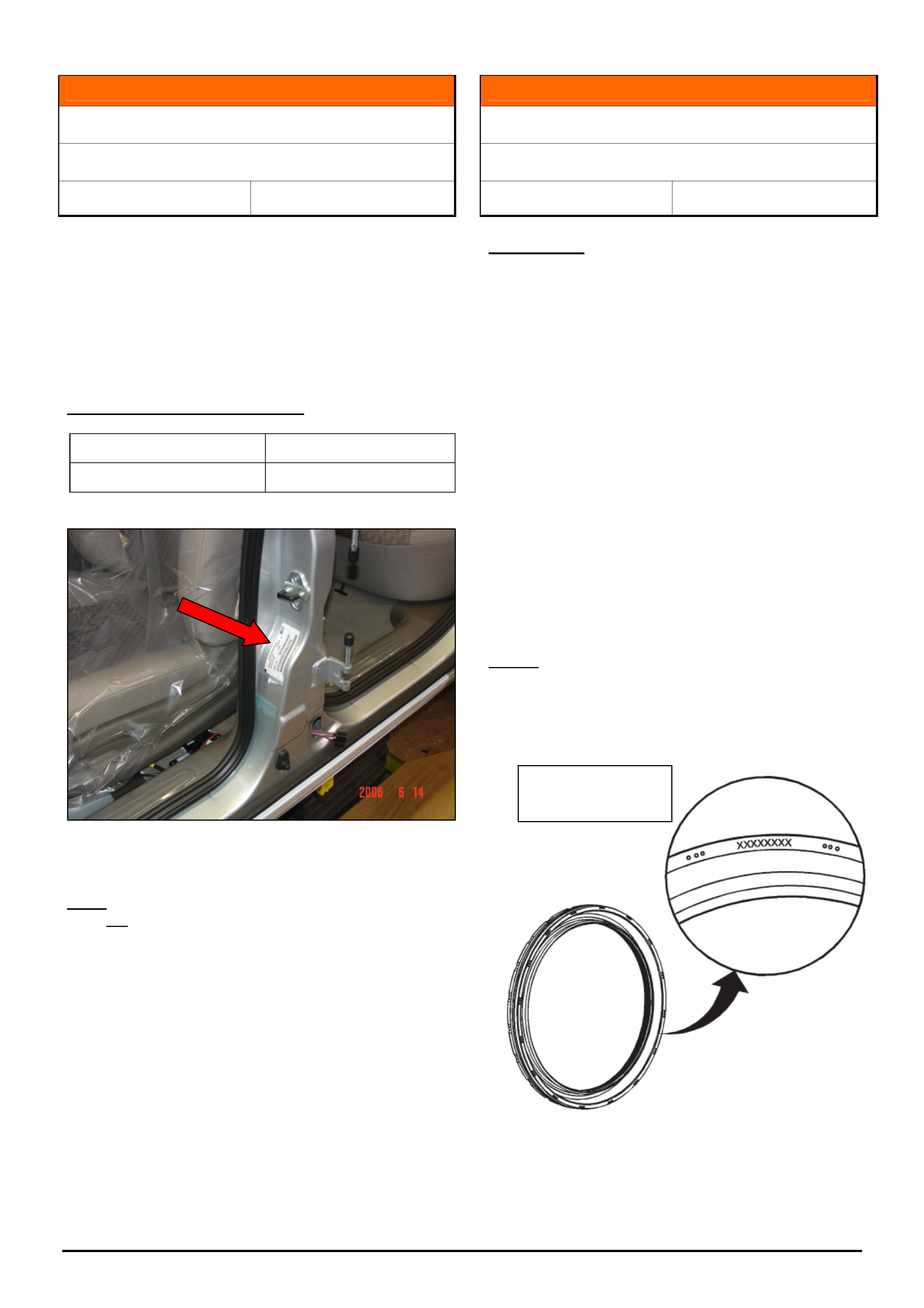
HOLDEN SERVICE TECHLINES_____________________________________________________________________________AUGUST, 2006
5
Holden Techlines are written to inform technicians of conditions that may occur on some vehicles, and to provide information that could assist in the
proper service fix of a vehicle. If a condition is described, do not assume the service fix applies to a vehicle or that the vehicle will have that condition.
INFORMATION
Compliance Identification Changes
WL, VZ (Ute, Crewman, Wagon)
Group 1 Ref. No. TL1151 - 0607
Technicians and dealer staff should be aware that
recently the location and type of compliance
identification has changed. The riveted plate under the
bonnet has been replaced with an adhesive label
located on the Left Hand B Pillar, just below the door
striker. An example of the new style label is shown in
figure 1.
PRODUCTION BREAK POINT
Tag Date
L845299 28-06-06
Figure 1.
Note: The date shown on this label is the compliance
date, not the built date. The built date is shown on the
body and option plate.
INFORMATION
Introduction of Reverse Lip Rear Main Seal
V & W – with Alloy V8 Engine
Group 6A Ref. No. TL1140 - 0607
CONDITION
V8 engines are now being built with a new style
“reverse lip” rear main oil seal.
This seal can be fitted to all previously built engines
whenever replacement is necessary.
Don’t be confused!
Technicians should note that the installed seal has the
appearance of the previous type seal being installed
backwards (BUT – you will be able to read the part
number – see below).
Installation Instructions:
This seal is assembled in the same manner, and with
the same special tool as the previous seal.
No procedures are changed by the introduction of this
new design seal.
Identification:
The reverse lip seal has the part number applied to the
outside face of the seal as shown in the diagram below.
This diagram is from the Installation Instructions that
are included in the packaging with a new seal:
Part No. must
face outwards

HOLDEN SERVICE TECHLINES_____________________________________________________________________________AUGUST, 2006
6
Holden Techlines are written to inform technicians of conditions that may occur on some vehicles, and to provide information that could assist in the
proper service fix of a vehicle. If a condition is described, do not assume the service fix applies to a vehicle or that the vehicle will have that condition.
INFORMATION
Two Stage Unlock - Programming
ZC Vectra, MY 2004.5 onwards
(GROUP 12) TL1157-0607
To switch between single and two stage unlock
perform the following steps:
1. Remove key from the ignition.
2. Locate the ‘all doors lock/unlock’ button on the
driver’s door.
3. Press and hold this button down, then hold
down the ‘unlock’ button on the remote key.
4. Continue to hold these buttons until a double
beep is heard. The beeps are to confirm the
programming has been successful.
5. Use the remote to confirm the change in
operation.
NOTE: When holding the buttons down in step 4, the
comfort opening feature (all windows drop) may
operate. This is normal when changing this feature.
To disable the Two Stage Unlock feature, repeat the
same procedure as above, although only a single beep
will be heard.
It will be important to ask the customer if they
would like both keys to operate in the same way. If
so, both keys will need to be present to program as
this feature is linked to each individual remote.
INFORMATION
Vehicle Speed Locking Feature
ZC Vectra, MY 2004.5 onwards
(GROUP 12) TL1160-0607
From 2004.5 model year, the “Speed Locking” feature
was added to ZC models. With this feature, the doors
and luggage compartment can be set to lock at a pre-
determined vehicle speed.
To activate this feature perform the following steps:
1. Remove key from the ignition.
2. Locate the ‘all doors lock/unlock’ button on the
driver’s door.
3. Press and hold this button down, then hold
down the ‘lock’ button on the remote key.
4. Continue to hold these buttons down until a
double beep is heard. The beeps are to confirm
the programming has been successful
5. Drive the vehicle with the doors unlocked to
confirm the change in status when the pre-
determined vehicle speed is reached.
NOTE: When holding the buttons down in step 4, the
comfort closing feature (all windows lift) may operate.
This is normal when changing this feature.
All doors and the luggage compartment will be
unlocked when the ignition is switched to the off
position or when the ‘all doors lock/unlock’ button is
depressed.
To disable this feature, carry out the same procedure
as above, although only a single beep will be heard.
It will be important to ask the customer if they
would like both keys to operate in the same way. If
so, both keys will need to be present to program as
this feature is linked to each individual remote.
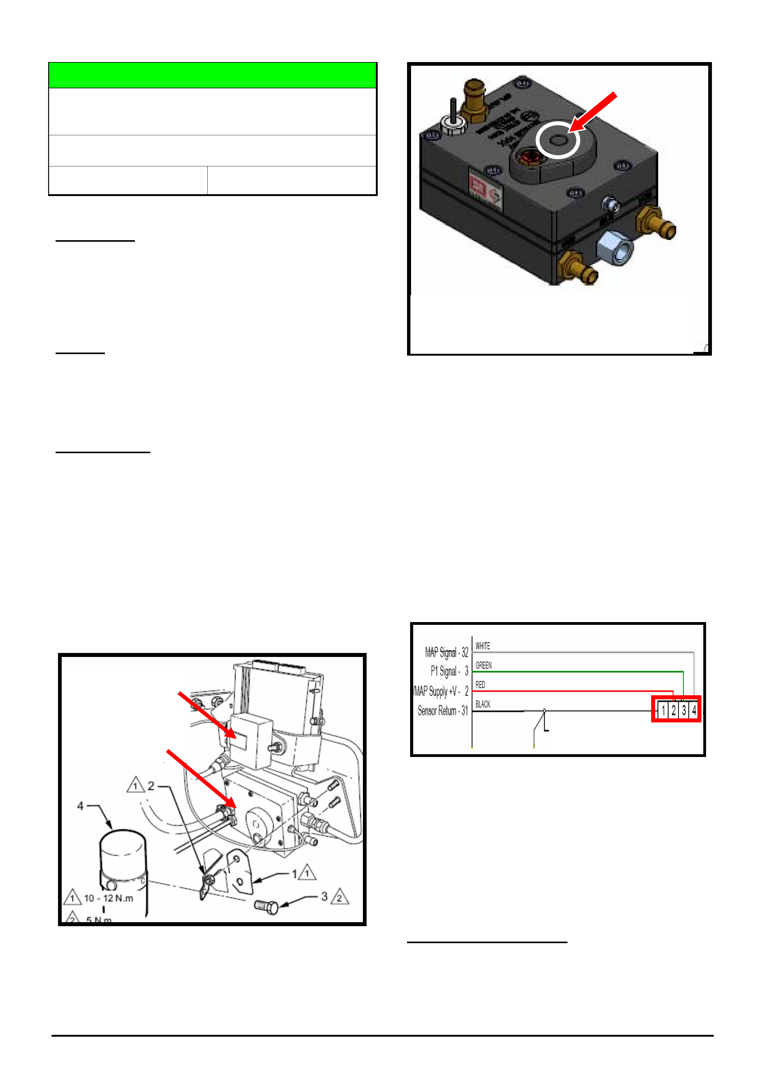
HOLDEN SERVICE TECHLINES_____________________________________________________________________________AUGUST, 2006
7
Holden Techlines are written to inform technicians of conditions that may occur on some vehicles, and to provide information that could assist in the
proper service fix of a vehicle. If a condition is described, do not assume the service fix applies to a vehicle or that the vehicle will have that condition.
DIAGNOSIS HINT
Engine Automatically Reverts To Petrol After
Running On LPG For Several Seconds
VZ with LPG
Group 6M Ref. No. TL1155 - 0607
CONDITION
When vehicle is running on petrol and then switched
over to LPG, it may only run for several seconds before
switching back to petrol by itself. The LPG/Fuel
selection switch will beep.
CAUSE
The above condition can be caused by the LPG
Manifold Air Pressure (MAP) sensor adjustment not set
to specification.
CORRECTION
After verifying the vehicle has same condition as
described above, proceed to adjust the MAP pressure
as follows.
1. The adjusting screw is located on the LPG
converter which is mounted underneath the LPG
computer. The heat shield requires removal to
gain access to the adjusting screw.
Refer figures 1 & 2
Figure 1
Figure 2
2. Locate the wiring connector on the MAP sensor,
connect a multimeter to the green & white wires
and while turning the adjusting screw set the
voltage to 3.6 – 3.7 volts. Turn screw clockwise
to increase the voltage and anticlockwise to
decrease voltage.
IMPORTANT: This adjustment must be done
with the engine idling in LPG mode.
3. Reinstall plastic plug to cover adjuster screw
and refit the protective heat shield.
4. Confirm the complaint condition is rectified
The above MAP sensor circuit diagram is extracted
from the LPG Harness Wiring Diagram in SIP.
Refer – MY 2005 Service Information
- Fuel & Exhaust Systems
- Section 8A2 VZ LPG Conversion kit
- Service & Diagnostics
- Wiring Schematics
Alternative Procedure
As an alternative to the above, for those dealers with
the Sequent diagnostic software Interface, correct
Delta P setting during operation at idle is 1500 millibar.
LPG
ECU
LPG ‘MAP’ sensor
LPG Converter
Remove cover plug to access adjusting screw.
Turn clockwise to increase voltage,
anticlockwise to lower voltage.
MAP Sensor connector
White Wire
Green Wire
Adjusting
Screw
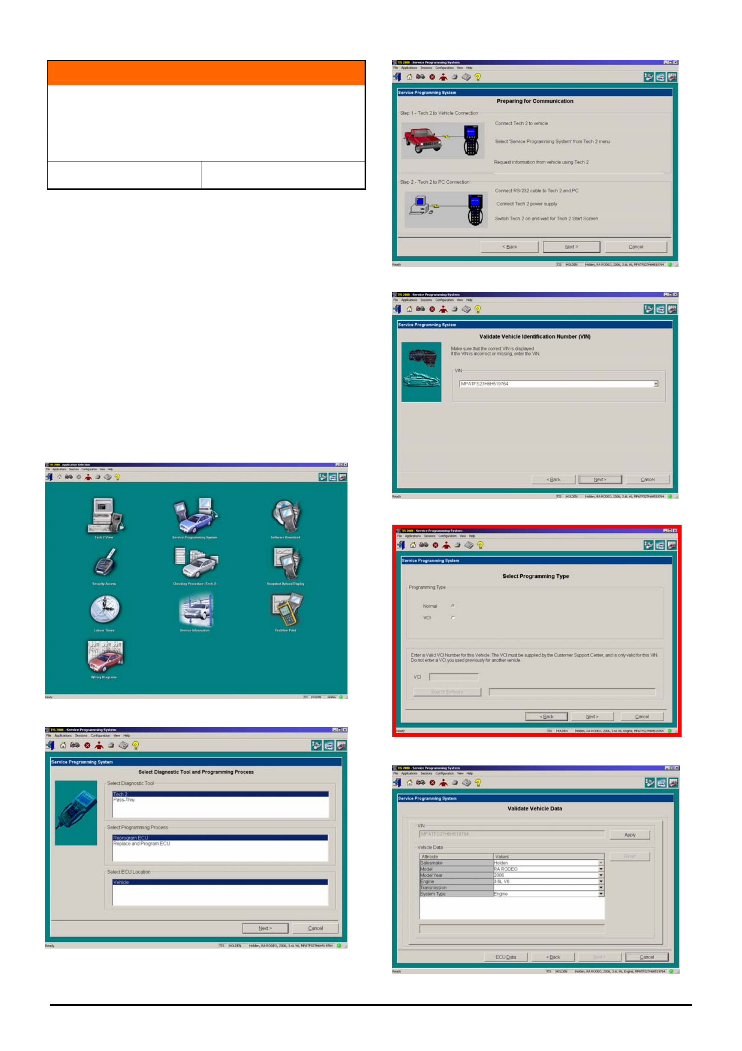
HOLDEN SERVICE TECHLINES_____________________________________________________________________________AUGUST, 2006
8
Holden Techlines are written to inform technicians of conditions that may occur on some vehicles, and to provide information that could assist in the
proper service fix of a vehicle. If a condition is described, do not assume the service fix applies to a vehicle or that the vehicle will have that condition.
INFORMATION
Vehicle Configuration Index (VCI) Process
Added To SPS
TIS 2000 Version 73 Onwards
Group OB Ref. No. TL1159 - 0607
The Service Programming System (SPS) menu has
been revised (as shown below) with the release of TIS
2000 version 73 and now includes a new selection
called Vehicle Configuration Index (VCI).
This new selection should only be used when instructed
by TAS. It will enable calibrations not included on TIS
2000 to be programmed into specific control modules via
the SPS process.
When the selection screen appears it will default to
normal. Select the next option, unless requested by TAS
and continue programming in the usual manner.
Below are copies of the SPS selection screens.
Screen 5 (bordered in red) is the new VCI screen.
Screen 1
Screen 2
Screen 3
Screen 4
Screen 5
Screen 6

HOLDEN SERVICE TECHLINES_____________________________________________________________________________AUGUST, 2006
9
Holden Techlines are written to inform technicians of conditions that may occur on some vehicles, and to provide information that could assist in the
proper service fix of a vehicle. If a condition is described, do not assume the service fix applies to a vehicle or that the vehicle will have that condition.
INFORMATION
Description Of HVAC and A/C System Changes for VE
VE
Group 2 Ref. No. TL1145 - 0607
The following information has been supplied by Air International, supplier of the air conditioning
system for the new VE models.
The new VE Heating and Air conditioning system has a number of significant improvements compared to
the previous VZ Heating and Air conditioning system. These are listed below:
The vacuum actuators used to operate vent mode positions and temperature adjustment are
discontinued and electric actuators are now used for each mode and temperature adjustment
There are now three (3) different levels of the HVAC. They are Single Zone (S.Z), Dual Zone (D.Z) and
Tri Zone (T.Z)
The newly added Tri zone (T.Z) has an electric actuator that adjusts both temperature and air flow
direction (rear console vent and floor) to the rear passengers via a separate rear control
The VE electric actuators use photo interrupters ( potentiometers in VZ ECC) for door feed back
position. The VE actuator is quieter and more responsive. The actual position of the doors and
movement can now been viewed and checked using the scan tool.
Evaporator sensor is supplied as part of the HVAC wiring harness.
The VE evaporator is larger in overall size and thickness is reduced to 38 mm (VZ 68mm) The increase
in size improves performance, and the reduction in thickness reduces overall weight of the HVAC
assembly.
Temperature split in Bi-level mode and the mode change strategy has been improved.
A permanent air bleed to the side windows in face and demist mode has been added to ensure no
frost / mist build up on the window glass.
Improved HVAC case assembly - less joints to avoid air noises and condensate leaks.
A HVAC Command Module (HCM) located at the passenger side blower housing area of the HVAC is
now used. The HCM controls mode positions, temperature adjustment, A/C compressor output
(displacement) via the ECV (electronic control valve in the compressor) and the blower fan speeds.
The HCM, if replaced as a spare part would have to be configured to suit the vehicle as the HCM is
provided as a T.Z spare part – only
The compressor is “clutch less” and operates continuously. It uses an ECV (electronic control valve)
that is connected to the HCM (HVAC Control Module). The HCM will vary the voltage to the ECV which
will then alter the stroke (displacement) when required. There is no electrical connection to the
compressor clutch.
HOLDEN SERVICE TECHLINES_____________________________________________________________________________AUGUST, 2006
10
Holden Techlines are written to inform technicians of conditions that may occur on some vehicles, and to provide information that could assist in the
proper service fix of a vehicle. If a condition is described, do not assume the service fix applies to a vehicle or that the vehicle will have that condition.
DESCRIPTION OF HVAC AND A/C SYSTEM CHANGES FOR VE – continued.
In VE, higher air flow is available from the HVAC vents owing to less restrictive internal passages,
upgraded blower motor output and improved HVAC internal door design. Air flow has increased from
120 litres a second to 142 litres a second. The blower motor also has improved sound quality and the
current draw is less than VZ.
The blower speed resister or amplifier is no longer a separate component. In VE, the blower speed
resister or amplifier is part of the heat sink located in the HCM.
Recirculation mode has two (2) settings for the duration the recirculation door is closed. The duration is
altered depending on ambient temperature. (above and below 30 degrees C)
Recirculation has a partial mode that is automatically selected as part of normal operation. It is
designed to purge CO2 build up, and allow a mixed mode to enable good performance whilst
maintaining some fresh air.
For the A/C system “plumbing”, slim line sealing washers are used instead of rubber o’rings at all joints
including the TX Valve to evaporator. The slim line washer has far superior sealing quality compared to
the rubber o’ring that could “rotate” during fitment.
The solar load sensor (ECC) now incorporates two (2) sensors; one (1) for passenger side and one (1)
for the drivers side of the vehicle.
A heater tap is no longer used; temperature control is via the HVAC air mixing flap which has
improved sealing capabilities.
A relearn of the minimum and maximum operating stop positions of the electric mode / temperature
actuators can be performed at any time by holding the rear window demist button down for 5 seconds
with the ignition “on”.
Refer next page for diagram of how the HCM (HVAC Control module) interacts via CAN Bus line to other
modules
IMPORTANT NOTE: PLEASE READ
“The flat sealing washers used for the TXV, tube joints, compressor, and
condenser MUST be installed in a DRY condition. No lubricating oil is to be
used as this will damage the rubber seal incorporated in the sealing washer,
this especially applies to using R12 mineral oil as it WILL cause the rubber
seal to swell and distort causing a refrigerant leak
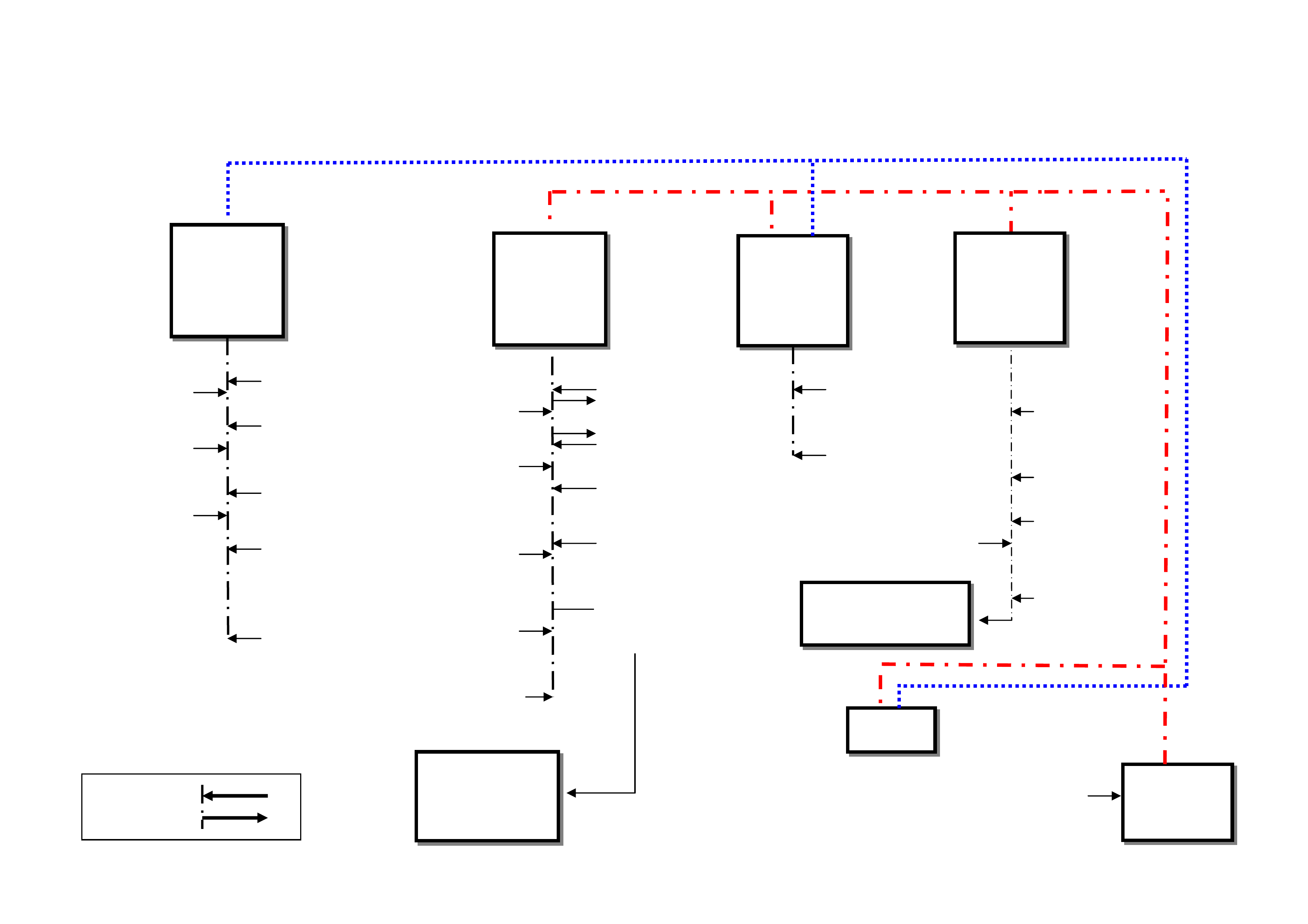
11
PCM
MODULE
A/C System
Pressure
Transducer
Engine
Cooling
Fans
Vehicle Road
S
p
eed
Engine RPM
Engine Coolant
Tem
p
erature
A/C
Compressor
Off Request
Supply
Volta
g
e
Max A/C
Compressor
Displacement
IPC
BCM
MODULE
DLC
Dual Wire CAN
T.Z Rear Mode /
Temp Control
Secondary Power
Circuit To HCM
Primary
Power Circuit
To HCM
Heated
Rear
Window
Ambient
Reading
Display
Mode Vent
Positions
Blower Fan
S
p
eeds
Set (by owner)
Temperature
Adjustments
A/C
Compressor
On /Off
Request
Signal In
Signal Out
Solar Load
Sensor
In Car
Temperature
Sensor
Evaporator
Tem
p
erature Sensor
Blower Fan Speeds
HVAC Mode Positions
via Electric Actuators
Supply Voltage
Ignition/Battery
Ambient
Temperature
Sensor
Rear Demist
Relay
A/C
Compressor
Output
Compressor
Output. ECVD
Target Position
Compressor
Output. ECVD
Actual
HCM
MODULE
IRC
MODULE
HCM (HVAC Control module) INTERACTION VIA CAN BUS LINE TO OTHER MODULES
Single Wire
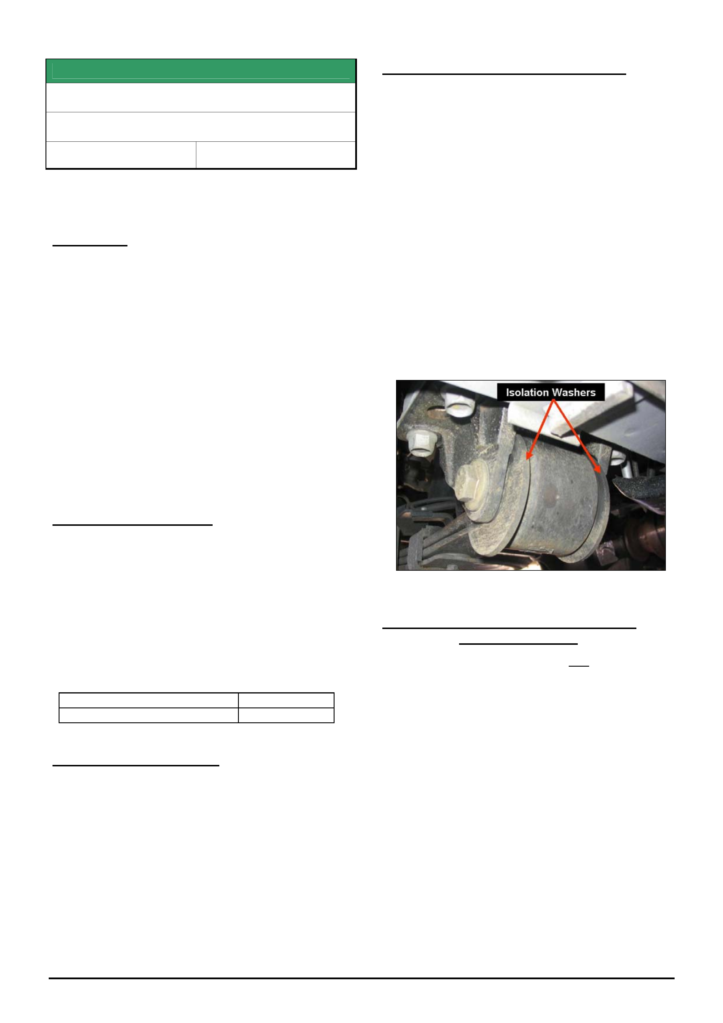
HOLDEN SERVICE TECHLINES_____________________________________________________________________________AUGUST, 2006
12
Holden Techlines are written to inform technicians of conditions that may occur on some vehicles, and to provide information that could assist in the
proper service fix of a vehicle. If a condition is described, do not assume the service fix applies to a vehicle or that the vehicle will have that condition.
SERVICE FIX
Diff. Period Whine, 80 – 110 km/h
VY & VZ – One Tonner & Crewman
Group 4 Ref. No. TL0631D-0607
This Techline supersedes the previous one in Issue 02, March,
2006. It is UPDATED by clarifying the application of service
fixes and models.
CONDITION
Some vehicles may experience an unacceptable
period whine noise from the differential at
approximately 80 - 110 km/h at light to medium throttle
cruising.
A certain level of rear axle assembly noise is normal
and to be expected on these light commercial type
vehicles due to their cab chassis structure and
associated load carrying requirements.
NOTES: This noise must not be confused with noises
resulting from possible faulty differential bearings or
gears.
All Wheel Drive (AWD) Models have axles with
different pinion flanges to Rear Wheel Drive (RWD)
models, thus the revised pinion flange mentioned
cannot be used – AWD models can have the front
spring eye bushes changed only.
PRODUCTION CHANGES
Crewman models have had two countermeasures
introduced into production only on the specific models
listed here:
• Crewman V8 (A/T & M/T), (RWD & AWD) - A
softer rubber bush in the front eye of the leaf
spring.
• Crewman V8 A/T (RWD only) - A 2-spoke pinion
flange.
Breakpoint for both the above countermeasures in
Crewman ONLY is:
ISOVIN: Built Date:
**********L218227 09/03/2004
CORRECTION – SERVICE
Summary:
PART 1. - For all beam axle vehicles,
Install revised rear spring front eye bushes if not
already fitted.
PART 2. - For RWD V8 (A/T & M/T) & RWD V6 (M/T
only)
Install a 2-spoke diff pinion flange and rear spring front
eye bushes if not already fitted).
PART 1. - For all beam axle vehicles.
Install revised rear spring front eye bushes if not
already fitted.
Procedure:
(For procedures not covered in detail, refer latest SIP DVD).
1. Remove rear springs.
2. Press out existing front spring eye bush from
each spring.
3. Press in new spring front eye bushes p/n
92148815.
4. Reinstall spring assemblies.
NOTE: The four large insulation washers p/n 92175916
are required to be fitted – one on each side of the front
spring eye bush as spacers/locators. These washers are
only fitted to vehicles with the revised spring eye bushes.
PART 2. - For RWD V8 (A/T & M/T) and
RWD V6 (M/T only)
Install a 2-spoke diff pinion flange and rear spring front
eye bushes (as noted in Part 1 above) if not already
fitted.
1. Revised pinion flange p/n 92176653 should be
fitted with a new nut p/n 92146565 exactly as per
procedure found in SIP: viz;
Section 4B – Final Drive & Drive Shafts,
2. Minor Service Operations,
2.11 Pinion Flange/Replace using old seal.
CAUTION: Overtightening or undertightening of
the pinion nut may result in excessive bearing
preload and bearing damage.
2. The alternative to Dealers doing step 1 is to have a
sublet repairer (diff specialist) fit the flange.
Any such repairer must use a torque reading
tension wrench to ensure the pre-load before and
after is the same - otherwise, preload related
noise/failure will occur at a later date.
HOLDEN SERVICE TECHLINES_____________________________________________________________________________AUGUST, 2006
13
Holden Techlines are written to inform technicians of conditions that may occur on some vehicles, and to provide information that could assist in the
proper service fix of a vehicle. If a condition is described, do not assume the service fix applies to a vehicle or that the vehicle will have that condition.
PARTS INFORMATION
Part No.: Description: Qty:
92148815 Bush Rr Spring Front 2
92175916 Washer
92176653 Pinion Flange
V8 (A/T & M/T), or
V6 (M/T only)
1
92146565 Flange Nut
V8 (A/T & M/T), or
V6 (M/T only)
1
WARRANTY CLAIM INFORMATION
Description Replace Bush, Leaf Spring
Front Eye – Both Sides
Labour Op. No. F000197
Time 1.6 hr.
Add for V8 & V6(M/T) Rear
Wheel Drive Only - Fitting
of revised Pinion Flange
0.5 hr.
Failure Code F0040 noisy
Terminology
A/T – automatic transmission. RWD – Rear wheel drive
M/T – manual transmission AWD – All wheel drive
INFORMATION
Engine Spigot (Pilot) Bearing
TK & JF with M/T
Group 7A Ref. No.: TL1156 - 0607
TAS has received calls from dealers asking if these
vehicles are fitted with a spigot (pilot) bearing.
These vehicles do not have a spigot (pilot) bearing
located in the crankshaft, as the manual transmission
input shaft is supported by two bearings internally.
Service information contained in SIP referring to pilot
bearings refers to an earlier design engine/vehicle.
Parts and Service personnel should not try to obtain or
fit spigot (pilot) bearings to the engines in these
vehicles.

HOLDEN SERVICE TECHLINES_____________________________________________________________________________AUGUST, 2006
23
Holden Techlines are written to inform technicians of conditions that may occur on some vehicles, and to provide information that could assist in the
proper service fix of a vehicle. If a condition is described, do not assume the service fix applies to a vehicle or that the vehicle will have that condition.
SERVICE FIX
Dexron® VI Usage Information
VE/WM with 4, 5 & 6 Speed A/T
Group 7B Ref. No. TL1120 - 0607
Automatic Transmission Fluid (ATF) specification has
been upgraded - to Dexron® VI ATF for all auto
transmissions in VE & WM models
Dexron® VI ATF is the only specification fluid
permitted on VE/WM model auto transmissions:
• 6 speed A/T (6L80E);
• 5 speed A/T (5L40E);
• 4 speed A/T (4L60E).
This updated ATF provides improvements in:
• Shift quality
• ATF ‘life’;
• Clutch friction stability;
• Clutch durability;
In addition, the lubrication, oxidation,
foaming/aeration characteristics are all improved.
Dexron® VI is also in use in SRTA transmissions.
Service Recommendations
This is the first usage of Dexron VI ® ATF and there
are specific precautions and guidelines to be followed
in the usage of this ATF.
Dexron® VI is backwards compatible with previous
Dexron® ATF that is in use in Holden vehicles.
However, previous Dexron® ATF’s cannot be used in
vehicles where Dexron® VI is specified.
This compatibility concern exists because of the
different characteristics of the various types of ATF.
Use of the incorrect Dexron® ATF in an auto. Trans.
Will result in shift complaints – “unacceptable” shifts,
“poor” shifts, “harsh” shifts, etc after a service or trans
component replacement, etc.
Fluid Availability
Dexron® VI ATF is available from HSPO in two sizes:
1 Litre - 88861004
4 Litre - 88861043
Dexron® VI may not be generally available in the
marketplace at this time. Check with your oil supplier
about their Dexron® VI introduction timing if you intend
to obtain this ATF from other than HSPO in the future.
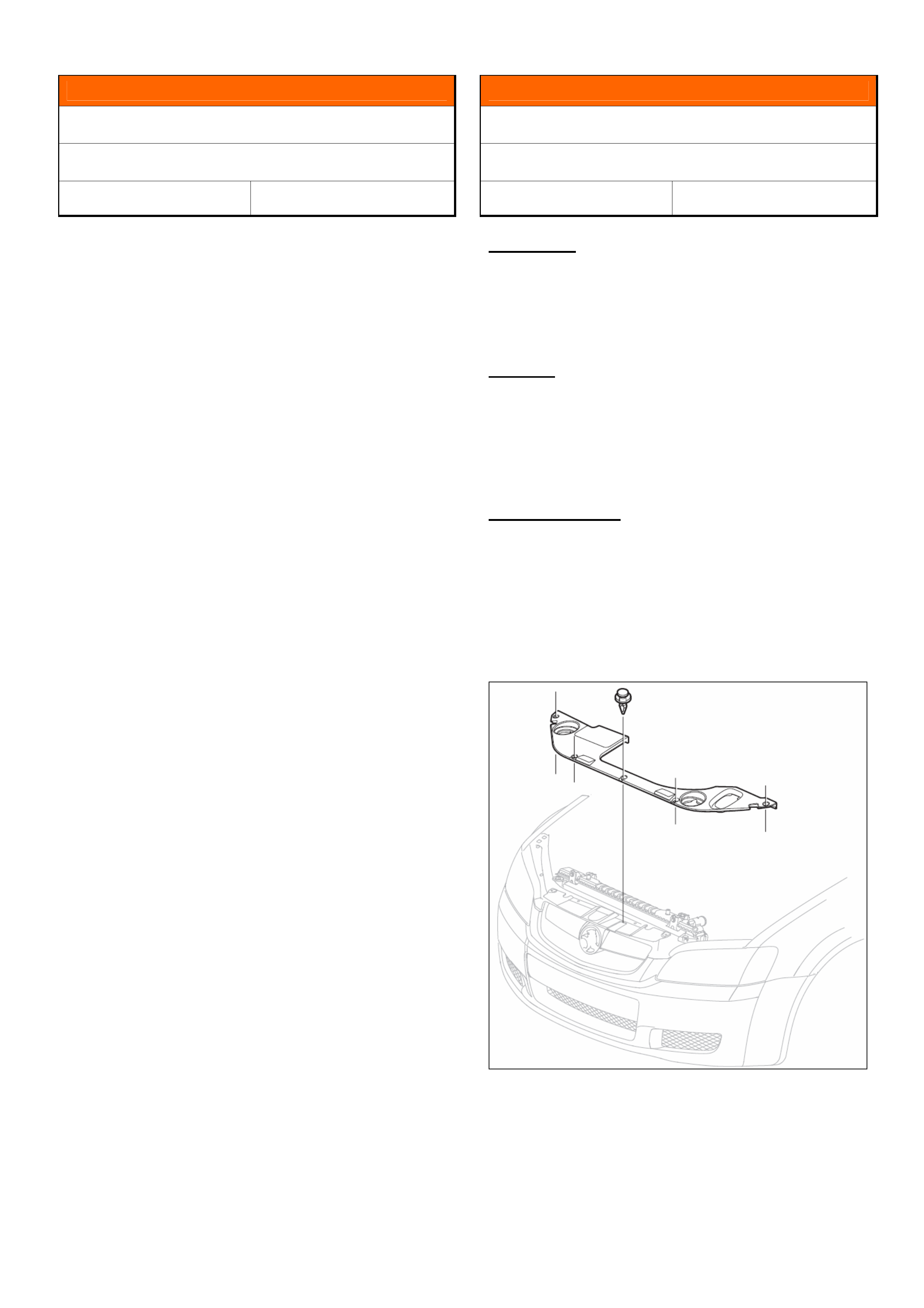
HOLDEN SERVICE TECHLINES__________________________________________________________________________ SEPTEMBER, 2006
5
INFORMATION
Interior Lamp Operation
VE, WM
Group 12 Ref. No. TL1174 – 0608
Dealer staff need to be aware that on VE/WM models
the interior dome lamp functionality is ambient light
dependant unless overridden by the switch within the
roof console. Its operation is driven by the BCM, with
input from the solar sensor fitted to the top centre of
the instrument panel.
Therefore, if a customer complains that the interior
lights do not work; ensure they are aware of the
operation as stated in the owner handbook. DO NOT
replace the BCM for this complaint.
To test the functionality of the dome lamp, place a rag
or thin book over the sensor and lock/unlock the
vehicle with the remote key or open a door. The lamp
should work because the sensor’s capability of
detecting light has been diminished.
Please pass this information to your dealership’s front-
line staff to avoid unnecessary customer complaints
and/or bookings.
INFORMATION
Radiator Shroud Usage
VE with P.O. LE0 V6 Engine
Group 6K Ref. No. TL1161 - 0608
CONDITION
PIR’s have been received advising that Technicians
believe radiator shrouds, on vehicles with base level
V6 engine P.O. (Production Option) LE0, have not
been fitted in production.
REASON
Vehicles with base level V6 engine do NOT have a
radiator shroud fitted.
Only vehicles with premium V6 (P.O. LY7) and V8 (P.O.
L89/LS2) engines have radiator shrouds fitted.
SERVICE ACTION
Do NOT fit radiator shrouds to vehicles built with P.O.
LE0 V6 engine.
This is not an error in build specification – and
cannot be claimed under warranty.
For reference – the shroud picture is shown bel ow:

HOLDEN SERVICE TECHLINES__________________________________________________________________________ SEPTEMBER, 2006
6
INFORMATION
A/T Fluid Availability
Daewoo Matiz with A/T
Group 7B Ref. No. TL1137 – 0608
CONDITION
There have been difficulties in obtaining the specified
ATF (Auto. Trans. Fluid) for the small number of Matiz
auto trans equipped vehicl es in Australia.
CAUSE
Previously released Daewoo bulletins advised the use
of an ATF specification that is no longer available in
Australia.
FLUID AVAILABILITY
ATF for these vehicles is now available from HSPO.
Part No.: Description Qty:
93742563 Auto Trans Fluid – 1 Litre 1
INFORMATION
P/S Fluid Usage
TK Barina
Group 9 Ref. No. TL1180 - 0608
CONDITION
Technician concern has been raised about correct fluid
to be used in power steering system, as the fluid colour
in early build vehicles is a “straw” colour, where the
specified fluid is Dexron® III (normally red/pink).
CAUSE
Early build vehicles were filled with Dexron® III fluid
with no red dye included.
SERVICE ACTION
It is not necessary to replace any power steering fluid
that is not “red/pink”.
Use Dexron® III for any power steering fluid
replacement during repairs or for any top-ups required.
SERVICE FIX
Fuel Gauge Drops To Empty & DTC P0460
Sets In The Engine ECU
VZ, WL, all with HFV6 MY06
Group 12 Ref. No. TL1164 - 0608
CONDITION
Customers may advise their fuel gauge drops to empty
and the low fuel light comes on or “Fuel Gauge Error”
message displayed in instrument cluster.
DTC P0460 "Fuel Level Sender range / performance"
sets in the engine ECU
CORRECTION – Vehicles In Service
On any vehicle with the above condition reprogram the
engine ECU as per the standard SPS process using
Tech 2 and TIS 2000 version 74 or later.
WARRANTY CLAIM INFORMATION
Use standard Labour Times found in the Warranty
Information section of the current PV SIP disc.
INFORMATION
Rear Drive Shaft (LH & RH) Attaching Bolt &
Retaining Plate Revisions
VY Series, All with IRS
Group 4 Ref. No. TL1183 - 0608
Rear driveshaft to trunnion/differential flange attaching
bolts and retaining plates have been superseded in
HSPO to use existing VZ parts - 92180093 Bolt , and
92180086 Retaining Plate.
This revision also requires a revised bolt torque - to the
VZ specification (50Nm + 90 deg turn a ngle).
Current VY SIP information is to be revised in the next
issue to advise:
- Bolt replacement is mandatory;
- Torque specification revised to current VZ torque
specification - 50Nm + 90 deg turn angle.
Both bolts (and retaining plates where n ecessary) need
to be replaced with the latest type whenever the bolts
are removed for any reason.

HOLDEN SERVICE TECHLINES__________________________________________________________________________ SEPTEMBER, 2006
7
INFORMATION
Introduction Of Extended-Life Anti-Freeze
Engine Coolant
TK Barina, JF Viva
Group 6K Ref. No. TL1179 - 0608
The cooling system in the above models is now filled
with extended life anti-freeze coolant, conforming to
Holden specification number GM 6277M.
Vehicle Production Breakpoint
Extended-life anti-freeze coolant has been fitted to
vehicles from:
TK hatch - KL1TJ23737B68561 6 May 2, 2006
TK Sed - KL1TJ53777B029209 May 2, 2006
JF Viva - KL1NA196J7K485172 July 3, 2006
This new coolant is designed to last in the vehicle for
five years or 240,000 km, whichever occurs first.
The new coolant colo r is orange/red.
If the cooling system needs to be topped up or
replaced, use a mixture of 50 percent clean water and
50 percent extended life coolant conforming to GM
6277M.
NOTE: Other coolants may be used provided they
comply with the Holden specification number GM
6277M.
WARNING.
• Never mix different types of coolant.
• Using other than the specified coolant may cause
premature engine, heater core, or radiator
corrosion.
PARTS INFORMATION
Part No.: Description Qty
92145527 Coolant engine 5 Litre (G M
6277M) 1
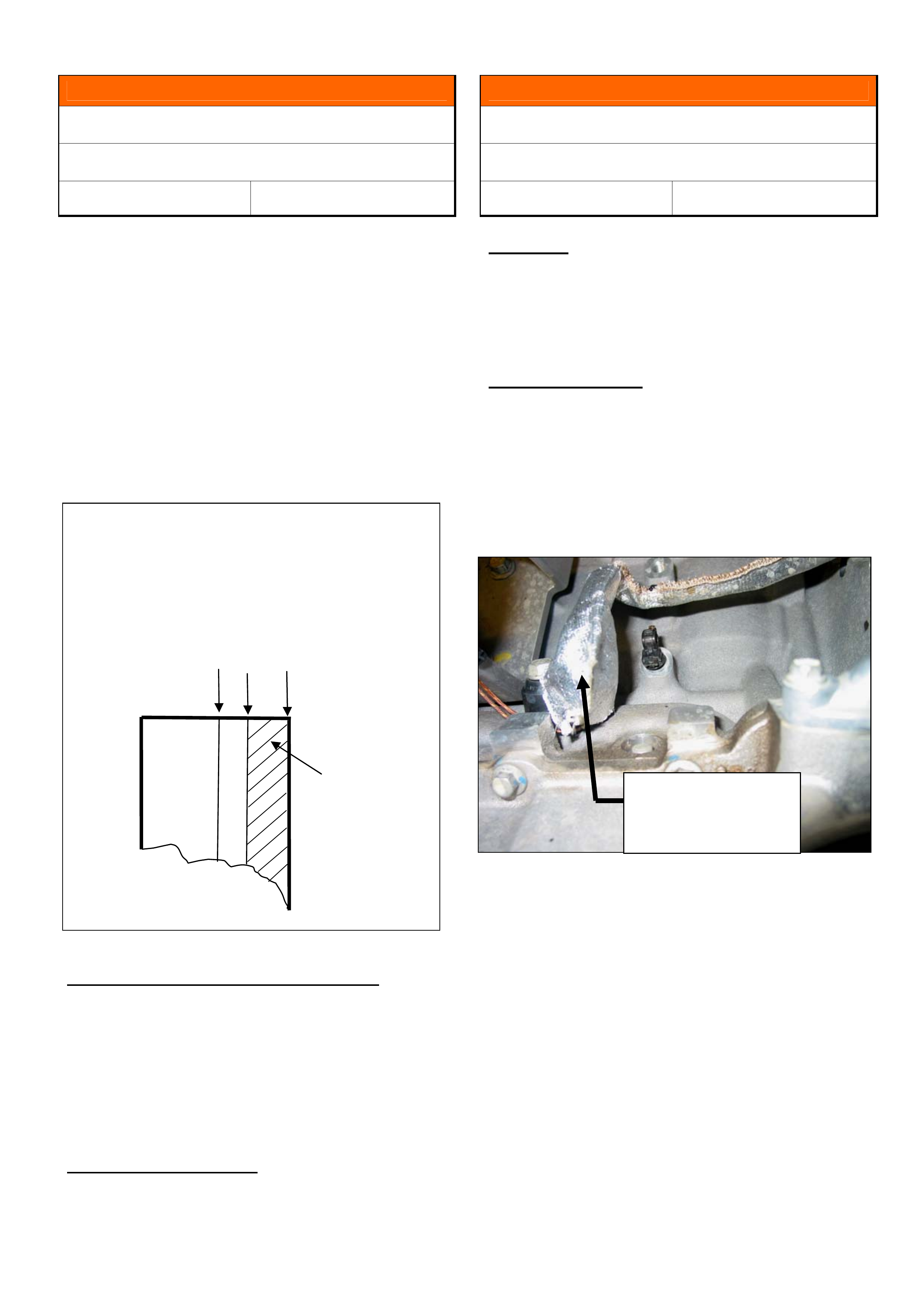
HOLDEN SERVICE TECHLINES__________________________________________________________________________ SEPTEMBER, 2006
8
INFORMATION
Brake Rotor Replacement Guidelines
ZC Vectra, TS & AH Astra, XC Barina
Group 5 Ref. No. TL1158 - 0608
To achieve maximum life of the brake rotors on the
above vehicles the following guidelines should be
observed in regard to brake rotor repla c ement.
TIS 2000 quotes three thickness dimensions for the
brake rotors:-
1. Thickness new.
2. Permissible remaining thickness after precision
turning.
3. Minimum thickness.
NOTE: This information is found in:- TIS2000 Service Information /
front wheel brake and rear wheel brake/ Technical Data.
If machining rotors & fitting new pads:
- the rotors can be machined down to the “permissible
remaining thickness after precision turning” and a new
set of pads can be installed.
Rotors should only be replaced if the “permissible
remaining thickness after precision turning” falls below
the dimension given in TIS2000.
If fitting new pads only:
- provided the rotor thickness is equal to/greater than
the “permissible remaining thickness after precision
turning,” a new set of pads can be in stalled.
INFORMATION
Knock Sensor Wiring Protection Precaution
VE, WM
Group 12 Ref. No.: TL1176 - 0608
Condition
Reflective hoods have been fitted to engine wiring
harnesses for the protection of V6 Crank Sensor and
V8 Knock sensor connectors from radiated exhaust
heat.
Service Precaution
If these hoods are removed for any reason, they
should be refitted to the original location to ensure that
the sensors are protected from heat radiated from the
exhaust or catalytic converters.
The photograph below shows a typical protective hood
installation – where the hood protects the wiring
harness connector from radiated heat.
Minimum 3.
Thickness after
precision turning 2.
New 1.
Do not replace rotors
if final thickness after
machining is within
cross hatched region
Heat reflective
hood fitted over
connector