
2006 SERVICE TECHLINES
© 2006 GM Holden LTD. A.B.N. 84 006 893 232
Service Department
A “Holden” Product
BRISBANE SYDNEY MELBOURNE ADELAIDE PERTH
For the latest and/or any missing Techline bulletins,
please refer to Holden Lionheart

HOLDEN SERVICE TECHLINES___________________________________________________________________________FEBRUARY, 2006
4
Holden Techlines are written to inform technicians of conditions that may occur on some vehicles, and to provide information that could assist in the
proper service fix of a vehicle. If a condition is described, do not assume the service fix applies to a vehicle or that the vehicle will have that condition.
INFORMATION
Introduction of DVD for TIS 2000
All
Group OB Ref. No. TL1025A - 0601
This Techline supercedes the previous one in Issue 10,
Nov, 2005. It is revised by adding a note on setup of the
DVD drive.
From January 2006 the previous CD-ROMs for TIS
2000 will be replaced by a DVD.
The major growth in data in recent years has made
this change necessary.
Please ensure that your TIS 2000 PC has a DVD
drive by 1.1.2006 at the latest.
Advantages of changing to DVD.
• The previous data set of 4 CDs will be replaced by
one DVD
• Simpler updates, without having to change the CD
several times
• Quicker updates
• Improved quality graphics
• Use of digital photos
• Conventional CD-ROMs can also be read by DVD
drives
Important Note - DVD Setup
To guarantee a smooth update for TIS 2000, it is
essential that any new DVD drive to be used for TIS
2000 DVD’s is allocated to the letter previously used
by the CD drive. If this is not done, TIS 2000 must be
uninstalled and the DVD drive set up as a new
installation.
For more information refer to Dealer Letter 25/05 and
the TIS 2000 Newsletter available on TIS 2000 CD66.
INFORMATION
Tag Number Identification Plate
RA Rodeo
Group OB Ref. No. TL1040 - 0601
On imported vehicles the Tag Identification Plate is
normally fitted to the radiator support panel at Port Of
Entry.
This plate is no longer fitted to the following imported
models:
RA Rodeo.
Tag plate no longer fitted as from Friday 21/10/05.
JF Viva and TK Barina.
Tag plate not fitted commencing from model
introduction.
NOTE: The 17 digit Vehicle Identification Number
(ISOVIN) remains as the main identification number
for all vehicles.

HOLDEN SERVICE TECHLINES___________________________________________________________________________FEBRUARY, 2006
6
Holden Techlines are written to inform technicians of conditions that may occur on some vehicles, and to provide information that could assist in the
proper service fix of a vehicle. If a condition is described, do not assume the service fix applies to a vehicle or that the vehicle will have that condition.
INFORMATION
Electronic Odometer Programming
RA Rodeo,
UBS Jackaroo MY1998 onwards,
UES Frontera MY2001 onwards
Group 12 Ref. No.TL0481A-0601
This Techline supercedes the previous one in Issue 5,
2003. It is revised by adding TK & JF models.
When a replacement instrument cluster is installed
into one of the above models it is a requirement to
program the odometer to the value of the one
removed.
If your Service Department does not know of any
instrument repairers who are capable of performing
this operation on the above models, below are some
contacts of instrument repairers currently being used
by other Dealers.
Victoria
Automotive Instrument Repairs
59 C Glenvale Crescent,
Mulgrave, Victoria 3170
Phone (03) 9561 2366
Fax (03) 9561 9134
NSW
Macarthur Instruments
P.O. Box 3016
Narellan Delivery Centre, NSW, 2567
fax (02) 4659 7294
Mobile (0416) 241 903
QLD
Future Auto Instruments
113 Turpin Rd,
Labrador, QLD 4215
Mobile (0414) 518 766
New Zealand
Robinson Instruments
19 Fale Street
Freeman's Bay
Auckland
Phone (09) 3771565
Fax (09) 3580573

HOLDEN SERVICE TECHLINES___________________________________________________________________________FEBRUARY, 2006
13
Holden Techlines are written to inform technicians of conditions that may occur on some vehicles, and to provide information that could assist in the
proper service fix of a vehicle. If a condition is described, do not assume the service fix applies to a vehicle or that the vehicle will have that condition.
INFORMATION
A/C Compressor Noise, Replacement
Guidelines
RA Rodeo
Group 2 Ref. No. TL1068 - 0601
A high rate of A/C compressors returned to REPAC for
noisy operation have been vehicle and bench tested
with No Fault Found.
Further investigation has found that if the A/C system
is over or undercharged, compressor noise will
become evident. The tests indicate that if the charge
level was as low as 600 grams or as high as 800
grams, noise was introduced to the A/C system that
could result in customer complaint.
Prior to replacing an A/C compressor the following
steps must be followed:
• Check that the A/C system is fitted as per the
fitting instruction ensuring that all plumbing is
routed correctly and not contacting body or
engine components.
• Recharge the A/C system with the correct
weight of gas (measure the gas removed and
note in the warranty claim). If the gas charge
was low then check for leaks.
If the compressor is going to be replaced the
warranty claim 3C’s must describe the exact
customer complaint, when the noise occurs
including operating environment and the type of
noise. This information will help to identify any
compressor problems and avoid chargebacks.
The following points should be observed when
replacing A/C system components:
• High and low side pressures should be
allowed to equalise prior to degassing.
• Fast gas recovery draws more oil from the
system. Initially the low side tap should be
opened gradually to slow the gas recovery rate
which reduces the amount of oil removed with
the gas.
• Spare parts are supplied dry (except
compressor) and an appropriate amount of oil
should be added when replacing components
(See table 1).
• When a compressor is replaced, an oil balance
test must be performed.
• Charging procedure is detailed in the fitting
instructions.
Table 1
Component Replaced Oil To Be Added To System
Evaporator 30mls
Condenser 30mls
Receiver Drier 15mls
Any Pipe 5mls
Compressor Oil Balance Required.
SERVICE FIX
Check Engine Light On – DTC P0502 Sets
RA Rodeo - 4 Cyl. Petrol Engine
Group 6C Ref. No. TL1073 - 0601
CONDITION
Check Engine Light (CEL) illuminates intermittently,
DTC P0502 is found during diagnosis.
CAUSE
Incomplete starting procedure - IE: cranking and not
holding key on long enough for engine to start – has
been defined as the most likely cause of the DTC
setting. The DTC only sets and illuminates the CEL
when this occurs on two consecutive ‘key on’ cycles,
thus the intermittent nature of CEL and code setting.
CORRECTION – Service
Summary: SPS vehicles using LCRV TIS 2000 CD 19
or later (delivered to Dealers in January, 2006).
On vehicles with the above complaint, reprogram the
engine electronic control unit via the standard Service
Programming System using LCRV TIS 2000 CD No.
19 or later.
WARRANTY CLAIM INFORMATION
Use Existing Labour Times information in Warranty
Information section of current LCV SIP CD as follows:
Description Engine Diagnostic Trouble
Code P0502
Labour Op. No. J900502
Time ST
Failure Code K0057 Registers incorrectly

HOLDEN SERVICE TECHLINES______________________________________________________________________________MARCH, 2006
6
Holden Techlines are written to inform technicians of conditions that may occur on some vehicles, and to provide information that could assist in the
proper service fix of a vehicle. If a condition is described, do not assume the service fix applies to a vehicle or that the vehicle will have that condition.
DIAGNOSIS HINT
Whistle / Squeal Noise From Engine Turbo
Under Acceleration
RA RODEO Diesel 4JH1
Group 6A Ref. No. TL1075 - 0602
PROBLEM DESCRIPTION
Owner may complain of whistle or squealing noise
from the engine when under acceleration. May also be
referred to as loud Turbo Charger whistle noise
SERVICE RECTIFICATION
Whistle and squealing noises can be generated by air
leaks in the intake or exhaust system on a turbo
charged engine. The noise can be generated when
high pressure air or exhaust gas is escaping from a
leaking gasket or hose clamp.
If an RA Rodeo 4JH1 diesel is presented with the
above complaint, the following checks should be
performed
• Ensure that all intake hoses, ducting and clamps
are tight and leak free.
• Check the exhaust system (manifold & gaskets) for
signs of leaking.
• Check the EGR crossover pipe (4) and associated
gaskets (5 & 6) for leaking as shown in picture
below.
DO NOT REPLACE TURBO CHARGERS FOR THE
ABOVE COMPLAINT
Contact TAS if the above checks fail to resolve the
complaint.
6
INFORMATION
Accessory Cruise Control Inoperative After
Fitment
RA Rodeo with 3.6 HFV6
(GROUP 12) TL1086-0602
PROBLEM DESCRIPTION
Dealers may find that after fitting accessory cruise
control to an RA Rodeo “HFV6 engine,” the cruise
control may not operate.
The PIM will only “Auto Detect” that the cruise control
switch has been fitted after a “Power Down” situation.
SERVICE RECTIFICATION
Dealers are reminded that the battery negative cable
must be disconnected during fitment of the cruise
control kit. Upon reconnection, the PIM should
automatically detect that cruise control is now fitted
and will function correctly.
If Cruise Control has been fitted without disconnecting
the battery and is not operating, disconnect the
negative battery cable for at least 30 seconds. Then
reconnect the cable and check for correct cruise
operation

HOLDEN SERVICE TECHLINES______________________________________________________________________________MARCH, 2006
14
Holden Techlines are written to inform technicians of conditions that may occur on some vehicles, and to provide information that could assist in the
proper service fix of a vehicle. If a condition is described, do not assume the service fix applies to a vehicle or that the vehicle will have that condition.
INFORMATION
Holden Contacts and procedures
All
Group OB Ref. No. TL0679B-0602
This Techline supercedes the previous one (TL0679A-0501) in
Issue 1, Feb 2005. It contains UPDATED information.
This techline summarises some of the Holden contact
procedures and gives a quick reference guide for
contact numbers.
Security information.
To obtain security information for both Passenger and
LCRV vehicles the first step is to check the New Online
Warranty system (NOW). If the information is
unavailable on NOW then a completed security
information request form must be faxed through to the
Vehicle Security Information Centre, as security
information cannot be given out by phone. Please note
that security information requests are processed by the
Vehicle Security Information Centre and not TAS.
To ensure you have the latest security information
request form always refer to Service Forms in the
Service Bulletin section of the Holden Lionheart Portal.
Fax completed forms to the Vehicle Security
Information Centre on fax 03-96472865.
There can be up to a 4-hour turn around on requests,
however if the information needs to be obtained from
overseas, it may take up to 24 hrs. Do not phone the
security information department unless you have not
received a response in the normal turn around time.
For further information please refer to ADL 42/05.
Accessories and parts inquiries
If any information or assistance is required in regards
to Microcat, part numbers, Holden accessories or if
you need to contact HSPO Customer Assistance,
please refer to the Holden Help section in Microcat.
Warranty Authorisation and enquiries
Warranty can only be authorised by your Aftersales
District Manager. Labour times information is available
on SIP or from the warranty department. For any other
warranty inquiries please contact Warranty
Administration.
TAS
Technical Assistance Service (TAS) is a service
provided by Holden to assist Holden Dealers in
problem resolution.
Contact to TAS must be made by a Nominated Contact
as outlined in Section 5 of the TAS procedures
manual. All techlines, dealer letters and service
information must be checked prior to contacting TAS.
The Nominated Contact must not contact TAS until
he/she has been fully involved with the faulting vehicle
and all Dealer expertise has been exhausted.
Problems should be escalated through the Dealership
to the senior technician/foreman before contacting
TAS.
TAS cases must be updated or closed within 30 days
unless a Dealer is waiting on a service fix to be
provided. It is the Dealers responsibility to update
cases. All cases should be recorded in the TAS
procedures manual, which should be referred to prior
to contacting TAS. Please note that an electronic copy
of the TAS procedures manual is also available on
passenger SIP.
Under no circumstances are TAS or other Holden
contact details to be supplied to customers or
independent repairers. TAS is a service restricted to
assisting Holden Dealer service departments.
Quick reference contact numbers
Autostrada Ph 1800 634 343
Air International Ph 1800 673 716
Australian Arrow Ph 03 9785 0792
Blaupunkt Ph 1300 307 036
Bosch Technical Assistance Ph 1800 025 462
Clarion Ph 1300 730 730
Fax 03 9551 0377
Customer Assistance Ph 1800 033 349
Dana Ph 02 9892 9237
Ph 02 9892 9343
Fax 02 9892 9310
www.spiceraxle.com.au
HBD DVD support (Delphi) Ph 03 8558 8313
Eurovox Ph 03 9237 0800
Fujitsu Ten Ph 03 9646 6008
Holden Assist Ph 1300 880 088
Hollandia/Webasto sunroof Ph 02 9540 4811
Fax 02 9540 4316
HSV Ph 03 9265 9500
Impco Ph 03 9584 5644
Infomedia (SIP, Partfinder) Ph 1800 810 103
Lumen Ph 03 8787 1000
Panasonic Ph 02 9986 7635
PBR Diagnostic assistance Ph 1800 468 727
Petro-Ject Ph 02 9890 5701
Ph 02 9890 5244
Philips/Siemens-VDO Ph 1800 335 282
Salmat Ph 03 9358 2900
Security Information Ph 03 9647 2001
Fax 03 9647 2865
SPX Australia Ph 03 9544 6222
TAS Ph 1800 033 417
Fax 03 9647 2495
Email [email protected]
Triple M Ph 1800 773 030
Warranty Ph 1800 033 487
HOLDEN SERVICE TECHLINES______________________________________________________________________________MARCH, 2006
15
Holden Techlines are written to inform technicians of conditions that may occur on some vehicles, and to provide information that could assist in the
proper service fix of a vehicle. If a condition is described, do not assume the service fix applies to a vehicle or that the vehicle will have that condition.
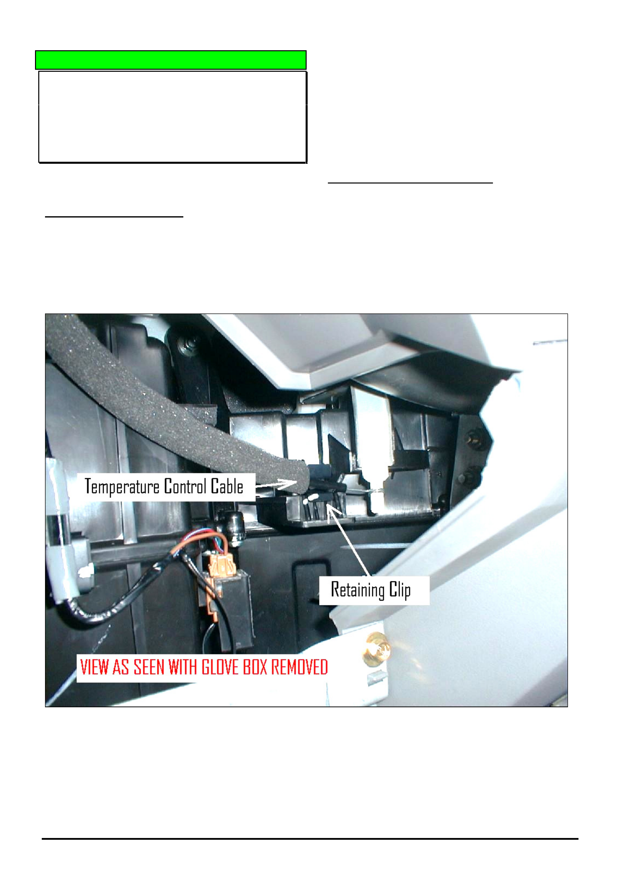
DIAGNOSIS HINT
HVAC Temperature Control Not Working – Air
Mix Cable Incorrectly Installed
RA Rodeo
(GROUP 2) TL0587A-0602
This Techline is REPEATED (from Issue 11/2003) as this
problem is still being reported from the field.
PROBLEM DESCRIPTION
There have been reports of the HVAC temperature
control (air mix dial) not working.
Investigation of complaint vehicles shows this problem
is due to the air mix cable not being held in the
retaining clip. This results in the outer cable moving,
which in turn causes the inner cable to dislodge from
the air mix door control lever.
In most cases, the cause of the above problem is the
cables have not been placed correctly into the
retaining clips when air conditioning has been originally
fitted to the vehicle.
SERVICE RECOMMENDATION
When installing air conditioning (or re-installing the
cable for any reason) it is important to pay special
attention to the correct installation of the air mix cable.
After installing the cable in the retaining clip, ensure
the full range of hot/cold adjustment can be achieved
with the control dial.
Figure 1. Shows Temperature control cable correctly retained in clip on side of HVAC case.

HOLDEN SERVICE TECHLINES________________________________________________________________________________APRIL, 2006
6
Holden Techlines are written to inform technicians of conditions that may occur on some vehicles, and to provide information that could assist in the
proper service fix of a vehicle. If a condition is described, do not assume the service fix applies to a vehicle or that the vehicle will have that condition.
DIAGNOSIS HINT
TECH 2 Usage
RA RODEO – HFV6
(GROUP OB) TL1100-0603
Some technicians are encountering a problem when
using Tech 2 on the above model where it keeps
returning to the base menu’s when this is not
commanded.
When navigating the menu’s on Tech 2, it is vital that
the “CONFIRM” “softkey” is used when Tech 2
prompts this input.
DO NOT use the “ENTER” key instead of the
“CONFIRM” key.
SERVICE FIX
SRS Light On DTC B0022 or B0016 Squib
Circuit Low Resistance
RA Rodeo
Group 12 Ref. No. TL1060 - 0603
CONDITION
Customers may advise the SRS (air bag) light
illuminates.
When Tech 2 is connected, DTC B0022 Drivers Squib
Circuit Low Resistance and/or B0016 Passengers
Squib Circuit Low Resistance codes set in the airbag
module.
CAUSE
This condition may be caused by a poorly formed SDM
connector causing the shorting pins not to disengage.
CORRECTION – Production
A revised SDM has been fitted in production from the
following breakpoint
ISOVIN: Built Date:
MPATFR77H6H525256 29/11/05
CORRECTION – Service
1. Confirm the above DTC’s are set (as ether current
or history).
2. Perform a visual inspection of the SRS harness to
ensure no obvious circuit damage.
3. Replace the SDM with the revised part as per the
standard LCV SIP procedure.
4. Using Tech 2, clear DTC’s in the SDM.
PARTS INFORMATION
Part No.: Description Qty:
8980326260 Revised SDM 1
WARRANTY CLAIM INFORMATION
.
Use Labour Times information in Warranty Information
section of current LCV SIP CD
HOLDEN SERVICE TECHLINES________________________________________________________________________________APRIL, 2006
10
Holden Techlines are written to inform technicians of conditions that may occur on some vehicles, and to provide information that could assist in the
proper service fix of a vehicle. If a condition is described, do not assume the service fix applies to a vehicle or that the vehicle will have that condition.
INFORMATION
Searching for Service Information on Holden Dealer Portal - “Lionheart”
(GROUP OB) TL0921A-0603
( This Techline supercedes the previous one in Issue 5, June 2005. It is UPDATED with the latest procedure. )
This Techline describes how to find the following Service Information on the Holden Dealer Portal - “Lionheart”.
• Service Techlines
• All Dealer Letters
• Campaign Bulletins
• Field reworks
• Warranty Processing
• Special Warranty Component Replacements
• Service Forms.
PROCEDURE.
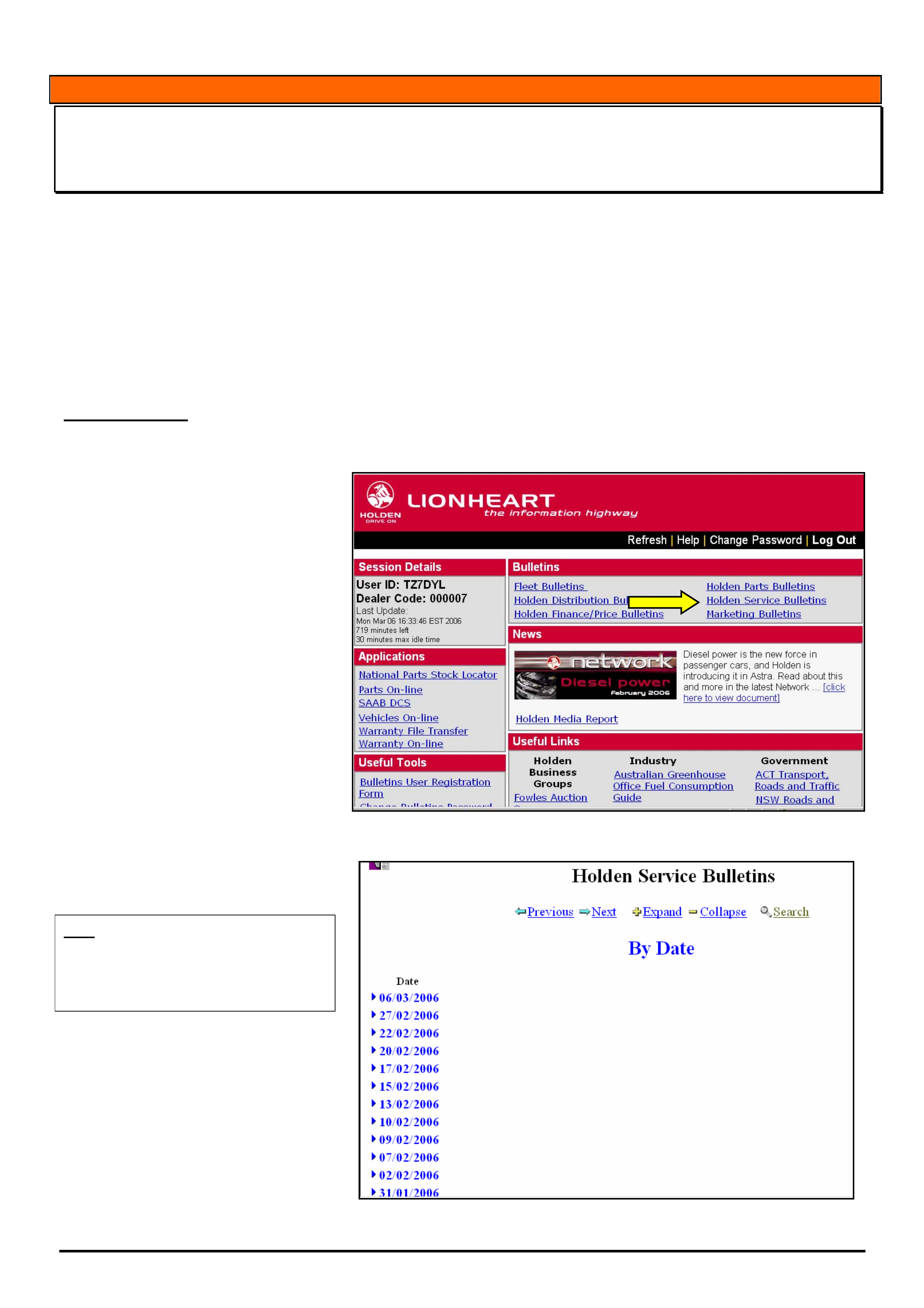
When you logon to the Holden Portal the Lionheart Home page will appear as shown in Figure 1.
Now select “Holden Service Bulletins”
as indicated by yellow arrow.
.
Figure 1
The next screen to appear is shown in
Figure 2.
HINT: This screen should be thought of as
an email inbox.
You should check this screen everyday to
view the latest information issued by
Holden Service Department.
The date at the top of the list is when
the newest bulletins were posted onto
Lionheart. In the example in Figure 2
this date is 06/03/2006.
Figure 2.
HOLDEN SERVICE TECHLINES________________________________________________________________________________APRIL, 2006
11
Holden Techlines are written to inform technicians of conditions that may occur on some vehicles, and to provide information that could assist in the
proper service fix of a vehicle. If a condition is described, do not assume the service fix applies to a vehicle or that the vehicle will have that condition.
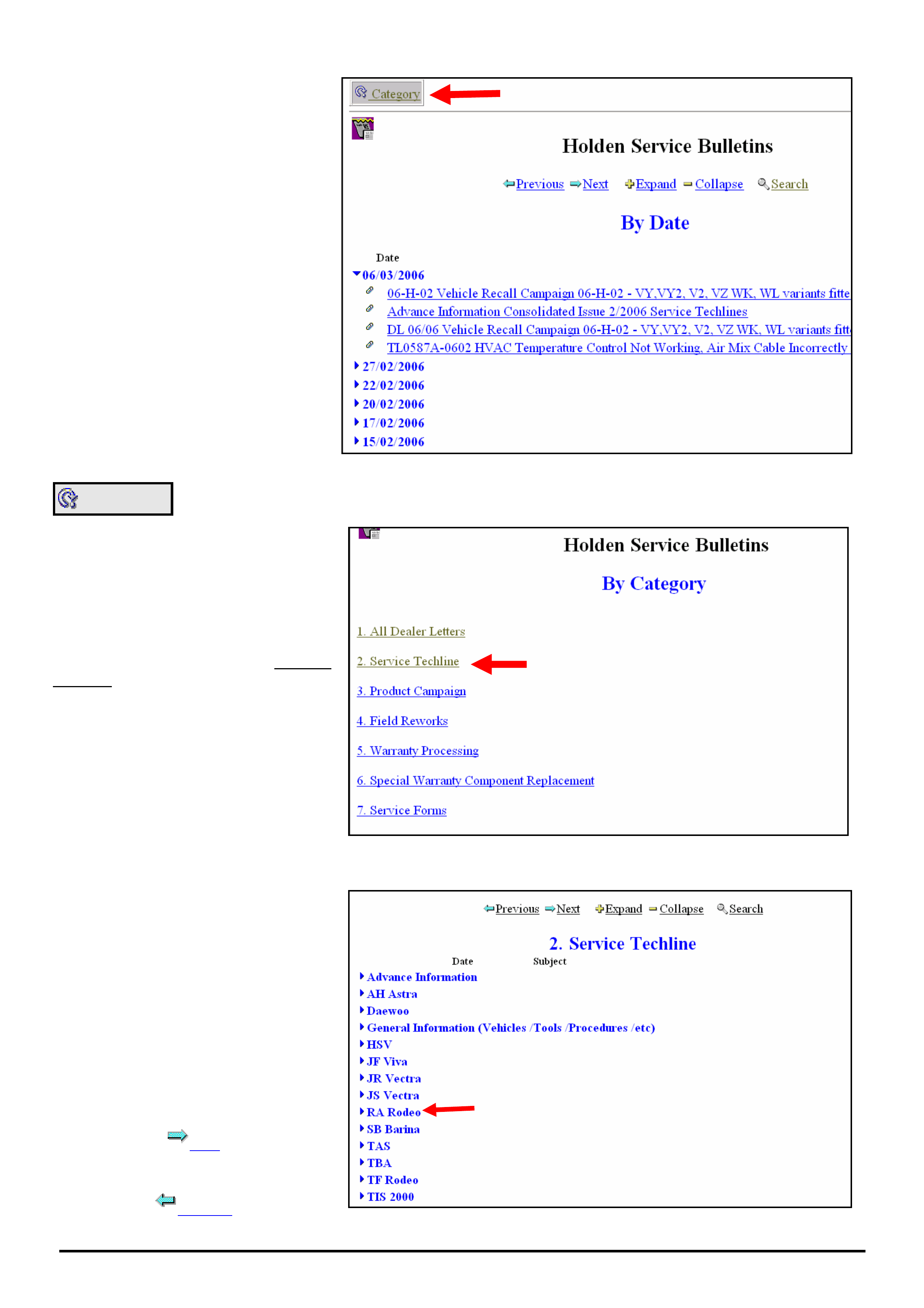
To view the bulletins for the 06/03/2006,
click on the “►” symbol next to the date
and a list of bulletins will appear as
shown in Figure 3.
To view any bulletin click on it.
Figure 3.
Category
If you select the “Category” button as
indicated by the red arrow in Figure 3
the screen shown in Figure 4 will
appear.
Now select the category you want.
As an example, select “Service
Techline”
The next screen to appear is shown in
Figure 5.
Figure 4
From this screen you select the model
you are interested in.
For example, click on the “►” next to
RA Rodeo
The next screen to appear is shown in
Figure 6.
NOTE: To view the full list of models
you will need to turn over to the next
page by clicking on the “next” arrow at
the top or bottom of the screen
Next
To go back a screen, press “previous”
Previous
Figure 5
HOLDEN SERVICE TECHLINES________________________________________________________________________________APRIL, 2006
12
Holden Techlines are written to inform technicians of conditions that may occur on some vehicles, and to provide information that could assist in the
proper service fix of a vehicle. If a condition is described, do not assume the service fix applies to a vehicle or that the vehicle will have that condition.
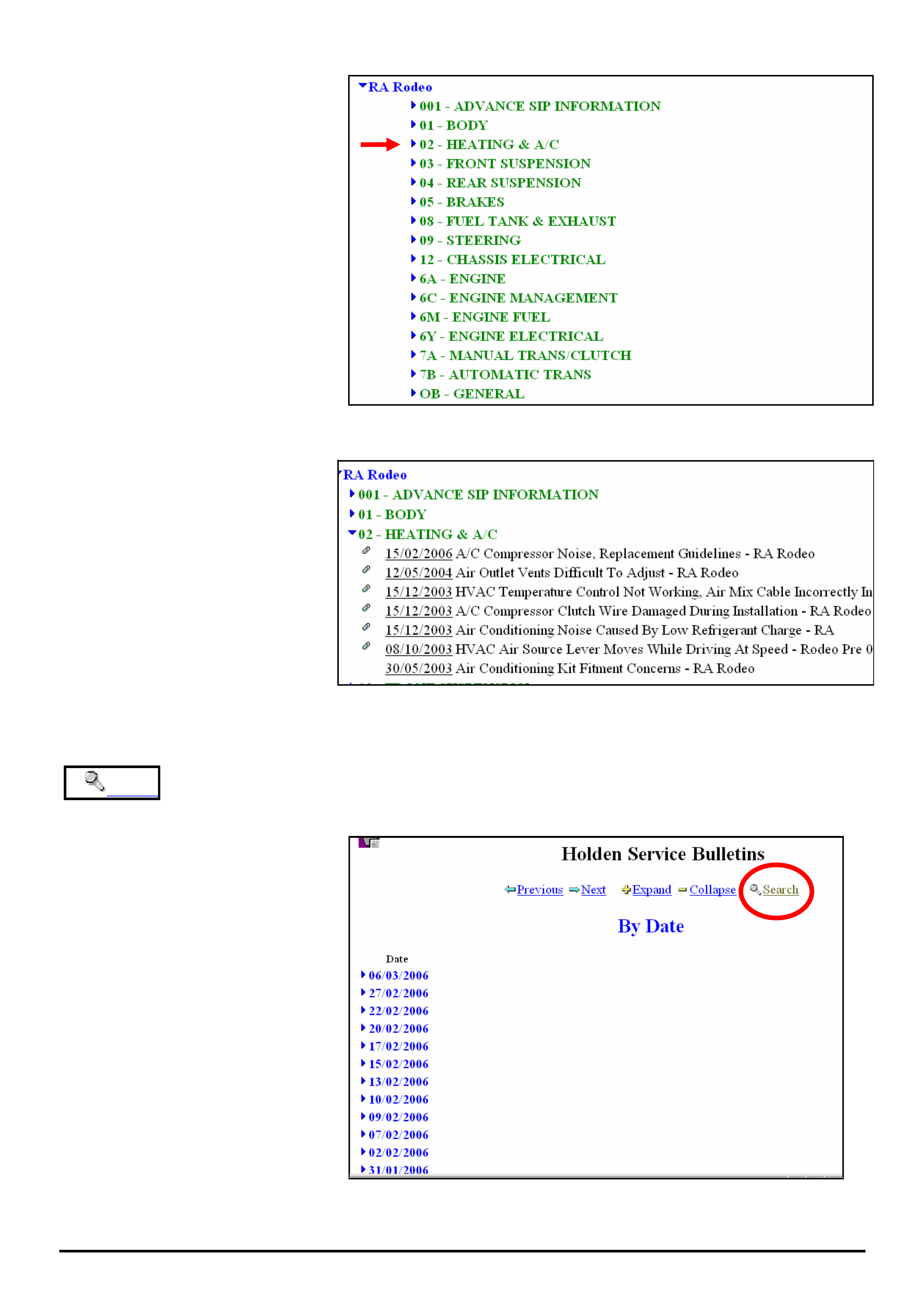
Now select the Group you are interested
in.
Example - select 02-HEATING & A/C
The next screen to appear is shown in
Figure 7.
Figure 6.
Now look through the list of Techlines
to find the one you are interested in.
NOTE: Techlines are arranged in
order of date with the newest at top of
list.
Figure 7.
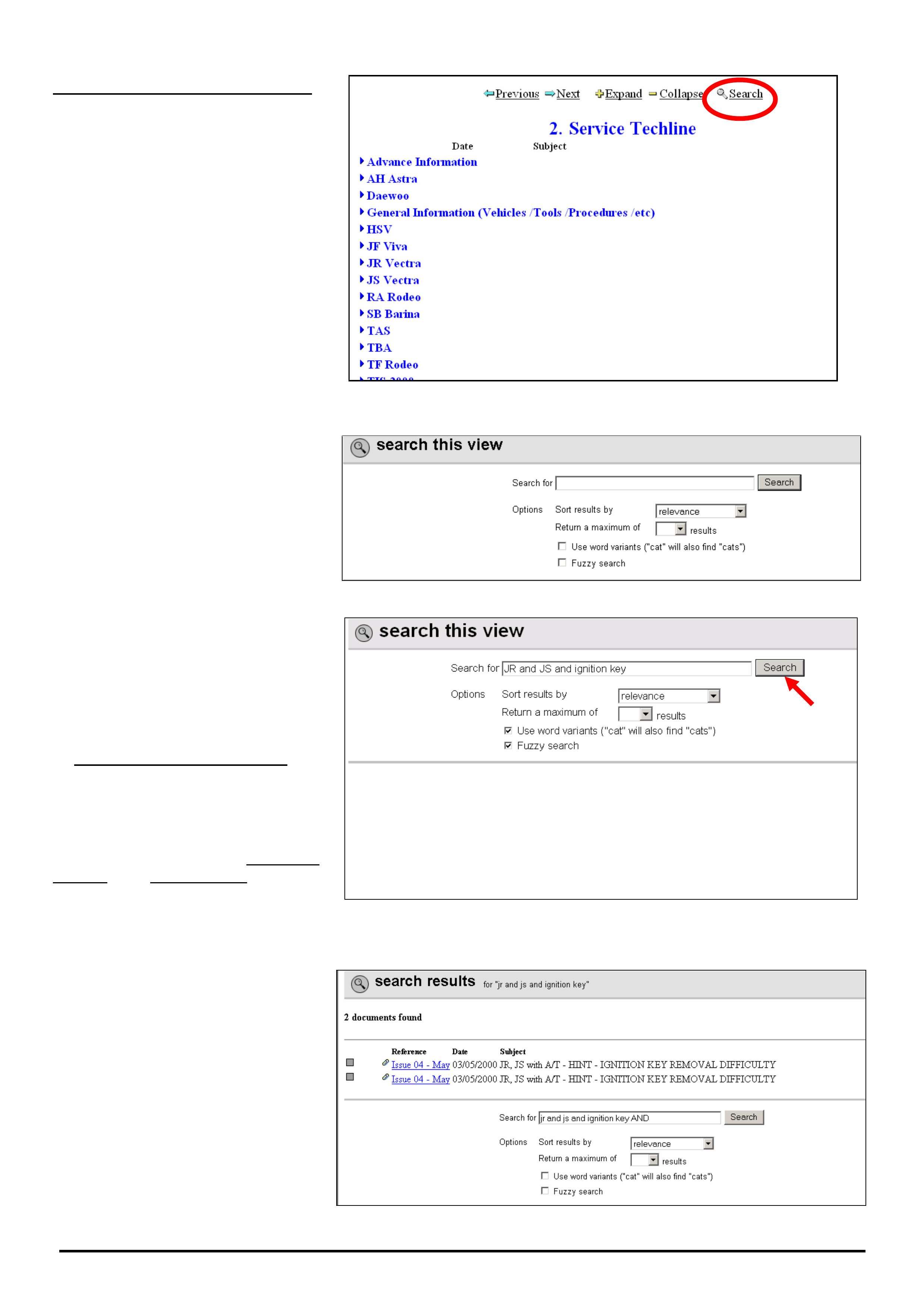
Search USING THE SEARCH METHOD TO FIND INFORMATION ON LIONHEART
If you select the SEARCH function
from the screen in Figure 8 it will
search through all the Service
Information Categories as follows:
• Service Techlines
• All Dealer Letters
• Campaign Bulletins
• Field reworks
• Warranty Processing
• Special Warranty Component
Replacements
• Service Forms.
To shorten the search process, select
the SEARCH function only after you
are in the particular category you are
interested in.
Following, is a description of how to
search for Service Techlines.
Figure 8
HOLDEN SERVICE TECHLINES________________________________________________________________________________APRIL, 2006
13
Holden Techlines are written to inform technicians of conditions that may occur on some vehicles, and to provide information that could assist in the
proper service fix of a vehicle. If a condition is described, do not assume the service fix applies to a vehicle or that the vehicle will have that condition.
Searching for Service Techlines
From the screen shown in Figure 9
click on the “Search” key. This will
bring up the screen shown in Figure
10.
Figure 9
This is the search screen used for
entering “keywords” to search for.
It is important to enter the right words
here in order to find what your looking
for.
Figure 10
As an example (Figure 11) try
searching for Techlines related to JR
& JS Vectra Ignition Barrel
Jamming.
In the top window, type in the following
“search string” exactly as shown.
“JR and JS and Ignition key”.
Don’t touch the next 2 boxes titled
“Sort results by” or,
“Return a maximum of”.
Tick the last 2 boxes i.e. Use Word
variants and Fuzzy search. Refer to
later explanations of these terms.
Now click the “Search” button. Shown
with the red arrow.
Figure 11
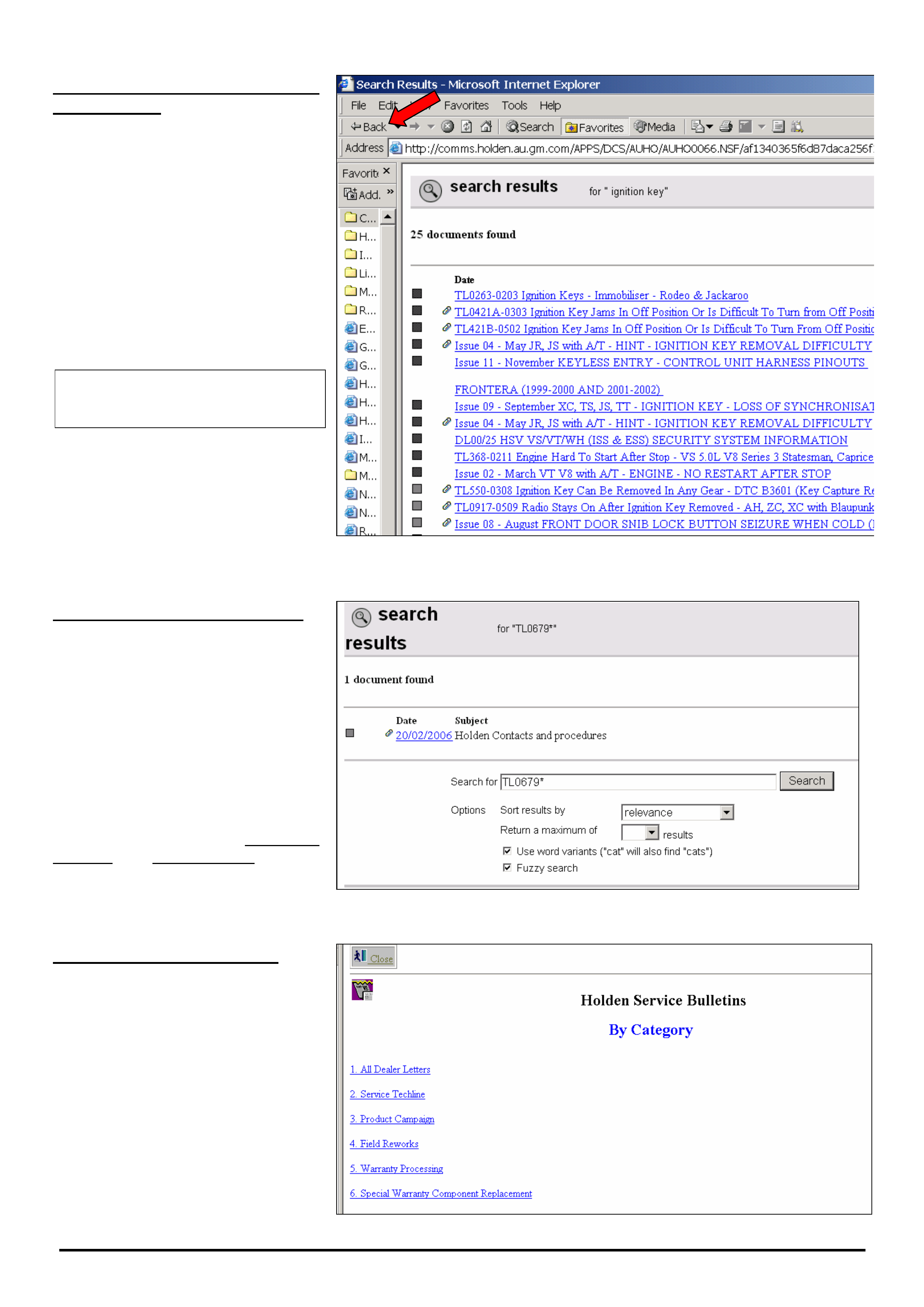
The search result is 2 documents as
shown in Figure 12.
Click on the hot-key section (in blue)
to view the techlines.
Figure 12.
HOLDEN SERVICE TECHLINES________________________________________________________________________________APRIL, 2006
14
Holden Techlines are written to inform technicians of conditions that may occur on some vehicles, and to provide information that could assist in the
proper service fix of a vehicle. If a condition is described, do not assume the service fix applies to a vehicle or that the vehicle will have that condition.
Notes on choosing “Keywords”
for searching
If we had only entered “ignition key”
without any model descriptor, this
would have located 25 items as shown
in Figure 13.
If we had only entered “ignition”, the
search would have located 86 items.
This demonstrates the importance of
selecting the right “keywords” to
search with so you don’t end up with
large numbers of items to read
through.
Rule of thumb: - The less
information in the “search window”
the more information comes back.
HINT: If at anytime you wish to go
back to the “Search” function press
the “Back” arrow in the top left side of
the toolbar. Refer red arrow in Figure
13.
Figure 13.
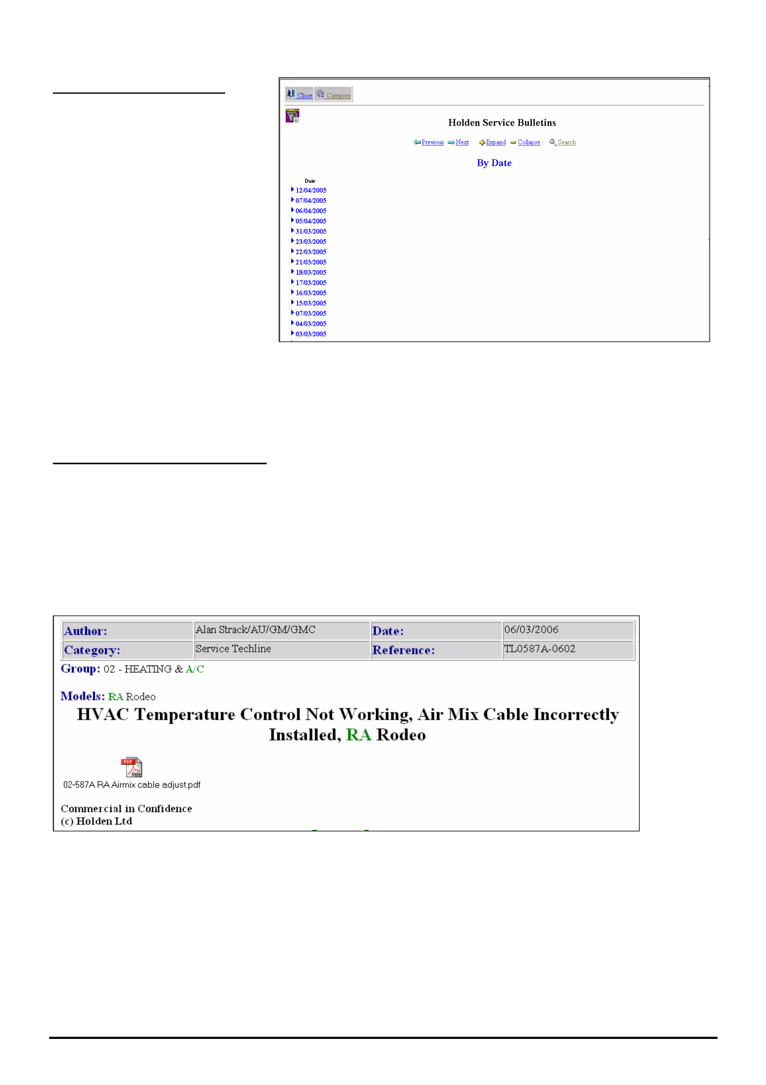
Searching by Techline Number
Use this procedure if you have an
existing techline and you want to
check to see if there is a later version
on Lionheart.
Example. - Search for the latest issue
of techline TL0679.
Type “TL0679*” in the search window
as shown in Figure 14.
Tick the last 2 boxes - “Use Word
variants” and “Fuzzy search”.
The latest version found will be
TL0679B-0602.
Figure 14
Searching Other Categories
The search procedure described
above for Service Techlines may also
be used for Dealer Letters, Campaign
Bulletin, Field rework, Warranty
Bulletin, etc. You must first select the
category you want from the Category
screen (Figure 15) before proceeding
with search.
Use the same procedure as that
described for a Service Techline.
HOLDEN SERVICE TECHLINES________________________________________________________________________________APRIL, 2006
15
Holden Techlines are written to inform technicians of conditions that may occur on some vehicles, and to provide information that could assist in the
proper service fix of a vehicle. If a condition is described, do not assume the service fix applies to a vehicle or that the vehicle will have that condition.
Figure 15.
Doing a “General” search.
To find ALL published information on
a particular subject, select “Search”
from screen shown in Figure16.
As an example, enter “Daewoo” in
the search field
This “search” will give you everything
that contains the word “Daewoo” .eg.
Dealer letters, Techlines, Recalls,
Warranty etc.
Figure 16
General Notes On Searching.
• If you perform a search and the results are not what you were looking for; to conduct another search, you will need
to hit the “← Back” arrow as shown in Figure 13. This will bring up the “active” search window. Delete the current
search keywords then enter some new keywords and press “search” again.
• The search engine cannot search any “attached” files for keywords. For example, in Figure 17, the search engine
will search through every word that actually appears on the screen as shown. It cannot search through the
attached file, viz “02-587A RA Airmix cable adjust.pdf”.
Figure 17
HOLDEN SERVICE TECHLINES________________________________________________________________________________APRIL, 2006
16
Holden Techlines are written to inform technicians of conditions that may occur on some vehicles, and to provide information that could assist in the
proper service fix of a vehicle. If a condition is described, do not assume the service fix applies to a vehicle or that the vehicle will have that condition.
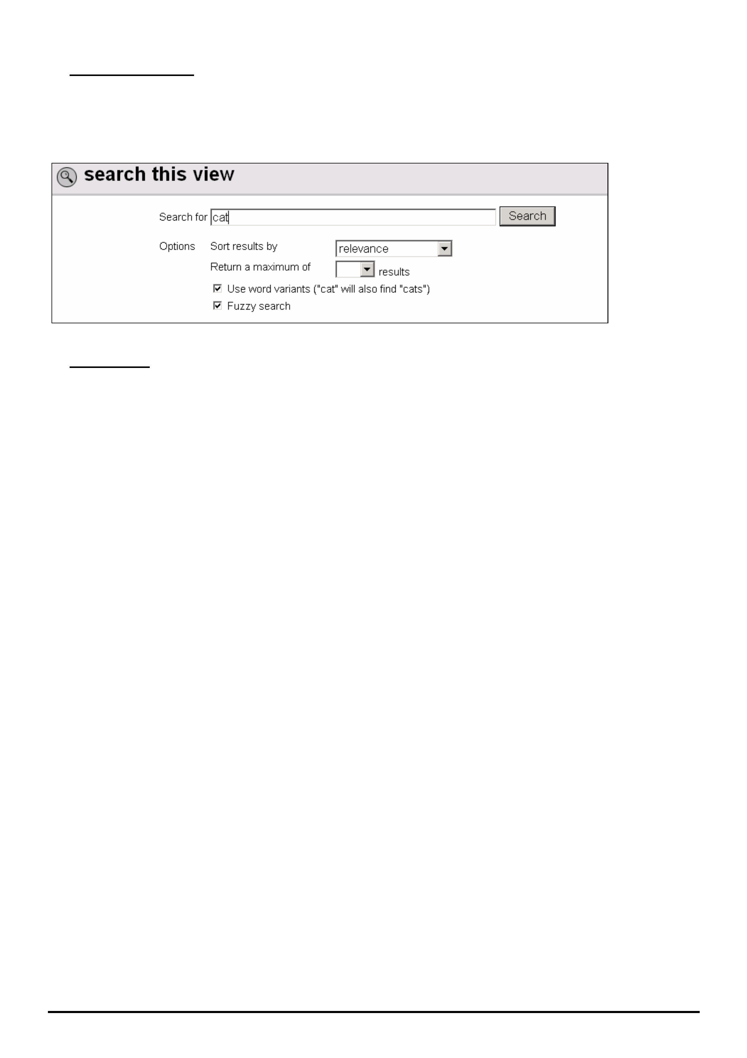
• “Use Word Variants”
If you tick this box in the search panel (refer Figure 18) and type in “cat” in the “Search For” window, the search
engine will find every word that has cat in it, eg. catalytic, category, cats, etc. This is useful if you cannot remember
the exact spelling of a word or you forget the “s” when the word is plural.
Figure 18.
• Fuzzy Search
EXAMPLE 1. - Search for techlines with DTC P0335 in the Subject title.
If you accidentally type in DTCP0335 without a space between C and P, and do a Fuzzy search, the search engine
will still bring up all techlines containing “DTC P0355”.
EXAMPLE 2. - Search for techlines containing 4JX1 in the subject title.
If you type in 4JX, a fuzzy search will still find all techlines with 4JX1 in the title.
NOTE: this feature doesn’t work if you forget to enter the first letter. In this example, doing a Fuzzy search on JX1 will
not find anything.

HOLDEN SERVICE TECHLINES_________________________________________________________________________________MAY, 2006
Holden Techlines are written to inform technicians of conditions that may occur on some vehicles, and to provide information that could assist in the
proper service fix of a vehicle. If a condition is described, do not assume the service fix applies to a vehicle or that the vehicle will have that condition.
INFORMATION
DTC P0532 Set After Fitting A/C
RA Rodeo with HFV6
Group 2 Ref. No. TL1111 - 0604
PROBLEM DESCRIPTION
DTC P0532 (Air Conditioner Pressure Low) is logged
in the ECM as either a Present or Not Present DTC
after fitting Air Conditioning.
SERVICE RECTIFICATION
Ensure that a DTC check is carried out after fitting,
servicing, or charging the Air Conditioning system.
It is quite normal for the DTC to log while the Air
Conditioner is being “charged”.
Once the DTC is “cleared” with Tech 2, any further
occurrence of the DTC needs to be addressed in the
normal manner. Refer to LCRV SIP and Strategy
based diagnostics.
DIAGNOSIS HINT
Check Engine Light On, DTC P1520 (B)
Neutral Switch Off Error
RA Rodeo 4JH1 diesel & M/T
Group 6C Ref. No. TL1122 - 0604
CONDITION
Check Engine Light (CEL) is illuminated and Tech 2
shows DTC P1520 B logged.
On any vehicle with the above symptoms, the following
procedure is recommended.
Check No.1.
Using Tech 2, select Engine Data Display / Neutral
switch. Ensure the neutral switch data parameter
changes state from Off to On when changing gear.
• If the data parameter does not change state, follow
the diagnostic flow charts associated with DTC
P1520 (A) or P1520 (B) as per LCV SIP to perform
wiring checks.
• If the data parameter does change state as the
gears are changed - proceed to check 2.
Check No. 2
Using Tech 2, select Engine Data display / Vehicle
speed. While driving vehicle, ensure Tech 2 is
showing vehicle speed.
If there is no vehicle speed showing in Tech 2, use the
Diagnostic flow charts associated with DTC P0500 in
LCV SIP to perform the wiring checks for the speed
sensor circuit.
Do Not swap ECU or replace any parts if the wiring
checks fail to locate the problem. Contact TAS for
further assistance.

HOLDEN SERVICE TECHLINES_________________________________________________________________________________MAY, 2006
Holden Techlines are written to inform technicians of conditions that may occur on some vehicles, and to provide information that could assist in the
proper service fix of a vehicle. If a condition is described, do not assume the service fix applies to a vehicle or that the vehicle will have that condition.
SERVICE PROCEDURE
Inspection/Cleaning of Radiator and A/C
Condensor at Maintenance Services
RA Rodeo
Group 6K Ref. No. TL1105 - 0604
As part of routine servicing, the radiator and A/C
condenser must be inspected every 20,000km to
ensure air flow is not restricted.
Vehicles that operate under specific conditions or
within specific regions may be more prone to radiator
and A/C condenser blockage.
When a vehicle or region has a history of radiator and
A/C condenser blockage due to excessive mud or
grass etc, it is good work practice to check for this
condition at every service.
This service requirement is essential to ensure that
engine operating temperatures (both coolant and
engine oil) are maintained within safe operating limits.
This is most critical on turbo charged diesel engines.
Vehicles that do not have the radiator/condenser and
air cleaner maintained during service can suffer from
reduced engine performance and longevity.
When debris is removed from the condenser/radiator
core, advise the customer of the type of material found
so that exposure to this material can be minimised or
avoided. The customer should also be reminded to
clean the insect screen regularly to ensure proper air
flow.
Note 1: Vehicles that have grass seeds blocking the
condenser and radiator air flow could possibly have
grass seeds blocking the air filter. The air filter must
also be cleaned or replaced as per the service
schedule (extreme operating condition schedule must
be followed when required. Refer owners handbook).
Note 2: Inspection of the radiator and A/C condenser
is part of the standard service schedule. However, any
work performed to clear the components is an
additional retail cost.
SERVICE PROCEDURE
HFV6 Timing Cover Removal
RA Rodeo
Group 6A Ref. No. TL1110 - 0604
When performing any work on a HFV6 engine that
requires removal of the front timing cover, technicians
must ensure that they are following the procedure
outlined in SIP.
Particular attention needs to be paid to draining the
coolant prior to removal of the timing cover.
Failure to do this may result in coolant entering the oil
pan and contaminating the oil. This may lead to
incorrect diagnosis of a perceived engine problem (e.g.
head gasket) or damage to the engine.
Refer to Passenger Vehicle SIP section 6A1 for the
correct procedure.

HOLDEN SERVICE TECHLINES_________________________________________________________________________________JUNE, 2006
8
Holden Techlines are written to inform technicians of conditions that may occur on some vehicles, and to provide information that could assist in the
proper service fix of a vehicle. If a condition is described, do not assume the service fix applies to a vehicle or that the vehicle will have that condition.
DIAGNOSIS HINT
Preliminary Checks for Complaint of Low
Power
RA Rodeo with 4JH1 diesel engine
Group 6C Ref. No. TL1056A-0605
This Techline supercedes the previous one (TL1056-1105) in
Issue 11, Dec 2005. It is UPDATED by clarifying/expanding
some of the check items. Please destroy all copies of the
old techline.
If an owner has concerns of low power output from
their vehicle, validate the customer concern and
determine if the vehicle is, or isn’t operating normally.
If the vehicle is low on power, and before calling TAS,
do strategy based diagnosis with particular emphasis
on the following items .
• Air intake system. - Check for partial restriction.
Check air element and Pre-cleaner if fitted and all
ducting. NOTE - The intercooler is part of the air
intake and should be checked for restrictions.
Earth points. – Check: C-2, C-36, C-109, P-6 and
E-10. Refer to earth circuit wiring diagrams in SIP
for locations. Perform voltage drop measurements
across each earth circuit to battery negative post at
all 5 earth points. (Less than 0.2 Volt is required)
• Fuel supply. - Check fuel filter and gauze strainer in
Banjo Bolt (inlet hose of Injector Pump), Water trap.
Fit clear plastic hose to injector pump inlet and
check for air in the fuel (a very small amount of air is
acceptable)
• Fuel Quality. – Ensure that only good quality diesel
fuel is being used.
• Throttle Position Sensor (TPS) adjustment.
Adjust as per LCV SIP instructions. NOTE: this
adjustment is critical to correct engine operation.
Incorrectly adjusted TPS can cause the MAF
reading to be significantly lower than the desired
value as shown on TECH 2 with engine speeds
above idle.
• Mass Air Flow Meter readings on TECH 2.
The M.A.F. should read very close to the desired
value shown on Tech 2. If the reading is approx. ½
of the desired reading this could indicate a partially
restricted exhaust system such as catalytic
convertor or muffler or pipe. Refer to previously
published Techline on MAF contamination. (issue 3,
2004 group 6C)
• EVRV. Refer Techline in issue 3, 2004 group 6C.
• EGR Valve.
The EGR valve may be mechanically “stuck” open.
Ensure that the EGR is fully closed by inspecting the
“seating” area of the valve. NOTE: The EGR will
need to be removed to perform this inspection.
For diagnostic purposes only, it is permissible to
temporarily blank off the EGR valve between the
inlet manifold and EGR valve with a blanking plate.
• Valve clearances should be set to the specifications
in LCV SIP. NOTE: Engine must have been
allowed to “stand” for at least 5-6 hours PRIOR to
setting valve clearances. This is to allow the engine
sufficient time to adequately cool down.
• Engine condition. Eg. Compression Test.
• Injector Pump Internal fault (TAS case required).
HOLDEN SERVICE TECHLINES_________________________________________________________________________________JUNE, 2006
10
Holden Techlines are written to inform technicians of conditions that may occur on some vehicles, and to provide information that could assist in the
proper service fix of a vehicle. If a condition is described, do not assume the service fix applies to a vehicle or that the vehicle will have that condition.
SERVICE FIX
Electrolyte Leak From Battery Caps
RA Rodeo
Group 12 Ref. No. TL1104 - 0605
CONDITION
Evidence of a slight electrolyte leak from around the
vehicle battery caps.
Dealer finds the charge rate is normal and there is no
sign of battery cells being overfilled.
CAUSE
Design of battery caps.
CORRECTION – Vehicles in Production
Revised battery caps are scheduled to be fitted to
vehicles in mid June 2006. Breakpoint to be advised.
ISOVIN: Built Date:
TBA TBA
CORRECTION – Vehicles in Service
1. After verifying that vehicle has condition as
described above, replace all six caps with new
style caps. Refer parts information below.
2. When replacing caps, special care must be taken
to clean the sealing surface to ensure a good seal.
The top of the battery and any other affected areas
should be cleaned to remove any trace of
electrolyte or foreign material.
3. Do not overtighten new caps as this may damage
the seal and thread. A suggested method of
tightening is to turn cap by hand very lightly until
the cap stops rotating (i.e. seal is seated) Then
tighten cap a further 45 degrees.
PARTS INFORMATION
Part No.: Description Qty:
898043986
0
Battery cap
C24SE
6
898043987
0
Battery cap
HFV6, 6VE1, 4JH1TC
6
Old style cap
New style cap
WARRANTY CLAIM INFORMATION
Description Replace battery caps
Labour Op. No. N000502
Time 0.2 hr
Failure Code N0042 Leaks

HOLDEN SERVICE TECHLINES_________________________________________________________________________________JUNE, 2006
14
Holden Techlines are written to inform technicians of conditions that may occur on some vehicles, and to provide information that could assist in the
proper service fix of a vehicle. If a condition is described, do not assume the service fix applies to a vehicle or that the vehicle will have that condition.
INFORMATION
Diesel Engine RPM Control
TF Rodeo, RA Rodeo, UBS Jackaroo
(GROUP 6C) TL1134 - 0605
Background
Some dealer technicians have difficulty diagnosing
diesel engine problems due to an inadequate
understanding of how these engines increase/decrease
RPM.
Following is a very brief explanation of how the speed
of a diesel engine is controlled in the above models.
A Brief Explanation of Diesel Engine Speed Control
Unlike a petrol fuelled engine, a diesel engine DOES
NOT use the throttle butterfly as a means to control
engine speed.
In a diesel, engine speed is controlled by the amount of
fuel injected into the combustion chamber.
In a diesel, air to support combustion is supplied on
demand and in whatever quantity is required. The air
supply is not controlled as it is in a petrol engine.
In early models the accelerator pedal is connected
mechanically to the injector pump by linkages or a
cable.
Examples are: TF Rodeo, Jackaroo 4JG2 engine and
Suburban.
In later models (e.g. RA Rodeo 4JH1 engine) the
accelerator pedal is “connected” to the injector pump
(where fitted) by an electrical circuit. A Throttle
Position Sensor (TPS) located on the end of the throttle
shaft, provides accelerator pedal position and rate of
change to the ECM.
Depressing the accelerator pedal causes the injector
pump (where fitted) to increase the amount of fuel
delivered to the injectors at a pre-determined pressure
and the injectors then deliver the fuel to the engine for
combustion.
In the Hydraulic Electronic Unit Injector (HEUI) system,
such as 4JX1-TC engine in Jackaroo, there is no
injector pump to deliver the fuel. Basically this is
achieved by a system where high pressure engine oil
and electronic control (via ECM) are combined to
control the injection of fuel for each cylinder over the
entire engine operating range.
What is the purpose of the throttle butterfly on
current diesel engines?
As already stated, a diesel engine DOES NOT use the
throttle butterfly as a means to increase and decrease
engine rpm.
The throttle butterfly on current diesel engines is mainly
there for EGR purposes.
On older diesel engines (pre EGR controls) there was
no throttle butterfly fitted. For example: 4JB1-TC and
4JH1-TC engines in TF Rodeo.
Suggested Reading.
For further information related to the content of this
techline refer to previous Technicians Guild articles
such as:
2000/Issue 6 – 4JX1-TC engine in Jackaroo
2002/Issue 2 – 4JH1-TC in 2002 TF Rodeo
2003/Issue 1 – 4JX1-TC engine changes for Euro 3
2004/Issue 6 – Direct Injection Fuel System
HOLDEN SERVICE TECHLINES_________________________________________________________________________________JULY, 2006
7
Holden Techlines are written to inform technicians of conditions that may occur on some vehicles, and to provide information that could assist in the
proper service fix of a vehicle. If a condition is described, do not assume the service fix applies to a vehicle or that the vehicle will have that condition.
DIAGNOSIS HINT
Unable To Select Low Range (4WD only) and
PRNDL Indicators Not Operating On Cluster
(2WD & 4WD)
RA Rodeo HFV6 Alloytec & A/T
Group 7C & 12 Ref. No. TL1144 - 0606
PROBLEM DESCRIPTION
4WD Model - Low range cannot be selected and
PRNDL Auto Shift Indicators not operating on the
instrument cluster.
2WD Model - PRNDL Auto Shift Indicators not
operating on the instrument cluster.
Problem happens after the PIM is reset and then linked
to ECM, or the PIM is replaced and linked after vehicle
repair.
SERVICE RECTIFICATION
Summary: Ensure PIM is programmed correctly
whenever it is replaced.
This is a reminder to technicians that whenever
replacing a PIM in a HFV6 Rodeo, the PIM must be
configured to the correct transmission type, otherwise
the 4WD Low range and the PRNDL indicators will not
operate. This is because during the PIM / ECU linking
process the transmission type has not been set so it
defaults to INVALID.
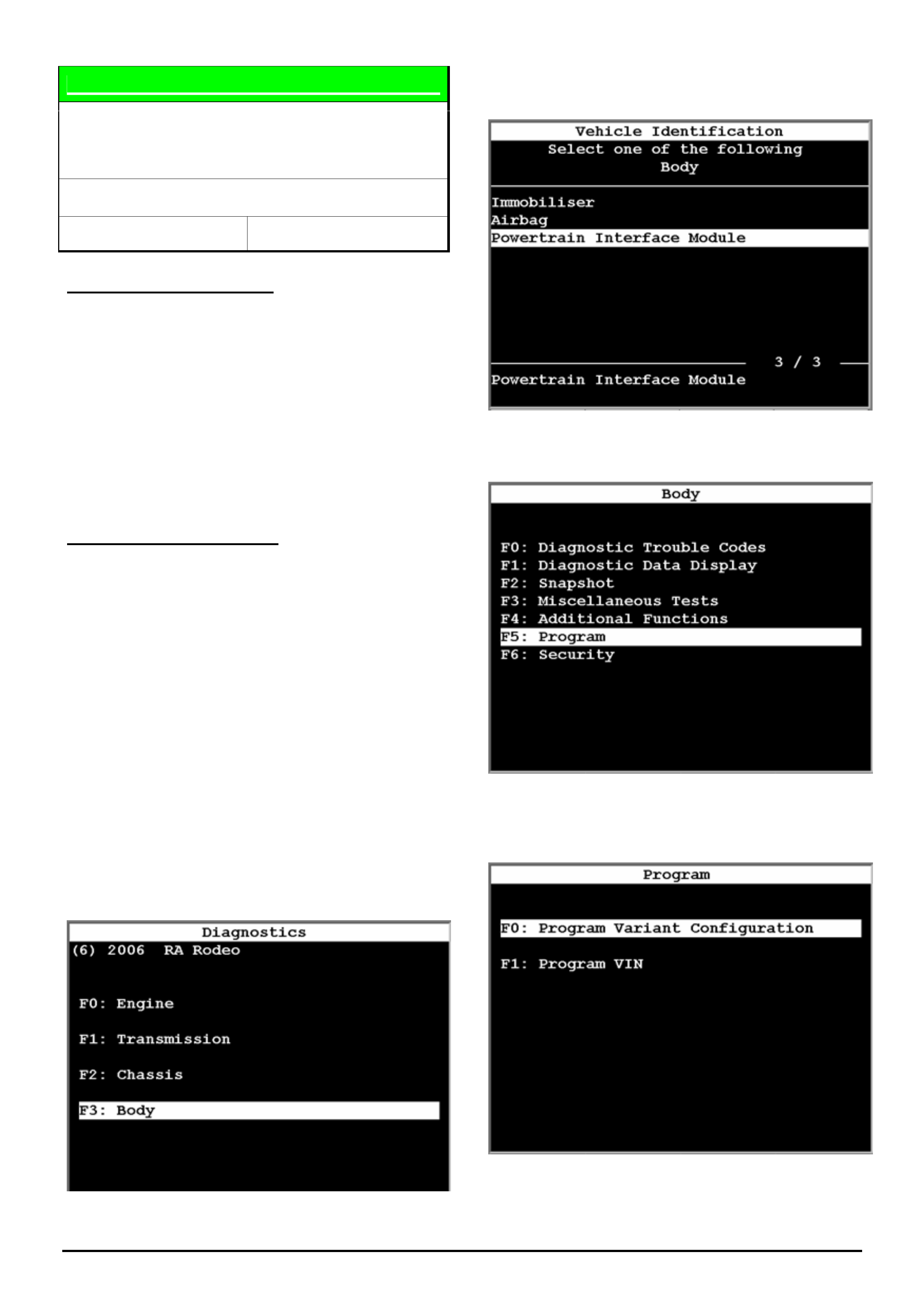
The procedure to re-configure the PIM
transmission type is shown below. This procedure
is also found in SIP Section 6E1 / 11.3 - PIM
Configuration
1 After selecting the vehicle type (RA Rodeo) and
model year, select the Body Option as shown
below.
2 Select the Powertrain Interface Module as
shown below.
3 Select the Program Option as shown below.
4 Select the Program Variant Configuration as
shown below.
HOLDEN SERVICE TECHLINES_________________________________________________________________________________JULY, 2006
8
Holden Techlines are written to inform technicians of conditions that may occur on some vehicles, and to provide information that could assist in the
proper service fix of a vehicle. If a condition is described, do not assume the service fix applies to a vehicle or that the vehicle will have that condition.
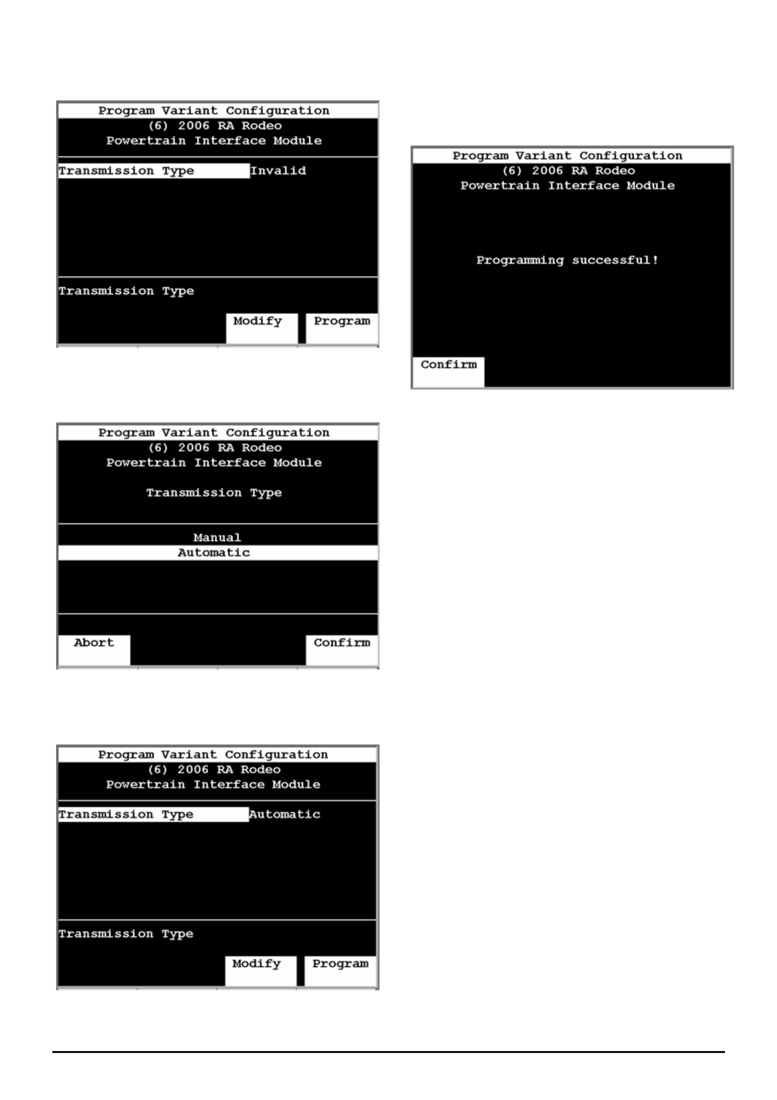
5 The following screen will then show. Now press the
“Modify” soft key
6 Select the appropriate transmission type then
press confirm
7 The following screen will now show. Press the
“Program” soft key
8 The following screen will now show. This is the
end of the programming process. Clear all DTC and
confirm operation of 4WD Low range and the PRNDL
Indicator lights.
HOLDEN SERVICE TECHLINES_________________________________________________________________________________JULY, 2006
10
Holden Techlines are written to inform technicians of conditions that may occur on some vehicles, and to provide information that could assist in the
proper service fix of a vehicle. If a condition is described, do not assume the service fix applies to a vehicle or that the vehicle will have that condition.
SERVICE PROCEDURE
Correct A/T Identification for SRTA Requests
VY, VZ, WL, V2, RA, VE, WM
Group 7B Ref. No. TL1148 - 0606
CONDITION
Incorrect SRTA exchange transmissions are being
received at Dealerships from SRTA.
CAUSE
Incorrect identification of transmission type requested
by Dealership personnel via incomplete/incorrect
information on SRTA TRANSMISSION ORDER FORM.
NOTE: Transmission serial numbers no longer carry
serial numbers that coincide with vehicle build date or
model year.
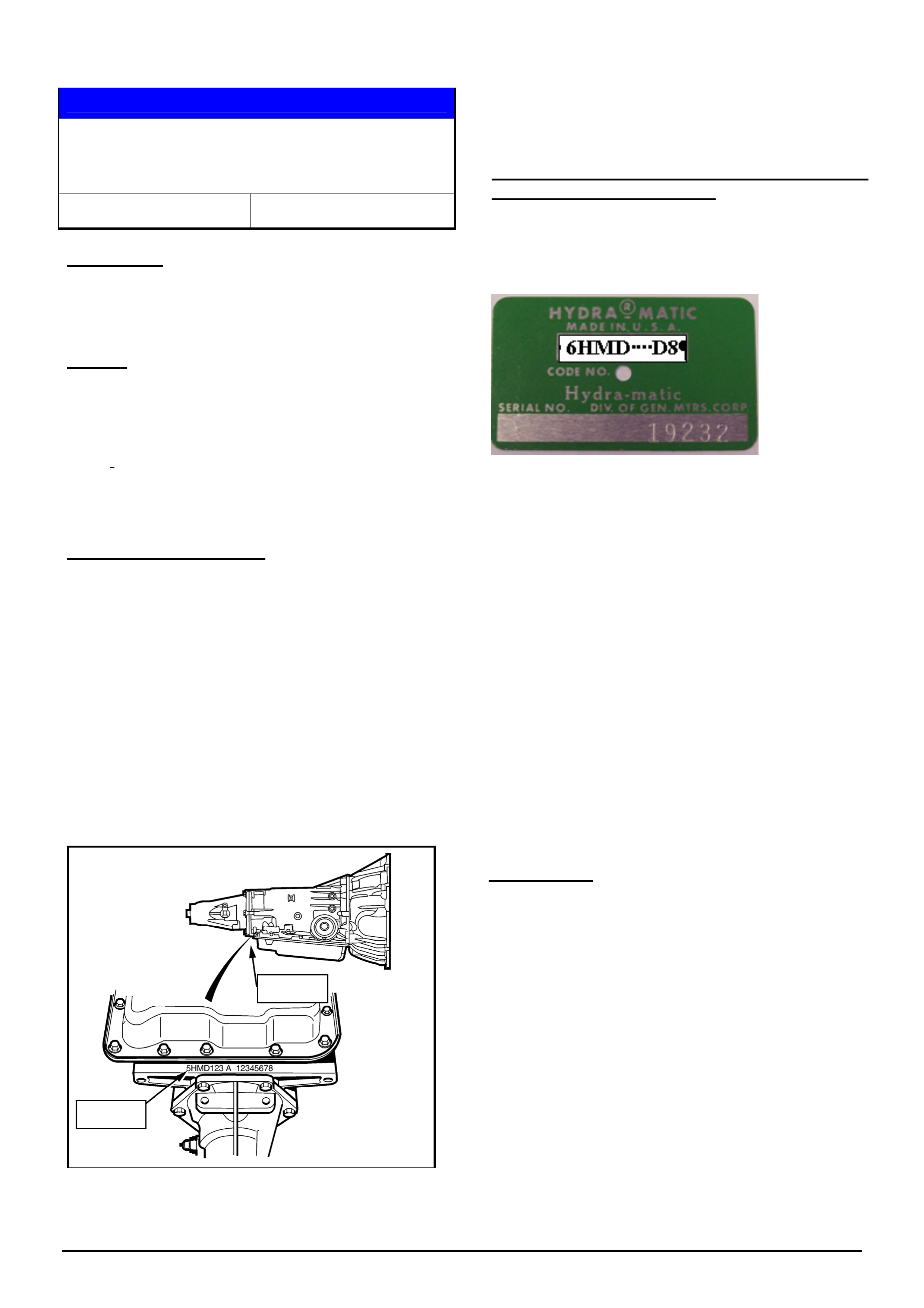
CORRECT PROCEDURE
(1). Vehicles with Original Equipment (OE)
Transmission:
The transmission serial number as read
off the transmission case must be
provided to SRTA to ensure that a correct
exchange transmission will be supplied.
The following diagram shows the location of the
transmission serial number – for recording on the
SRTA TRANSMISSION ORDER FORM:
(2). Vehicles fitted with a SRTA Transmission:
Transmission ID/Serial number location For
SRTA Transmissions ONLY
SRTA transmissions are identified by a GREEN plate
attached to the RH side of the transmission case with
the word “Hydramatic” at the top of the plate.
For Reference only: ACDelco® remanufactured
transmissions are identified by a BLUE plate attached to the
RH side of the transmission case with the word ACDelco at
the top of the plate.
Both of these plates “over-ride” the O.E. number
stamped on the trans. case, and include: Model
Identifier, Julian Date and Individual Transmission
Serial No. (as mentioned above).
This information MUST be used where a SRTA
transmission suffers a failure requiring replacement of
the unit. Warranty acceptance on such a unit is
defined by distance travelled, or date of fitting the unit
to date of failure (24 month/50000km parts warranty
applies).
NOTE: Both SRTA and ACDelco remanufactured
transmissions are painted silver and OE transmissions
are unpainted, plain cast alloy.
SRTA Action
SRTA will no longer supply exchange transmissions
based solely on either model or ISOVIN numbers
supplied on a SRTA TRANSMISSION ORDER FORM.
Forms supplied without serial numbers from the
transmission – as noted above - will not be honoured
and the Dealer will be requested to arrange for the
serial number – RECORDED FROM THE VEHICLE -
to be supplied.
To avoid customer inconvenience, ensure
that the transmission serial number is
recorded when the transmission is first
diagnosed as requiring replacement.
Serial No.
Serial No.
HOLDEN SERVICE TECHLINES_________________________________________________________________________________JULY, 2006
11
Holden Techlines are written to inform technicians of conditions that may occur on some vehicles, and to provide information that could assist in the
proper service fix of a vehicle. If a condition is described, do not assume the service fix applies to a vehicle or that the vehicle will have that condition.
SERVICE PROCEDURE
Installing New A/C Compressor - Oil Balance
Procedure
All
Group 2 Ref. No. TL1106 - 0606
A new compressor contains a complete A/C system oil
charge.
Therefore, whenever a compressor is replaced, the
following procedure must be performed in order to
maintain the correct amount of compressor lubricant in
the system.
DO NOT install a new compressor without first
performing the oil balance procedure.
OIL BALANCE PROCEDURE
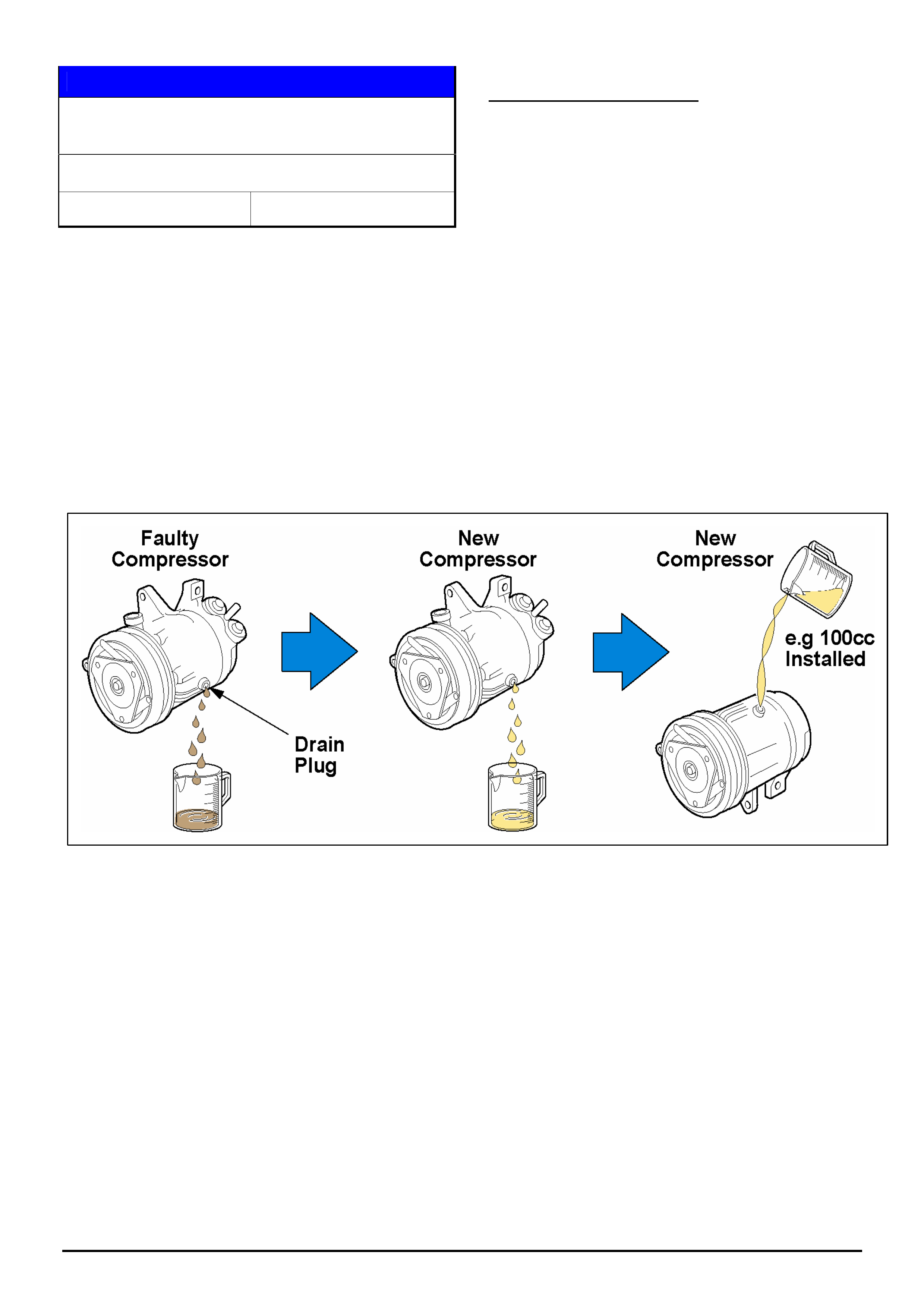
STEP 1. Drain and measure (and record) the quantity
of oil removed from the old compressor.
STEP 2. Drain the oil from the new compressor into a
clean measuring container.
STEP 3. Refill the new compressor with the new oil
removed in step 2, but using the same quantity as
drained from the old compressor in step 1.
NOTE: In cases where a refrigerant hose has blown or
a compressor housing is cracked, the complete A/C
system will have to be flushed to remove all traces of
oil and foreign material. The new compressor can then
be installed with no oil balance check required.
Step 1.
Drain, measure, and record
the quantity of oil removed
from the old compressor.
Step 2.
Drain the oil from the new
compressor into a clean
measuring container.
Step 3.
Refill the new compressor with
the new oil removed in step 2,
but using the same quantity as
drained from the old compressor
in step 1.
HOLDEN SERVICE TECHLINES_____________________________________________________________________________AUGUST, 2006
13
Holden Techlines are written to inform technicians of conditions that may occur on some vehicles, and to provide information that could assist in the
proper service fix of a vehicle. If a condition is described, do not assume the service fix applies to a vehicle or that the vehicle will have that condition.
DIAGNOSIS HINT
High Pressure Oil System - Pressure
Diagnosis
UBS Jackaroo, 4JX1-TC Diesel Engine
Group 6A Ref. No. TL1141 - 0607
This techline contains details of a test tool (refer Figure
2) to aid in the diagnosis of pressure faults in the High
Pressure Oil System in 4JX1-TC engines.
Using this test tool in accordance with the test
procedure, will help technicans to correctly identify
any leaks or defective components in the “high
pressure oil system”.
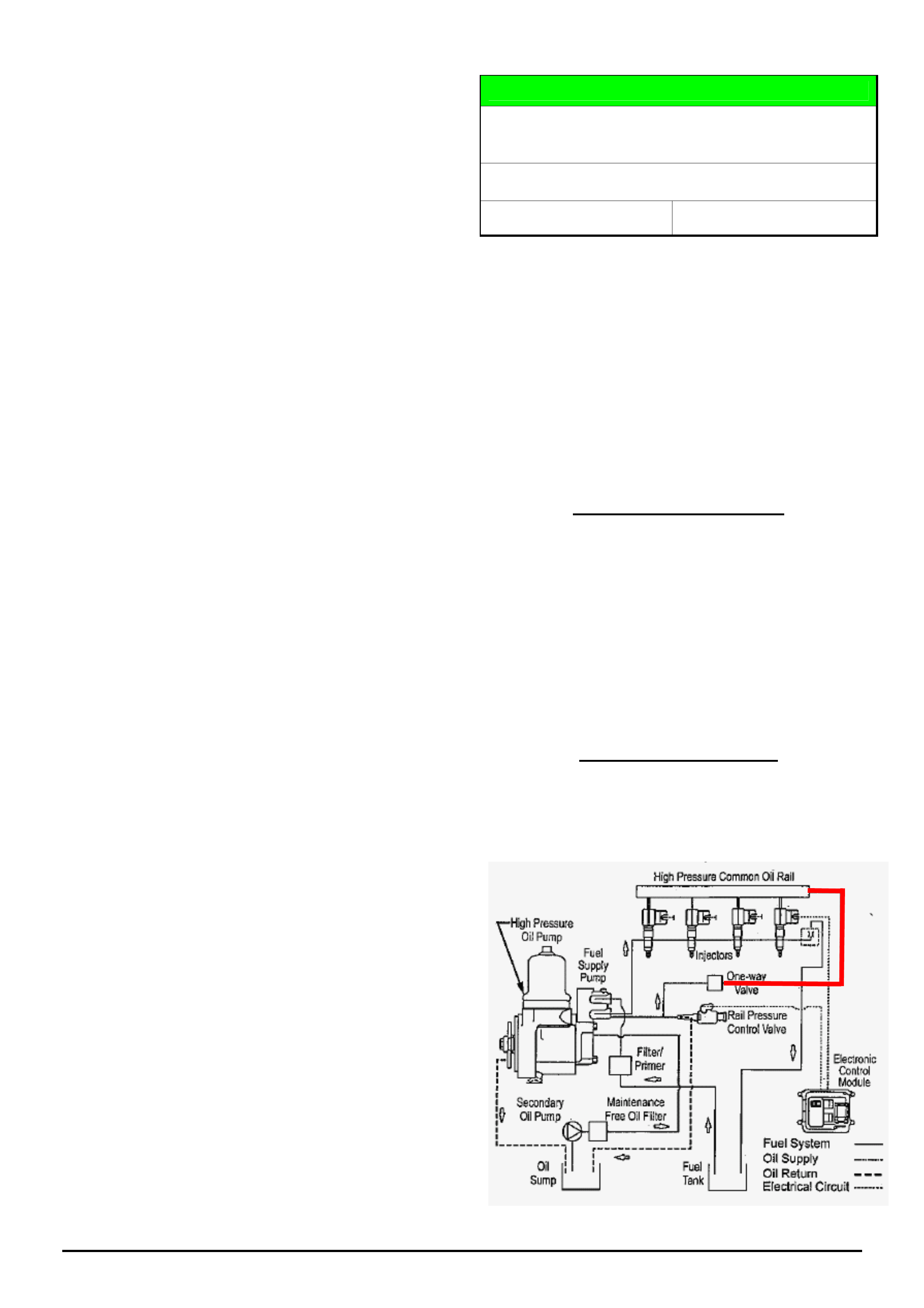
High Pressure Oil System componentry consists of oil
pump, common oil rail (manifold), rail pressure control
valve, rail pressure sensor, one way valve and
associated piping.
Manufacture of test tool
Figure 2 contains sketch plans for a test tool which is
to be installed into the High Pressure Oil System for
diagnosis purposes only.
Due to the high pressures this tool is subjected to,
the manufacture of this tool SHOULD be
outsourced to a company which has expertise in
hydraulic hoses and fittings.
All components used must be able to handle oil
pressure up to 5000 psi (35 MPa).
Installation of test tool
The tool is to be installed between the High Pressure
Common Oil Rail and the one way valve located on the
left hand side of engine. (refer red line in diagram
below. This will require removal of the existing steel oil
pipe in this location.
Figure 1. Install Test tool at location of red line

HOLDEN SERVICE TECHLINES_____________________________________________________________________________AUGUST, 2006
14
Holden Techlines are written to inform technicians of conditions that may occur on some vehicles, and to provide information that could assist in the
proper service fix of a vehicle. If a condition is described, do not assume the service fix applies to a vehicle or that the vehicle will have that condition.
Test Procedure.
STEP 1. Test Tool Installation.
The test tool must be installed in the orientation as
shown in Figure 2. When installed, the tap must be
located between the oil pressure gauge and the tappet
cover as shown.
After installation, proceed to Step 2.
STEP 2 - TAP OPEN. (engine stationary and engine
cranking)
These tests enable the Oil Rail Pressure Sensor to be
checked for accuracy by comparing the reading
obtained with Tech 2 to the reading on the oil pressure
gauge.
NOTE: The procedure for obtaining a reading with
Tech 2 is contained in SIP under 4JX1 engine
diagnostics.
With the Engine NOT cranking - the Rail Oil
Pressure should be 0 +/- 0.2 Mpa – on Tech2
If the above specification is NOT met, check the
injector harness connector (near oil dipstick tube) for
oil ingress to the connector.
If “flooded” with oil, the Rail Pressure Sensor and
Injector Harness will require replacing.
With the Engine cranking - compare the reading
obtained with Tech 2 to the reading on the oil pressure
gauge. If the readings are similar then the Oil Rail
Pressure Sensor is okay. If they differ greatly then the
sensor should be replaced.
For those cases where the Oil Rail Pressure Sensor
and the pressure gauge on the “test tool” show very
little or no oil pressure, proceed to the “Tap Closed”
procedure as follows.
STEP 3. - TAP CLOSED.
Close the tap on the test tool then crank the engine
over. Monitor the Rail Pressure Control Valve % on
Tech2. This should go to 98% after a few seconds of
cranking.
This test checks the integrity of the oil system prior to
tap - i.e. from the tap back to the high pressure pump.
If the system is able to develop high pressure with the
tap closed, the cause of any pressure loss being
investigated will be AFTER the tap - (i.e somewhere
under the rocker cover).
CAUTION: The engine MUST NOT be cranked any
longer than necessary to confirm if high pressure is
obtainable. It is possible the oil pressure could
exceed 4000psi or 28 bar. The starter motor will
begin to “labour” when high pressure is reached.
Hints
• The actual rail oil pressure must be in excess of 3.5
Mpa for the injectors to enable. This can be seen on
Tech 2 data.
• Snapshots are recorded at 2 frames per second.
When conducting a snapshot try and capture data in
a “block” of 10 seconds.
Achieving these blocks of constant information
makes “reading” snapshot data on TIS 2000 much
easier.
E.g. Key on, engine off 10 Seconds
Cranking 10 Seconds
Idle 10 seconds
Full throttle 10 seconds.
If any further assistance is required please contact
TAS LCV group.

HOLDEN SERVICE TECHLINES______________________________________________________________________________________________________________________AUGUST, 2006
15
UBS Jackaroo 4JX1 - High Pressure Oil System - Test Tool
Figure 2.
Fitting A
- attached to one way (non-return)
valve on LH side of Engine.
Oil Gauge
0 to 5000
p.s.i. /
35 MPA
In-line tap. Must
be able to handle
5000psi/ 35000kpa
CHECKING PROCEDURE: (Refer
to page 1 for complete details)
- Tap open checks accuracy of the
Rail Sensor.(check against reading
with Tech 2)
- Tap closed checks system integrity
prior to tap.
If high pressure is achievable then
leak is after tap (under the Tappet
Cover).
Fitting B
– Attached to Oil Rail
NOTE:
This Test Tool assembly fits in place of the
steel pipe part number 8972091980.
It is recommended to purchase 8972091980
from spare parts and then have the gauge and
tap fitted into the line.

HOLDEN SERVICE TECHLINES_____________________________________________________________________________AUGUST, 2006
17
Holden Techlines are written to inform technicians of conditions that may occur on some vehicles, and to provide information that could assist in the
proper service fix of a vehicle. If a condition is described, do not assume the service fix applies to a vehicle or that the vehicle will have that condition.
DIAGNOSIS INFORMATION
Subject: HARD START or NO START
Model: RA RODEO Petrol & Diesel
Group: 6C Ref. No. TL0955A - 0607
This Techline supercedes the previous one TL0955-0506 in Issue 6, July 2005. It is Revised by changing to a Flow Chart
format. A customer questionaire has also been added.
IMPORTANT
• Despite all the previous techlines published on this subject, many
immobilisers are being replaced unnecessarily for the above
condition.
• Please note that from publication of this techline, any immobiliser
that is replaced unnecessarily will not be accepted under warranty.
• TO AVOID THE UNNECESSARY REPLACEMENT OF IMMOBILISERS
the “Recommended Procedure” shown in the box below should be
followed.
►►►►► RECOMMENDED PROCEDURE ◄◄◄◄◄◄
1. A set of questions relevant to the correct diagnosis of the immobiliser have been
developed and assembled into a Customer Questionnaire. It is recommended that
your Service Advisor complete the questionnaire with the customer when booking
vehicle in.
2. Customer Questionnaire to be attached to the Repair Order for technician’s
reference as a “tool” to assist with correct diagnosis of the immobiliser.
3. Technician to proceed with problem diagnosis commencing with flow Chart 1.
NOTE: Below is a list of previous techlines published in relation to this subject. These may be used for
reference, however, all the information in them has been consolidated into this techline.
TL0955-0506 Group 6C - July 2005 Hard Start or No Start (summary of previous information)
TL0826-0411 Group 6C - Dec 2004 Intermittent Crank but No Start (ECU revised software)
TL0813-0410 Group 12 - Nov 2004 Engine difficult to start, cranks, starts, stalls (battery voltage low)
TL0693-0404 Group 12 - May 2004 Immobiliser VIN programming
TL 0541A-0404 Group 12 - May 2004 Intermittent No Crank or No Start. (Immobiliser related)
HOLDEN SERVICE TECHLINES_____________________________________________________________________________AUGUST, 2006
18
Holden Techlines are written to inform technicians of conditions that may occur on some vehicles, and to provide information that could assist in the
proper service fix of a vehicle. If a condition is described, do not assume the service fix applies to a vehicle or that the vehicle will have that condition.
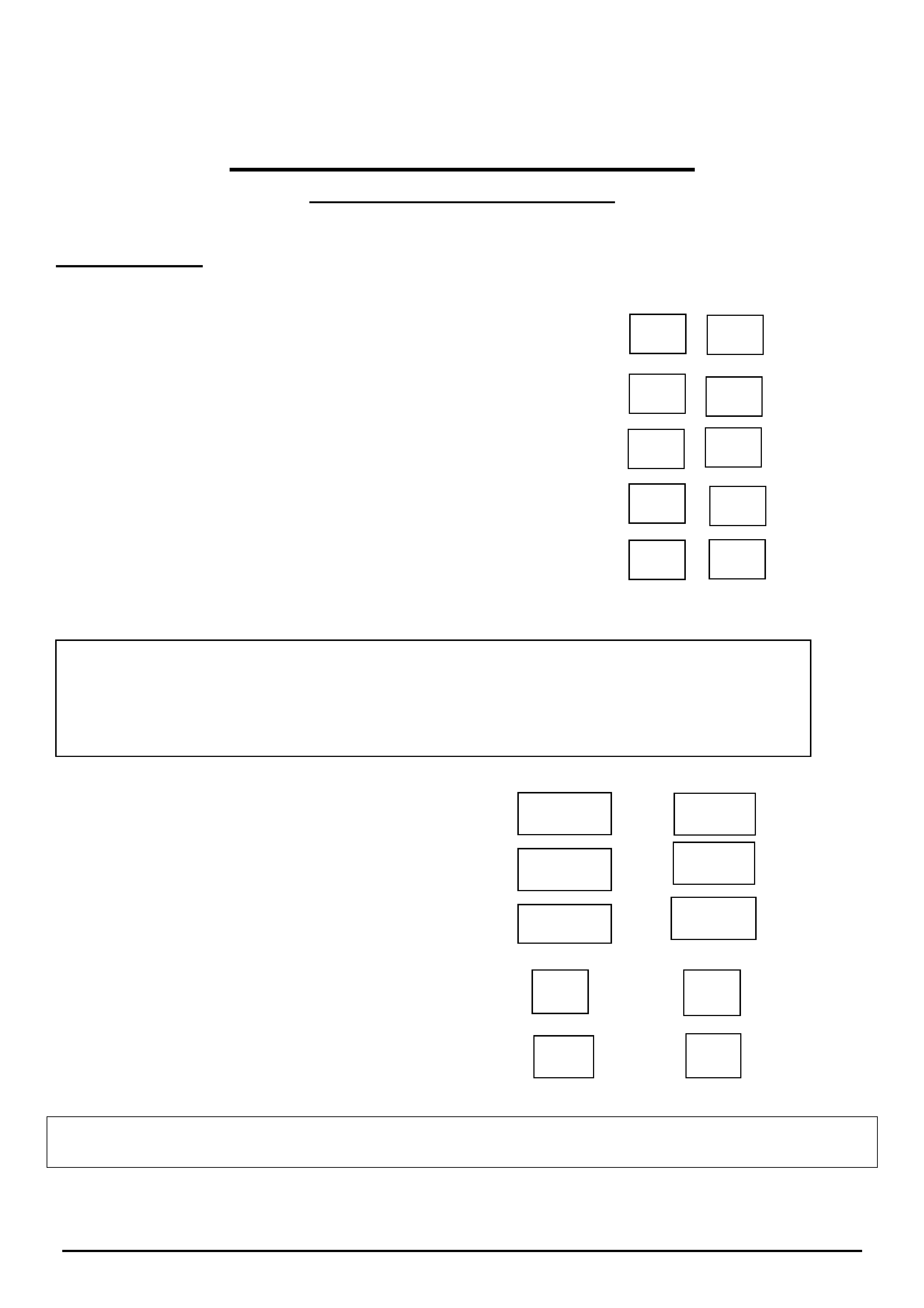
RA Rodeo Hard to Start
CUSTOMER QUESTIONAIRE
(To be filled in by Service Advisor)
Service Advisor to ask customer the following questions at time of vehicle book-in.
Circle correct answer
1/ Does the vehicle ALWAYS Crank over when trying to start?
2/ Does the Check Engine Light flash while attempting to crank engine?
3/ Does the Engine start then stall?...........................................................................................
4/ Does the Engine Crank but Check Engine Light stays off?
5/ Is the fault present with BOTH Ignition Keys?
6/ Get the customer to describe how they normally reproduce the fault?
7/ How often does the fault occur? Frequency No. of times
8/ Customer asked to bring in BOTH ignition keys when
presenting vehicle for repairs.
9/ Customer informed on how to re-start Engine AFTER
turning ignition off and waiting 20 Seconds.
When completed, attach this sheet to the Repair Order for the Technician’s information.
Yes No
Yes No
Yes No
Yes No
Yes No
Daily
Weekly
Monthly
Yes No
Yes No
HOLDEN SERVICE TECHLINES_____________________________________________________________________________AUGUST, 2006
19
Holden Techlines are written to inform technicians of conditions that may occur on some vehicles, and to provide information that could assist in the
proper service fix of a vehicle. If a condition is described, do not assume the service fix applies to a vehicle or that the vehicle will have that condition.
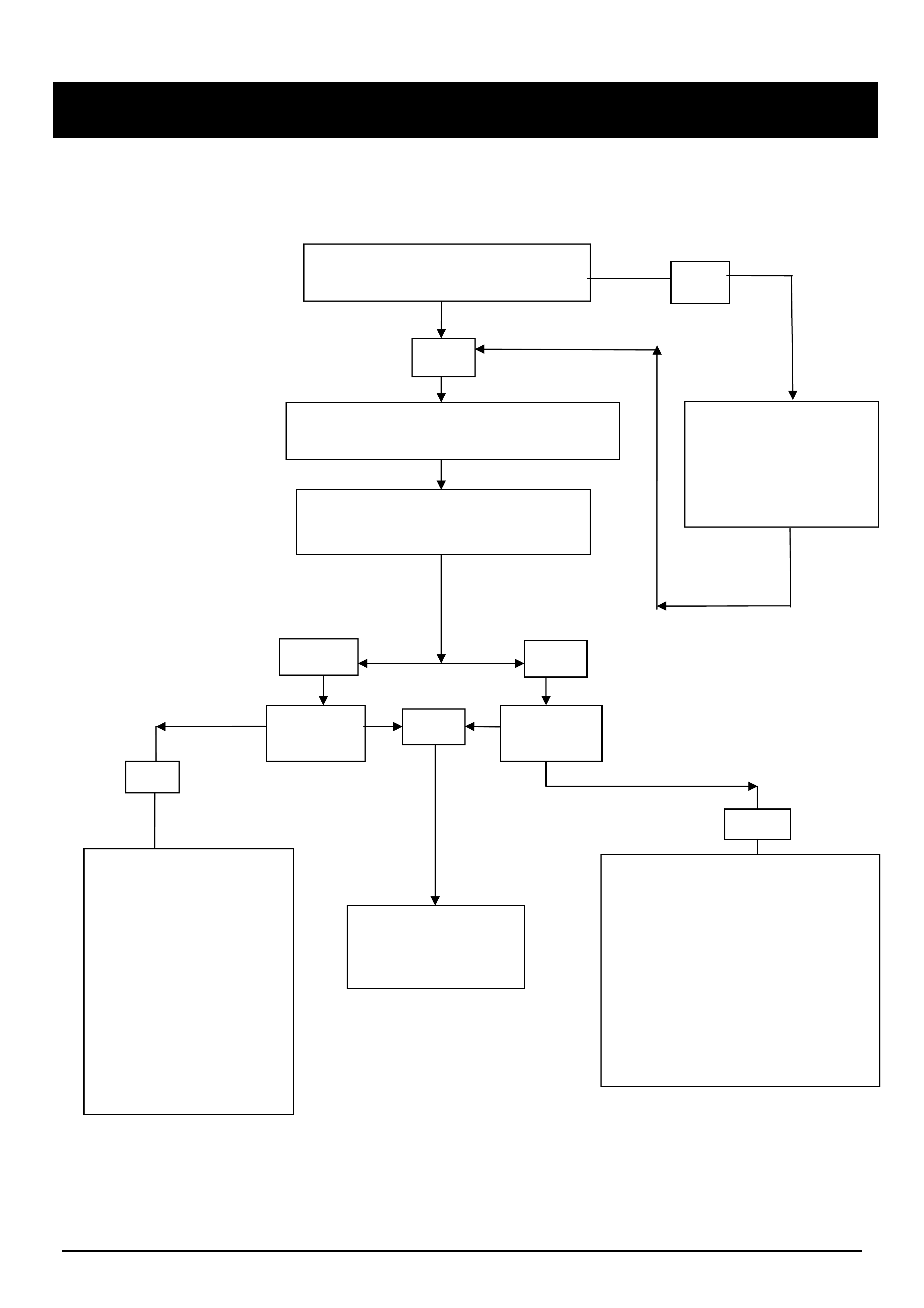
Chart 1 RA Rodeo Hard Start
YES NO
Does the engine ALWAYS Crank
when trying to start the Engine.
Is the C.E.L
Flashing ?
Is the C.E.L
Flashing ?
No
Fault is NOT in the
Immobiliser system.
Refer to “Cranks won’t
run” chart in LCRV SIP in
the Engine and
Driveability Section of
applicable engine, under
Symptom Diagnosis.
If further Assistance is
required contact TAS
Proceed to
Preliminary
Checks
Yes
No
Fault is NOT in the
Immobiliser system.
Refer to Starting and Charging in
LCRV SIP under Electrical –
System Repair - 8A of Symptom
Diagnosis.
Do not replace Immobiliser.
If further Assistance required contact
TAS.
.
Do you have a completed copy of
the Customer Questionaire? No
Yes
Use information gathered from Customer
to answer following flow chart questions.
Obtain a completed
questionaire from the
Service Advisor.
Do you now have a
completed form ?

HOLDEN SERVICE TECHLINES_____________________________________________________________________________AUGUST, 2006
20
Holden Techlines are written to inform technicians of conditions that may occur on some vehicles, and to provide information that could assist in the
proper service fix of a vehicle. If a condition is described, do not assume the service fix applies to a vehicle or that the vehicle will have that condition.
PRELIMINARY CHECKS
► THE FOLLOWING MUST BE COMPLETED ON ALL VEHICLES PRIOR TO PROCEEDING TO CHART 2 ◄
1. Battery Check.
The Battery MUST be checked with a Hydrometer and a load tester. The cranking voltage should be above 10.5
Volts.
2. DTC Checks.
• Are there any DTC’s logged in the engine ECU or the Immobiliser ICU? If so, what are they? Include the
fault code number and Tech 2 descriptions.
• If Present DTC’s are shown, perform the relevant flow chart diagnosis for the DTC’s SEE NOTE A
• If History DTC’s are shown, the DTC charts can still be used to identify and check the relevant circuits and
wiring associated with the DTC.
• NOTE A. DTC B8007 can be set falsely by cycling the Ignition key from On – Off – On within 30 seconds.
Do not diagnose by this code if this is the case.
• NOTE B. If there are no DTC’s in the engine or Immobiliser ICU, the problem is probably NOT Immobiliser
related. In this case, perform usual engine no start / hard start diagnosis, E.G. fuel pressure, fuses, power
& earth supplies, etc. Use Tech 2 typical data values to help in diagnosis.
3. Body Earth Checks.
IMPORTANT: It is critical that the following checks and cleaning are carried out properly.
VOLT DROP CHECKS. - These checks are necessary to identify any poor earths which need rectification.
Volt drop checks should be done with an electrical load applied by turning on all
lights, heater fan, demister etc. with engine idling if possible.
1. Check for voltage drop across each earth circuit to battery negative post at all 5 earth points (shown
below) and record. Volt drop must be less than 0.2 Volt. Use a digital multimeter with at least 10 Mega
ohm input impedance (tool J39200 or equivalent).
2. If volt drop is above 0.2 Volt then rectify/repair cause of excessive volt drop.
3. Please report any excessive volt drops (including location) to Holden on a PIR.
• Earth P-5. Location – Battery negative terminal.
Ensure the terminal is clean and tight.
• Earth P-6. Location - Battery tray.
Paint to be cleaned from between Earth terminal and Battery Tray. Terminal to be cleaned.
NOTE -This earth point is the only link the earthing system has between the fully rubber mounted
cabin and the battery.
• Earth C-2 Location - R.H. inner guard.
Paint to be cleaned from between Earth terminal and Battery Tray. Terminal to be cleaned.
• Earth C-36 Location - L.H. inner guard.
Paint to be cleaned from between Earth terminal and Battery Tray. Terminal to be cleaned.
• Earth C-109. Location - Under LH front seat.
Paint to be cleaned from between Earth terminal and Battery Tray. Terminal to be cleaned.
HOLDEN SERVICE TECHLINES_____________________________________________________________________________AUGUST, 2006
21
Holden Techlines are written to inform technicians of conditions that may occur on some vehicles, and to provide information that could assist in the
proper service fix of a vehicle. If a condition is described, do not assume the service fix applies to a vehicle or that the vehicle will have that condition.
The earth points C2, C36,
and C109 all earth to the
cabin.
4. Engine Earth Check
All Engine Earths are to be cleaned.
Refer to SIP /Eng. and Driveability /Ground Points - to view an “Earth” block diagram to assist in locating where
each light, module, switch, etc. is Earthed to for a better understanding of the Earthing system in RA Rodeo
vehicles.
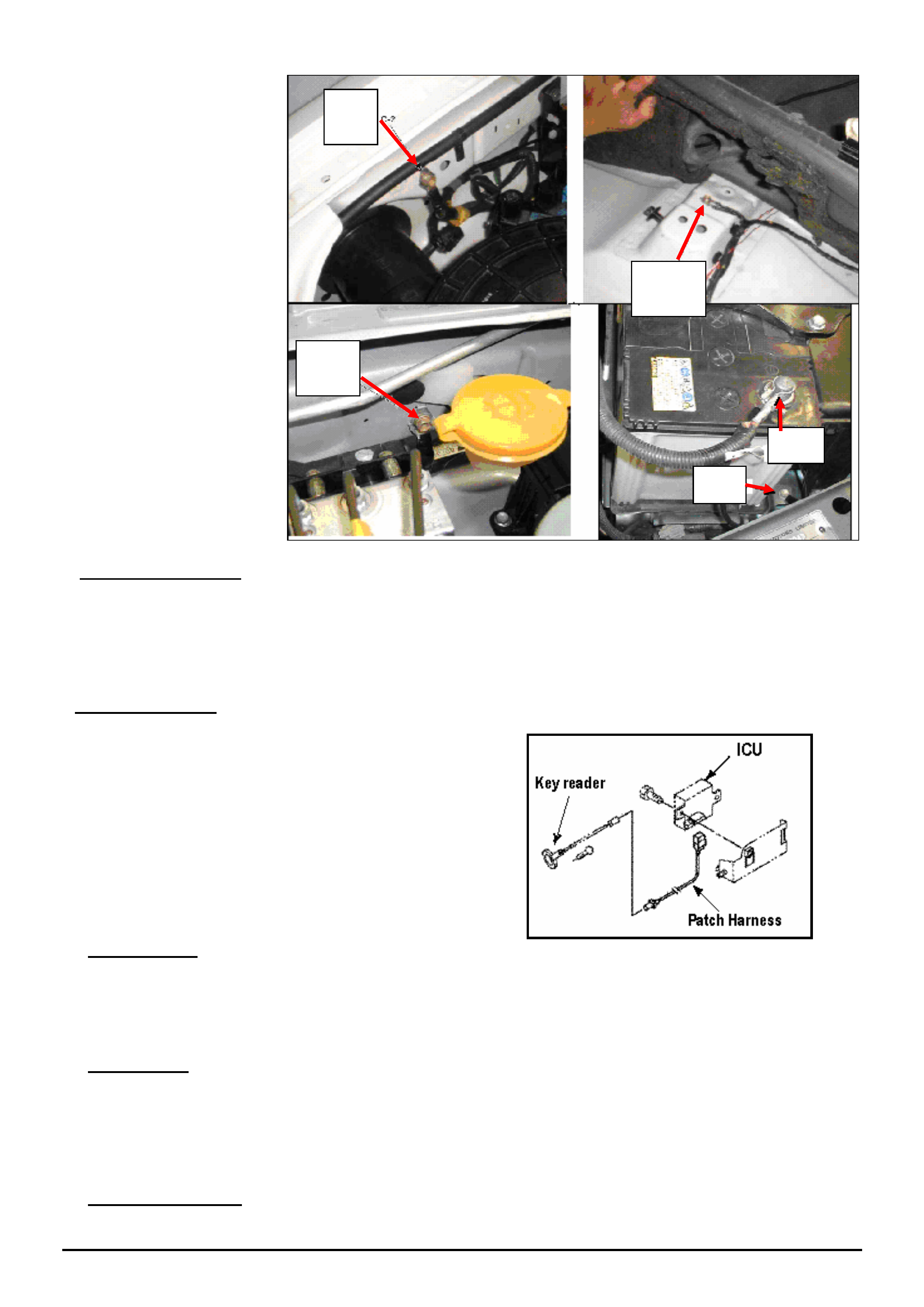
5. Terminal Checks.
Check terminal retention from the Key Antennae to
the Immobiliser, via Patch Harness.
HINT. This can be done by removing a male
terminal from the Antenna / Key reader Patch
harness and use this terminal to test retention of
female terminals. Resize terminals if required to
increase retention.
6. ECM Software
The ECM must have latest calibration installed. Please request Info. via SPS on Tech 2 and check if new ECM
software is available. Update ECM via SPS on TIS 2000 if newer Software available.
If the vehicle is a 3.5 V6 built before engine number 240817, program engine ECU with the latest TIS software.
NOTE: revised engine ECU software was fitted in production from engine number 240817
7. Accessories.
Non genuine electrical accessories that are wired into the vehicle are a major contributor to hard start problems,
and must be removed before proceeding with diagnosis.
NOTE: There is a genuine accessory “Patch Harness” available for Cellular Phones. (Refer to Techline TL0922-
0504 May 2005).
8. Proceed To Chart 2.
C-2
C-109
C-36
P-6
P-5

HOLDEN SERVICE TECHLINES_____________________________________________________________________________AUGUST, 2006
22
Holden Techlines are written to inform technicians of conditions that may occur on some vehicles, and to provide information that could assist in the
proper service fix of a vehicle. If a condition is described, do not assume the service fix applies to a vehicle or that the vehicle will have that condition.
Chart 2 Engine Cranks with CEL Flashing
Check the part number on
the Immobiliser Control
Unit.
Petrol 8973773230
Diesel 8973773240
Is the Part number
correct?
No
Replace Immobiliser with
part Number
Petrol 8973773230
Diesel 8973773240
Yes
Is the VIN earlier than
Breakpoint VIN below?
4JH1 -
MPATFS77J4H536880
6VE1 -
Fill in TAS case management form and contact TAS
Light Commercial for further assistance.
Have Service Advisors sheet and this chart attached to
case Management form prior to calling TAS.
No
Do NOT
replace
Immobiliser
The Preliminary
checks are to be fully
completed. Please
complete prior to
proceeding
Yes
Yes
Does the vehicle have any Non-
genuine Accessories Fitted?
Have all of the PRELIMINARY checks been completed?
No Yes
Yes
No
Accessories MUST be wired to Battery Positive
and Negative. Refer to Preliminary Checks
Are accessories correctly wired to Battery?
HOLDEN SERVICE TECHLINES__________________________________________________________________________ SEPTEMBER, 2006
7
INFORMATION
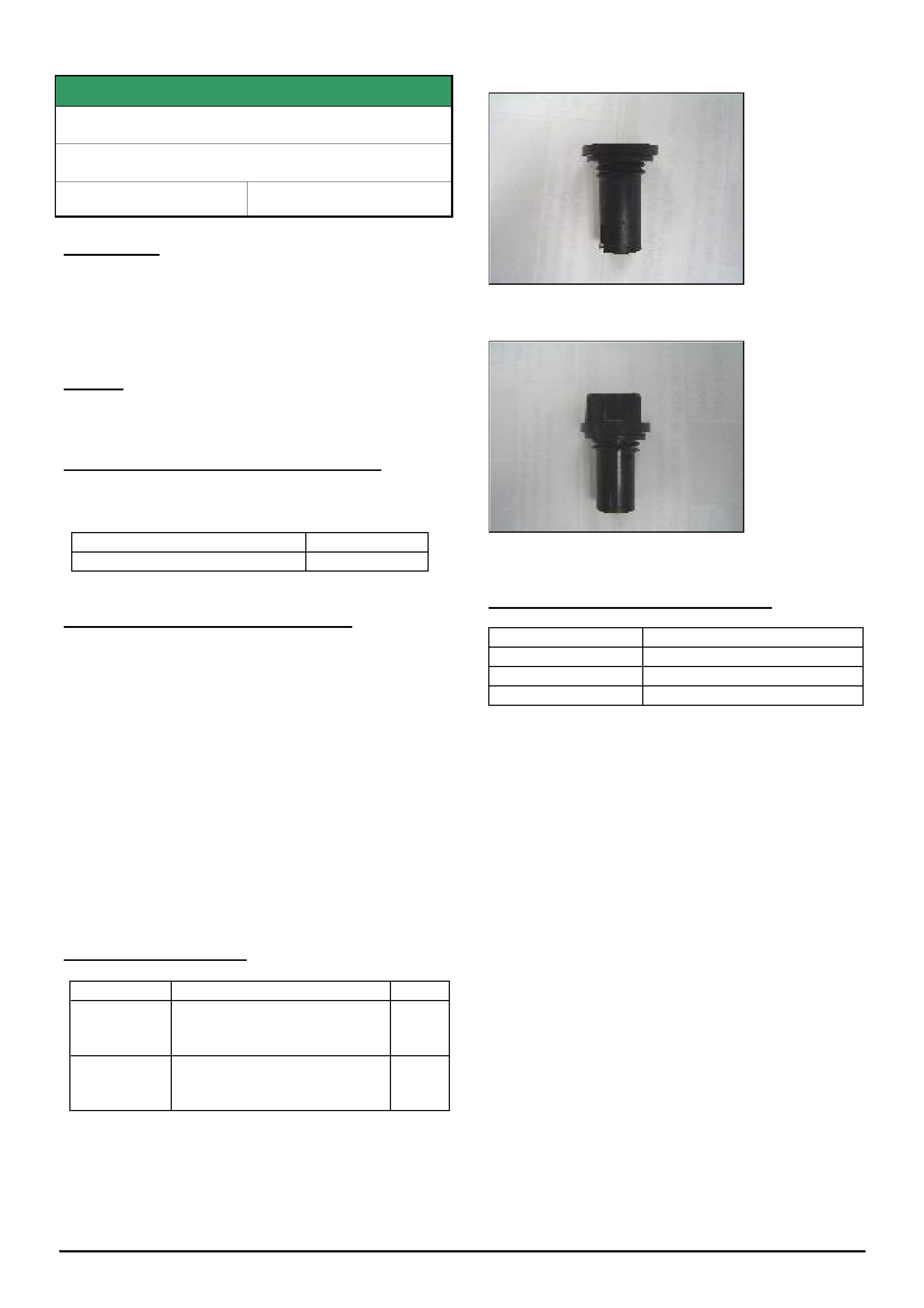
Cruise Control Inoperative after Fitment
RA Rodeo 6VE1 Petrol & 4JH1 Diesel
Group 12 Ref. No. TL1178 – 0608
This techline is issued to inform technicians of a
problem that may be encountered when fitting the
accessory cruise control kit to the above model.
The technician may find that when test driving the
vehicle after fitting cruise control, the vehicle will not
maintain the set speed even though the cruise set light
is illuminated on the cluster.
Almost all cases of the above complaint have found to
be caused by the cruise control actuator wiring being
incorrectly fitted into the Servo Connector Housing.
Therefore, when the terminals are fitted to this
connector, take the utmost care to ensure that the
male terminals are correctly engaging with the
corresponding female terminals in the connector. If not
enough care is taken, it is possible for the male
terminals to “push over” to the side causing poor or no
contact with the corresponding female terminal.
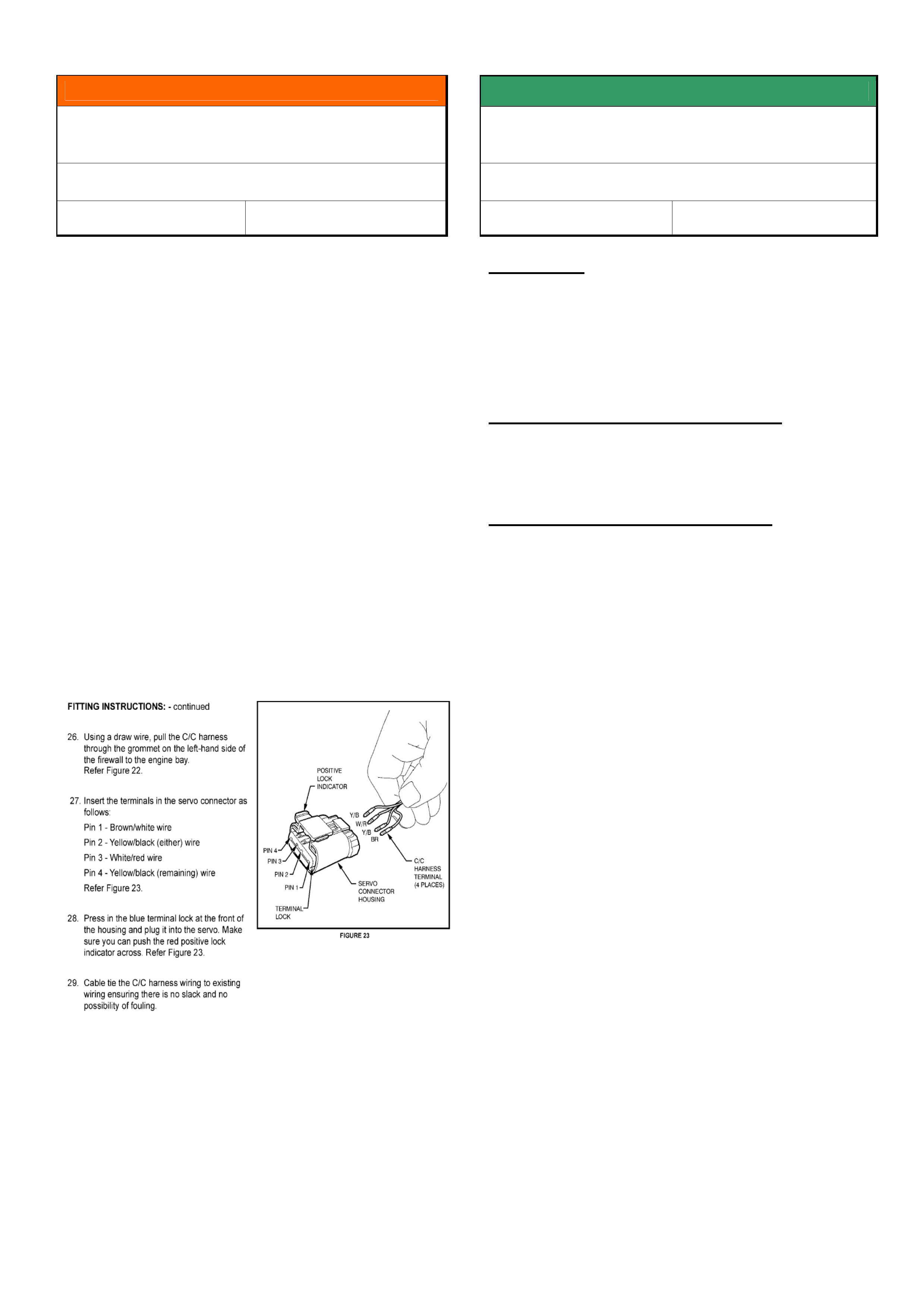
Shown below is page 13 of the cruise control
accessory fitting instructions for reference
SERVICE FIX
Fuel Gauge Drops To Empty & DTC P0460
Sets In The Engine ECU
RA, all with HFV6 MY06
Group 12 Ref. No. TL1164 - 0608
CONDITION
Customers may advise their fuel gauge drops to empty
and the low fuel light comes on or “Fuel Gauge Error”
message displayed in instrument cluster.
DTC P0460 "Fuel Level Sender range / performance"
sets in the engine ECU
CORRECTION – Vehicles In Service
On any vehicle with the above condition reprogram the
engine ECU as per the standard SPS process using
Tech 2 and TIS 2000 version 74 or later.
WARRANTY CLAIM INFORMATION
Use standard Labour Times found in the Warranty
Information section of the current PV SIP disc.