FD1257
05NOV04
COPYRIGHT
Reproduction in whole or part
prohibited without written approval
HOLDEN LTD
Division of HOLDEN Ltd ACN 006 893 232
FITTING INSTRUCTIONS FOR
AH ASTRA REAR PARKING SENSORS
TOOLS REQUIRED:
Trim Release Tool, 2.0 mm Drill Bit, Spade Drill Bit (P/N 92147946), Clean Cloth, Hi-tech Cleaning Pad (Supplied),
Guide Wire (approx. 600 mm) Torx Bit No 20.
Page 1 of 13
Part No. 92148370
FD1257
05NOV04
COPYRIGHT
Reproduction in whole or part
prohibited without written approval
HOLDEN LTD
Division of HOLDEN Ltd ACN 006 893 232
FITTING INSTRUCTIONS FOR
AH ASTRA REAR PARKING SENSORS
FITTING INSTRUCTIONS:
1. Cut-out the templates on pages 12 - 13. Check that the
scale on the template is correct. Fit the templates on the
vehicle as indicated.
L-Left - Template 1 - Page 12.
CL - Centre Left - Template 2 - Page 12.
CR - Centre Right - Template 3 - Page 13.
R-Right - Template 4 - Page 13.
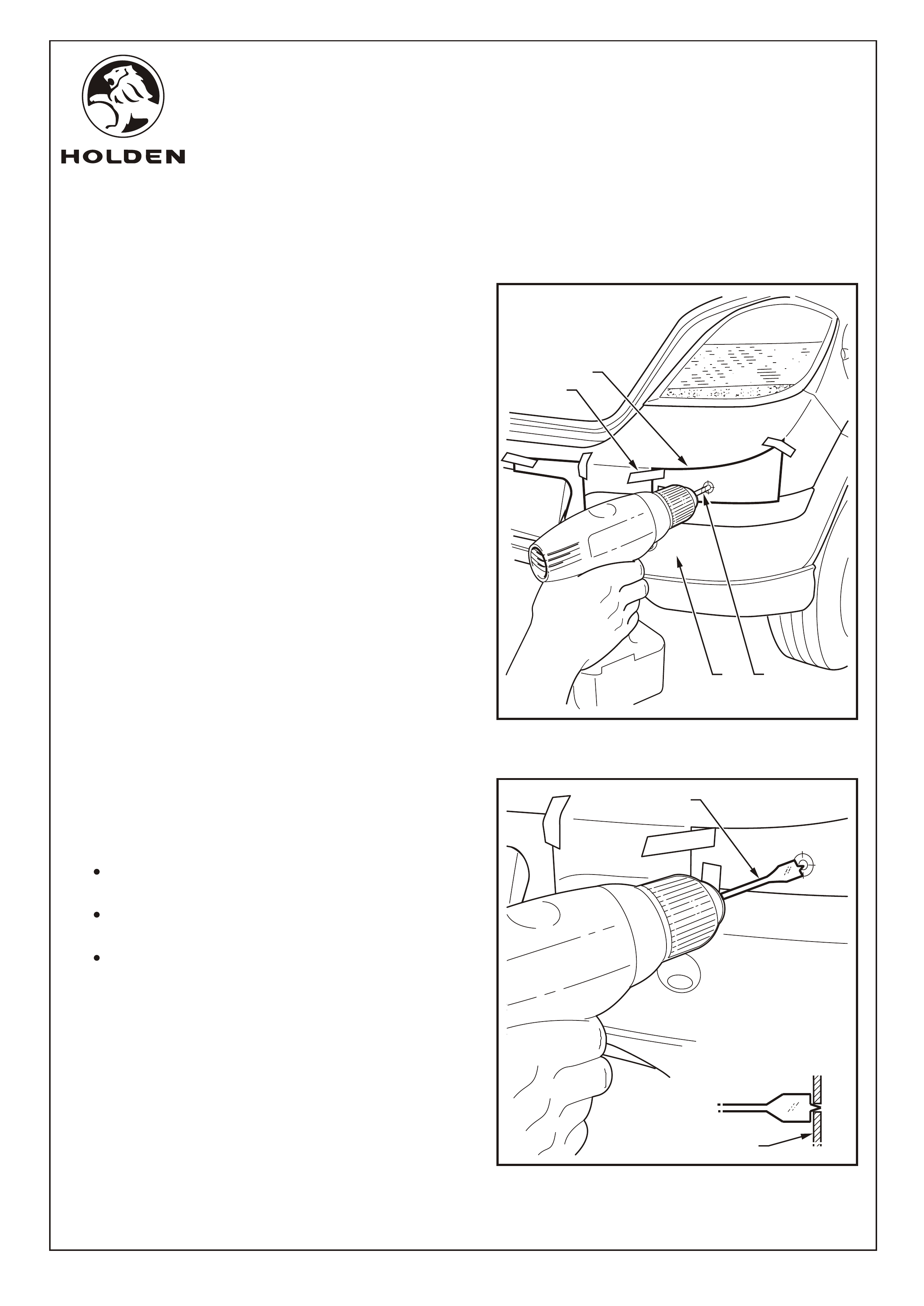
Place masking tape (1) over the area of the bumper (2)
fascia to be drilled. Refer to Figure 1.
2. Drill pilot holes (3) through the templates (4) and fascia
(4 places) using a 2.0 mm drill bit. Refer to Figure 1.
3. Remove the templates and use the spade bit (1) to make
22.2mm dia. holes (4 places) through the fascia (2).
Refer to Figure 2.
IMPORTANT:
Use only the spade drill bit as a normal drill bit or
hole saw may damage the bumper fascia.
Ensure the spade drill bit remains square with
the bumper fascia.
Use 1,500 - 2,000 RPM drill speed only to avoid
damaging the bumper fascia.
Ÿ
Ÿ
Ÿ
2
FIGURE 1
FIGURE 2
1
4
3
2
1
Page 2 of 13
FD1257
05NOV04
COPYRIGHT
Reproduction in whole or part
prohibited without written approval
HOLDEN LTD
Division of HOLDEN Ltd ACN 006 893 232
FITTING INSTRUCTIONS FOR
AH ASTRA REAR PARKING SENSORS
FIGURE 4
FITTING INSTRUCTIONS: - continued...
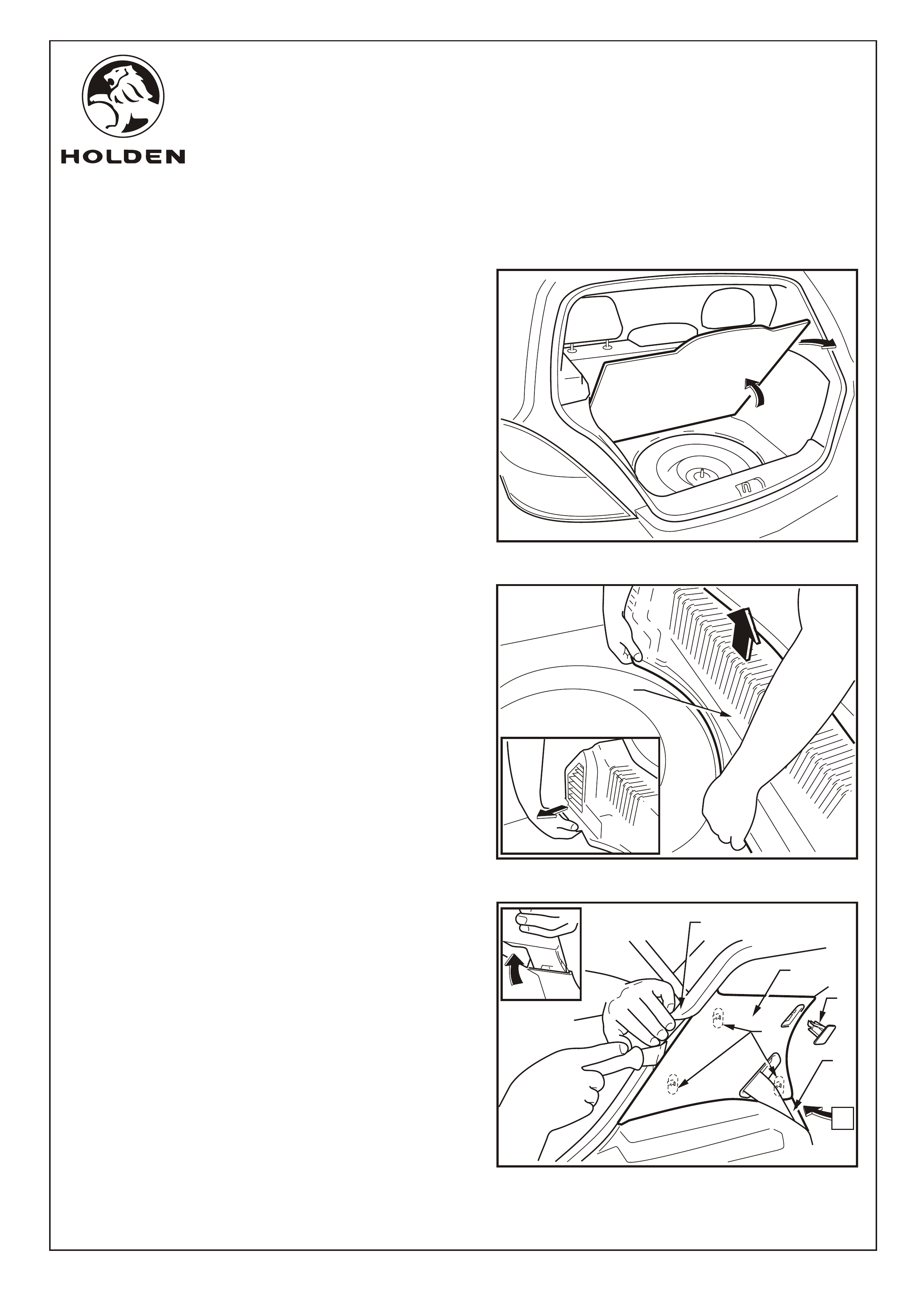
4. Open rear hatch and remove the parcel shelf and spare
wheel cover. Refer to Figure 3.
5. Remove the rear compartment trim (1) by pulling to the
centre of the vehicle to release the retaining clips. Once
released pull the trim up and remove from the vehicle.
Refer to Figure 4.
NOTE: Steps 6 to 11 will be repeated on both sides of the
vehicle.
CAUTION: Wiring for the side air bag (if fitted) runs
behind the "C" pillar top trim care, should be taken when
removing the trim not to damage the wiring.
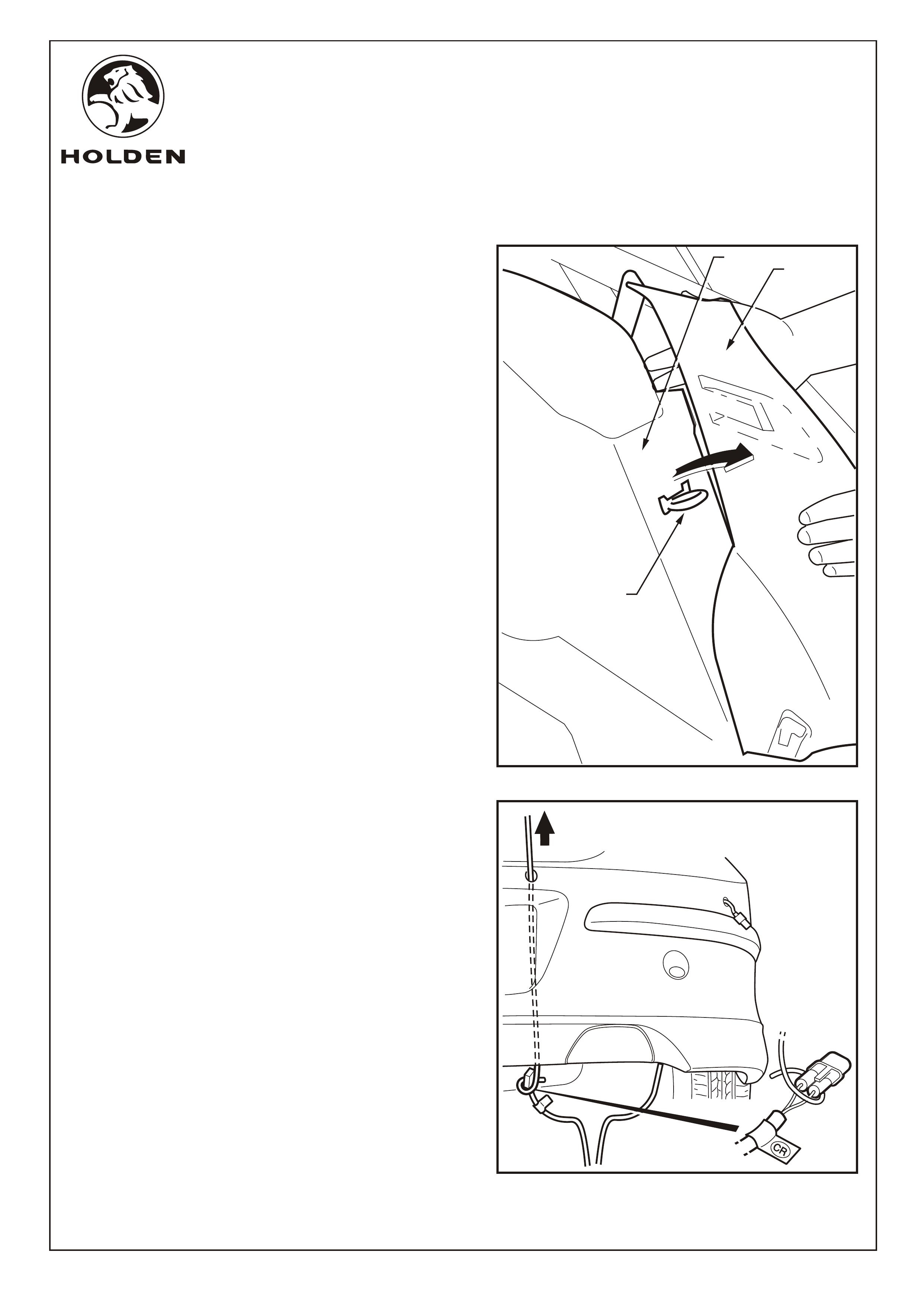
Refer to Figure 5 for the following:
6.
7. Hold back the rubber door seal (3), slide in the trim
release tool and release the clips (4) (3 places).
Disengage the “C” pillar top trim from the rear wheel arch
trim (5) and pull away.
NOTE: Do not remove the seat belt retaining bolts.
Remove the plug (1) from the “C” pillar trim (2) with the
aid of a trim removal tool.
FIGURE 3
FIGURE 5
VIEW A
2
3
4
5
A
1
1
Page 3 of 13
FD1257
05NOV04
COPYRIGHT
Reproduction in whole or part
prohibited without written approval
HOLDEN LTD
Division of HOLDEN Ltd ACN 006 893 232
FITTING INSTRUCTIONS FOR
AH ASTRA REAR PARKING SENSORS
FITTING INSTRUCTIONS: - continued...
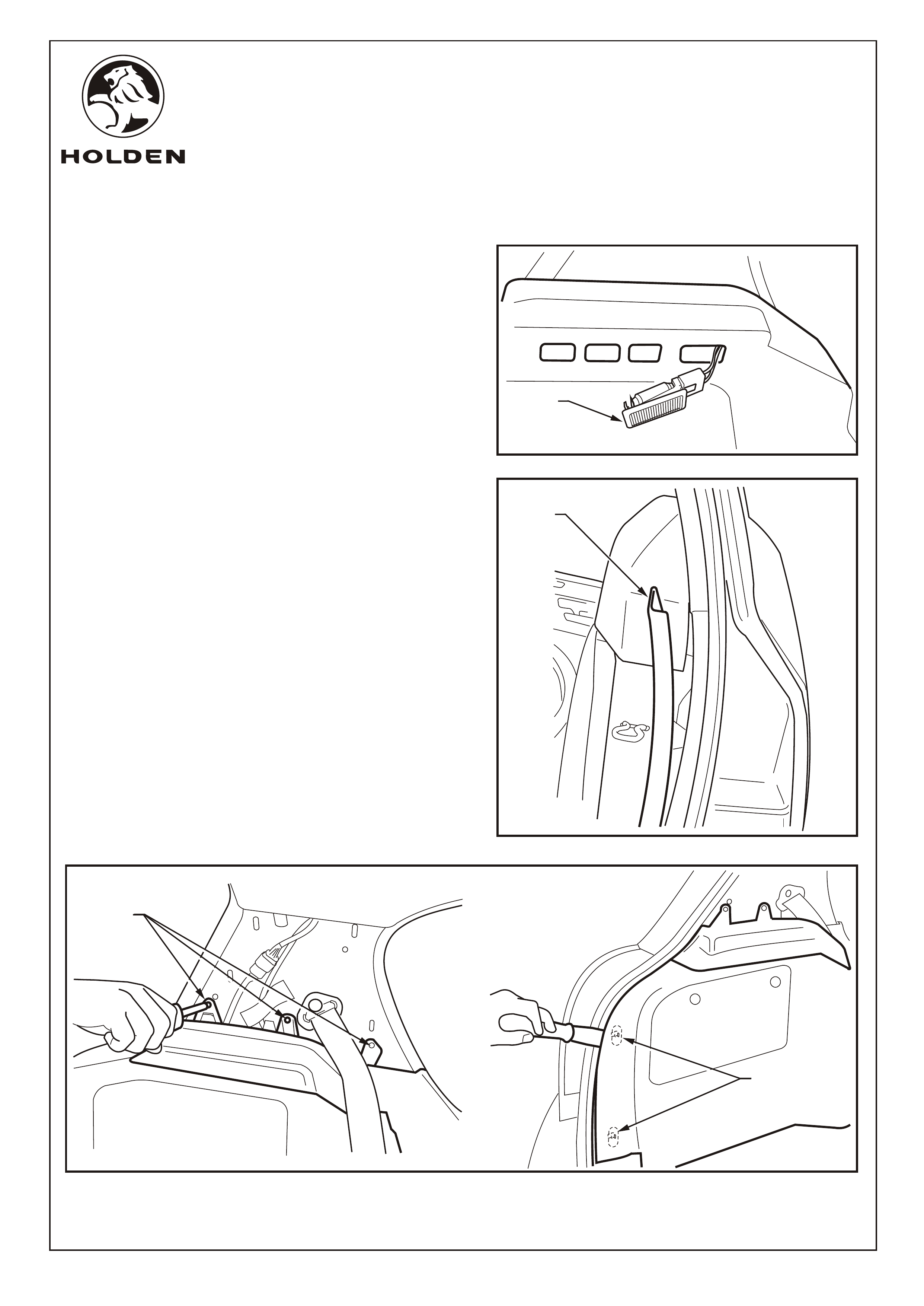
8. On the passenger's side of the vehicle remove the rear
compartment light (1) and disconnect it from the vehicle
harness. Refer to Figure 6.
9. Release the rear wheel arch trim (1) but do not remove.
Refer to Figure 7.
Refer to Figure 8 for the following:
10. Use a Torx screwdriver to remove the screws (1) (3
places) retaining the rear compartment trim.
11. Slide the trim removal tool under the side trim to release
the clips (2) around the hatch opening. Refer to Figure 8.
FIGURE 6
FIGURE 7
FIGURE 8
1
2
1
1
Page 4 of 13
FD1257
05NOV04
COPYRIGHT
Reproduction in whole or part
prohibited without written approval
HOLDEN LTD
Division of HOLDEN Ltd ACN 006 893 232
FITTING INSTRUCTIONS FOR
AH ASTRA REAR PARKING SENSORS
FIGURE 9
FITTING INSTRUCTIONS: - continued...
13. Feed the rear parking sensor (RPS) harness connectors
through the bumper fascia as follows:
a. Pass a piece of guide wire through the right-hand side
fascia hole, down between the bumper fascia and the
bumper reinforcement.
b. Fix the right hand side connector (R) to the wire and
pull back through the hole.
NOTE: Use care when feeding the connector
between the fascia and bumper reinforcement.
c. Repeat for the centre-right (CR), the centre left (CL)
and the left (L) connectors.
NOTE: Ensure the harness connectors correspond to
the position of the sensors. This is indicated by a label
situated behind the harness connector as follows:
L- Left
CL - Centre Left
CR - Centre Right
R- Right
12. Hold the wheel arch trim (1) out to give enough space to
allow the rear compartment side trim (2) to be moved
forward to clear the rear seat back retaining catch (3).
Refer to Figure 9.
Refer to Figure 10 for the following:
1
2
3
FIGURE 10
Page 5 of 13
FD1257
05NOV04
COPYRIGHT
Reproduction in whole or part
prohibited without written approval
HOLDEN LTD
Division of HOLDEN Ltd ACN 006 893 232
FITTING INSTRUCTIONS FOR
AH ASTRA REAR PARKING SENSORS
5
2
1
3
4
6
FIGURE 11
FIGURE 13
FITTING INSTRUCTIONS: - continued...
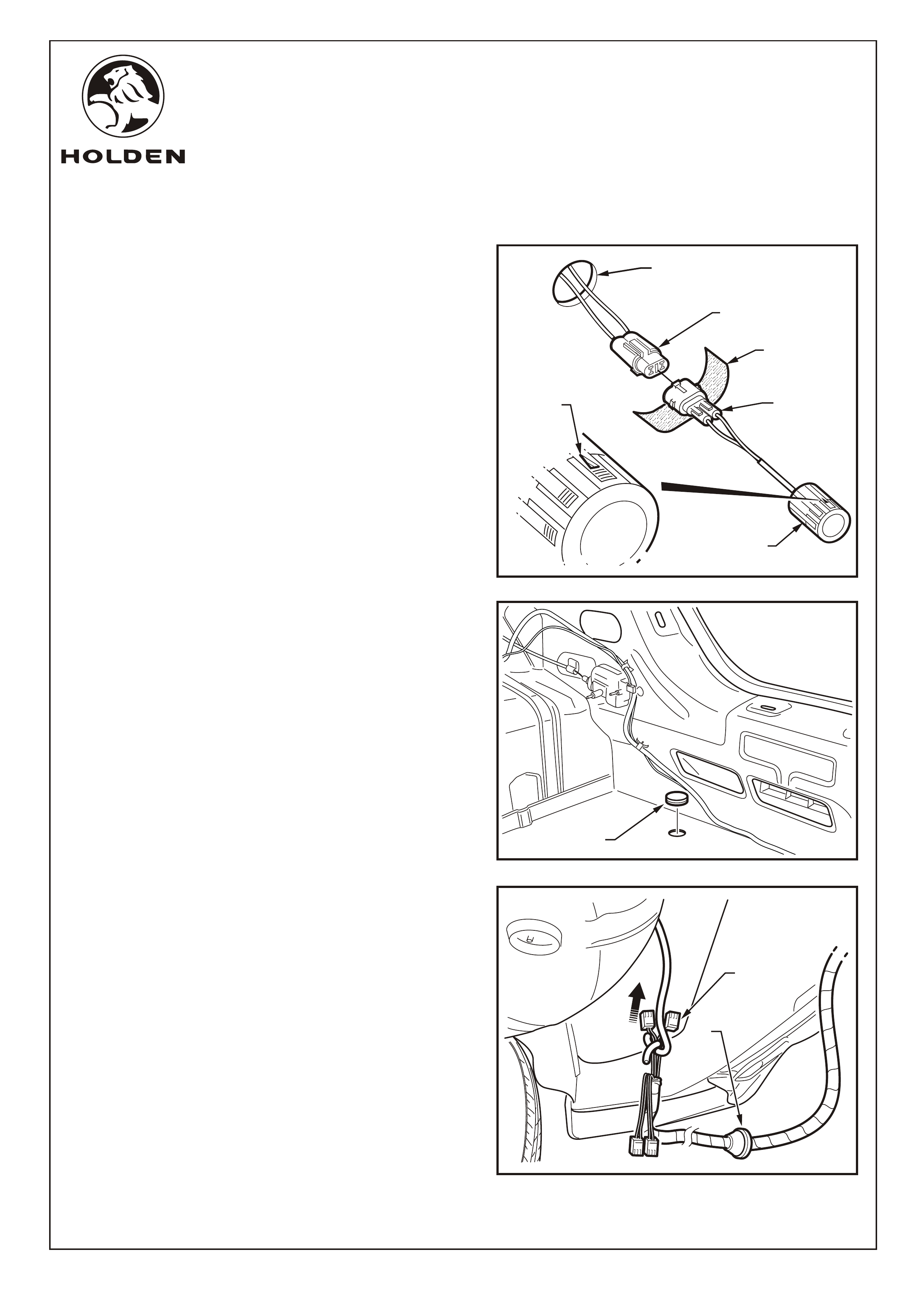
Refer to Figure 11 for the following:
14. Peel the protective backing off the foam strip (1) and
wrap firmly around the sensor connector (2).
15. Connect the sensors to the RPS harness c o n n e c t o r s
(3).
16. Pass the connectors back through the holes (4) then
press fit the reverse parking sensors (5) (4 places) into
the holes drilled in the fascia.
IMPORTANT: Ensure the arrow (6) on the sensor body is
positioned at the top of the sensor when fitted to the
fascia.
17. Remove the grommet from the rear compartment floor.
Refer to Figure 12.
18. Feed the RPS harness module connectors (1) through
the hole in the rear compartment floor and fit the
grommet (2) securely in position. Refer to Figure 13.
NOTE: Ensure that the grommet mounting hole
surround is clean and free from sealant.
FIGURE 12
1
1
2
Page 6 of 13
FD1257
05NOV04
COPYRIGHT
Reproduction in whole or part
prohibited without written approval
HOLDEN LTD
Division of HOLDEN Ltd ACN 006 893 232
FITTING INSTRUCTIONS FOR
AH ASTRA REAR PARKING SENSORS
FIGURE 14
FITTING INSTRUCTIONS: - continued...
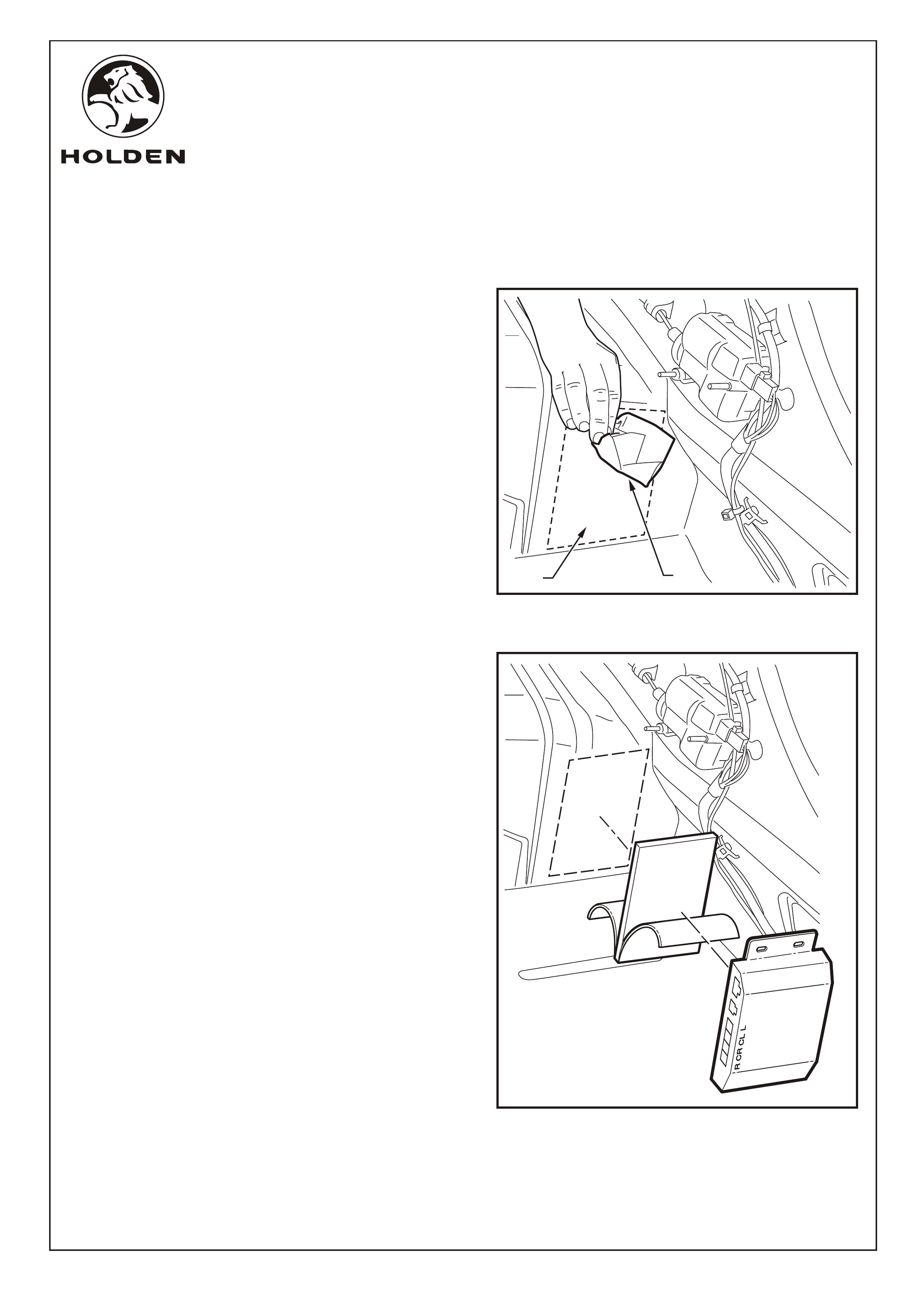
19. Clean the RPS module mounting area (1) then wipe with
the hi-tech cleaning pad (2) supplied (retain pad for later
use). Also wipe the back of the RPS module. Refer to
Figure 14.
Refer to Figure 15 for the following:
20. Peel the backing off one side of the RPS module velcro
mounting pad and press fit firmly to the back of the RPS
module.
21. Peel the backing off the remaining side of the velcro
mounting pad and press fit the RPS module onto the
inner rear quarter panel in the position indicated,
ensuring the wiring connector sockets face towards the
front of the vehicle. Apply pressure to the RPS module
unit to ensure a secure fit.
FIGURE 15
12
Page 7 of 13
FD1257
05NOV04
COPYRIGHT
Reproduction in whole or part
prohibited without written approval
HOLDEN LTD
Division of HOLDEN Ltd ACN 006 893 232
FITTING INSTRUCTIONS FOR
AH ASTRA REAR PARKING SENSORS
FITTING INSTRUCTIONS: - continued...
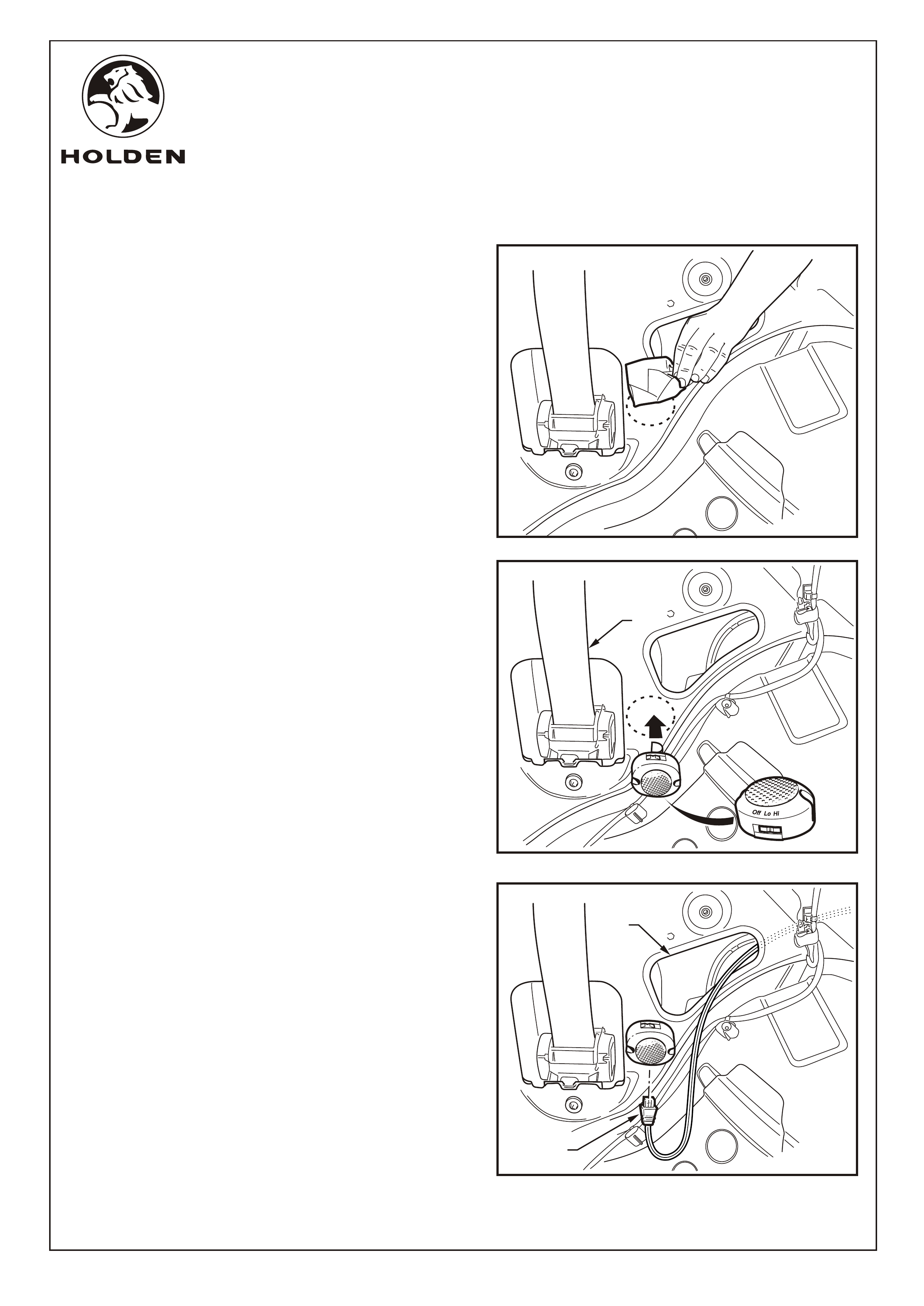
Refer to Figure 16 for the following:
22. Clean the RPS buzzer mounting area behind the RHS
rear seatbelt (1). Wipe with the hi-tech cleaning pad
supplied (retain pad for later use).
Refer to Figure 17 for the following:
23. Ensure that the RPS buzzer switch is set to 'Hi'.
24. Peel the protective backing off the RPS buzzer and
press fit in the position indicated ensuring the wiring
socket faces down. Apply pressure to the buzzer unit to
ensure a secure fit.
Refer to Figure 18 for the following:
25. Pass the connector (1) for the RPS buzzer through the
opening (2) above the wheel arch.
26. Connect the RPS buzzer harness connector to the RPS
buzzer.
FIGURE 16
OffOff
LoLo
HiHi
OffOff
LoLo
Hi
Hi
FIGURE 17
Off
Off
LoLo
HiHi
OffOff
LoLo
Hi
Hi
1
2
Page 8 of 13
FIGURE 18
1
FD1257
05NOV04
COPYRIGHT
Reproduction in whole or part
prohibited without written approval
HOLDEN LTD
Division of HOLDEN Ltd ACN 006 893 232
FITTING INSTRUCTIONS FOR
AH ASTRA REAR PARKING SENSORS
FIGURE 20
FITTING INSTRUCTIONS: - continued...
Refer to Figure 19 for the following:
27. Clean the reverse module box mounting area behind the
RHS rear wheel arch (1). Wipe with the hi-tech cleaning
pad supplied (retain pad for later use).
28. Peel the protective backing off the reverse module box
(2) and press fit in the position indicated ensuring the
wiring harness faces towards the rear of the vehicle.
Apply pressure to the reverse module box to ensure a
secure fit.
Refer to Figure 20 for the following:
29. Disconnect the lamp connector (1) from the RHS lamp
assembly (2).
30. Connect the RPS patch harness connector (3) to the
lamp connector (1).
31. Connect the RPS patch harness connector (4) to the
lamp assembly (2)
32. If a trailer harness is fitted, remove tape retaining the
connectors (5 and 6) to the RPS patch harness and
unravel the wire. Disconnect the trailer harness
connector (grey wire) (5) from the connector (6) on the
RPS patch harness. Route the wire (5) to the rear lamp
on the rear LHS.
NOTE: If a trailer harness is not fitted, then the
connectors (5 and 6) should be connected.
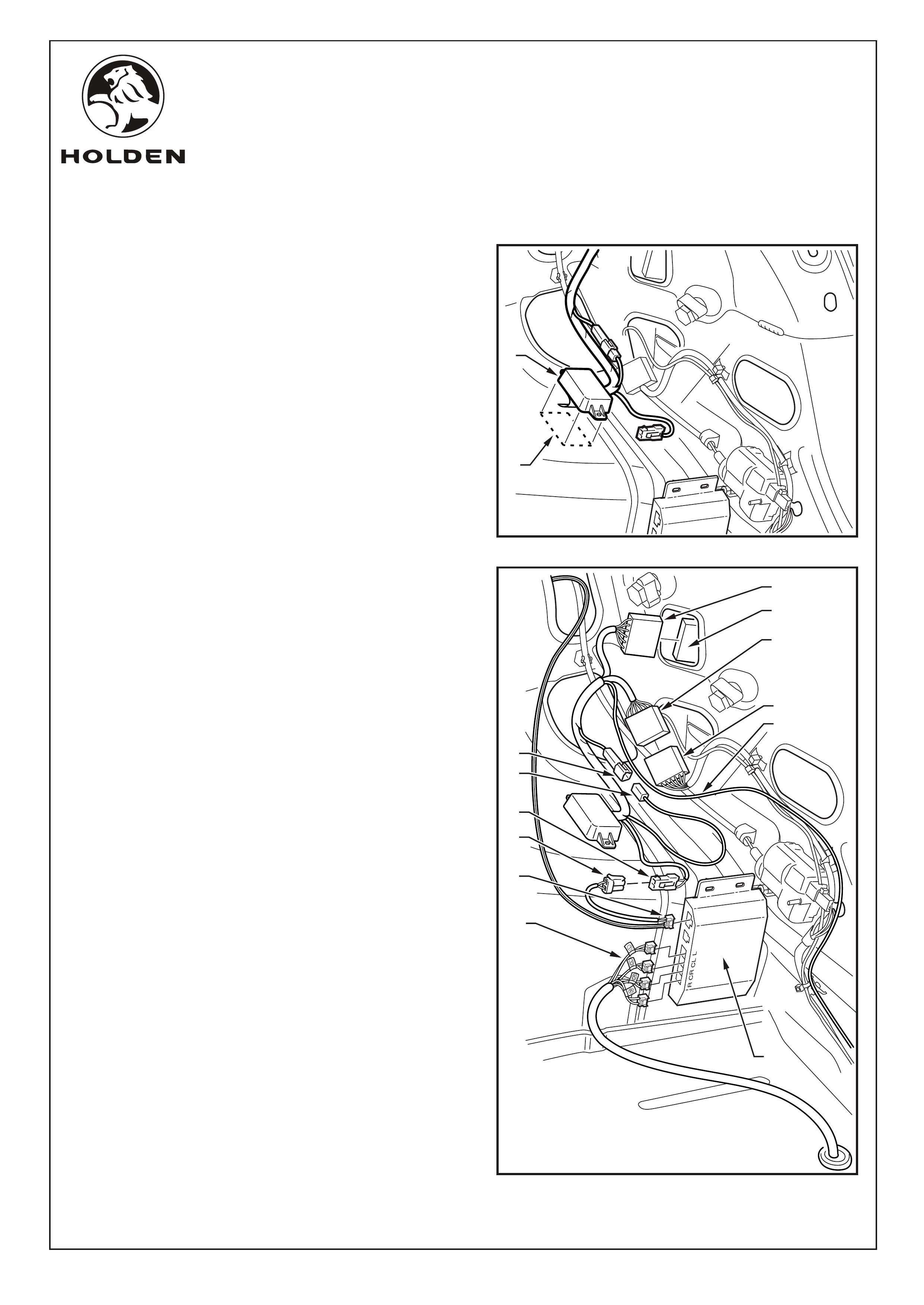
33. Connect the patch harness power connector (7) to the
connector (8) on the RPS buzzer harness.
34. Connect the RPS buzzer harness connector (9) to the
connector on the RPS module (10).
35. Connect the four RPS harness connectors (11) into the
corresponding positions on the RPS module (10). The
connectors on the RPS main harness are identified with
labels as follows:
L- Left
CL - Centre Left
CR - Centre Right
R- Right
36. Route the power connector lead (red wire) (12) to the
fuse panel on the rear LHS.
Page 9 of 13
2
6
11
FIGURE 19
4
2
3
1
12
10
9
8
7
5
6
1
2
FD1257
05NOV04
COPYRIGHT
Reproduction in whole or part
prohibited without written approval
HOLDEN LTD
Division of HOLDEN Ltd ACN 006 893 232
FITTING INSTRUCTIONS FOR
AH ASTRA REAR PARKING SENSORS
FIGURE 21
FIGURE 22
FIGURE 23
FITTING INSTRUCTIONS: - continued...
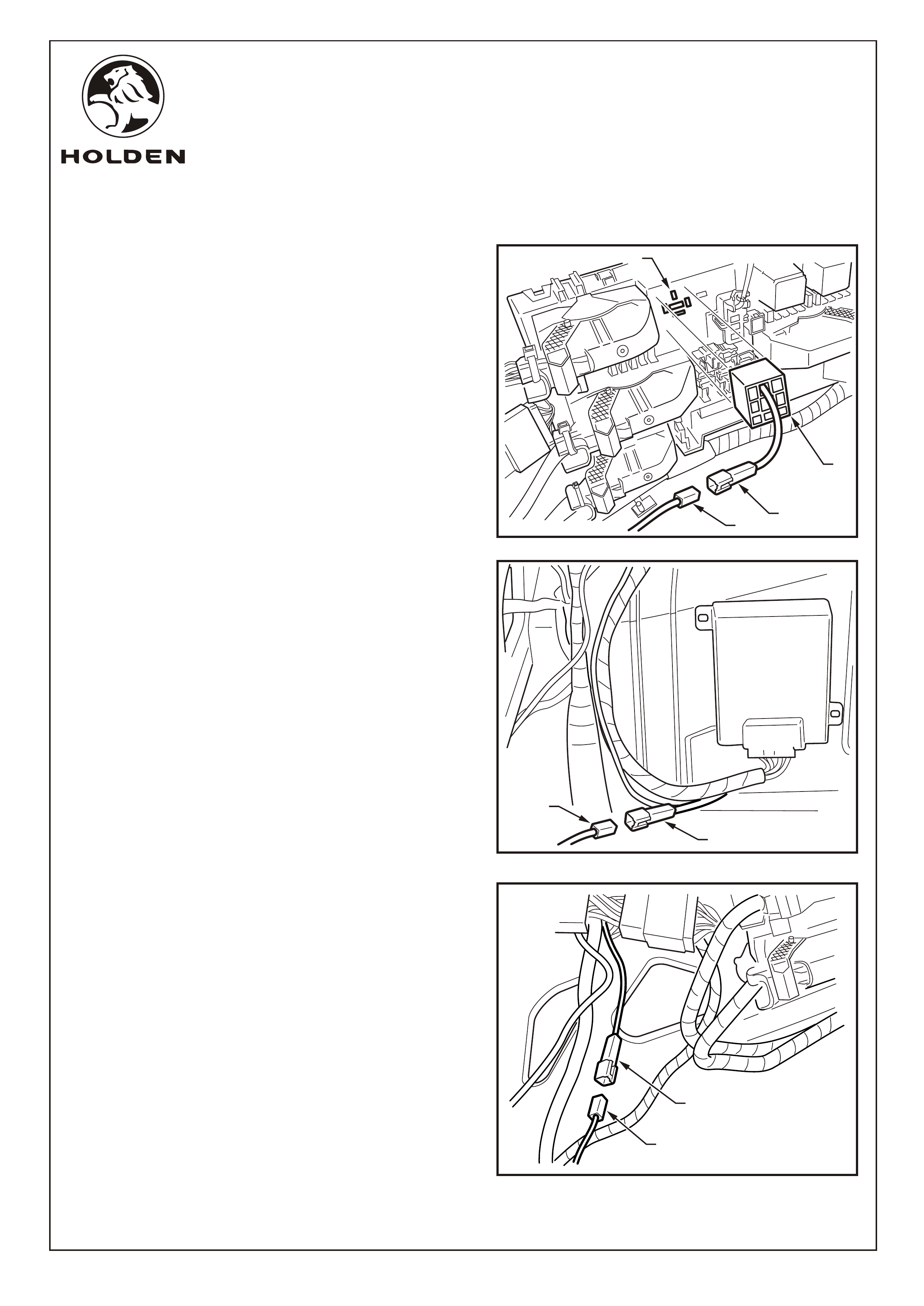
37. If a trailer harness is not fitted, connect the RPS patch
harness power connector (red wire) (1) to the power
patch harness (red wire) (2). Insert the relay base (3)
into the relay socket (4). Refer to Figure 21.
38. If a trailer harness is fitted, connect the RPS patch
harness power connector (red wire) (1) to the connector
on the trailer harness (red wire) (2). Refer to Figure 22.
39. If a trailer harness is fitted, connect the RPS trailer
harness connector (grey wire) (1) to the trailer present
signal connector (grey wire) (2). Refer to Figure 23.
12
4
3
2
1
Page 10 of 13
2
1
FD1257
05NOV04
COPYRIGHT
Reproduction in whole or part
prohibited without written approval
HOLDEN LTD
Division of HOLDEN Ltd ACN 006 893 232
FITTING INSTRUCTIONS FOR
AH ASTRA REAR PARKING SENSORS
FITTING INSTRUCTIONS: - continued.
40. Neatly cable tie excess wiring harness.
41. Locate a suitable position for the caution label (e.g. B-
Pillar). Clean the area using the hi-tech cleaning pad.
Attach the caution label.
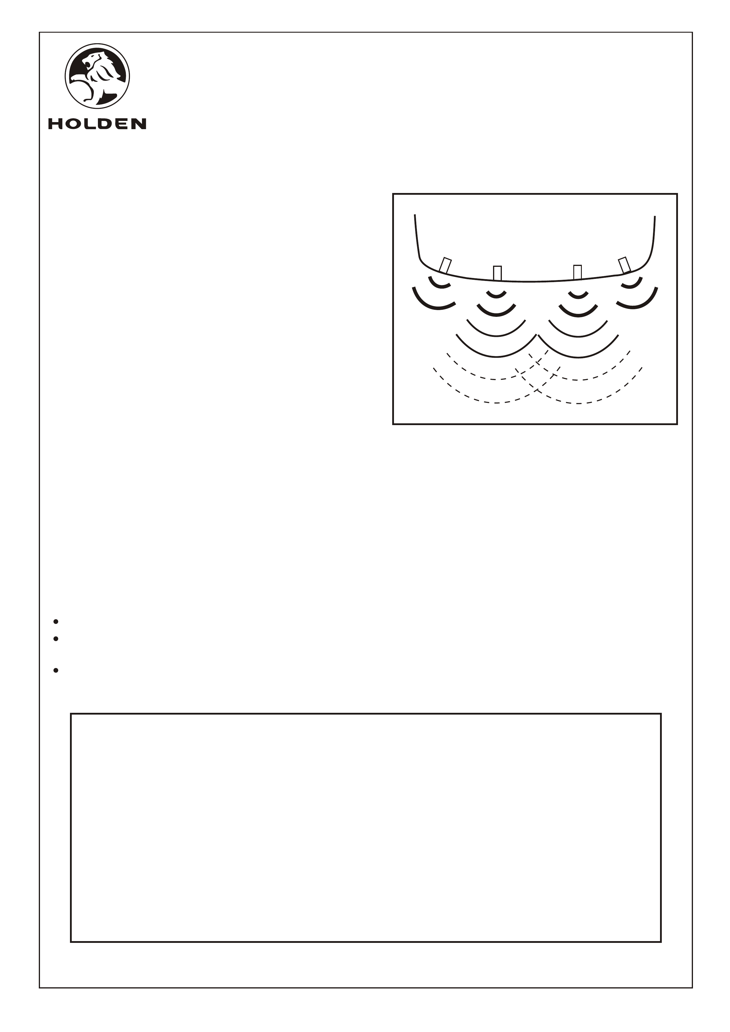
42. Test the reverse parking sensor system for correct
operation as follows:
Turn the ignition to the "ON" position (engine not
running).
Place the gear lever in reverse (R).
From behind the vehicle, walk towards each sensor.
The two centre sensors have 3 stages.
The two corner sensors only have 1 stage of final
warning. Refer to Figure 24.
Refer to the RPS owner's manual for further
information and trouble shooting.
Turn the ignition to the "OFF" position.
43. Refit all removed parts and torque fasteners to
specifications.
44. Place the fitting instructions in the glovebox.
IMPORTANT:
DO NOT paint over the reverse parking sensor.
Ensure the reverse parking sensor remains clean
and free from road grime, mud, car polish etc.
If the sensor or the groove on the sensor surface
becomes contaminated, the performance may be
affected.
Ÿ
Ÿ
Ÿ
PARTS LIST
PART NUMBER DESCRIPTION QUANTITY
92148370 REAR PARKING SENSOR KIT 1
SENSOR HEAD 4
FOAM STRIP 4
RPS SENSOR HARNESS 1
RPS PATCH HARNESS 1
RPS SPEAKER 1
RPS SPEAKER HARNESS 1
RPS CONTROL MODULE
VELCRO PAD 1
POWER PATCH HARNESS 1
CABLE TIE 12
ALCOHOL WIPE 1
REAR PARKING SENSOR OWNER'S MANUAL 1
FD1257 FITTING INSTRUCTIONS 1
FD796 PROOF OF WARRANTY CARD 1
Page 11 of 13
FIGURE 24