Audio Installation Guide - 2001 Widetrack Jackaroo
ATTACHMENT TO ENGINEERING BULLETIN _______________
Eurovox Kit: 92074702 Page: 1 of 5
AUDIO KIT
KIT CONTENTS:
ITEM EUROVOX PART NUMBER
1.
RADIO CASSETTE MOD4685IS1
2.
RADIO HARNESS WIS32
3.
SPEAKERS 4” - REAR DOORS (2) 2042/BL
4.
SPEAKERS 4” - REAR (2) ETS502CX
5.
SPEAKERS 6” - FRONT DOORS (2) 2067C/BL
6.
GRILLES 4” – REAR DOOR (2) ESG40-B/BL
7.
ANTENNA MODAW01
8.
HANDBOOK HPB-4685I
EXTRAS:
CABLE TIES STD (6) 6mm NUT (1)
10g x ¾” SCREWS (8) SECURITY CODE CARD (1)
INSTALLATION PROCEDURES:
NOTE: Fit 20 AMP audio fuse before commencing (Position C15)
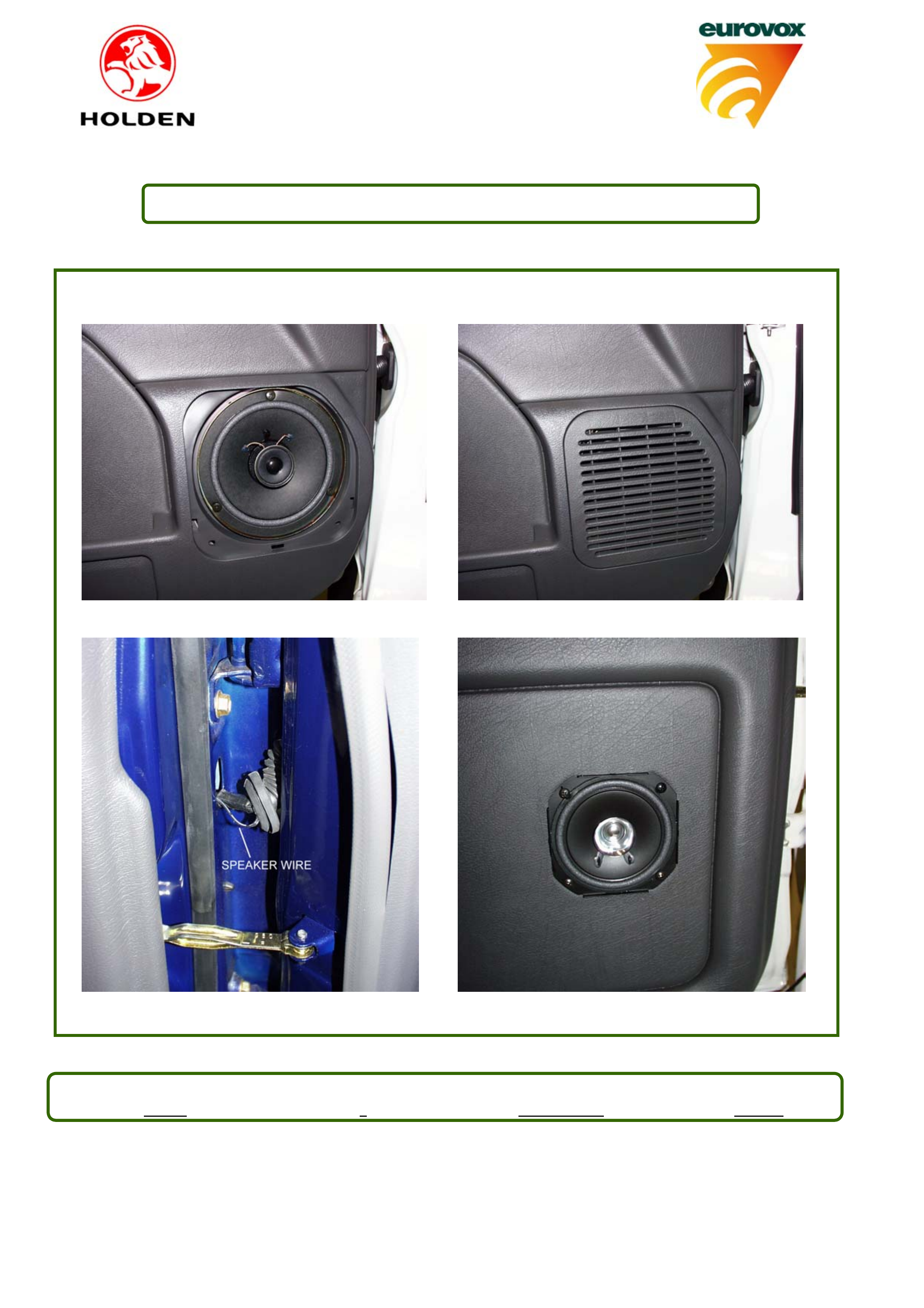
FRONT DOOR SPEAKERS
1. Remove door speaker cover (via clips) and speaker blank (3 screws). Discard blanking plate.
2. Locate vehicle harness and plug into speaker. Mount 6” speaker, using original screws [Fig A] and
refit door cover [Fig B]. Repeat for other front door.
REAR DOOR SPEAKERS
3. Remove front and rear floor sill panels and kick trim.
4. Remove door seal rubbers from centre pillar cover and remove cover [clips].
5. Using template provided, mark speaker locations and cut speaker hole.
FOR MODEL 8DQ 35
Remove grommet seals and use grommets provided between door and body.
6. Feed speaker lead through hole in centre pillar and into door via cable grommet [Fig C] to speaker
hole. Cut hole at door end of grommet. NOTE: Ensure that wires feed behind window guide.
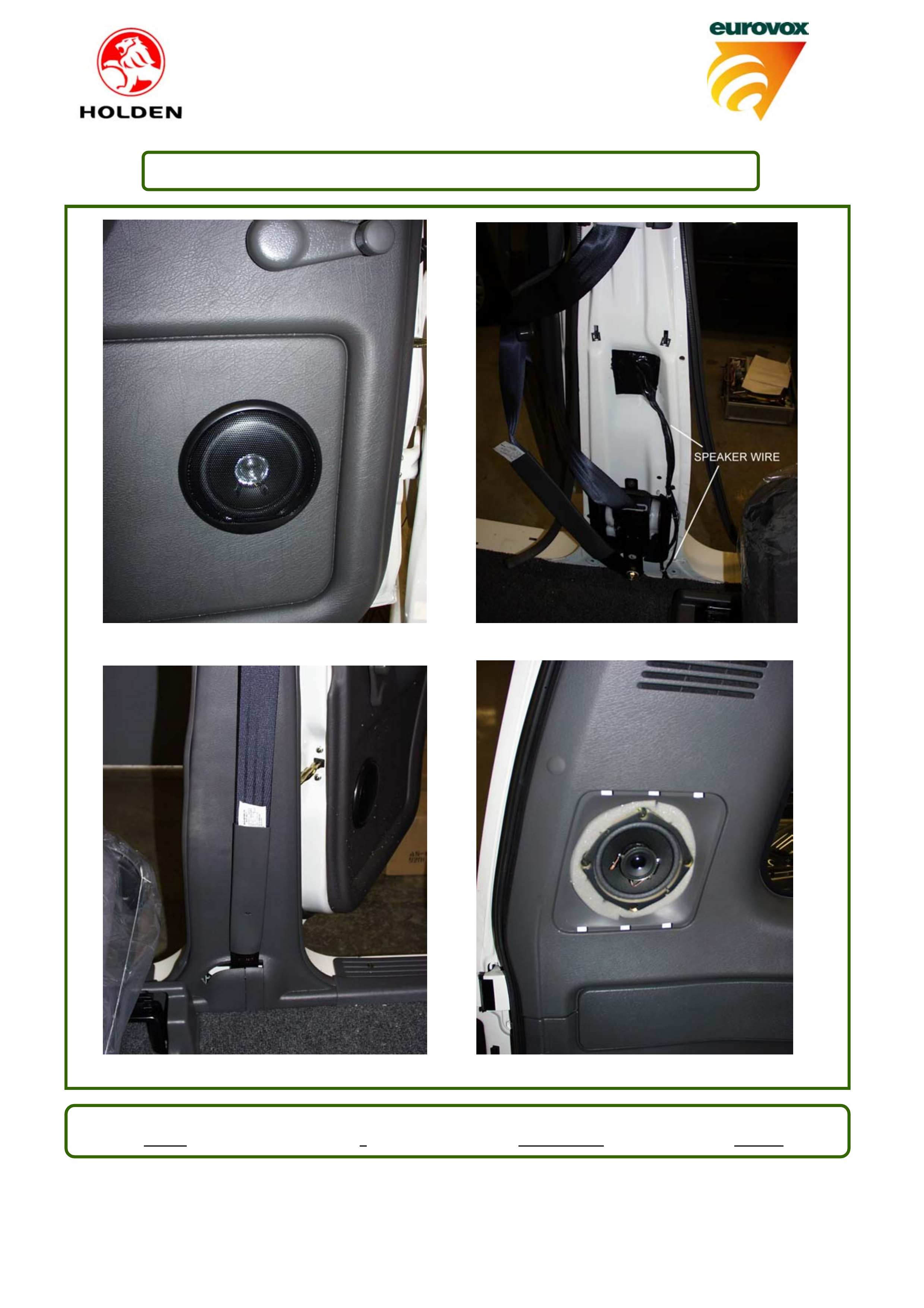
7. Connect wires to speaker and mount speaker using 4 screws provided [Fig D]. Fit speaker grille.
[Fig E].
8. Feed wires from centre pillar to floor (cable tie to existing wiring)[Fig F]. Continue under carpet to
kick panel.
9. Refit centre pillar cover, door seals, floor sill panels and kick trim [Fig G]. Leave passenger side kick
trim off.
10. Repeat for other door
Eurovox No. Issue No. Authorised Date
EIG151 1Colin Moreland 10/12/01

Audio Installation Guide
Kit No. 92074702 Page: 2 of 5
REAR SPEAKERS
11. Remove speaker cover (via clips) and speaker blank (4 screws). Discard blanking plate.
12. Locate vehicle harness and plug into speaker. Mount 4” speaker, using original screws [Fig H] and
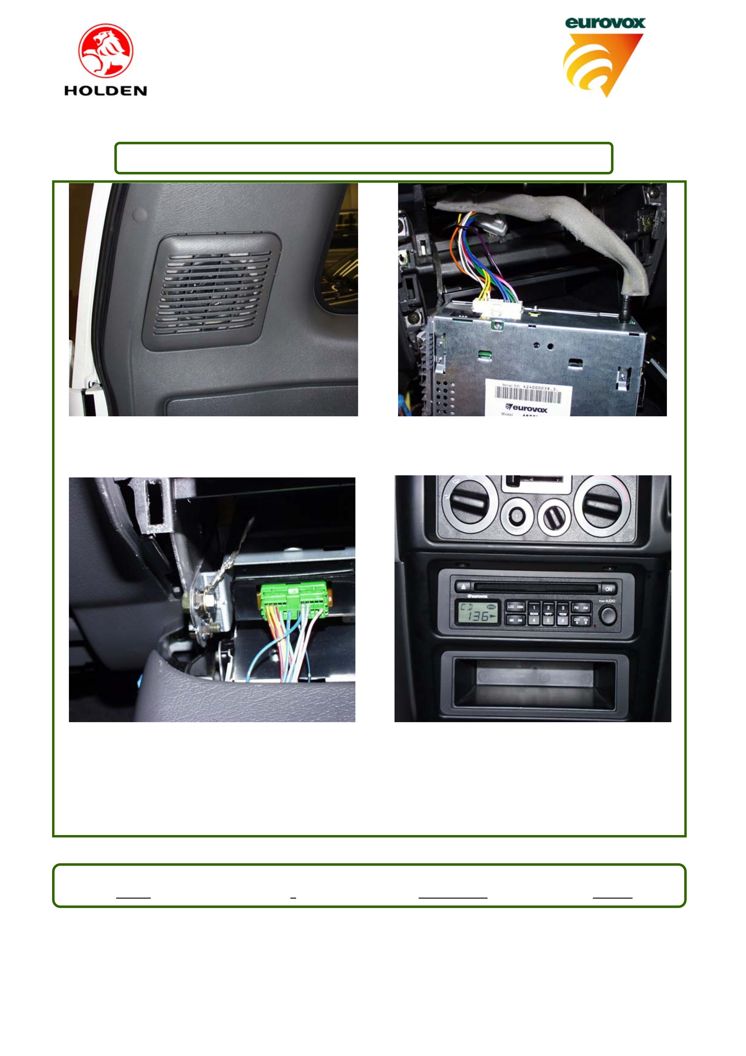
refit cover [Fig I]. Repeat for other speaker.
ANTENNA
13. Fully turn wheel to left lock.
14. Remove inner guard liner.
15. Remove head kit from antenna, leaving aluminium base plate.
16. Mount antenna to guard making sure to assemble antenna head kit exactly as it was supplied.
17. Remove grommet and discard. Feed antenna lead through hole and fit grommet.
18. Connect antenna lead to antenna fly lead located in front left kick panel.
19. Refit inner guard.
20. Place antenna “whip” mast in rear cargo area of vehicle.
21. Remove centre console (4 screws).
22. Remove radio surround (3 screws and clips).
23. Remove top pocket (2 screws) and discard pocket.
RADIO
24. Locate vehicle harness and antenna lead. Connect radio harness to vehicle harness. Feed speaker
wire (yellow wire connection) to drivers side and connect to rear door speaker lead. Cable tie
speaker lead to existing wiring in 2 positions.
25. Feed speaker wire (blue wire connection) to passenger side and connect to rear door speaker lead.
Cable tie where necessary.
26. Plug radio harness and antenna lead into rear of unit (Fig.J) and mount unit using original pocket
screws. Ensure that earth lead feeds behind and below bottom pocket. Connect earth lead to bolt
using 6mm nut provided. (Fig.K)
27. Refit radio surround. Refit centre console [Fig.L].
28. Enter security code and test all functions.
Eurovox No. Issue No. Authorised Date
EIG151 1Colin Moreland 10/12/01
Audio Installation Guide
Kit No. 92074702 Page: 3 of 5
FIGURE A FIGURE B
FIGURE C FIGURE D
Eurovox No. Issue No. Authorised Date
EIG151 1Colin Moreland 10/12/01
Audio Installation Guide
Kit No. 92074702 Page: 4 of 5
FIGURE E FIGURE F
FIGURE G FIGURE H
Eurovox No. Issue No. Authorised Date
EIG151 1Colin Moreland 10/12/01
Audio Installation Guide
Kit No. 92074702 Page: 5 of 5
FIGURE I FIGURE J
FIGURE K FIGURE L
Eurovox No. Issue No. Authorised Date
EIG151 1Colin Moreland 10/12/01