
CRUISE CONTROL
HOLDEN JACKAROO DIESEL
DRIVE BY WIRE
Part No. 92143149
PLEASE READ THESE INSTRUCTIONS THOROUGHLY BEFORE BEGINNING THE
CRUISE CONTROL INSTALLATION.
As the vehicle is fitted with an Airbag, it must be disabled before beginning installation of the cruise control. To disable
the SRS system follow the following procedure.
WARNING: FAILURE TO FOLLOW THE PROCEDURES COULD RESULT IN POSSIBLE AIR BAG DEPLOYMENT,
PERSONAL INJURY OR OTHERWISE UNNEEDED SRS REPAIRS.
The SDM in the SRS can maintain sufficient voltage to cause a deployment for up to 15 seconds after the ignition
switch is turned “OFF”, the battery is disconnected, or the fuse powering the SDM is removed.
Disabling the SRS
Turn the ignition switch to “Lock” and remove the key.
1. Disconnect the battery.
2. Disconnect the yellow 3-pin connector at base of steering column.
Enabling the SRS.
Turn the ignition switch to “Lock” and remove the key.
1. Connect yellow 3-pin connector at base of steering column.
2. Connect battery.
Check over the parts provided in this kit before you begin and be aware of where you are going to use them.
This kit contains the following:-
1. 1 x Main Wiring Harness – AUT-JACK/99
2. 1 x Drive by Wire Patch Harness – AUT-JACK/DBW
3. 1 x Command Switch Harness – AUT-HW100/U
4. 1 x Dash “Cruise Control ON” indicator
5. 1 x Cruise Control Steering Wheel Switch.
6. 2 x Cruise Control Switch Support Bracket.
7. 2 x M3x6mm PT screws.
8. 1 x Drive by Wire Interface Module (mounted on bracket).
9. 1 x Cruise Control Module.
10. 2 x “U” Brackets with Speed Nuts
11. 4 x Philips 8g x 12mm screws.
12. 1 x Clutch Switch — P/N 8-94362930-0
13. 6 x 150mm cable ties
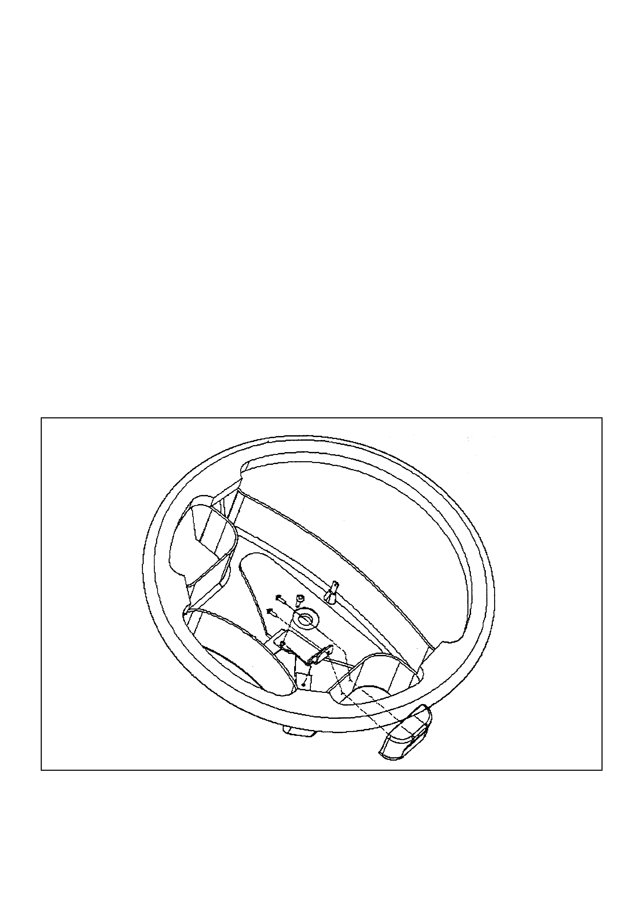
Steering Wheel Command Switch Installation
1. After disabling Air Bag remove air bag assembly.
2. Install cruise control switch support bracket as shown in diagram 1
3. Using the mounting hole in the support bracket as a guide, drill a 3.5mm hole in the steering wheel.
4. Temporarily fit the cruise control switch with one of the M3 x 6mm PT screws. Remove the cover from the cruise
control command switch by sliding it away from the buttons and use the second mounting hole in the switch to
mark where to drill the top-mounting hole, also mark the centre of the large hole for the wiring.
5. Remove the switch and drill the top-mounting hole on your mark with a 3.5mm drill & the large hole for the wiring
at 8mm.
6. Attach the switch using the two PT screws provided.
7. Route the small white connector of the wiring harness through the 8mm hole and connect to the connector on the
P.C.B of the Command switch.
8. Unplug the horn wiring connector in the steering wheel (1 way white connector with yellow anti-back out) and
connect the bridge connector in using the correct mating connectors of the harness. Cut off or tape back the spare
connectors, which are not used.
9. Connect the earth eye terminal of the black wire to a screw in the steering wheel.
10. Re-install the air bag assembly.
NOTE: PRESSING THE CRUISE CONTROL BUTTONS AT THIS TIME WILL CAUSE THE HORN TO OPERATE,
THIS IS NORMAL UNTIL THE INSTALLATION IS FINISHED.
Diagram 1
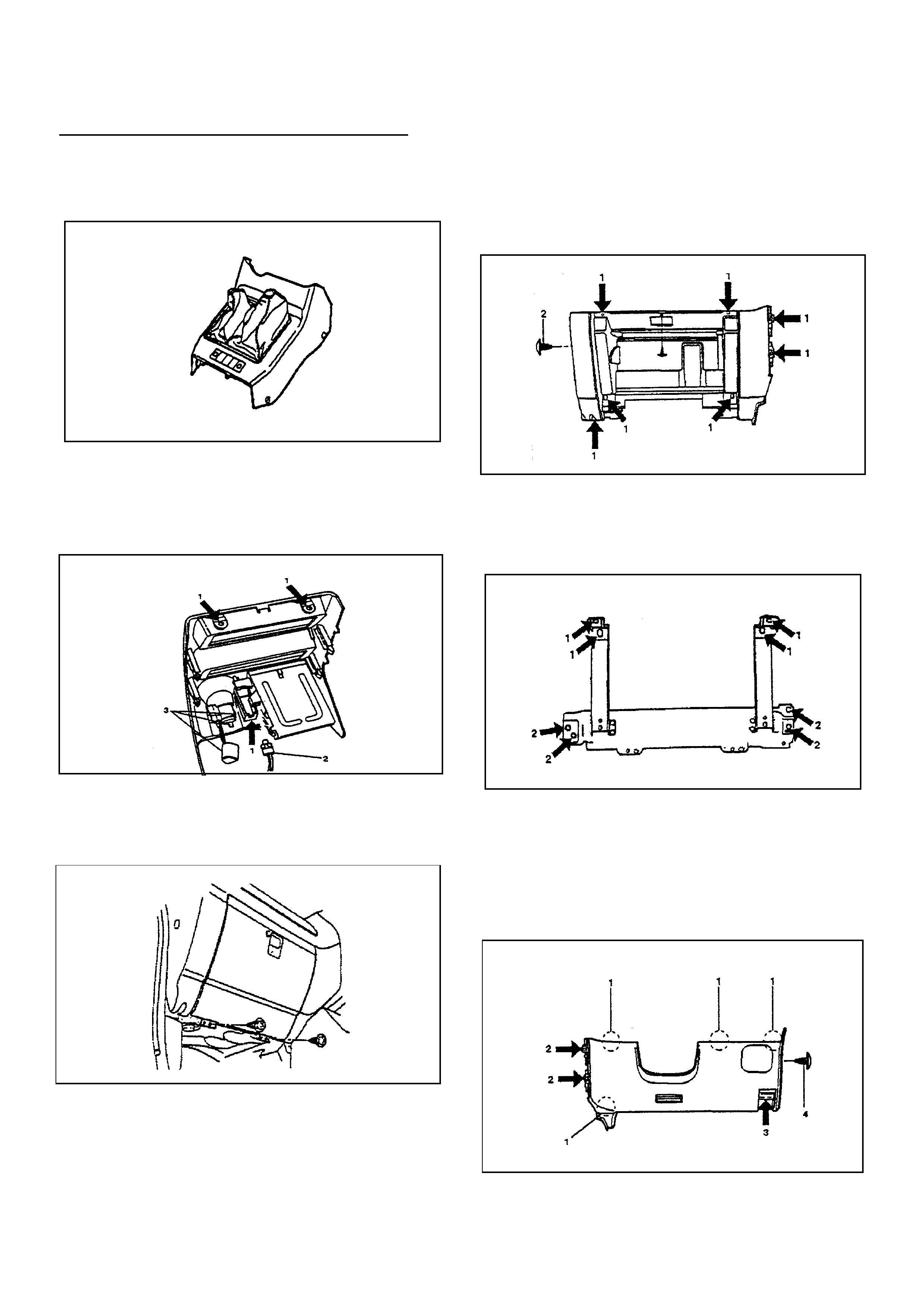
Electronic Modules & Main Harness Installation
1. Remove screws from the front section of the center
console and lift up and back out of the way.
2. Remove the 3 fixing screws (1) from the radio
surround, disconnect the cigarette lighter (3) and
the illumination (2) connectors from the radio
surround and remove.
3. Remove the two screws from the hinges of the
glove box and remove glove box.
4. Remove the lower dash trim passenger side.
Remove the 7 fixing screws (1) and the clip (2),
taking care when removing the clip from the end of
the dash.
5. Remove the Passenger knee bolster reinforcement
assembly by removing the 4 fixing blots (2) and the
4 nuts (1).
6. Remove instrument panel drivers side cover
assembly. First remove the engine hdod opener
fixing screws. Remove the 2 fixing screws (2), 1
fixing bolt (3), and 1 clip (4). Pull out the fasteners at
the positions (1).
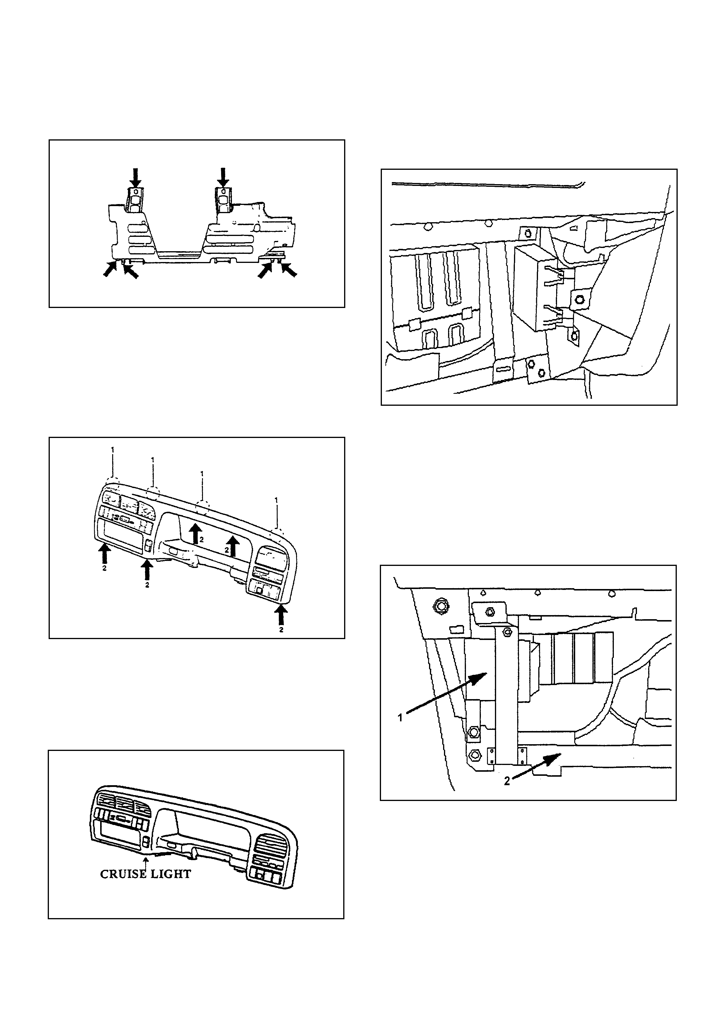
7. Remove drivers side knee bolster assembly by
removing the 6 fixing nuts.
8. Remove the passenger side kick trim.
9. Remove the instrument panel cluster surround by
removing the 5 fixing screws (2) and pull the main
unit towards you and remove the clips at the 4
positions (1). Disconnect the switch connectors.
10. Remove the single dash blank to the left of the
steering wheel and below the row of switches. This
is the blank that is in the position of the factory
Cruise Control On/Off switch. Install the new
"Cruise Control ON” indicator in the position shown.
11. The Cruise Control electronics module is mounted
using the two V brackets & screws to the Anti-Theft
Module, it is located on the passenger side of the
center console.
12. The second module is the Drive by Wire interface
module. This module is fitted in the position as
shown in diagram (1). The mounting bracket fits on
the two points as shown in the diagram after routing
the wiring harness refit the Passenger knee bolster
reinforcement to hold this module in place. Note
you will need to re-locate the electric aerial module
to the lower vertical portion bracket as shown (2).
13. Route the wiring harness supplied as follows, care should be taken when routing behind the centre
console that the wiring is not damaged by any sharp edges of the metal work.
a. The 22-way junction connects to the white 22-way connector located in the passenger kick trim.
b. The 6-way connector connects to the 6-way of the Drive by Wire patch harness.
c. The 14-way junction of the Drive by Wire patch connects to the 14 way that is located to the left the heater fan
under the dash on the passenger side.
d. The 20-way plugs into the Cruise Control Main electronics module (NOTE:the horn may operate as you plug in the
20-way connector into the Cruise Control Module, this is normal).
e. The earth ring terminal is to be placed under one of the M6 nuts which holds the Anti-Theft Module bracket.
f. The 3-way housing is for the "Cruise Control ON” indicator on the instrument surround.
g. The 14-way junction with 12 small and 2 large terminals connects to the same type of housing located under the
steering column. This is the wiring coming from the blinker and headlight switch.
h. The 8-way junction connects to the 8-way connector in the ignition switch wiring under the steering column.
i. The 2-way junction connects into the wiring of the brake switch.
j. The 2-way connector taped to the harness with yellow tape is for a clutch switch on manual vehicles.
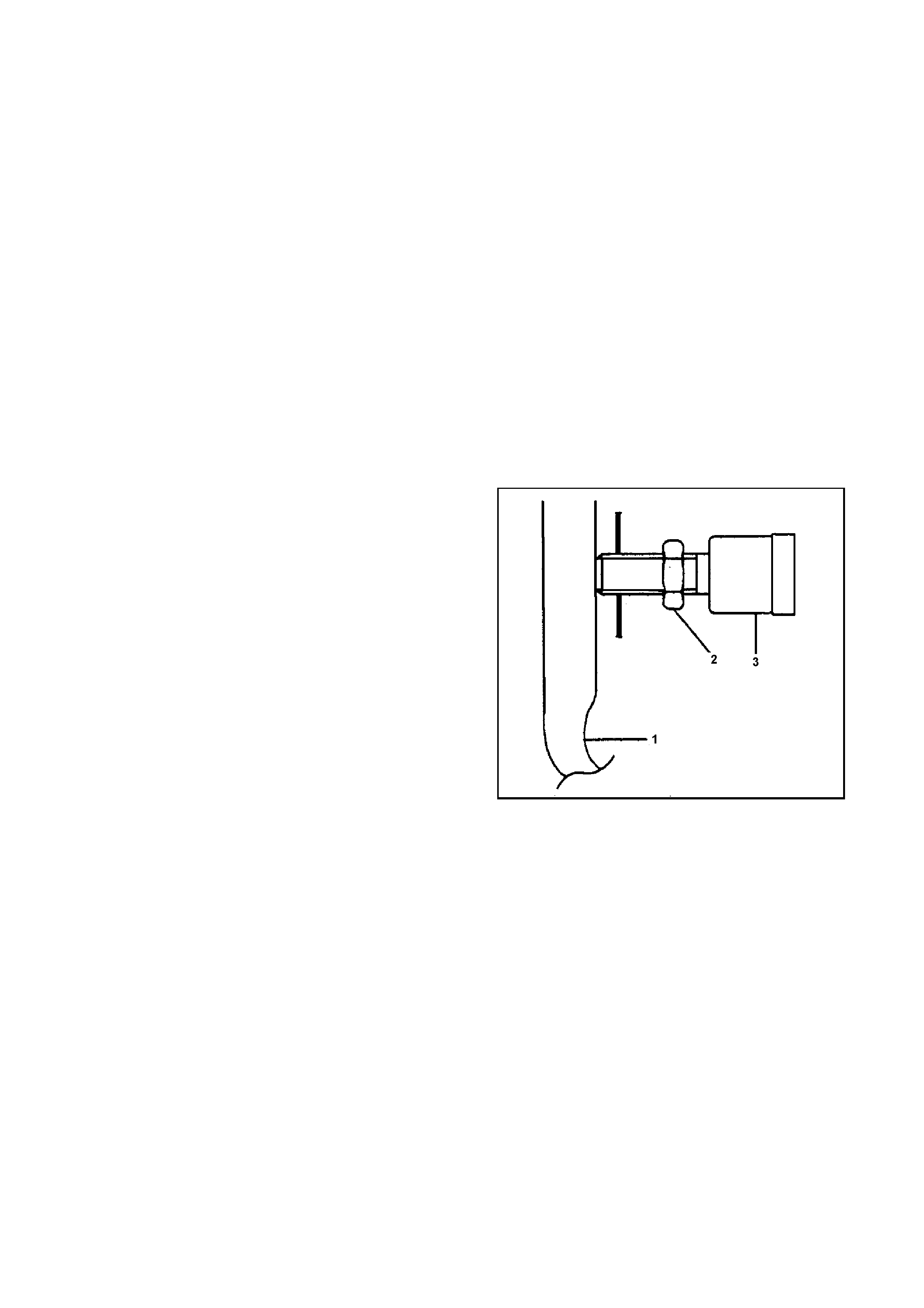
14. If the vehicle is a manua,l fit the switch supplied
{PN: 8943629300} onto the clutch pedal.
a. Remove the pedal stop bolt from the clutch pedal.
b. Check to be sure that the clutcb pedal (1) has been
completely, returned by the return spring.
c. Screw the switch in by hand until the push rod
cannot be seen from the tip portion of the switch (3).
d. Give the switch one reverse rotation.
e. Tighten the lock nut (2).2 3
f. Unplug the spare connector {taped to the harness
with yellow tape} from the bridging connector.
g. Plug it into the clutch switch.

Checking the System Operation
This cruise control is equipped with a built in Diagnostic Mode which allows you to verify that all your connections are
made correctly and that each part of the Cruise Control is functioning properly. Before reassembling the dash use this
test procedure to confirm your installation. Check over your installation one or more times to verify all connections are
secure and that all wire are correctly plugged in and cable tied in place. Put the vehicle in park, or neutral, and make
sure you have the hand brake “ON”.
To enter diagnostic mode, follow this Sequence
• Turn the ignition switch OFF.
• Press and hold the “SET” button while you turn the ignition switch ON without starting the engine.
• (The “Cruise Control ON” indicator will come on “RED”)
• Release the “SET” button.
• Press the “ON/OFF” button to turn the Cruise Control “ON”
• (The “Cruse Control ON” indicator will change to “GREEN”).
1. Note the “Cruise Control ON” indicator on the dash as well as the diagnostic LED on the cruise control electronics
module will both now respond to the following tests.
2. Turn the ”ON/OFF” switch OFF and then back ON, the “Cruise Control ON” Indicator will change colour & the
diagnostic LED should light.
3. Press and release all the switches on the steering wheel command switch. The “Cruise Control ON” Indicator
will change to orange & the diagnostic LED should light each time a switch is pressed and go out when the switch
is released.
4. Press and release the brake pedal. The “Cruise Control ON” Indicator will change to orange & the diagnostic
LED should light each time a switch is pressed and go out when the switch is released.
{If you hold down the brake pedal for an extended period the lights will also go out}.
5. For manual Transmissions press and release the Clutch pedal {this test is only if you have fitted a switch to the
Clutch pedal}. The “Cruise Control ON” indicator will change to orange & the diagnostic LED should light each
time the pedal is pressed and go out when the pedal is released {if you hold down the clutch pedal for an extended
period the lights will also go out}.
6. For Automatic Transmissions shift the selector lever from park to reverse through neutral back to park, you
should see the {Cruise Control ON” Indicator change to orange & the diagnostic LED should light and go out as
you do this. When you return to neutral it will take a moment for the LED’s to go out as they will need to time out as
this circuit is still sensing the neutral position.
7. Turn the ignition to the OFF position and press the hold and “SET” button again while you turn the ignition key ON
but this time start the engine. Release the “SET” button when the engine starts.
8. Press and hold the “ACC” switch. In a few seconds, the engine RPM should begin increasing. Release the “ACC”
switch and the engine RPM should remain constant. Press and hold the “DEC” switch. The engine RPM should
slowly decrease until it returns to idle.
9. Press and hold the “ACC” switch again. In a few seconds, the engine RPM should begin increasing. Release the
“ACC” switch and the engine RPM should remain constant. Pressing the brake release will release the cruise
control immediately and the engine should return to idle.
10. If you wish to check that the cruise control is getting a speed signal drive the vehicle. At speeds above 15 KPH the
“Cruise Control ON” indicator will blink orange then green & the diagnostic LED should flash. The rate should
increase as speed increases.
11. Turn off the ignition switch to exit diagnostic mode. The Cruise Control will automatically reset to normal operation
the next time the ignition is switched on.
12. The Cruise Control has been factory calibrated and is now ready for a test drive to confirm its operation.
13. Refit the dash trims and rearm the SRS system following instructions on the first page of these instructions.
14. You should now test drive the Cruise control and check its functions using the Operation Manual as a guide.