Instruction No. 09-17382
19/06/2001
Air Conditioning Fitting Instructions (6VD1 Models)
2001 Rodeo
V6
(Including LT Sport)
Kit No. 92144363 (4 x 2 & 4 x 4) AS-36-GR60P
Division of GM Holden Ltd
ABN 84 006 893 232

CONTENTS
PREPARATION
POINTS TO CHECK
INSTALLATION PRECAUTIONS
LABELS
SPECIFICATIONS
TIGHTENING TORQUES
PARTS TO BE REMOVED (INTERIOR)
AIR CONDITIONER SWITCH INSTALLATION
EVAPORATOR INSTALLATION
EVAPORATOR DRAIN HOSE INSTALLATION
PARTS TO BE REMOVED (ENGINE COMPARTMENT)
COMPRESSOR MOUNT INSTALLATION
COMPRESSOR INSTALLATION - PART ONE
CONDENSER FITMENT
FDR BRACKET, FDR AND
PRESSURE SWITCH WIRING INSTALLATION
DISCHARGE AND SUCTION HOSE INSTALLATION
COMPRESSOR INSTALLATION - PART TWO
COMPRESSOR CLUTCH CONNECTOR
COMPRESSOR DRIVE BELT INSTALLATION
LIQUID TUBE INSTALLATION
RELAY INSTALLATION
WIRING DIAGRAM
EVACUATION AND CHARGING PROCEDURE
3
Preparation
Before starting the installation, read these
fitting instructions through, then follow the
sequence from Page 1 through to the
evacuation and charging procedure.
Points to check
a. Check and note any damage to the
vehicle interior or exterior.
b. Check and note operation of all
accessories, horn, lights, etc.
c. Check operation of engine cooling
system.
d. Inspect the kit for damaged parts
before starting the installation.
Installation Precautions
a. This system has been designed to suit
standard wiring by the vehicle manufac-
turer, the wiring of non-approved
accessories could result in malfunction
of the unit or damage to the vehicle.
b. Disconnect the negative lead from
the battery.
c. Route all refrigerant hoses, tubes
and wiring harnesses to avoid fouling.
d. To prevent entry of moisture or foreign
material into the system do not remove
shipping plates or plugs until
immediately before installation of
components.
SIZE TUBE THREAD TORQUE
O.D. -UNF N.M.
No. 5 5/16 9/16-18 13-15.0
No. 6 3/8 5/8-18 11.0-16.0
No. 8 1/2 3/4-16 18.0-23-0
No. 10 5/8 7/8-14 24.0-30.0
No.12 3/4 1-1/6-12 30.0-38.0
Note: This system uses a
specific Lubricating oil-
Polyalkylene Glycol (PAG). This oil
is highly hygroscopic, adhere
to Step D
e. O-Rings do not require lubrication as
they are pre-fitted to most tubes/hoses
and pre-lubricated with silicon at the
manufacturer.
f.
Use two spanners when tightening fittings.
g. Use torques specified.
h. As this R134a Air Conditioning system
uses no sightglass in the filter drier,
refrigerant must be filled by weight
scales or dial-a-charge to the specified
amount only quoted in the rear section
of these instructions.
i. Use only specific R134a charging
equipment and leak detector.
Torque Chart - Hose & Tube Fittings
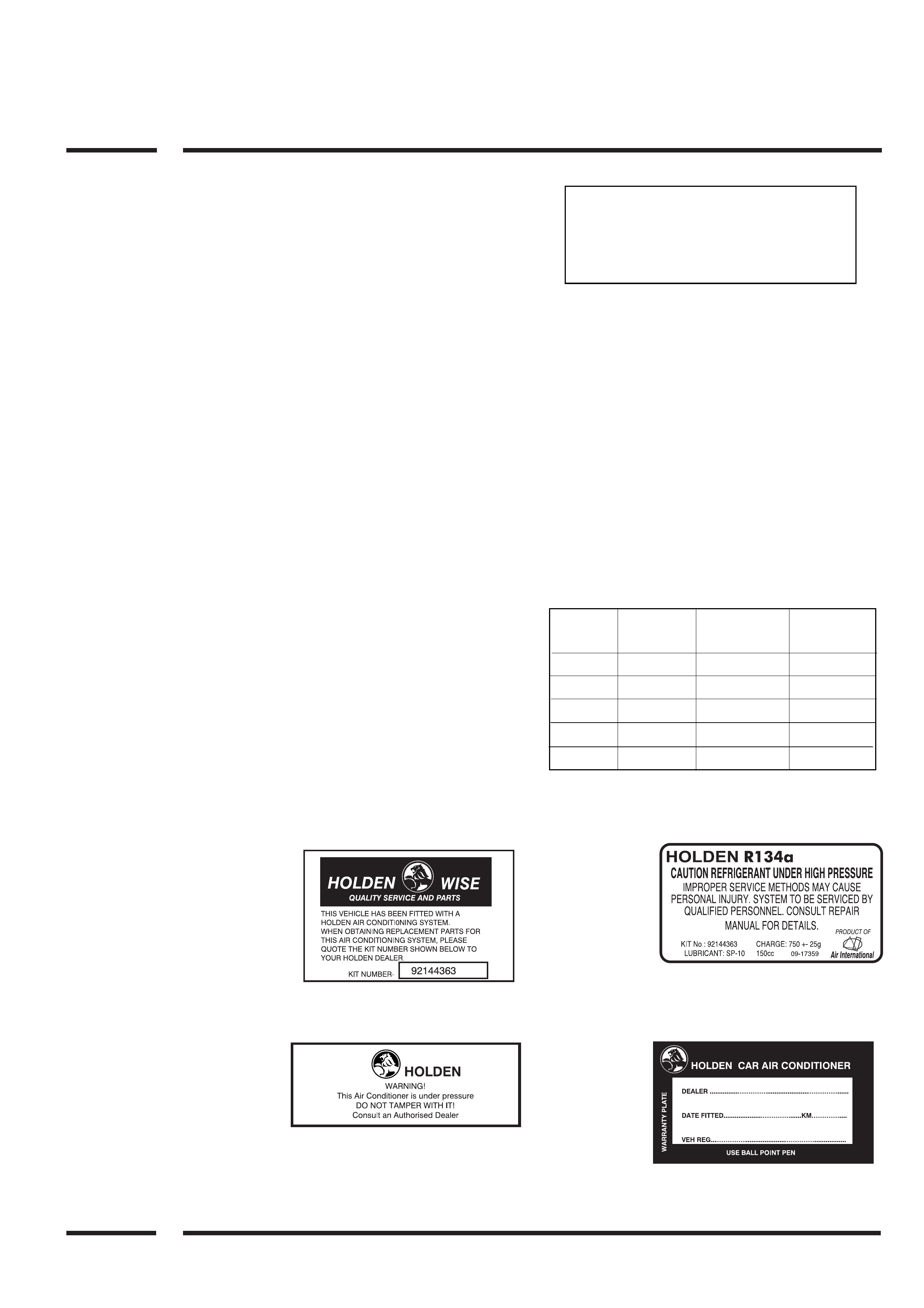
Labels
A/C Kit Part
Number:
Location —
Glove box
interior (The kit
number on this
label is to be
used for
reference when ordering A/C spare parts.
Warning
Label:
Location —
Radiator
support
Panel.
Warranty
Plate:
Location —
1 x Owners
Manual
1 x Firewall
(Use ball
point
pen-mark label with relative information).
Refrigerant
Label:
Location —
Radiator
support panel
- top LH side.

Specifications
Compressor — Delphi SP 10 (10 piston)
Clutch — 12 Volt, 6 Poly Vee
A/C Belt Size — 2300mm.
Condenser — Dual Pass Serpentine.
Evaporator — Laminated plate and fin design.
TX Valve — 1.5 ton externally equalised with charcoal dampening.
Pressure Switch — High Pressure Compressor Off 2940 ± 196kpaG.
Low Pressure Compressor Off 205 ± 19.6kpaG.
Refrigerant Capacity — R134a 750 ± 25 grams.
Filter Drier Receiver (FDR) — XH9 Desiccant - No sight glass.
Lubricating Oil — Sanden SP 10
‘O’ Ring Material — HNBR Colour - Green.
Compressor Oil Charge
(when first installed new) — 150cc (total system capacity).
Tightening Torques
Condenser Pad Fitting Bolts — 7 - 10NM
Filter Drier Pipe Connections — 13 - 15NM
Liquid Tube to Evaporator Pipe Connection — 13 - 15NM
Suction Tube to Evaporator Pipe Connection — 24 - 30NM
Suction Hose to Compressor Pad Fitting Bolt — 20 - 30NM
Discharge Hose to Compressor Pad Fitting Bolt — 20 - 30NM
Compressor Mount Bracket to Engine Bolts — 40 - 50NM
Compressor Mounting Bolts — 40 - 50NM
Wheel Nuts (Aluminium Wheels) — 125NM
Wheel Nuts (Steel Wheels) — 125NM
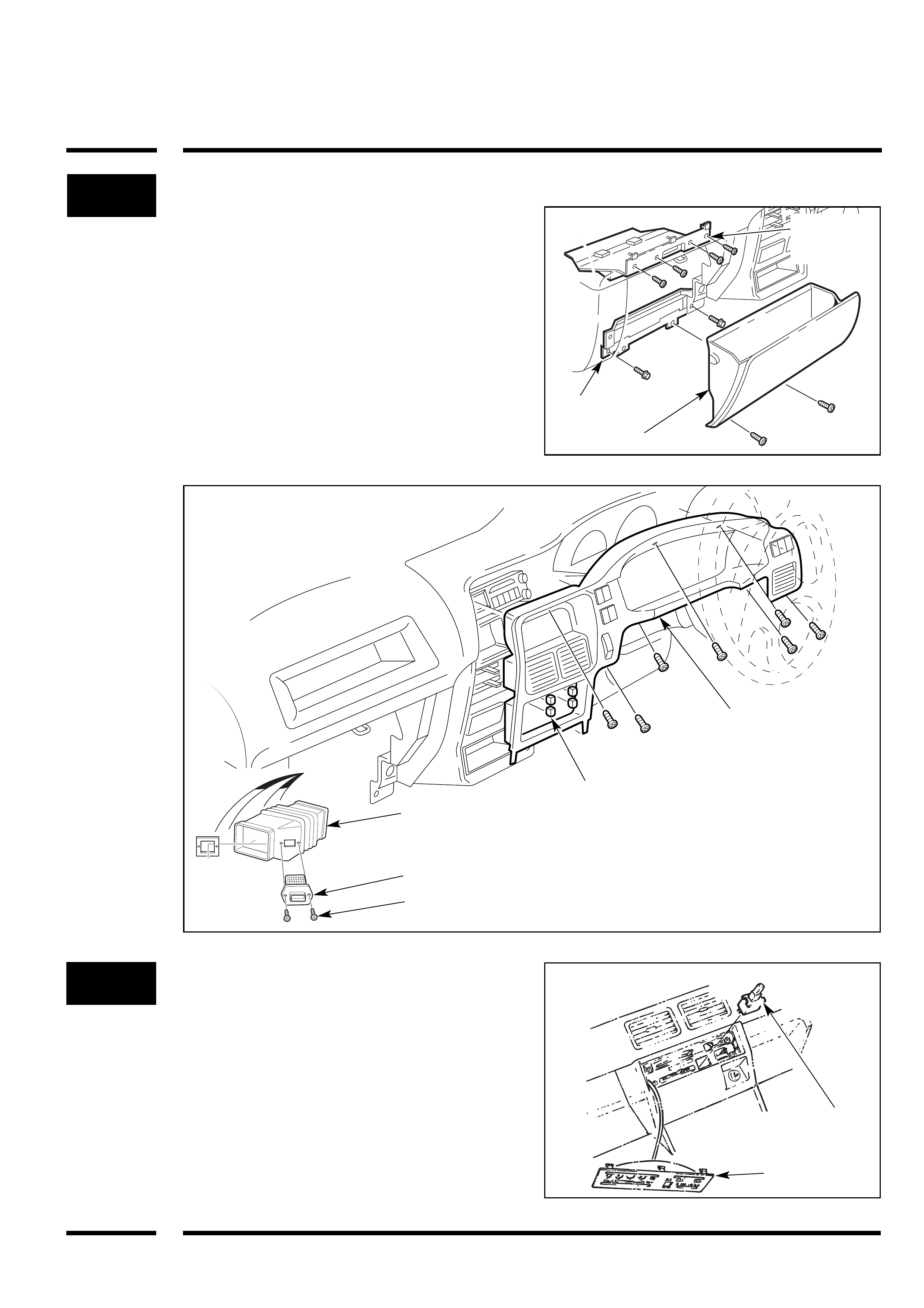
1Parts to be Removed (Interior)
a. Glove box (2 screws).
b. Glove box support (2 bolts).
c. Upper glove box panel (4 screws).
d. Air transfer duct (unclip).
e. Resistor (discard transfer duct, metal
resistor backing plate and 2 screws).
f. Remove plastic wire retainer from R/H
lower 6mm stud.
g. Upper dash surround (7 screws, 2
plugs).
Heater Bezel
Knobs
Resistor
Discard
Air
Transfer
Duct
Glove Box
2Air Conditioner Switch Installation
a. Unclip heater control bezel and knobs
and push out and discard the A/C
blanking plug from the heater control
bezel.
b. Clip air conditioner switch into vacant
position in dash.
c. Reinstall heater control bezel and
knobs (4).
A/C
Switch
Heater
Control Bezel
Upper Glove
Box Panel
Glove Box
Support
Upper Dash Surround
;;;
;;;
;;;
;;;
;;;
;;
;;
;;
3
4
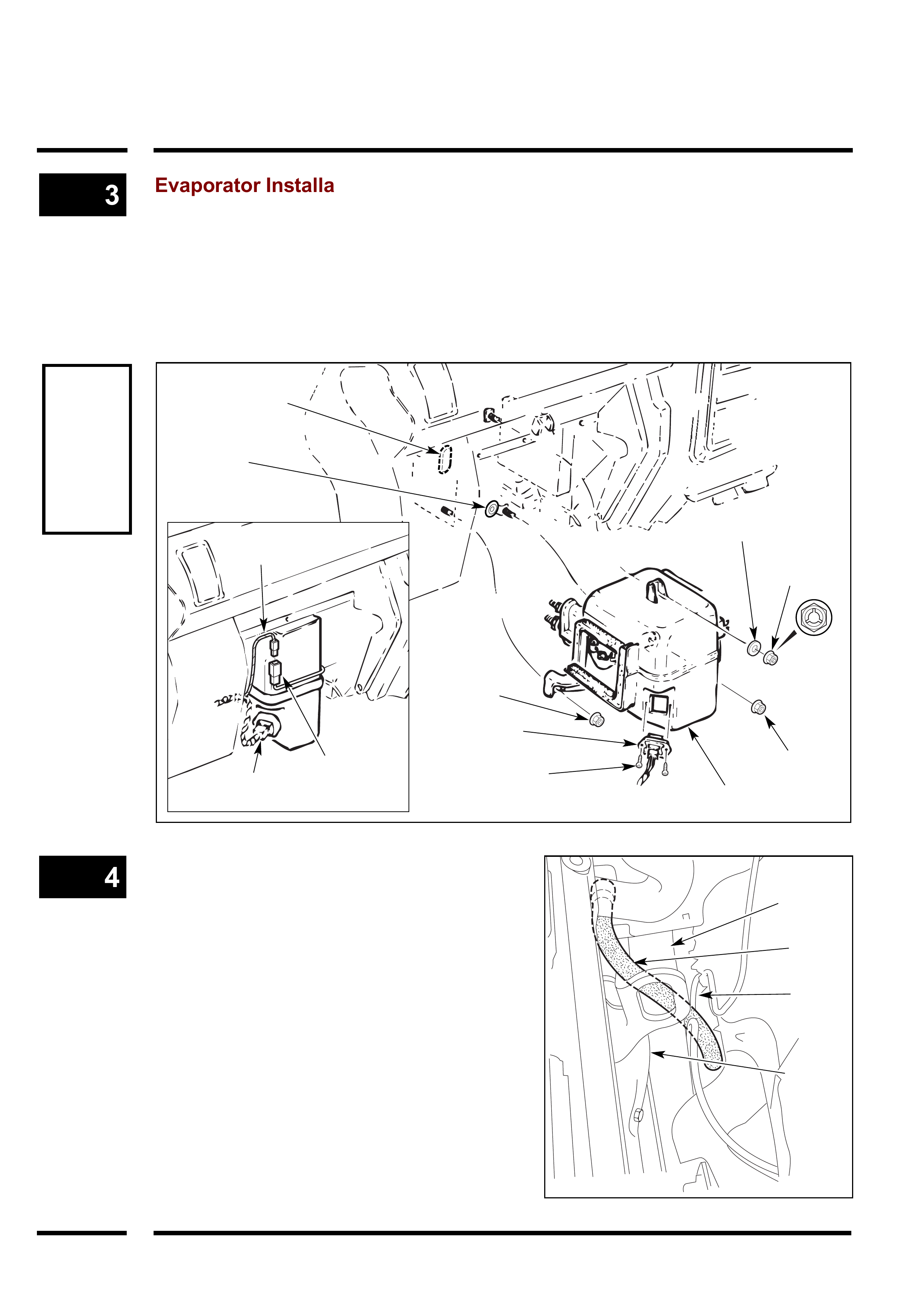
Evaporator Installation
a. Remove and discard (2) firewall rubber
blanking plugs.
b. Fit the original blower resistor to evaporator
case with (2) new self tapping screws.
c. Remove right lower blower case 6mm
nut and retain.
Evaporator Drain Hose Installation
a. From the engine bay install the drain hose
to the evaporator drain tube. Route drain
hose away from the exhaust manifold and
behind the brake tube as shown.
b. Re-install all parts.
CAUTION
Do not
overtighten
evaporator
mounting
nuts as stud
damage will
occur.
d. Install evaporator assembly into position
and retain with (1) supplied 6mm nut, (1)
original 6mm nut and (1) 6mm PAINT
STRIPPING nut and 7mm flat washer for
the upper mounting.
e. Connect evaporator wiring electrical plug
to original harness in vehicle, then
reconnect blower resistor electrical plug.
(2) Self
Tapping
Screws
Blower
Resistor
(1) 6mm Nut
(1)
Original
6mm Nut
Evaporator
(1) 7 x 25mm
Flat Washer
(1) 6mm Paint
Stripping Nut
Original
Harness
Evaporator Pipe
Blanking Grommet
Evaporator Drain
Hose Plug
Evaporator
Wiring Plug
Blower
Resistor Plug
Brake
Tube
Drain
Hose
Chassis
Rail
Exhaust
Manifold
g. Remove and discard the front bracket
and bolt used to secure the wiring
harnesses to the L/H side of the engine
block (as shown). Retain rear bracket
and retaining bolt.
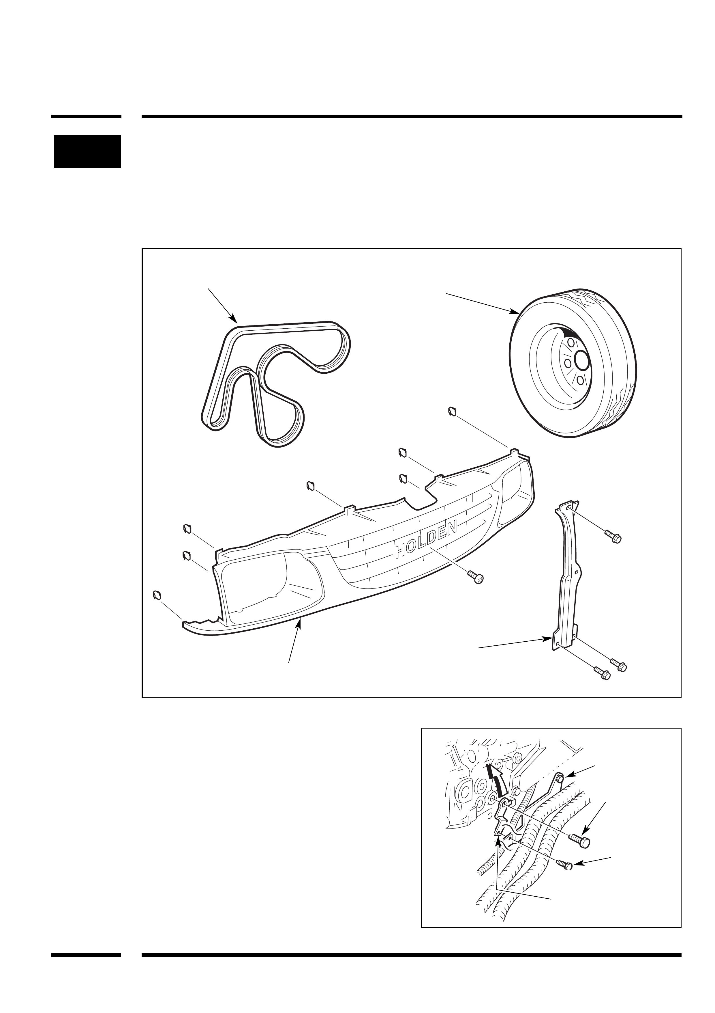
5Parts to be Removed
(Engine Compartment)
a. Grille (8) clips and (1) screw
b. Bonnet lock support (3) bolts.
c. Drive belt (discard).
d. Place vehicle on hoist or jack up front
and place on stands.
e. Left hand front wheel.
f. Detach LH side wheel arch rubber splash
panel.
Drive Belt
(Discard) Left Hand
Front Wheel
Grille
Bonnet
Lock
Support
Discard
M6 Bolt
Retain
Wiring Harness
Front Bracket
(Discard)
Wiring Harness
Rear Bracket
(Retain)
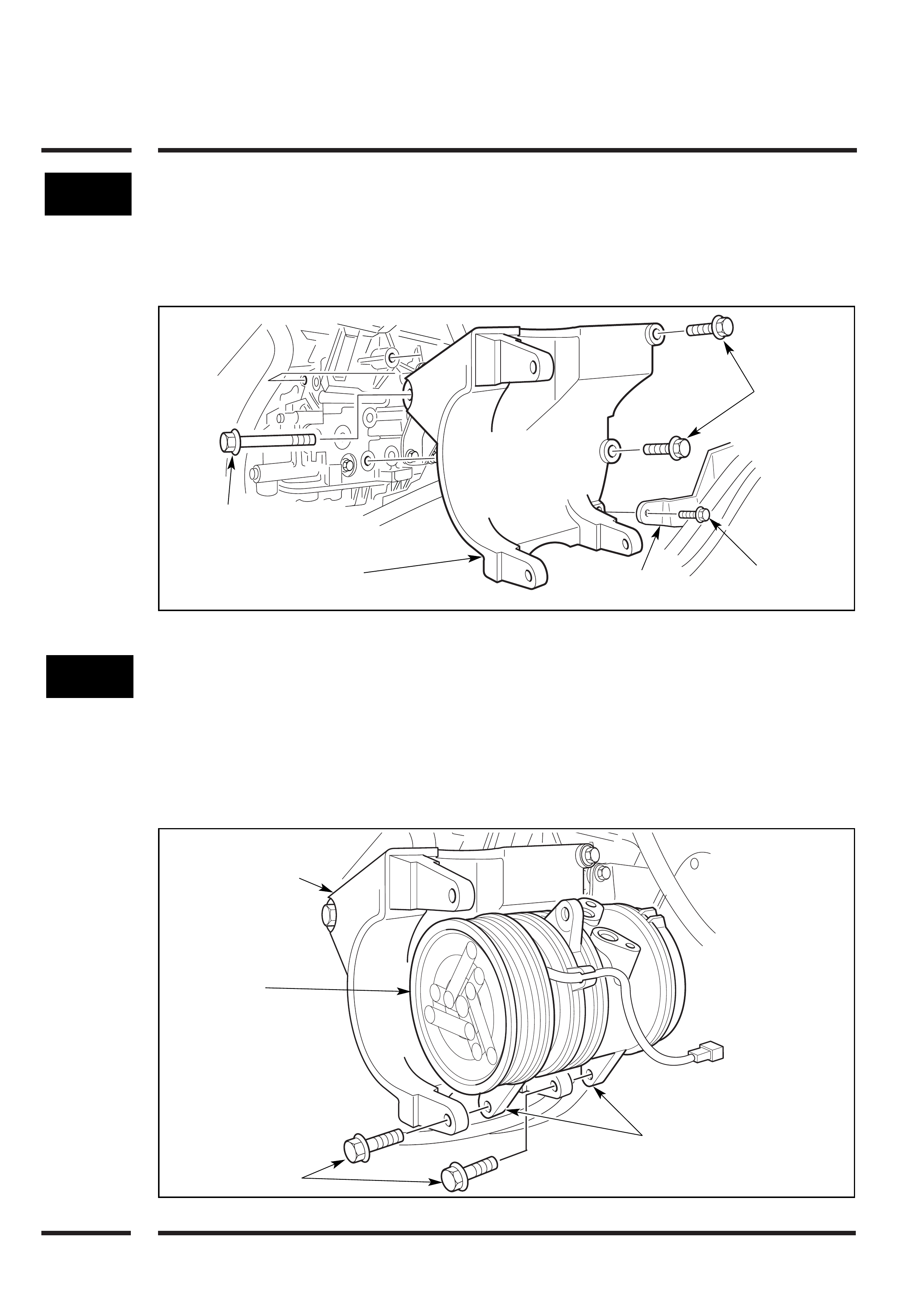
6Compressor Mount Installation
b. Secure the compressor mounting
bracket through the left hand side wheel
arch opening to the engine block using
(2) M10 x 30 washer faced bolts and (1)
M10 x 80 washer faced bolt.
Torque to 40-50Nm.
b. Fit wiring harness bracket to
compressor mounting bracket using
original bolt.
7Note: DO NOT secure the upper
compressor mounting bolt at this stage.
Later in the fitting procedure you will be
required to fit the suction and discharge
hoses then swing the compressor into
position and secure upper mount.
Compressor Installation - Part One
a. Assemble the compressor to the
compressor mounting bracket through
the left hand front wheel arch.
b. Fit the (2) M8 x 30 washer faced bolts to
the lower mounting lugs Leave loose at
this stage.
(1) M10 x 80
Washer Faced Bolt
Compressor
Mounting Bracket
Compressor
Mounting Bracket
Compressor
(2) M8 x 30
Washer Faced Bolts
Lower
Mounting Lugs
DO NOT
SECURE UPPER
MOUNTING
BOLT AT THIS
STAGE
Wiring Harness
Bracket
Original
Bolt
(2) M10 x 30
Washer
Faced Bolts
8
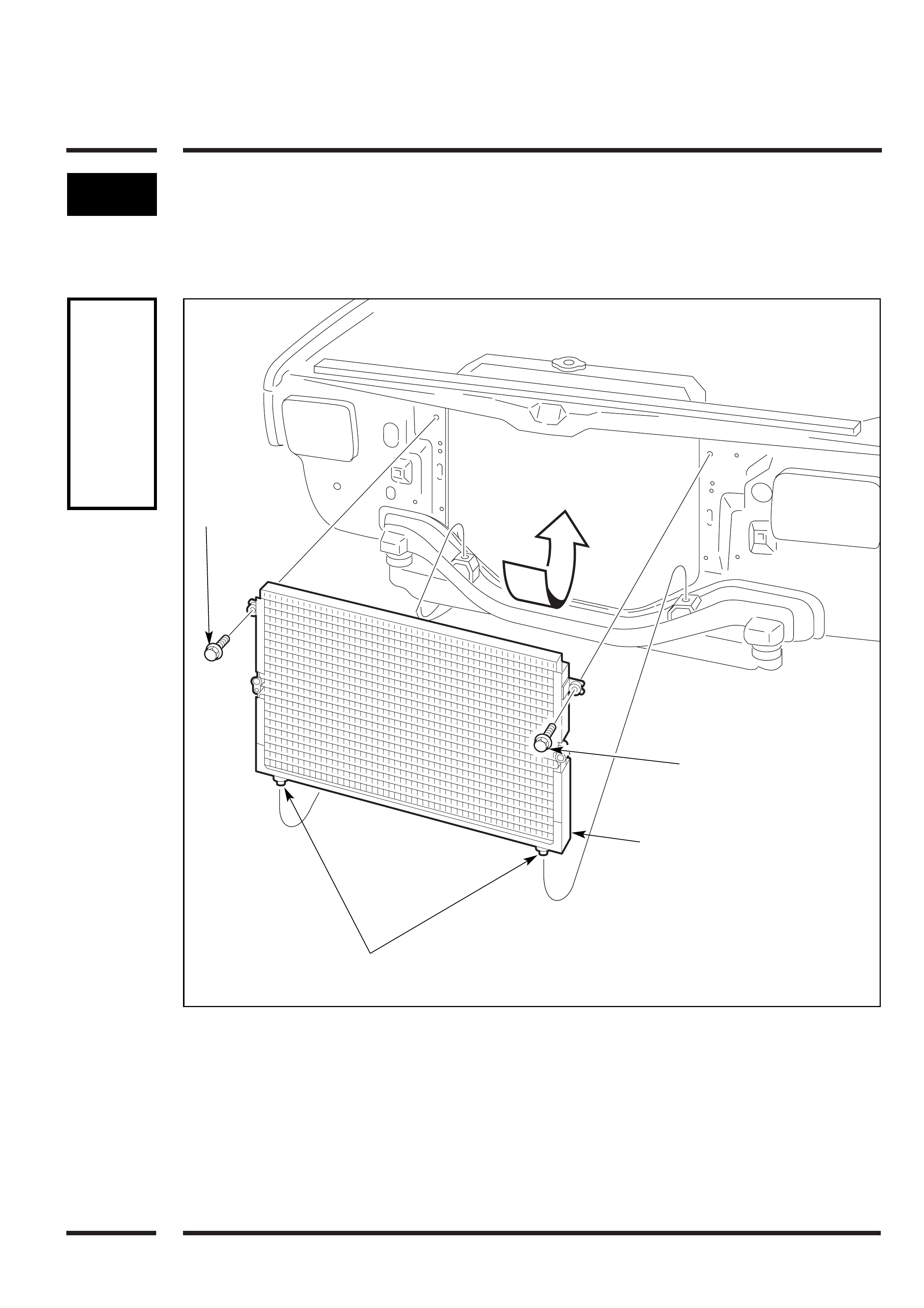
CAUTION
Be careful
not to
cause
radiator
face
damage
when
installing
condenser
Condenser Fitment
a. Insert condenser into position ensuring
mounting cushions are in position and
secure with (2) 6 x 30mm bolts in the
position shown.
6 x 30mm Bolt
Condenser
Mounting Cushions
6 x 30mm
Bolt
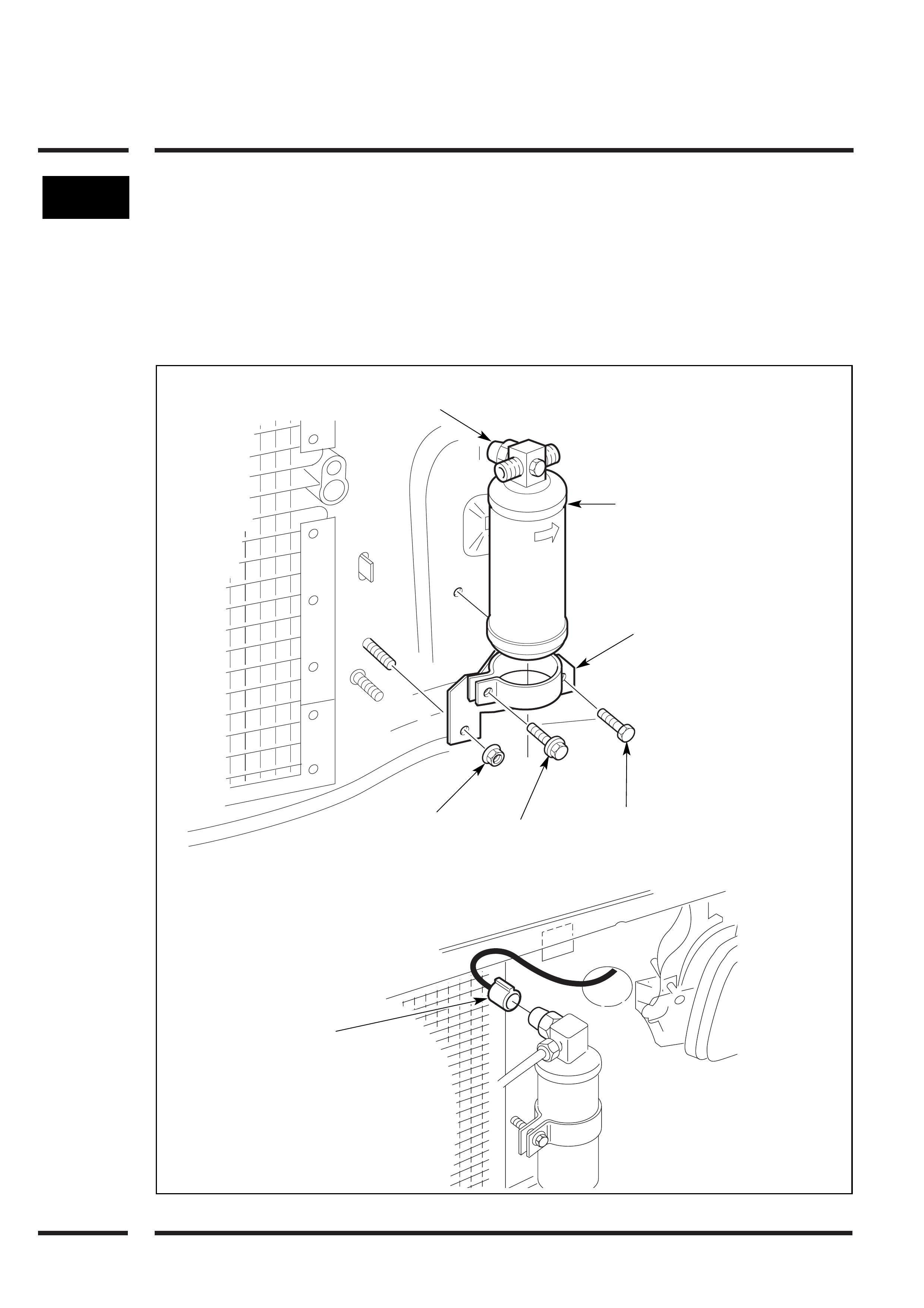
9FDR Bracket, FDR and Pressure
Switch Wiring Installation
a. Fit FDR bracket to radiator support panel
using (1) M6 x 12mm washer faced bolt
and (1) existing 8mm washer faced nut.
b. Insert filter drier into bracket, position as
indicated below and fit (1) M6 x 30mm
washer faced clamping bolt.
NOTE: Do not tighten FDR clamping bolt
at this stage.
c. Connect pressure switch to loom plug.
NOTE: Ensure that the filter drier is fitted
with the pressure switch facing back
towards the engine.
FDR
FDR
Bracket
Existing Nut M6 x 30
Washer
Faced Bolt
M6 x 12
Washer
Faced Bolt
Pressure Switch Plug
(Facing Back Towards Engine)
Pressure Switch
Connection
IN
OUT
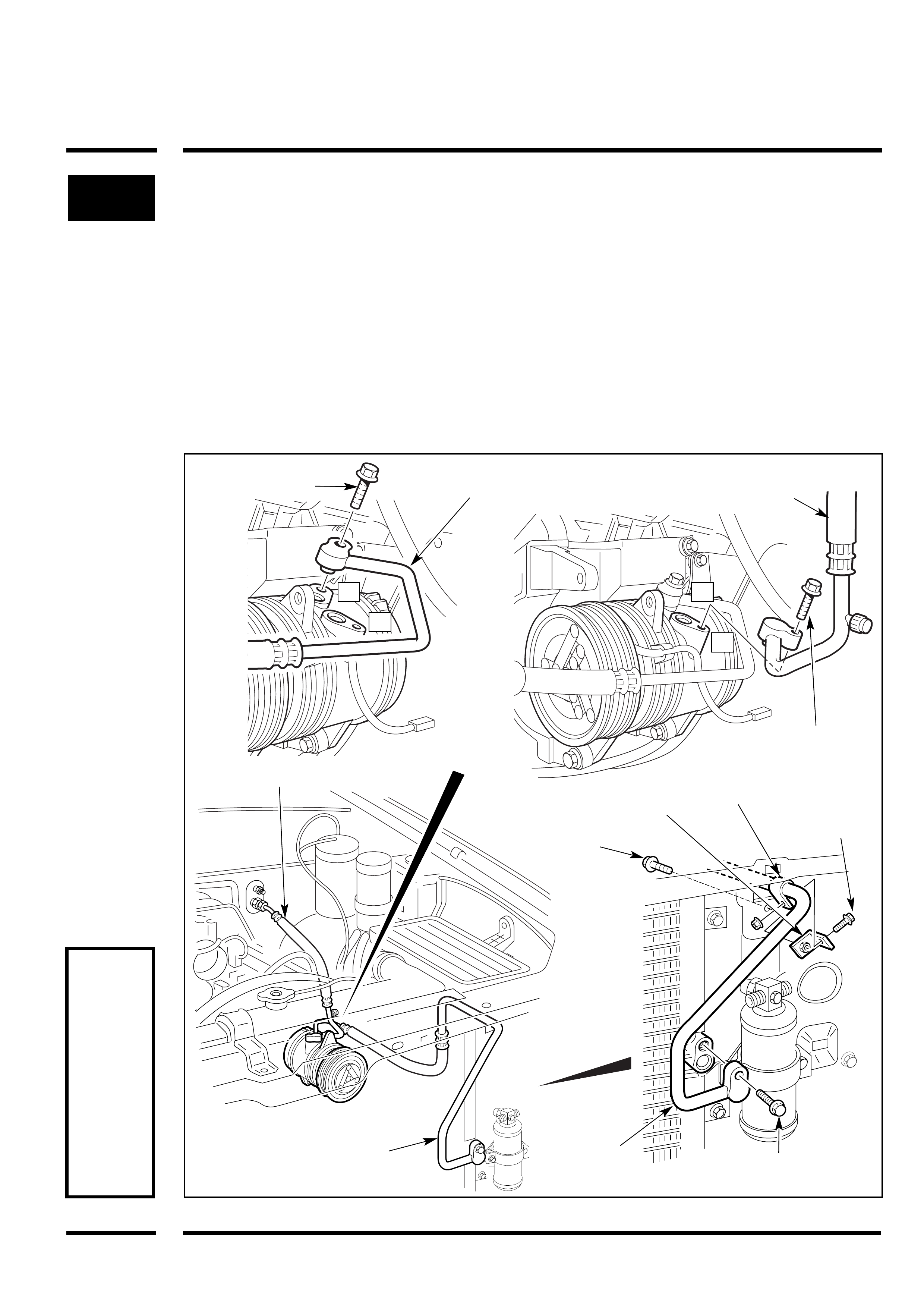
10 Discharge & Suction Hose
Installation - 4 x 2 & 4 x 4 Vehicles
a. Pass the discharge tube through the
radiator support panel.
b. Connect the discharge hose to the
condenser using (1) M6 x 60mm washer
faced bolt.
c. Secure the discharge tube to the
radiator support panel using (1)
mounting bracket, (1) clamp, (2) M6 x 12
bolts and (1) M6 nut.
NOTE
Tube
tightening
torques are
indicated
on Page 1
All 'O' rings
are pre
lubricated
at the
manufacturer
d. Connect the suction hose to the
evaporator outlet tube and route to
compressor.
e. Remove the compressor discharge (D)
port cover (discard cover and bolt).
Install the discharge hose pad fitting to
the compressor and secure with (1) M8 x
30 washer faced bolt.
f. Remove the compressor suction port (S)
cover (discard cover and bolt). Install the
suction hose pad fitting to the
compressor and secure with (1) M8 x 30
washer faced bolt.
Suction Hose
(to Evaporator Outlet)
Suction Hose
Discharge
Hose
Discharge
Hose
M6 x 12
Bolt
‘P’ Clamp
M6 x 60
Washer Faced Bolt
Discharge Tube
Mounting Bracket M6 x 12
Bolt &
M6 Nut
Discharge Hose
(to Condenser)
(1) M8 x 30
Washer Faced
Bolt
(1) M8 x 30
Washer Faced Bolt
S
D D
S
11
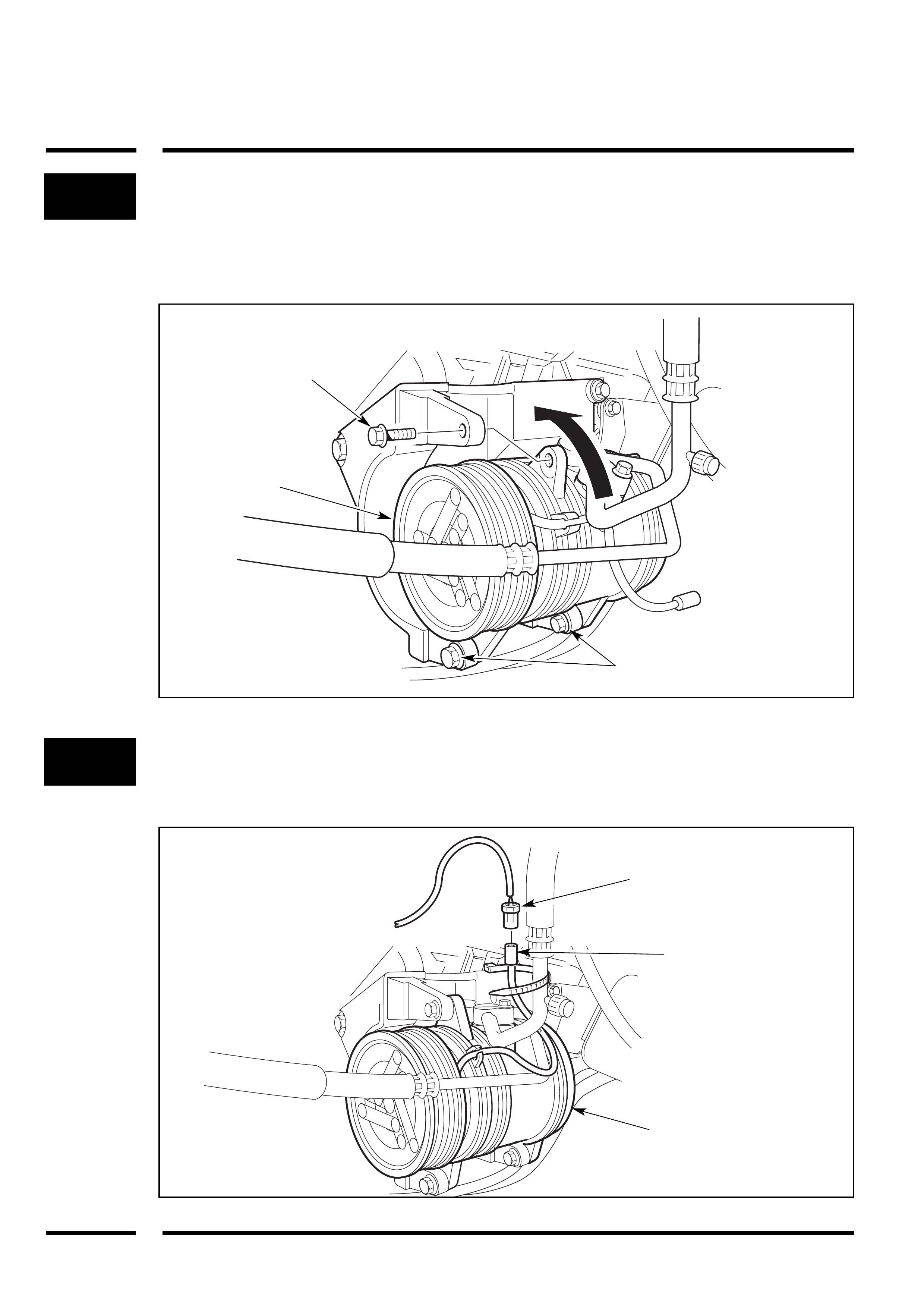
12 Compressor Clutch Connector
a. Connect compressor clutch wire to the
vehicle harness. The vehicle harness
connector is taped back on vehicle
wiring harness.
Cable tie to avoid fouling.
Compressor Installation - Part Two
4 x 2 & 4 x 4 Vehicles
a. Swing compressor towards top
compressor mounting bracket lug and
secure as shown using (1) M8 x 30
washer faced bolt. Torque to 20 - 30Nm.
b. Tighten lower compressor mounting
bolts (previously loosely fitted).
Torque to 20 - 30Nm.
Vehicle Harness
Connector
(1) M8 x 30
Washer Faced Bolt
Compressor
Lower Compressor
Mounting Bolts
Compressor
Vehicle Harness
Connector
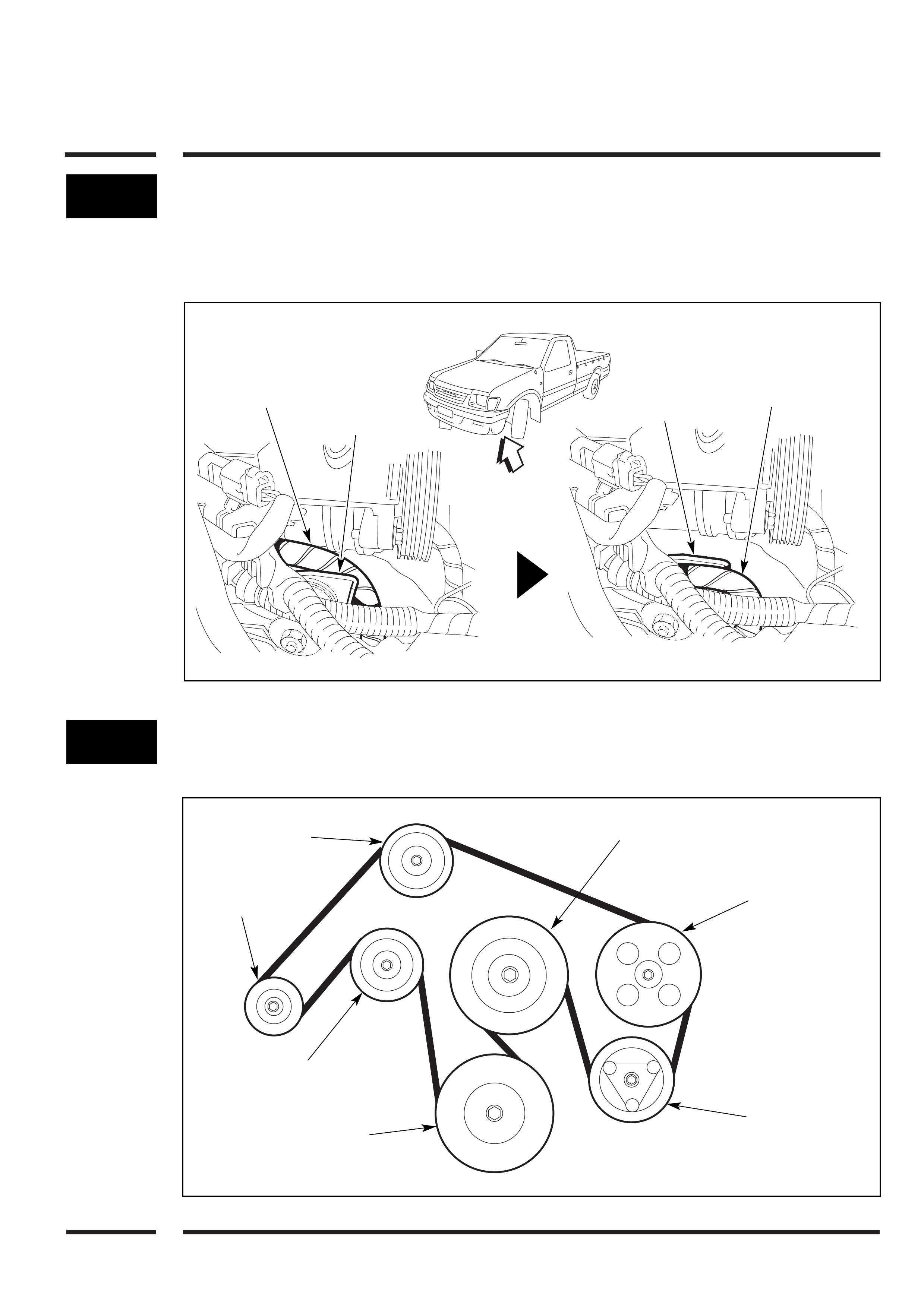
14 Compressor Drive Belt Installation
a. Fit new drive belt and route as shown.
13 Breather Tube Harness
Re-location - 4 x 4 Vehicles Only
a. Re-locate the breather tube harness, by
hand, to under the chassis mounting as
shown.
Idler Pulley
Alternator
Pulley
Tensioner
Pulley
Crankshaft
Pulley
Compressor
Pulley
Power Steering
Pulley
Water Pump
Pulley
Breather Tube
Harness
(Over Bracket) Chassis
Mounting
Bracket
Viewed from
Underneath
Vehicle
Breather Tube
Harness
(Under Bracket)
Chassis
Mounting
Bracket
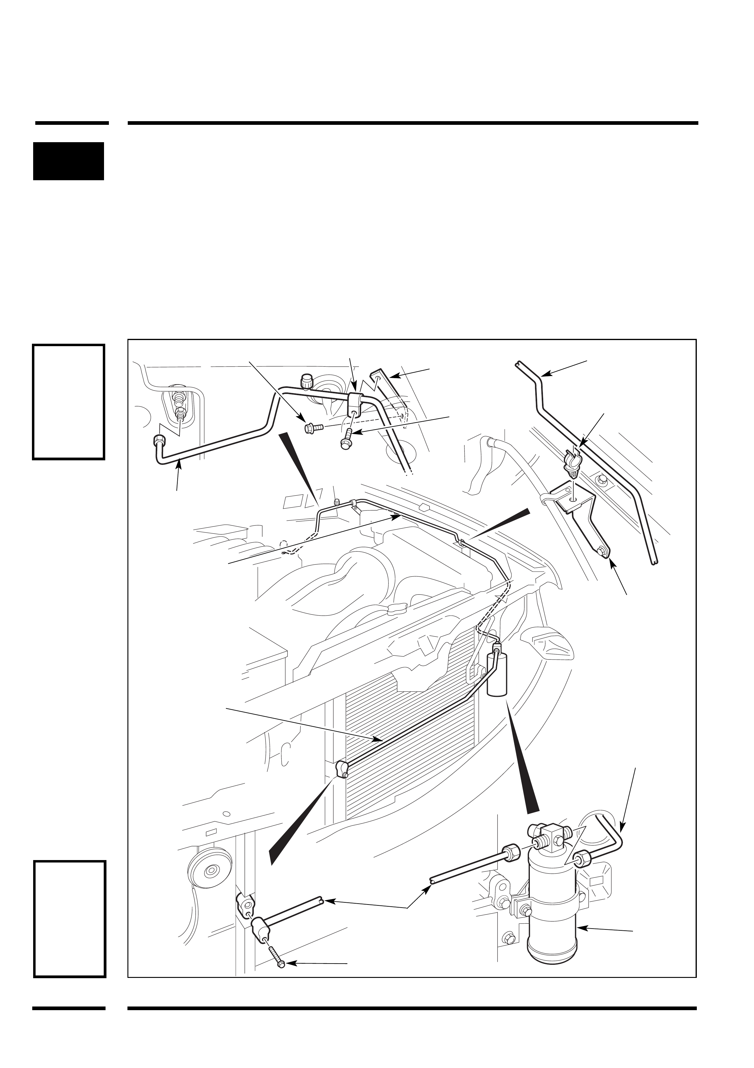
15 Liquid Tube Installation
a. Install liquid tube (A) between the FDR
inlet fitting and the condenser pad
fitting. Secure to the condenser using (1)
M6 x 60 washer faced bolt.
Note: Ensure liquid tube ‘A’ is parallel to
the condenser tubes as this tube is seen
through the grille.
b. Install liquid tube (B) from the engine
bay through the radiator support panel
and connect to the FDR outlet fitting and
the evaporator inlet tube.
c. Fit the plastic retaining clip into the
existing bracket on the LH side inner
guard to secure liquid tube (B).
d. Fit the liquid tube support bracket behind
the washer bottle lug using existing bolt.
Secure liquid tube (B) to the mounting
bracket using (1) clamp and (1) M6 x 12
bolt.
e. Tighten the FDR bracket retaining bolt.
NOTE
All 'O' rings
are pre
lubricated
at the
manufacturer
NOTE
Tube
tightening
torques as
indicated
on Page 1
Liquid Tube (A)
Liquid Tube (A)
(Ensure tube is
parallel with
condenser
tubes) Liquid Tube (B)
Liquid Tube (B)
Liquid Tube (B)
Liquid Tube (B)
Plastic Clip
Liquid Tube
Retaining
Bracket
(1) M6 x 12
Bolt
Existing Bolt Clamp
Existing
Bracket
FDR
(1) M6 x 60
Washer Faced Bolt
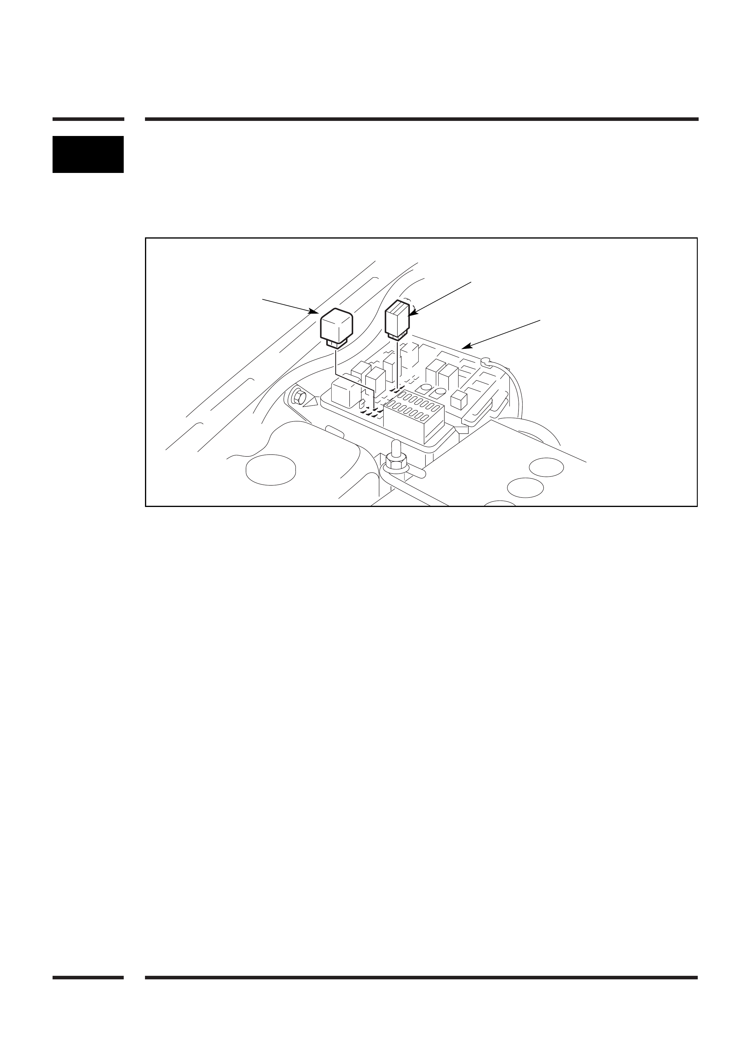
16 Relay Installation
a. Locate fuse and relay panel, RHS inner
guard, remove cover and fit (2) relays
(large and small) supplied to positions
shown.
Fuse/Relay
Panel
Relay (Small)
Relay (Large)
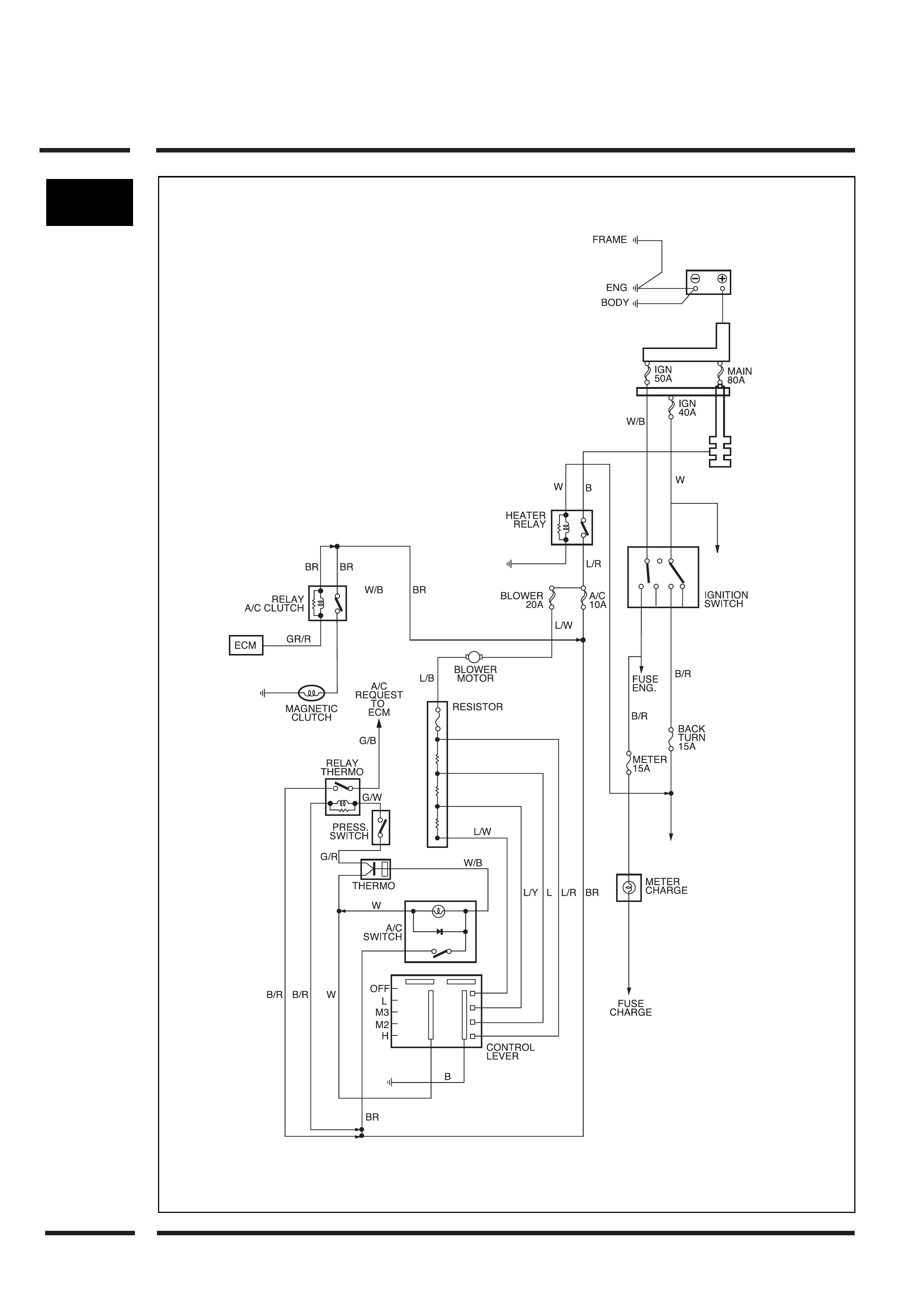
17
Wiring Diagram
18
CEFG
AB
D
H
LOW HIGH
REFRIGERANT
RECOVERY
UNIT VACUUM
PUMP
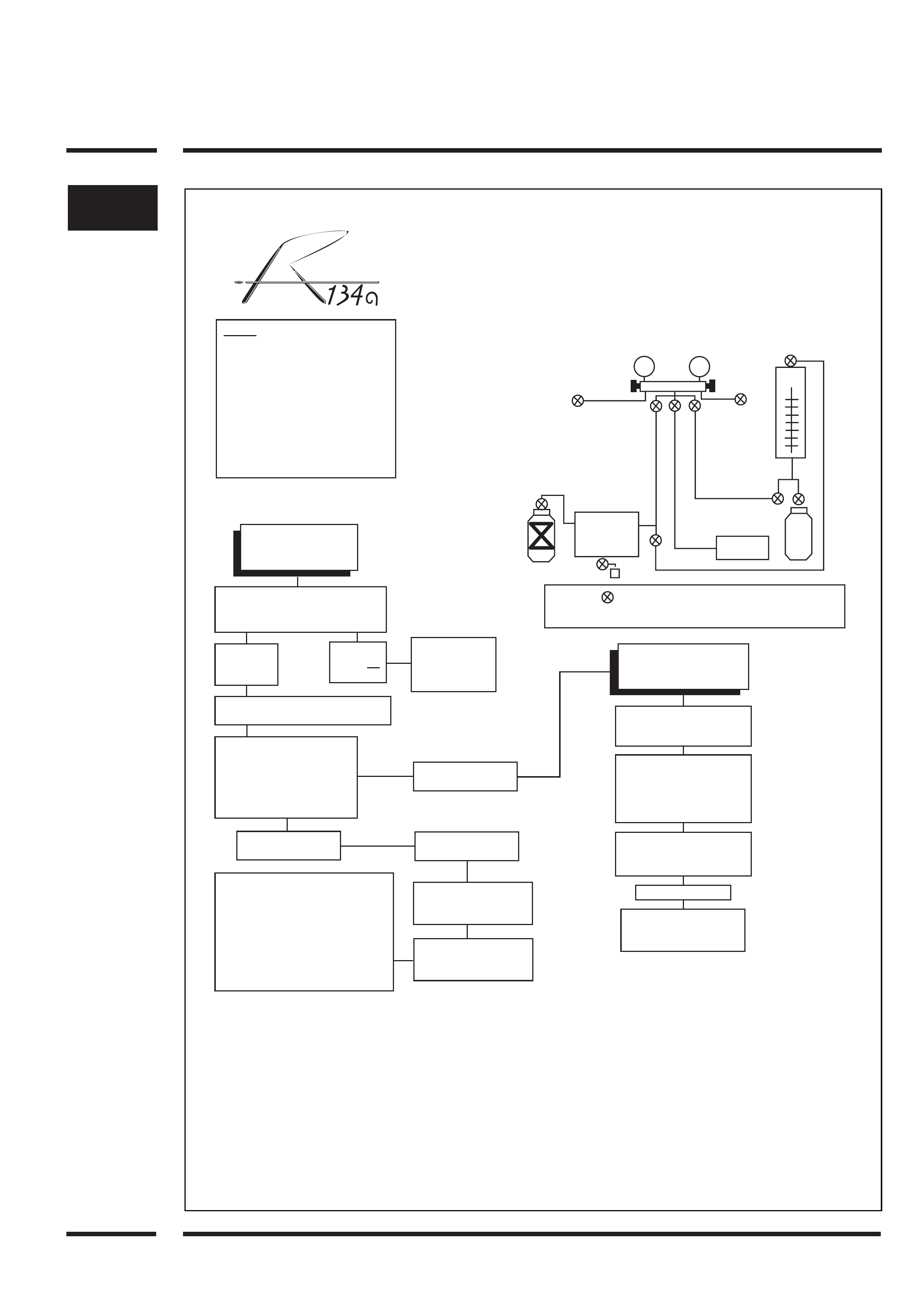
SPECIFIED CHARGE 750 +/- 25 GRAMS
NOTE: 1. Gloves and safety glasses
must be warn.
2. Work in a well ventilated
area.
3. Do not smoke near
refrigerant.
4. Aviod PAG oil contacting
paint work. Wash off
immediatly.
5. Do not smoke near
refrigerant.
Start vacuum pump, open valve F,
open valves A & C low pressure
filling hose.
High side
gauge reads
below zero
High side
gauge not
below zero
Blockage or leak
evident in system.
find cause and
rectify.
Leave valves A, C, & F open. Slowly
open high side valves B & D.
Evacuate system to 6 kpa
absolute.
Close valves A, B & F.
System must maintain 6 kpa
-absolute for a minimum
of 15 mins.
Low pressure gauge
needle steady
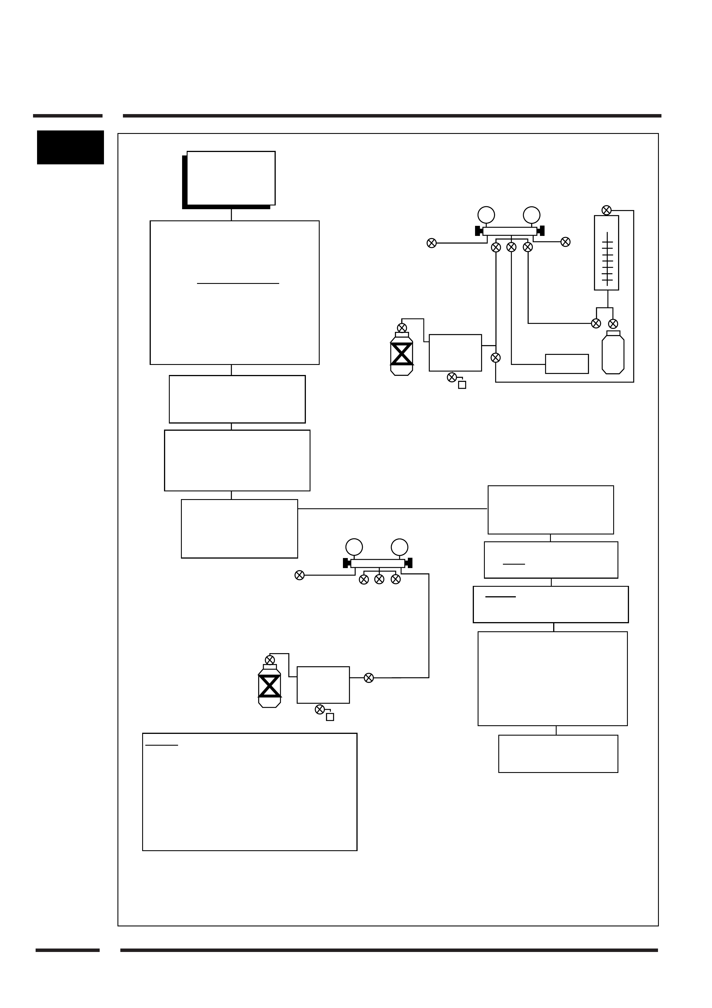
Recover refrigerant from
system, open valves A, B, C,
D, E and H. After the recovery
procedure close valve E. Open
valve F and continue the evacuation
procedure for a minimum of 15 mins
then close valves A, B & F. Turn
pump off. (Refer Fig. 1)
Low pressure gauge
needle rises.
Continue evacuation
for 15 mins.
Partially charge system
with 200 grams of
refrigerant
Partially charge system with
200 grams of refrigerant
through high filling hose.
Locate leakage using an
electrical leak detector.
Check on the underside of
all fittings and components
Recover refrigerant from
system open valves A, B, C,
D, E, & H. (Refer Fig. 1)
Repair leak source
Continue with evacuation
and charging procedure
as per steps 1-3
NOTE: Indicates stop tap or valve-fit these
whenever a hose has to be removed
Fig. 1
Check for leakage using
an electronic leak
detector
STEP 1
EVACUATION
STEP 2
LEAK TESTING
19
C
EFG
A
B
D
H
LOW
HIGH
REFRIGERANT
RECOVERY
UNIT
VACUUM
PUMP
C
A
B
D
H
LOW
HIGH
REFRIGERANT
RECOVERY
UNIT
First Aid: In the event of R134a contacting the
eye, carry out the folllowing procedure:-
1. Do not rub eye
2. Splash large quantities of water into the eye to
raise the temperature.
3. Continue to irrigate the eye for 15-20 mins.
4. Take patient without delay to hospital or
physician.
5. Do not attempt to treat yourself.
Start engine set to fast idle.
Activate A/C switch. Set
controls to maximum cooling
and high fan speed.
Open low side valves, A & C
slowly and complete the
charging process (If required).
Caution: do not allow more than
275 kpa to register on the low
side gauge during charging.
Close all valves and taps.
Remove high and low filling hoses,
make sure valves C & D are closed.
Connect high side filling hose to
recovery unit inlet side. Open valves
A, B & D. Switch on recovery machine
and remove all refrigerant in filling
hoses. (Refer Fig. 3)
Carry out performance testing.
Refer appropriate workshop
manual for specifications.
Fig. 3
Fig. 2
Warning: Never run compressor
without refrigerant in
system as the compressor
relies on refrigerant/oil flow.
Any oil displaced during the
refrigerant recovery process
must be replaced in the
system before charging can
commence. The R134a
system uses P.A.G. (poly-
alkaline glycol) lubricating
oil. Use specified oil type.
Warning: Never charge system
through the high side
with the compressor
running.
Open high side valves B, D & G.
Allow as much refrigerant as
possible to enter system, but
do not let more than the specified
amount enter the system.
Close valves B & D. rotate
compressor front plate 12
revolutions to ensure no
liquid is trapped in the
compressor.
STEP 3
CHARGING
SYSTEM