Page 1 of 7
IMPORTANT
NEVER DRIVE THE VEHICLE FORWARD OR REARWARD WITH THE TONNEAU OPEN OR UNLOCKED
PR E-DELIVERY CARE FOR PAI N TED TONNEAU COVER
IMPORTANT NOTE:
PLEASE UNDERSTAND YOUR TONNEAU IS A FRESHLY PAINTED SUR FACE AND ACCORDI NGLY
HAS BEEN CAREFULLY PACKED IN BUBBLE PLASTIC AND WRAP GUARD T O PROTECT THE PAINT
FINISH.
IT IS NECESSARY TO POLISH THE PAINT TO REMOVE THE EFFECT OF THIS WRAP GUARD.
PLEA SE DO NOT USE FILL ER TYPE POLISHES FOR THIS OPER ATI ON.
THE RECOMMENDED POLISH IS A NON-FILLING MACHINE GLAZE TYPE SUCH AS 3M “PERFECT IT
3” OR EQUIVALENT.
BEFORE FITTING, ENSURE THAT YOUR TONNEAU COVER FITTING KIT IS COMPLETE AND YOUR
KEYS MATCH THE LOCK S. PL EASE THORO U GHLY READ FITTI NG INST R UCTIO N S BEFO RE
ATTEMPTING TO FIT YOUR NEW TONNEAU COVER.
YOUR TONNEAU COVER IS COMPATIBL E WITH THE GENUINE HOL DEN CARGO LINER AND
SHOULD BE COMPATIBLE WITH MOST OTHER BRANDS OF CARGO LINER.
Division of HOLDEN Ltd ACN 006 893 232
FD1113
07AP04
COPYRIGHT
Reproduction in whole or part
prohibited without written approval
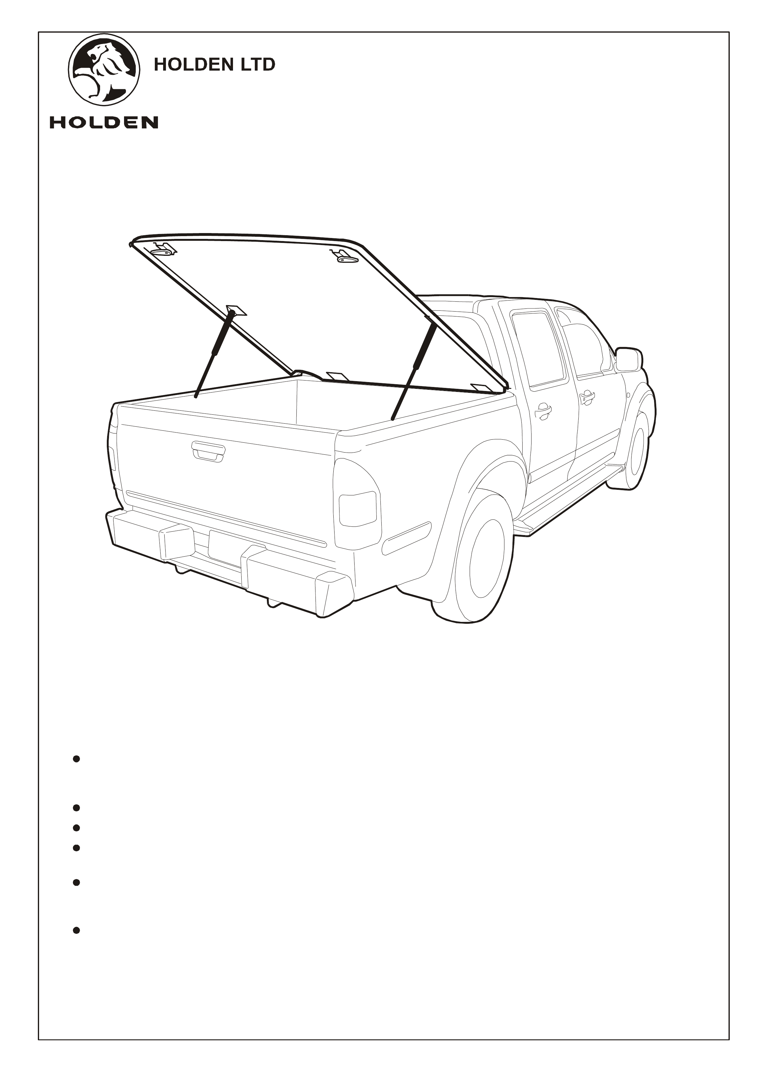
FITTING INSTRUCTIONS FOR
RA RODEO CREW CAB
TONNEAU COVER - HARD TOP
FITTING INSTRUCTIONS:
NOTE:
NOTE:
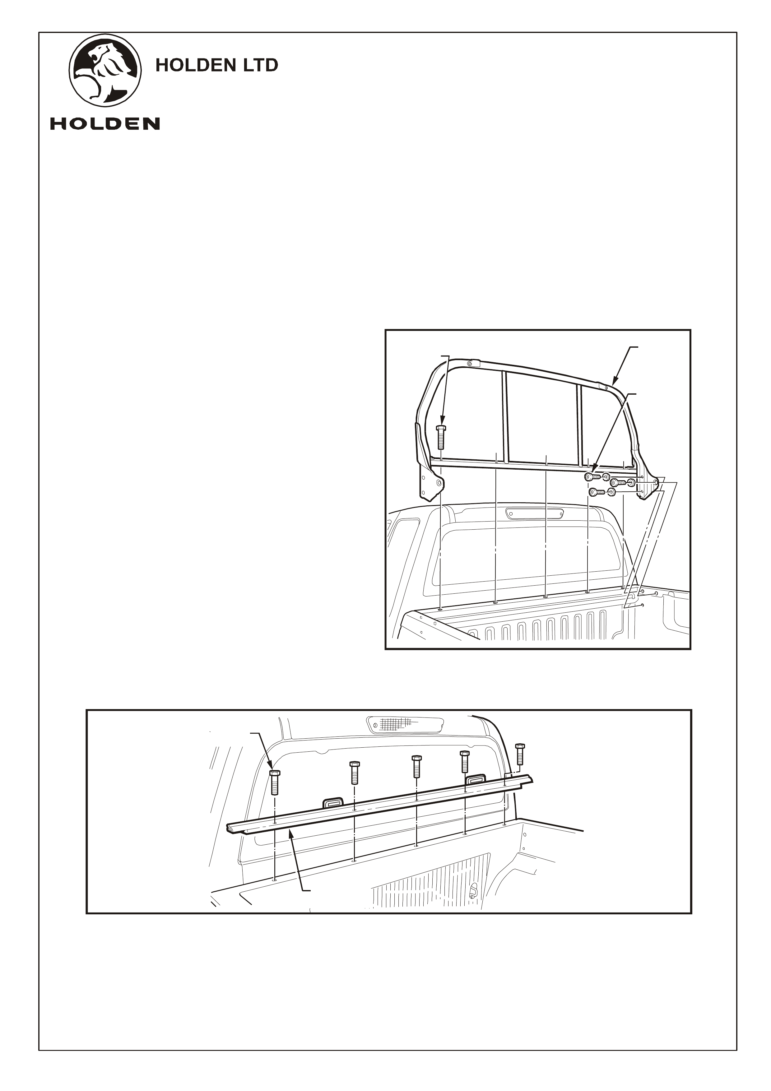
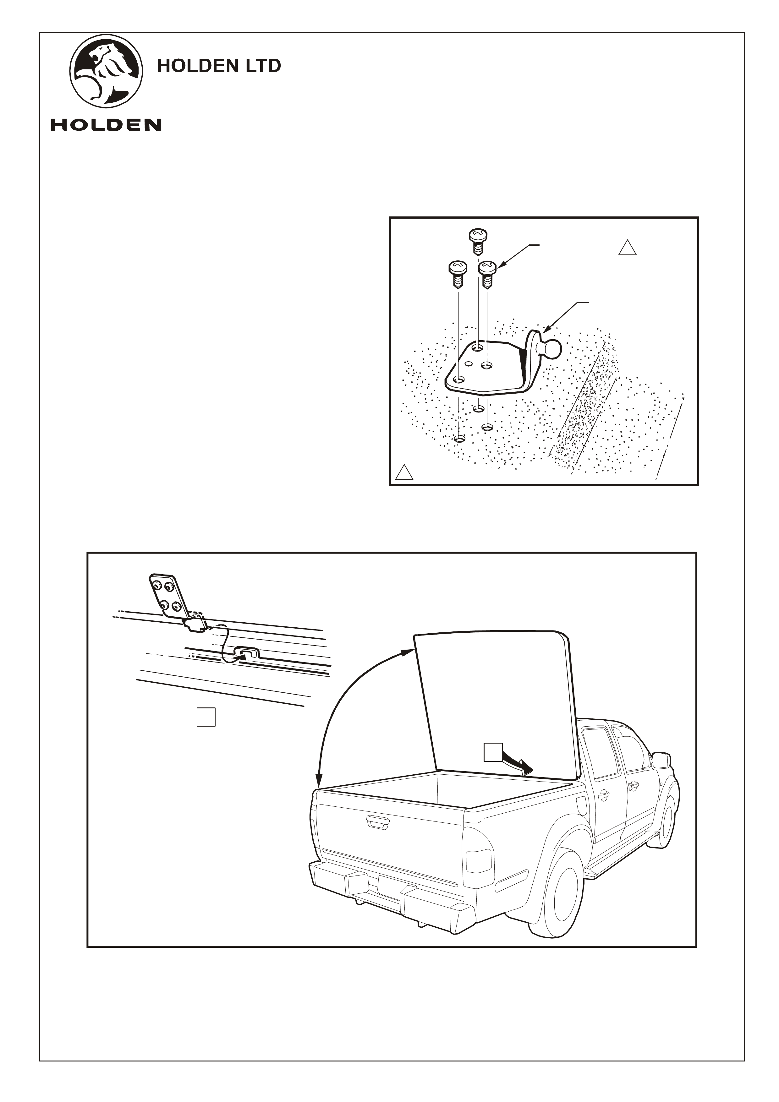
1. To fit the hard tonneau cover, first remove the
existing header bar. Remove the bolts
securing the header bar to the front tray rail
(5 places - located under the velcro strips if
tonneau is fitted) and the T40 Torx screws
securing the left and right-hand side
mounting brackets (6 places). Carefully lift
off the header bar (retain mounting bolts and
Torx screws for re-use and bar as refitting
may be required at a later date).
Refer to Figure 1.
If a cargo liner is fitted the front bar
assembly is fitted over the liner using the
extra long M6 X 20 screws supplied with the
fitting kit.
Before tightening the bolts or screws
adjust the front bar assembly so it sits as far
to the rear of the vehicle as possible.
2. Fit the front bar assembly using the 5
retained bolts. Refer to Figure 2.
TOOLS REQUIRED:
Electric Drill (Battery Powered), Phillips Head Bit No. 2, 10mm Socket, Extension, Rachet, Torx Bit T40,
Allen Key 5mm, Marking Pen, Corrosion Protection Paint Clean Rag.
and
FIGURE 1
BOLT
(5 PLACES)
EXISTING
HEADER
BAR
SCREW &
WASHER
(6 PLACES)
FIGURE 2
BOLT (
5 PLACES)
RETAINED OR
SUPPLIED SCREWS
-
FRONT BAR
ASSEMBLY
Page 2 of 7
Division of HOLDEN Ltd ACN 006 893 232
FD1113
07AP04
COPYRIGHT
Reproduction in whole or part
prohibited without written approval
FITTING INSTRUCTIONS FOR
RA RODEO CREW CAB
TONNEAU COVER - HARD TOP
FITTING INSTRUCTI ONS: -
continued
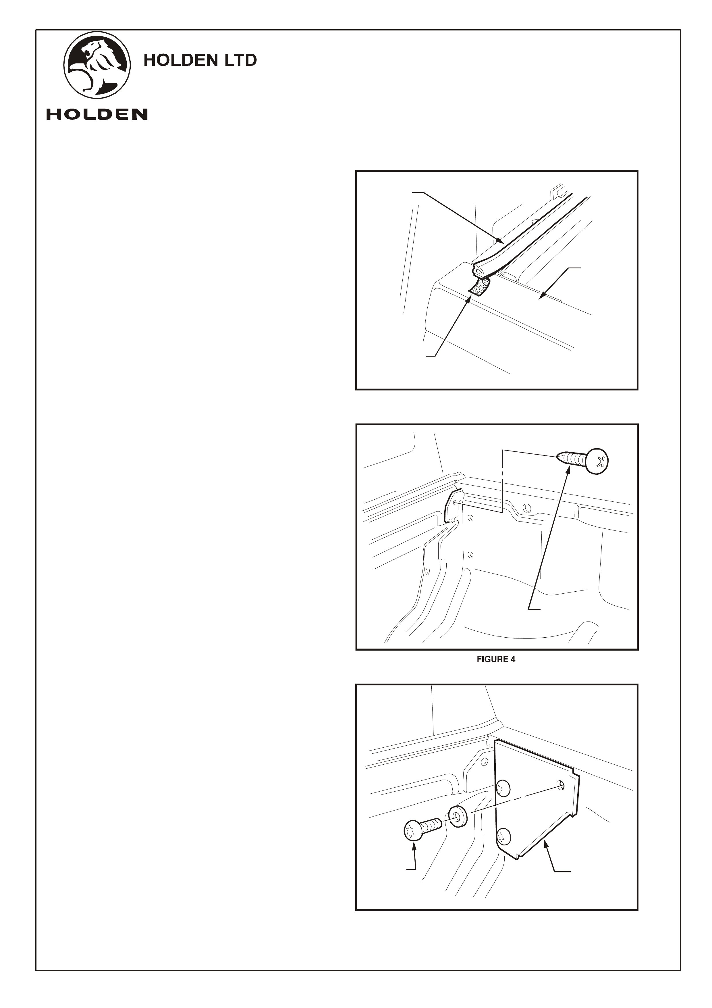
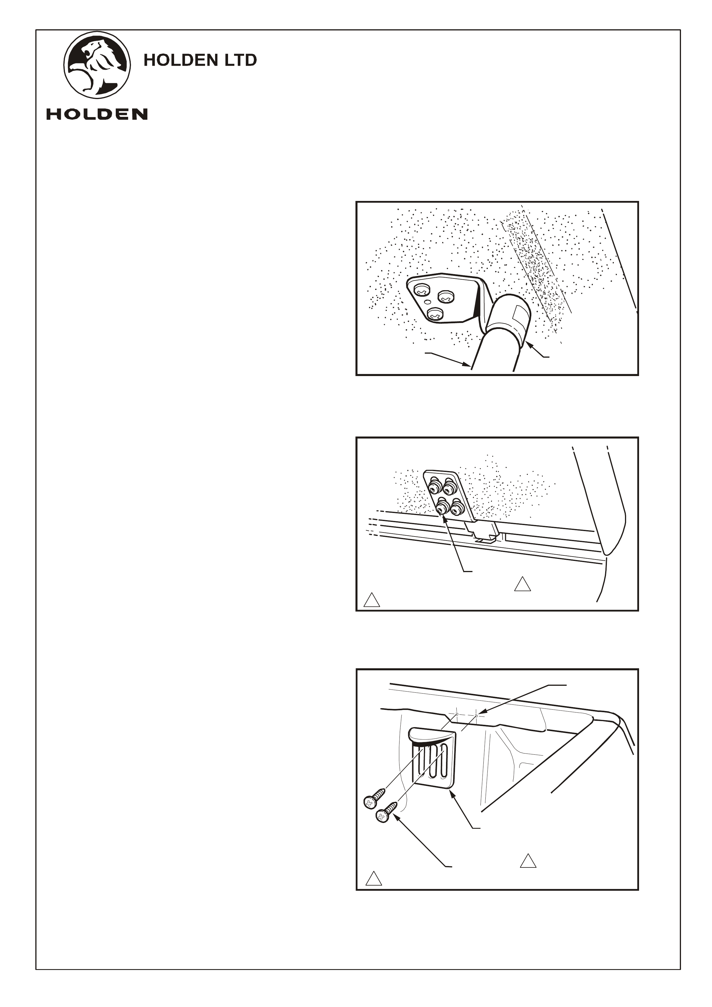
3. Peel the protective backing paper from the
double-sided tape at the end of each seal
and press the ends down on to the tray rail
surface. Refer to Figure 3.
4. Drill a 2mm dia. pilot hole through the right-
hand side tray corner bracket and end plate
where indicated and fit a self-drilling re-
enforcement screw. Repeat on the left-hand
side. Refer to Figure 4.
5. Using the retained T40 Torx screws, fit the
right-hand side support plate to the tray wall
as shown. Repeat on the left-hand side.
Refer to Figure 5.
SEAL
PROTECTIVE
BACKING
PAPER
SUPPORT
PLATE
RETAINED
T40 TORX
SCREW
FIGURE 3
FIGURE 5
REINFORCING
SCREW
TRAY
RAIL
Page 3 of 7
Division of HOLDEN Ltd ACN 006 893 232
FD1113
07AP04
COPYRIGHT
Reproduction in whole or part
prohibited without written approval
FITTING INSTRUCTIONS FOR
RA RODEO CREW CAB
TONNEAU COVER - HARD TOP
FITTING INSTRUCTIONS: -
continued
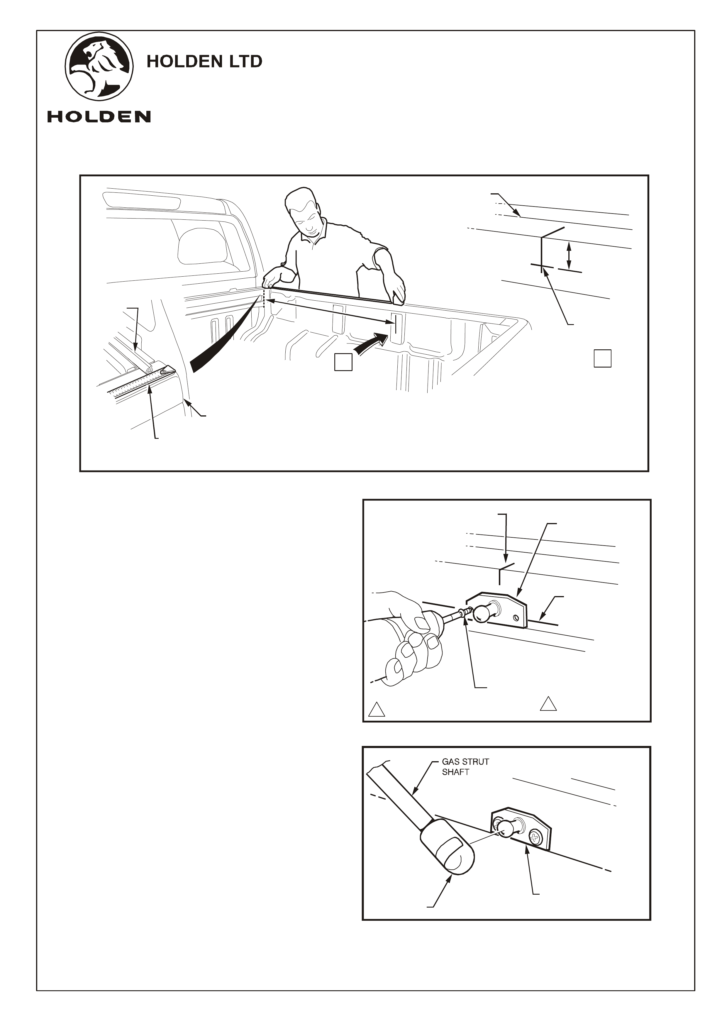
6. Hook a tape measure over the front edge of the
tray and measure 860mm back along the
inside top edge of the tray rail. Mark then
measure down 20mm. Clearly mark the
position. Refer to Figure 6.
7. Align the centre of the strut (tray) bracket
with the 860mm mark and the centre of the
holes with the 20mm mark. Then use the
bracket as a template and drill 2mm dia. pilot
holes (2 places).
8. Vacuum all swarf and paint the holes with
corrosion protection primer.
If a cargo liner is fitted drill through it
and then remove to allow vacuuming of
swarf.
9. Install strut (tray) brackets using self-drilling
screws supplied (2 places) and tighten to
specified torque. Refer to Figure 7.
10. Repeat for the other side.
11. Fit the shaft end of the gas strut onto the ball
screw. A 'click' will be heard when the strut is
seated correctly. Allow the other end of the
strut to lay in the tray. Repeat for other side.
Refer to Figure 8.
NOTE:
FIGURE 6
FIGURE 7
SELF DRILLING
SCREW,
2 PLACES
1-3 Nm
FIGURE 8
11
860MM PEN MARKS
TOP OF
TRAY RAIL
20MM
860MM
MARK STRUT (TRAY)
BRACKET
STRUT (TRAY)
BRACKET
GAS STRUT
SEAL
TAPE
MEASURE
FRONT
EDGE OF
TRAY
20MM
MARK
VIEW
A
A
Page 4 of 7
Division of HOLDEN Ltd ACN 006 893 232
FD1113
07AP04
COPYRIGHT
Reproduction in whole or part
prohibited without written approval
FITTING INSTRUCTIONS FOR
RA RODEO CREW CAB
TONNEAU COVER - HARD TOP
.
.
.
1
1
1-3 Nm
FIGURE 9
STRUT (TONNEAU)
BRACKET
SCREW, 3 PLACES
EACH SIDE
FIGURE 10
12. Remove the gas strut screws from the hard
tonneau and install the gas strut bracket to
the tonneau. Tighten the screws to specified
torque. Repeat for other side.
Refer to Figure 9
13. With the aid of an assistant, install the
tonneau by raising its rear to near 90 and
inserting the hinge tongues into the hinge
slots. Refer to Figure 10.
Take precautions to avoid damage to
the hard tonneau or the vehicle.
FITTING INSTRUCTI ONS: -
continued
o
NOTE:
NEAR 90
o
A
.
.
.
.
.
.
.
.
.
.
.
.
.
.
.
.
.
...
.
.
..
.
.
.
.
.
.
.
.
...
.
.
..
.
.
.
.
.
.
.
.
.
.
.
.
.
.
..
.
.
.
..
.
.
.
.
..
.
.
.
.
..
.
.
.
.
..
.
.
.
.
..
.
.
.
.
.
.
.
.
.
.
.
.
.
.
.
.
.
.
..
.
.
.
.
.
.
.
.
.
.
.
.
.
.
.
.
.
.
.
.
.
.
.
.
.
.
.
.
.
.
.
.
.
.
.
.
.
.
.
.
.
.
.
.
.
..
.
.
.
..
.
.
.
.
.
.
.
.
.
.
.
.
.
.
..
.
.
.
.
..
.
.
.
.
..
.
.
.
.
..
.
.
.
.
.
.
.
.
.
.
.
.
.
.
..
.
.
.
.
.
.
.
.
.
.
...
..
.
.
.
.
.
.
.
.
.
..
.
.
.
.
.
.
.
.
.
.
.
..
.
.
.
.
.
..
..
.
A
VIEW
Page 5 of 7
Division of HOLDEN Ltd ACN 006 893 232
FD1113
07AP04
COPYRIGHT
Reproduction in whole or part
prohibited without written approval
FITTING INSTRUCTIONS FOR
RA RODEO CREW CAB
TONNEAU COVER - HARD TOP
FITTING INSTRUCTI O NS: -
continued
14. Lower the tonneau sufficiently to allow the
gas struts to be attached to the tonneau strut
brackets. A 'click' will be heard when the
strut is seated correctly. Refer to Figure 11.
Ensure the hinge tongues are fully
inserted into the hinge slots.
Ensure the cylinder end of the strut
is attached to the tonneau.
15. Close the tonneau carefully and check its
alignment around each side and the rear.
16. If adjustment is required, open the tonneau
and disconnect the gas struts from the
tonneau by inserting a small screwdriver
under the spring clip on the strut end and
prise the clip outward:
Remove the strut.
17. Loosen the screws attaching each hinge to
the tonneau with a 5mm Allen key. Open the
end gate and have an assistant lie in the tray
on their back with the Allen key.
18. Close the tonneau and manouevre it into the
correct position. When correctly aligned
each side and rear, have the assistant
tighten the hinge screws to specified torque .
Refer to Figure 12.
19. Refit the gas struts to the tonneau.
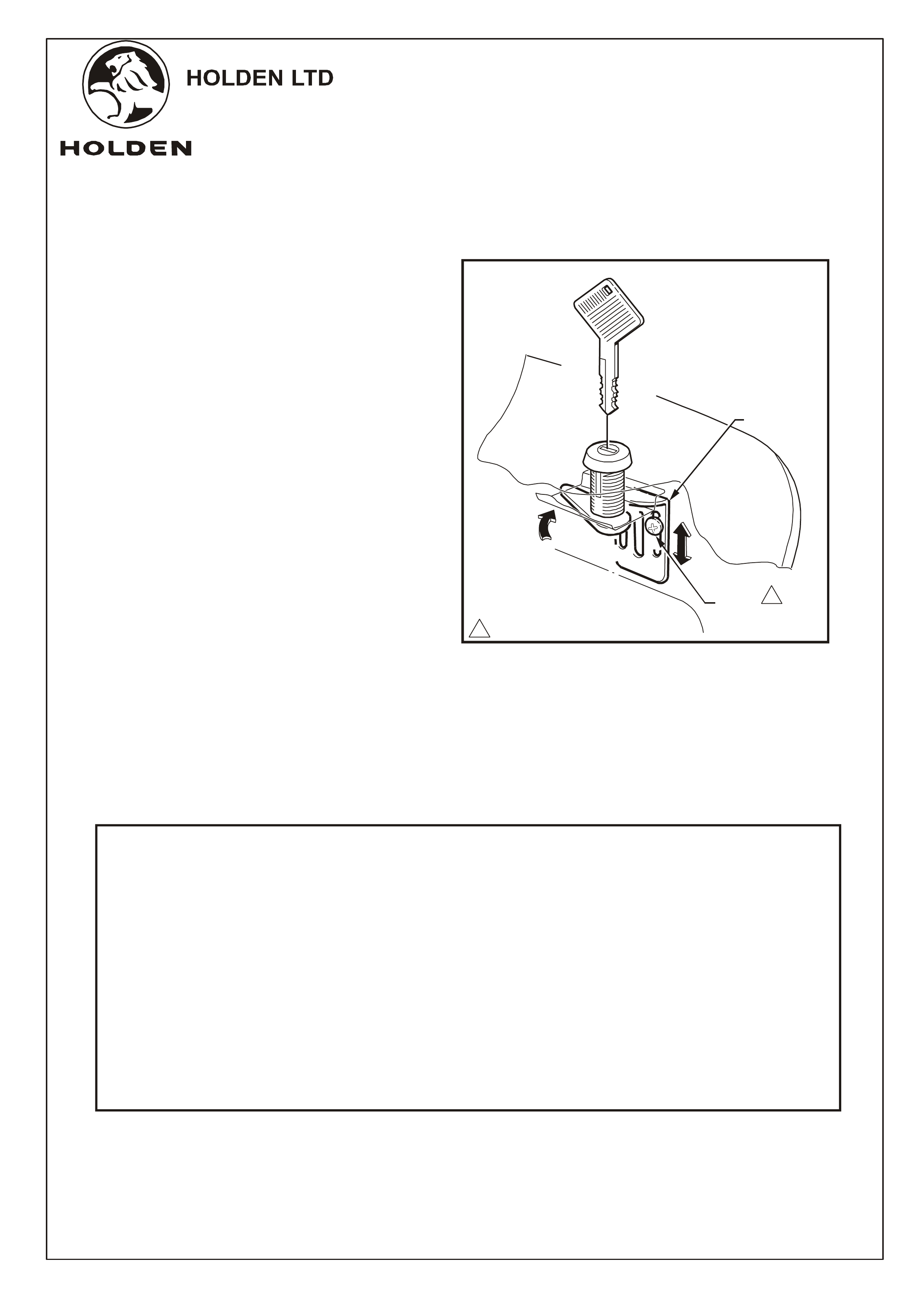
20. To fit the lock plates, lie in the tray with the
hard tonneau closed and the locks in the
locked position. Align the lock plate with the
locking tab and using the lock plate as a
template mark where to drill 2mm dia. pilot
holes. Remove the lock plate, drill the holes
vacuum up any swarf and paint the holes
with corrosion protection primer. Fit the lock
plate using the self drilling screws (2 places)
provided. Tighten screws to specified torque.
Refer to Figures 13 and 14.
NOTE 1:
NOTE 2:
DO NOT REMOVE
THE SPRING CLIP.
FIGURE 11
FIGURE 12
A
LLEN HEAD SCREW,
4 PLACES
1
1
1-3 Nm
GAS STRUT
FIGURE 13
GAS STRUT
CYLINDER
SELF DRILLING
SCREW (2 PLACES)
1
1
1 - 2 Nm
LOCK PLATE
DRILL 2mm
DIA HOLE
Page 6 of 7
Division of HOLDEN Ltd ACN 006 893 232
FD1113
07AP04
COPYRIGHT
Reproduction in whole or part
prohibited without written approval
FITTING INSTRUCTIONS FOR
RA RODEO CREW CAB
TONNEAU COVER - HARD TOP
FITTING INSTRUCTI ONS: -
continued
21. Close the tonneau and check the locking
action on each side. Raise or lower the lock
plates until slight contact pressure with the
locking plate can be felt. When operating the
lock this slight pressure is required for the
locks to operate correctly. Torque screws to
specified Torque. Refer to Figure 14.
22. Place the fitting instructions and locking keys
in vehicle's glove box.
FIGURE 14
LOCK PLATE
HAVING TROUBLE? PHONE FREECALL 1800 226679
SCREW
(2 PLACES)
1
1
1 - 2 Nm
PART NO. DESCRIPTION QUANTITY
VARIOUS TONNEAU COVER 1
FRONT BAR ASSEMBLY 1
M6 X 20 SCREWS (IF REQUIRED) 5
SCREWS - SELF DRILLING 10
92146786 GAS STRUT 2
STRUT (TRAY) BRACKET 2
STRUT (TONNEAU) BRACKET 2
LOCK PLATE 2
FD1113 TONNEAU COVER - HARD TOP FITTING INSTRUCTIONS 1
LOCK - PAIR 1
FD796 PROOF OF WARRANTY CARD 1
PARTS LIST
Page 7 of 7
Division of HOLDEN Ltd ACN 006 893 232
FD1113
07AP04
COPYRIGHT
Reproduction in whole or part
prohibited without written approval
FITTING INSTRUCTIONS FOR
RA RODEO CREW CAB
TONNEAU COVER - HARD TOP