FD1203
01JUL04
HOLDEN LTD
Division of HOLDEN Ltd ACN 006 893 232
FITTING INSTRUCTIONS FOR
RA MOBILE PHONE PATCH HARNESS
COPYRIGHT
Reproduction in whole or part
prohibited without written approval
COPYRIGHT
Page 1 of 4
Reproduction in whole or part
prohibited without written approval
Part No. 92147932
FIGURE 1
IMPORTANT:
The mobile phone patch harness is supplied fitted
with a 6-pin connector. This connector can be used
with the Holden mobile phone connector (92175840)
or removed and replaced with the customer's mobile
phone hands free package.
Fitting the connector from the customers hands free
phone kit to the mobile phone patch harness should
be carried out by a competent person, if in doubt
seek professional assistance.
TOOLS REQUIRED:
10 mm spanner or socket.
FITTING INSTRUCTIONS:
1. If required, remove the existing 6-pin connector from the
mobile phone patch harness and install the customers
new hands free phone kit connector onto the mobile
phone patch harness. Wire new connector according to
manufacturers wiring specifications.
NOTE: For mobile phone patch harness wiring
information, refer to table on Page 4.
2. Turn vehicles ignition to the "OFF" position.
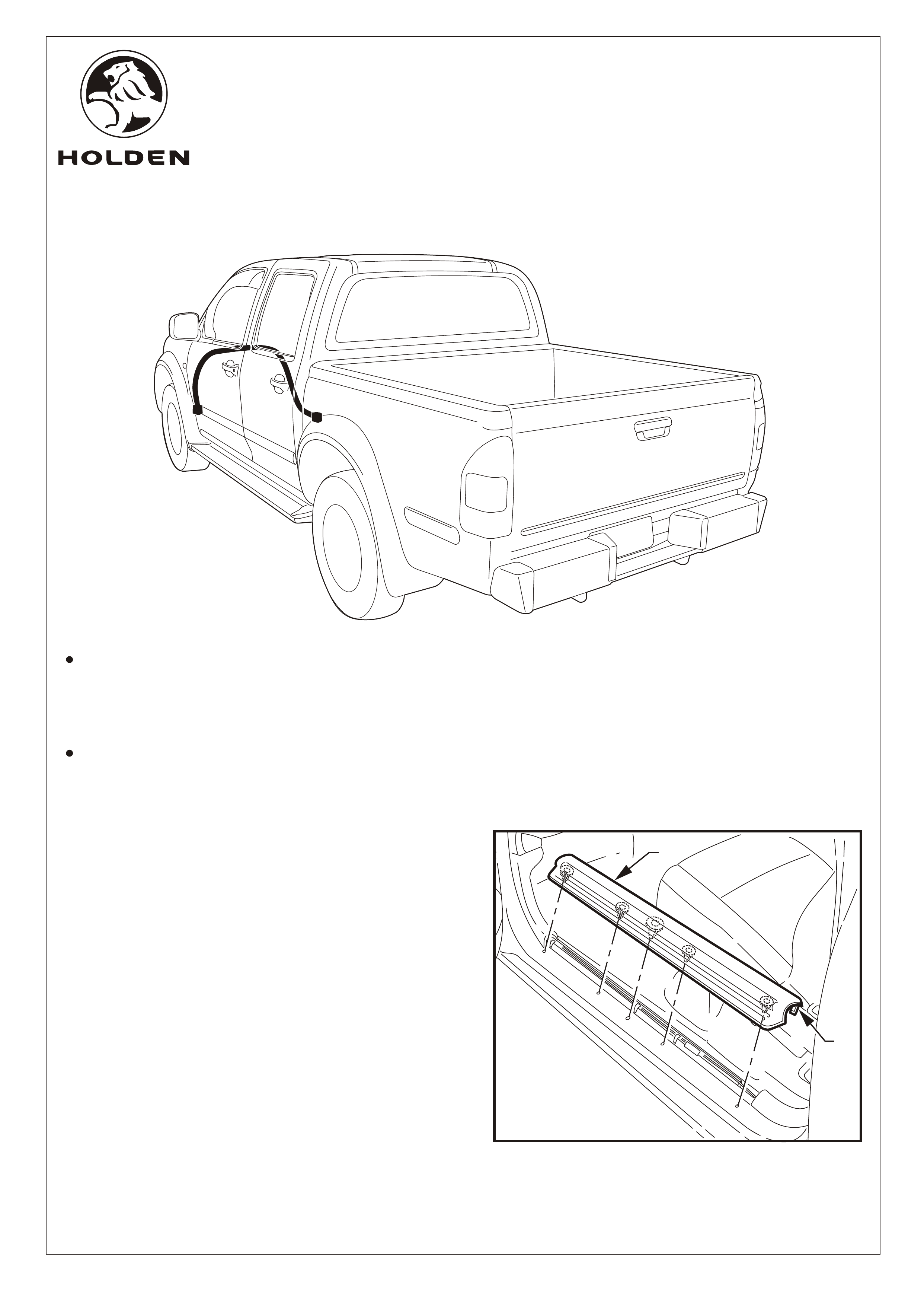
3. Open the passenger door and remove the front side sill
trim (1) by pulling upwards. Refer to Figure 1.
NOTE: Flare out both ends of the trim when pulling up to
prevent breaking off the retaining lugs (2).
1
2
FD1203
01JUL04
HOLDEN LTD
Division of HOLDEN Ltd ACN 006 893 232
FITTING INSTRUCTIONS FOR
RA MOBILE PHONE PATCH HARNESS
COPYRIGHT
Reproduction in whole or part
prohibited without written approval
Page 2 of 4
FITTING INSTRUCTIONS: Continued...
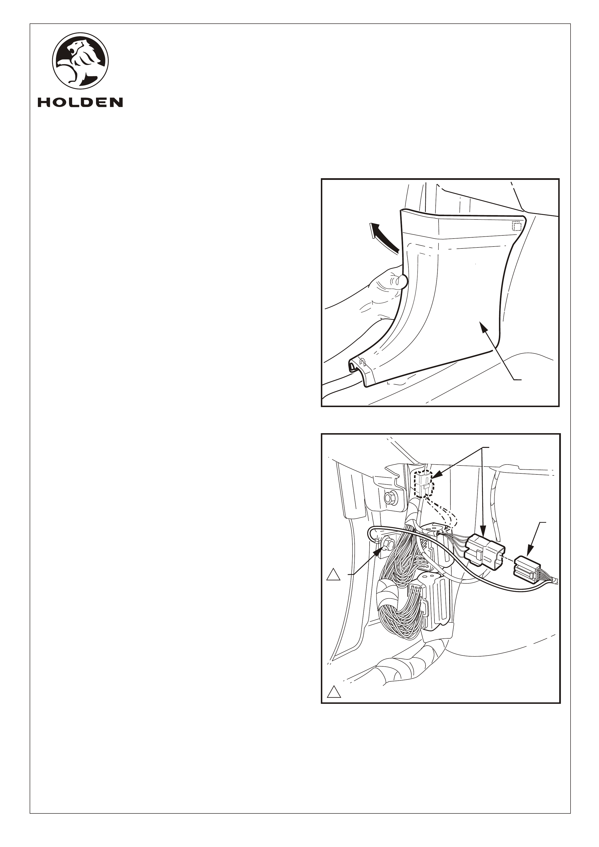
Connect the mobile phone patch harness (2) (with the
customer's hands free phone kit wiring connector fitted)
into the breakout connector.
7. Remove the fastener (3), place ring terminal on the
fastener and replace. Tighten the fastener to the
specified torque.
4. Pull up and back to remove side kick plate trim. Refer to
Figure 2.
Refer to Figure 3 for the following:
5. The vehicle harness connecter block (1) for the mobile
phone is taped back to the vehicle body harness, break
the tape to release the connecter block.
6.
FIGURE 2
1
FIGURE 3
1
3
2
10.0 Nm
1
1
FD1203
01JUL04
HOLDEN LTD
Division of HOLDEN Ltd ACN 006 893 232
FITTING INSTRUCTIONS FOR
RA MOBILE PHONE PATCH HARNESS
COPYRIGHT
Reproduction in whole or part
prohibited without written approval
Page 3 of 4
FITTING INSTRUCTIONS: Continued...
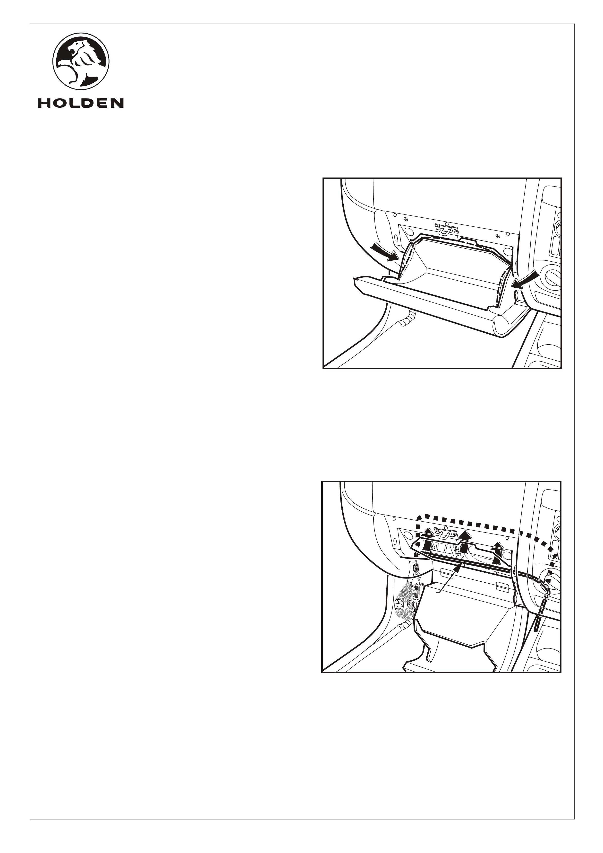
7. Open the glovebox and apply pressure to the sides of
the glovebox to bend the sides enough to allow the
sides to come out past the glovebox travel limiting lugs.
Refer to Figure 4.
8. Loop the patch harness (1) up and over the back of the
glovebox cavity. Refer to Figure 5.
FIGURE 5
FIGURE 4
2
FD1203
01JUL04
HOLDEN LTD
Division of HOLDEN Ltd ACN 006 893 232
FITTING INSTRUCTIONS FOR
RA MOBILE PHONE PATCH HARNESS
COPYRIGHT
Reproduction in whole or part
prohibited without written approval
FITTING INSTRUCTIONS: Continued...
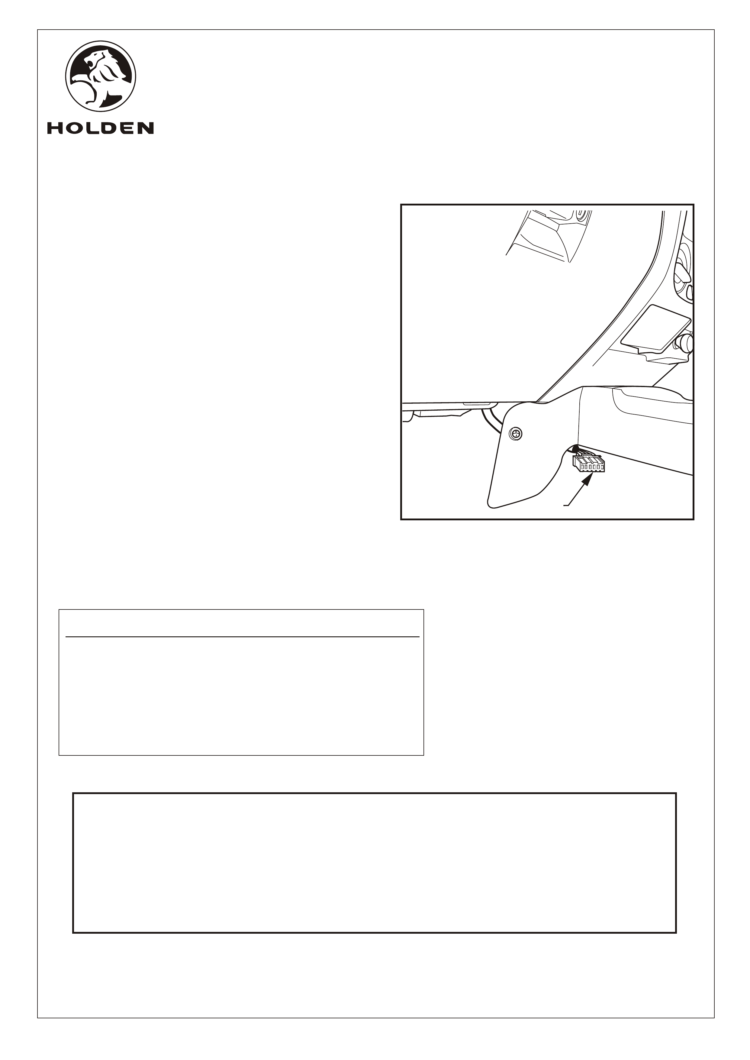
9.
ushed under
the fascia of the centre console and
Refer to Figure 6.
10. Check that the patch harness dose not interfere with the
operation of the glovebox and heating mechanisms. If
necessary reposition the patch harness.
11. Use cable ties supplied to tie back the patch harness at
suitable points to prevent the harness from dropping
down into the cabin area.
12. Reinstall all parts removed in reverse order.
13. Put the fitting instructions in the vehicles glove box.
The end of the mobile phone patch harness fitted with
the 6-pin Holden connector or the customers hands free
phone kit wiring connector (1) should be p
position for easy
access.
RODEO MOBILE PHONE HARNESS PACKAGE
PARTS LIST
PART NUMBER DESCRIPTION QUANTITY
92147932 MOBILE PHONE PATCH HARNESS PACKAGE 1
STRAP - TIE HARNESS 4
FD796 PROOF OF WARRANTY CARD 1
FD1203 FITTING INSTRUCTIONS 1
FIGURE 6
Page 4 of 4
1
Pin No. Description Wire Colour
1 Permanent Power (+ve 12V) Red
2 Ground Black
3 Accessory Power (+ve 12V) Yellow
4 Radio Mute Signal Pink
5 Audio Signal (+ve) Blue
6 Audio Signal (-ve) Brown
Illumination (+ve 12V) Green (Loose)