FD1213
04MY04
HOLDEN LTD
Division of HOLDEN Ltd ACN 006 893 232
COPYRIGHT
Reproduction in whole or part
prohibited without written approval
COPYRIGHT
Reproduction in whole or part
prohibited without written approval
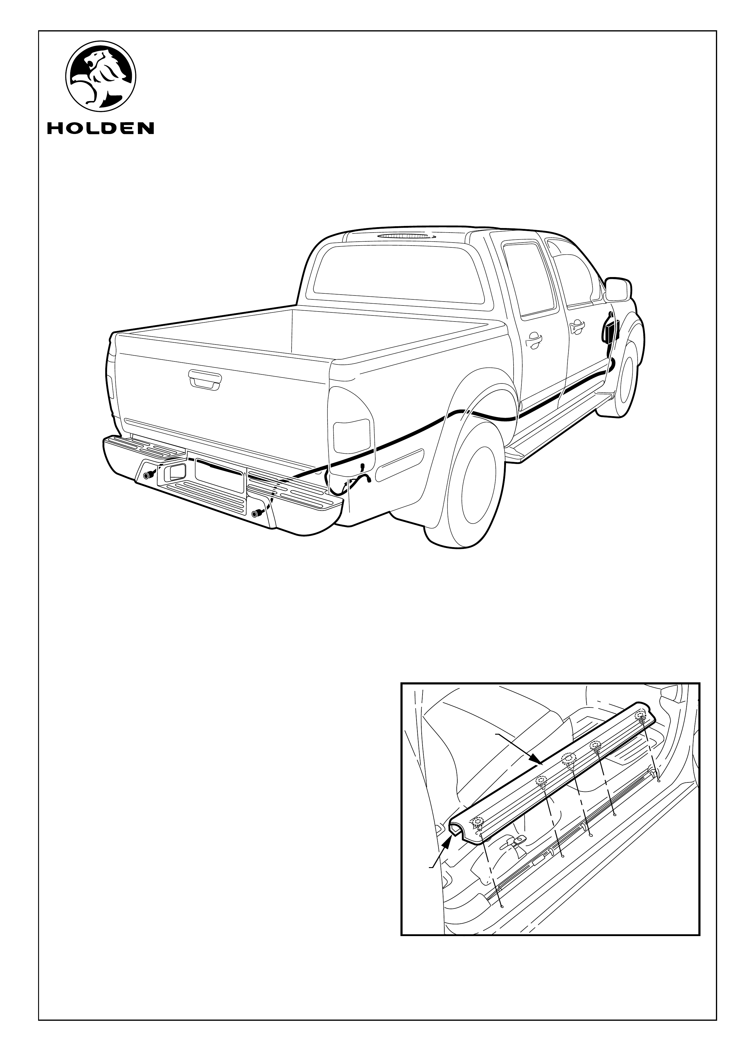
FITTING INSTRUCTIONS FOR RA LT RODEO
REVERSE PARKING SENSOR SYSTEM
Page 1 of 14
Part No. 92148173
TOOLS REQUIRED:
Power Drill, 32mm Hole Saw & Arbor, 2mm Drill Bit, 22mm
Spade Drill Bit, 17mm Socket, 10 mm Socket, Torque
Wrench, Large Bull Nose Pliers, Half Round File, Side
Cutters, Forked Tongue Service Tool (Recommended), Two
Post Vehicle Hoist (Recommended), Masking Tape.
FITTING INSTRUCTIONS:
1. Turn vehicles ignition to the "OFF" position.
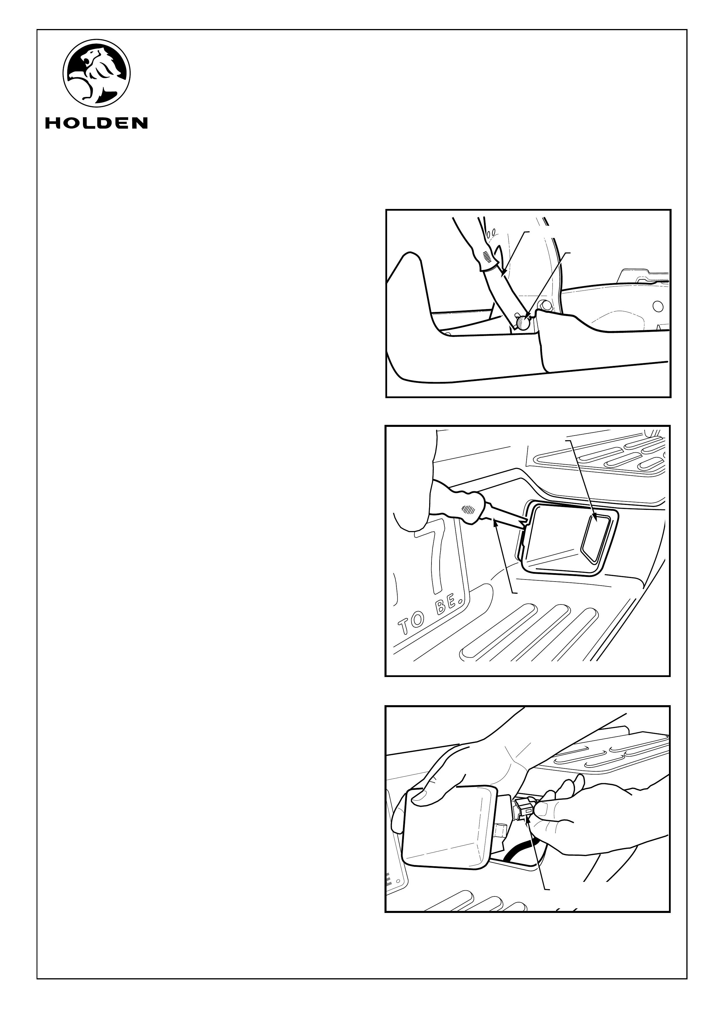
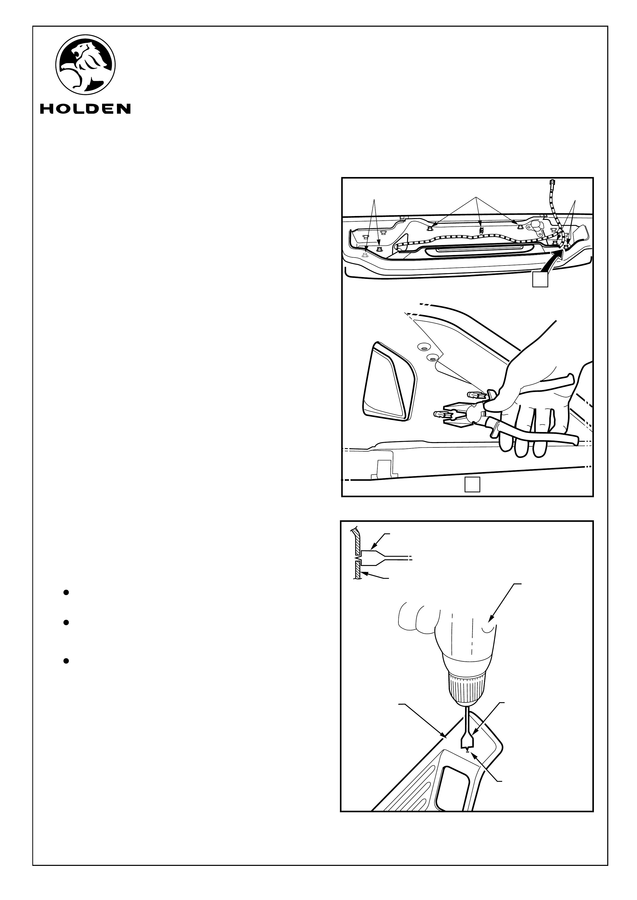
2. Open the drivers door and remove the front side seals by
pulling upwards. Refer to Figure 1.
NOTE: Flare out both ends of the trim when pulling up to
prevent breaking off the retaining lugs (2).
FIGURE 1
SIDE
SILL
LUG
FD1213
04MY04
HOLDEN LTD
Division of HOLDEN Ltd ACN 006 893 232
COPYRIGHT
Reproduction in whole or part
prohibited without written approval
COPYRIGHT
Reproduction in whole or part
prohibited without written approval
FITTING INSTRUCTIONS FOR RA LT RODEO
REVERSE PARKING SENSOR SYSTEM
Page 2 of 14
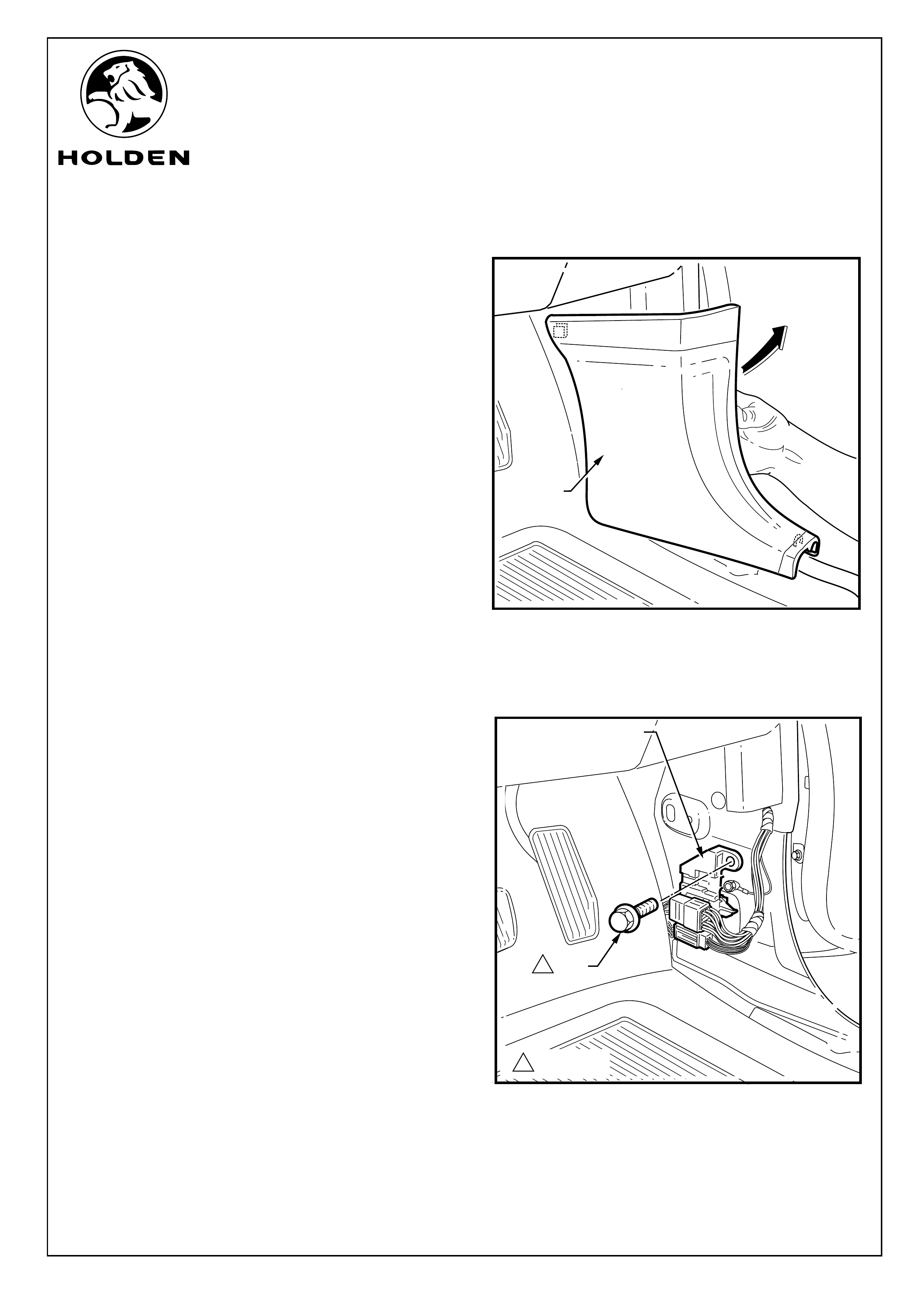
FITTING INSTRUCTIONS: - continued...
3. Pull up and back to remove side kick plate trim. Refer to
Figure 2.
4. Use a 10mm socket to remove the bolt retaining the
connector holder. Refer to Figure 3.
BOLT
FIGURE 2
FIGURE 3
CONNECTER
HOLDER
KICK
TRIM
12.0 ~ 3.0 Nm
1
FD1213
04MY04
HOLDEN LTD
Division of HOLDEN Ltd ACN 006 893 232
COPYRIGHT
Reproduction in whole or part
prohibited without written approval
COPYRIGHT
Reproduction in whole or part
prohibited without written approval
FITTING INSTRUCTIONS FOR RA LT RODEO
REVERSE PARKING SENSOR SYSTEM
Page 3 of 14
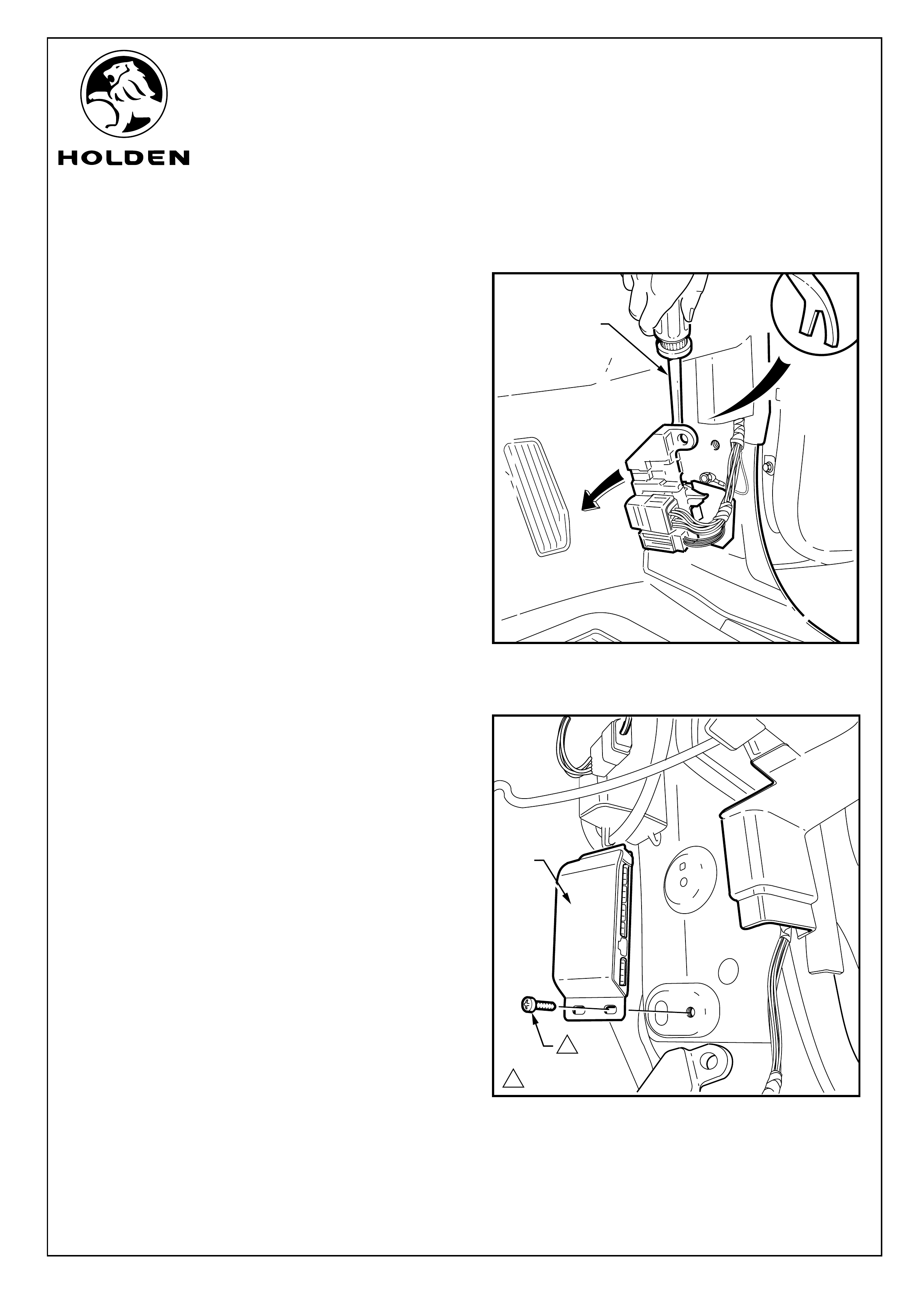
TRIM
REMOVER
FIGURE 4
FITTING INSTRUCTIONS: - continued...
control unit with the threaded hole and u
5. Detach the connector holder with the aid of forked
tongue service tool. Refer to Figure 4.
Refer to Figure 5.
6. Align the se the
bolt supplied to fix the control unit to the vehicle. Tighten
to specified torque.
FIGURE 5
12.0 ~ 3.0 Nm
CONTROL
UNIT
BOLT
1
FD1213
04MY04
HOLDEN LTD
Division of HOLDEN Ltd ACN 006 893 232
COPYRIGHT
Reproduction in whole or part
prohibited without written approval
COPYRIGHT
Reproduction in whole or part
prohibited without written approval
FITTING INSTRUCTIONS FOR RA LT RODEO
REVERSE PARKING SENSOR SYSTEM
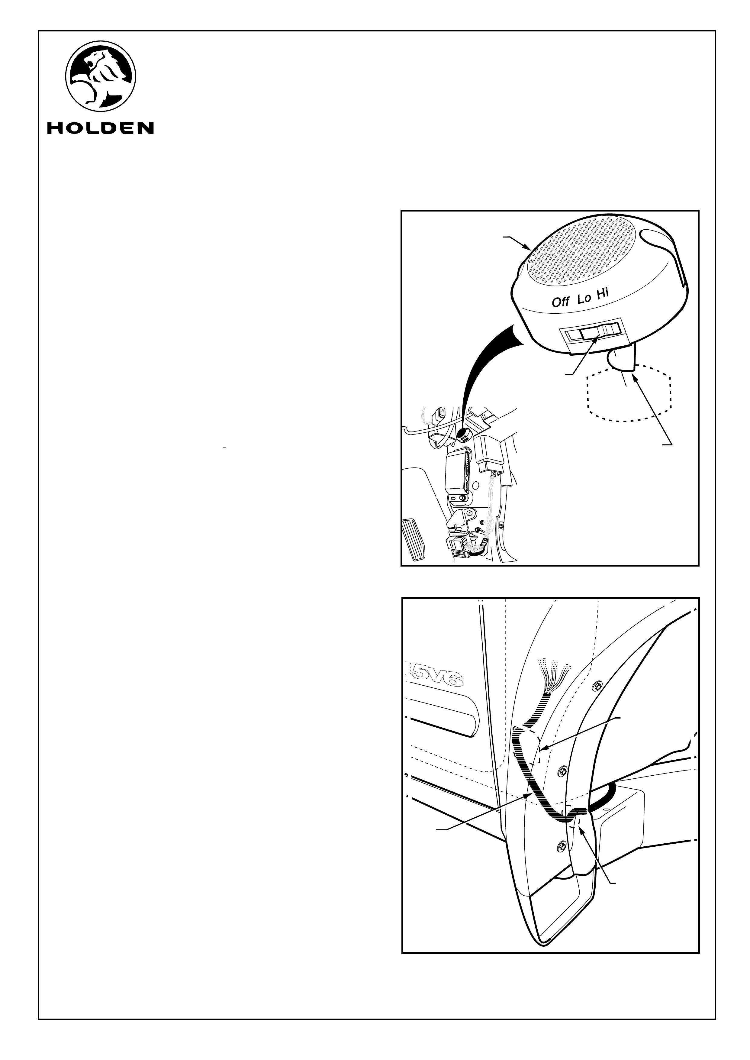
RPA
BUZZER
SWITCH SET
TO 'Hi' POSITION
FITTING INSTRUCTIONS: - continued...
Refer to Figure 6 for the following:
7. Use high-tech cleaning pad supplied to clean RPS
buzzer mounting area at the location shown on the inner
right-hand side reinforcing panel. Retain cleaning pad
for further use.
8. Remove protective backing from RPS buzzer and attach
buzzer into position at the location shown. Press RPS
buzzer firmly onto the panel for at least ten seconds to
ensure permanent adhesion is achieved.
NOTE: The RPS buzzer is attached onto the panel with
the socket facing up.
9. Set the RPS buzzer to the Li position.
Refer to Figure 7 for the following:
10. Remove the grommet at the rear inner side face of the
right hand side wheel well.
11.Tape the RPS harness to a guide wire approximately
600mm long, stagger the connectors to keep the join as
thin as possible.
12. Pass the guide wire into the grommet hole and direct it
up and into the foot well of the vehicle.
13. Manipulate the harness through the grommet hole and
into the foot well of the vehicles, when the grommet on
the harness is up against the grommet hole push the
grommet in; make sure the grommet is completely
home.
FIGURE 7
Page 4 of 14
GROMMET
HOLE
RPA
HARNESS
FOOT WELL
APERTURE
PROTECTIVE
BACKING
11
FIGURE 6
FD1213
04MY04
HOLDEN LTD
Division of HOLDEN Ltd ACN 006 893 232
COPYRIGHT
Reproduction in whole or part
prohibited without written approval
COPYRIGHT
Reproduction in whole or part
prohibited without written approval
FITTING INSTRUCTIONS FOR RA LT RODEO
REVERSE PARKING SENSOR SYSTEM
FITTING INSTRUCTIONS: - continued...
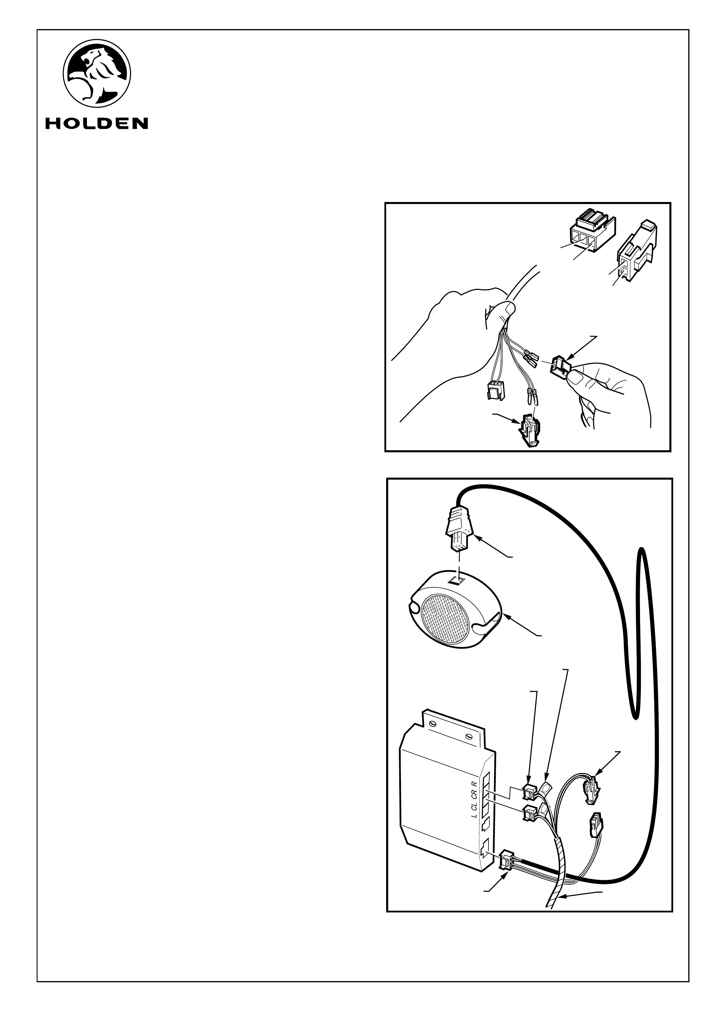
Refer to Figure 8 for the following:
14. Remove tape and guide wire from RPS main harness.
15. Connect tagged RPS main harness wire terminals to the
3-way female connectors supplied, according to table
below:
16. Connect two remaining male terminal wires into the two
way female connector supplied, according to table
below:
PIN 1 PIN 2
Buzzer/Power BK RD
NOTE Wire colours are:
BN - BROWN
BL - BLUE
GN - GREEN
WH - WHITE
BK - BLACK
RD - RED
Refer to Figure 9 for the following:
17. Connect the RPS main harness module connectors into
their corresponding positions in the RPS module
(2 places).
18. Connect the 2-Way power supply connector from the
RPA patch harness to the 2-Way RPS buzzer/power
lead connector.
19. Connect the 2 Way RPS buzzer lead connector into the
RPS buzzer.
20. Connect RPS buzzer lead connector to the RPS buzzer.
PIN 1 PIN 2 PIN 3
Centre Left N/A BN BL
Centre Right N/A GN WH
__CONNECTOR
IDENTIFICATION
POWER
SUPPLY
CONNECTOR
2-WAY
MAIN HARNESS TO
MODULE CONNECTORS
3-WAY
RPA BUZZER
CONNECTOR
4-WAY
FIGURE 9
MAIN RPS
HARNESS
CL
CR
BUZZER
RPS BUZZER
CONNECTOR
2-WAY
2
3
1
1
2
FEMALE 3-WAY
MAIN HARNESS TO
MODULE CONNECTOR
(2 PLACES)
FEMALE 2-WAY
POWER SUPPLY
CONNECTOR
P2
P3
P1
P2
FIGURE 8
Page 5 of 14
FD1213
04MY04
HOLDEN LTD
Division of HOLDEN Ltd ACN 006 893 232
COPYRIGHT
Reproduction in whole or part
prohibited without written approval
COPYRIGHT
Reproduction in whole or part
prohibited without written approval
FITTING INSTRUCTIONS FOR RA LT RODEO
REVERSE PARKING SENSOR SYSTEM
FITTING INSTRUCTIONS: - continued...
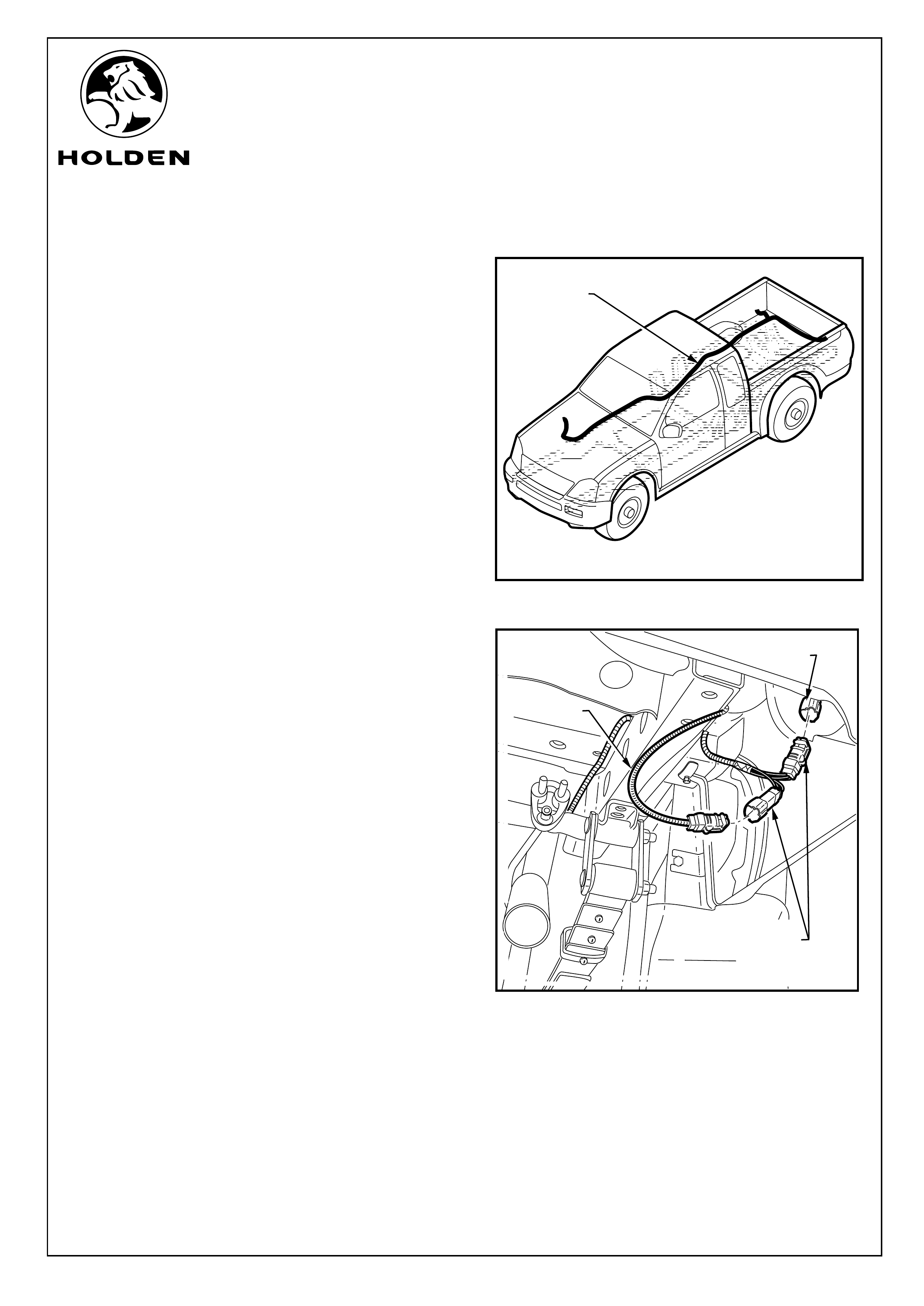
21. Feed RPS harness along the outside top edge of the
vehicle's right hand main chassis rail to the end of the
vehicle's cab. Pass the RPS harness over the top of the
chassis rail and continue feeding the harness to the rear
of the vehicle. Refer to Figure 10.
IMPORTANT: Make sure the harness is well away
from the exhaust system and any suspension parts.
22. Disconnect the RHS body to RHS tail lamp connector
and plug the male connector from the patch harness into
the female tail lamp connecter and the female patch
harness connector into the male body harness. Refer to
Figure 11.
FIGURE 10
FIGURE 11
Page 6 of 14
RPS PATCH
HARNESS
LAMP
HARNESS
BODY
HARNESS
PATC H
HARNESS
CONNECTERS
FD1213
04MY04
HOLDEN LTD
Division of HOLDEN Ltd ACN 006 893 232
COPYRIGHT
Reproduction in whole or part
prohibited without written approval
COPYRIGHT
Reproduction in whole or part
prohibited without written approval
FITTING INSTRUCTIONS FOR RA LT RODEO
REVERSE PARKING SENSOR SYSTEM
1
150 Nm
MASKING
TAPE
BUMPER
FASCIA
TEMPLATE
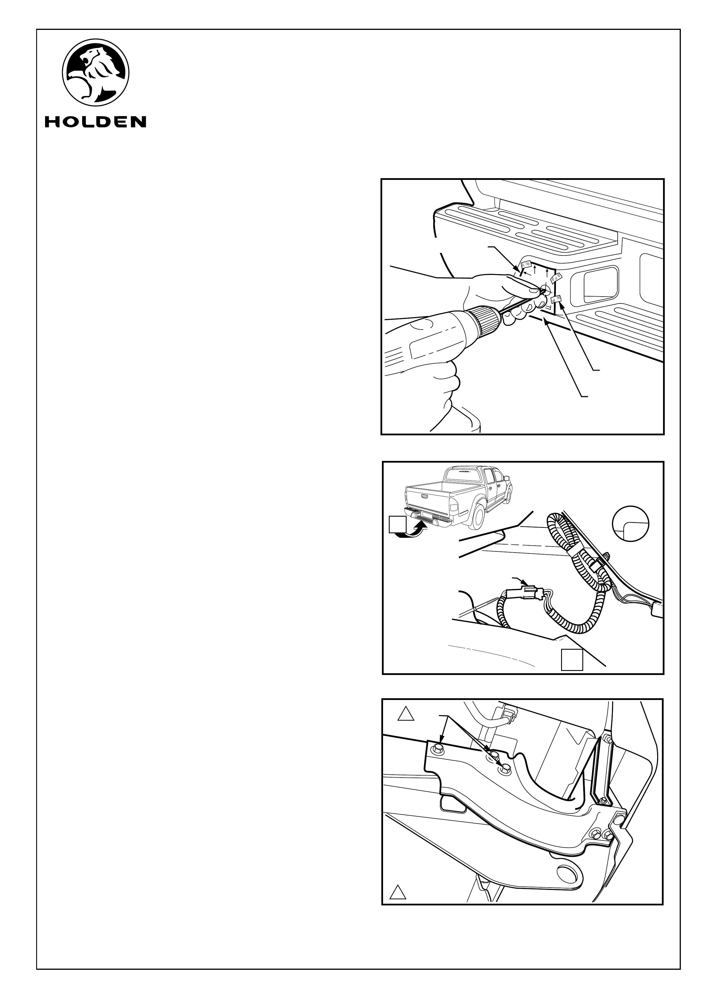
FITTING INSTRUCTIONS: - continued...
Refer to Figure 12 for the following:
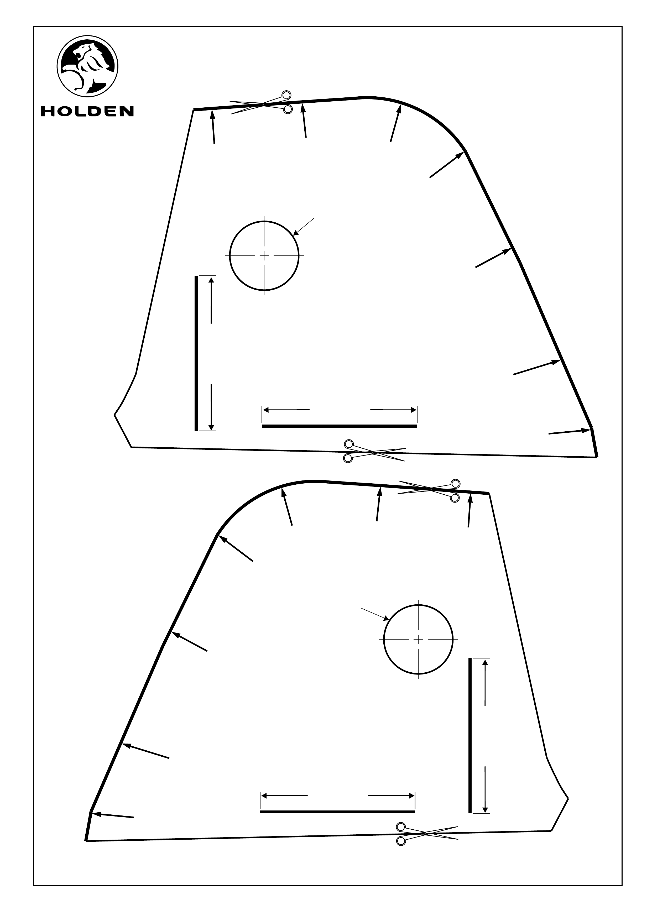
23. Use a ruler to check that the scale on the template on the
back page of this instructions is correct. Cut out the two
templates and position them on the black bumper fascia
as indicated on the template. Use masking tape to hold
in position.
24. Using a 2.0 mm drill bit to drill a pilot holes through the
templates and fascia (2 places). Ensuring that the drill is
square to the bumper fascia and continue to drill into the
Steel bumper behind fascia to mark the hole position do
not drill through bumper. Refer to Figure 12.
CAUTION: The bumper is chromed so the drill may
wonder if the pressure applied to the drill is not
square to the bumper.
25. Remove the templates.
26. Disconnect the body harness to rear bumper assembly
connecter and pass the bumper harness connecter back
through the vehicle body aperture. Refer to Figure 13.
Refer to Figure 14 for the following:
27. Use a 17mm socket to remove the 6 bolts that hold the
rear bumper assembles to the vehicle, (three on each
side).
28. Lower and draw back the bumper assembly from the
vehicle.
29. Place bumper assembly on a solid, soft, clean surface.
FIGURE 12
Page 7 of 14
FIGURE 13
FIGURE 14
BOLT
1
A
VIEW A
BODY/BUMPER
HARNESS CONNECTER
FD1213
04MY04
HOLDEN LTD
Division of HOLDEN Ltd ACN 006 893 232
COPYRIGHT
Reproduction in whole or part
prohibited without written approval
COPYRIGHT
Reproduction in whole or part
prohibited without written approval
FITTING INSTRUCTIONS FOR RA LT RODEO
REVERSE PARKING SENSOR SYSTEM
FITTING INSTRUCTIONS: - continued...
30. Use a trim remover to remove the tree clips (2 places)
from the underside of the bumper assembly. Refer to
Figure 15.
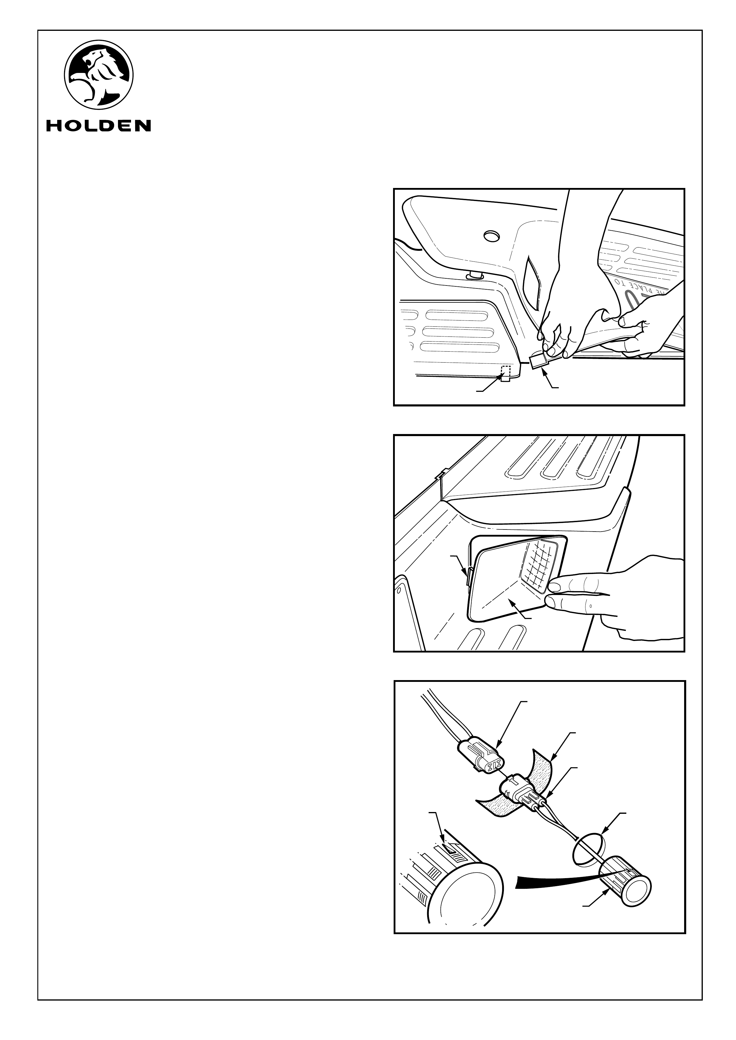
31. Slide the trim remover tool in between the bumper fascia
and the light assembly to release each of the number
plate illumination lights. Refer to Figure 16.
32. Disconnect the bumper harness from the number plate
lights and place the to one side. Refer to Figure 17.
TRIM REMOVAL TOOL
Page 8 of 14
FIGURE 15
FIGURE 16
FIGURE 17
TRIM REMOVAL TOOL
TREE CLIP
NUMBER PLATE LIGHT
NUMBER PLATE
LIGHT CONNECTER
FD1213
04MY04
HOLDEN LTD
Division of HOLDEN Ltd ACN 006 893 232
COPYRIGHT
Reproduction in whole or part
prohibited without written approval
COPYRIGHT
Reproduction in whole or part
prohibited without written approval
FITTING INSTRUCTIONS FOR RA LT RODEO
REVERSE PARKING SENSOR SYSTEM
FITTING INSTRUCTIONS: - continued...
33. Use a large pair of bullnose pliers to squeeze the lugs (7
places) retaining the bumper fascia, ensue that all the
bumper lugs are released, then slowly work lugs through
to release the bumper fascia from the chromed steel
bumper. Refer to Figure 18.
IMPORTANT: Take extreme care not to use force
when removing the fascia to prevent the retaining
lugs from breaking off as this will render the fascia
unserviceable.
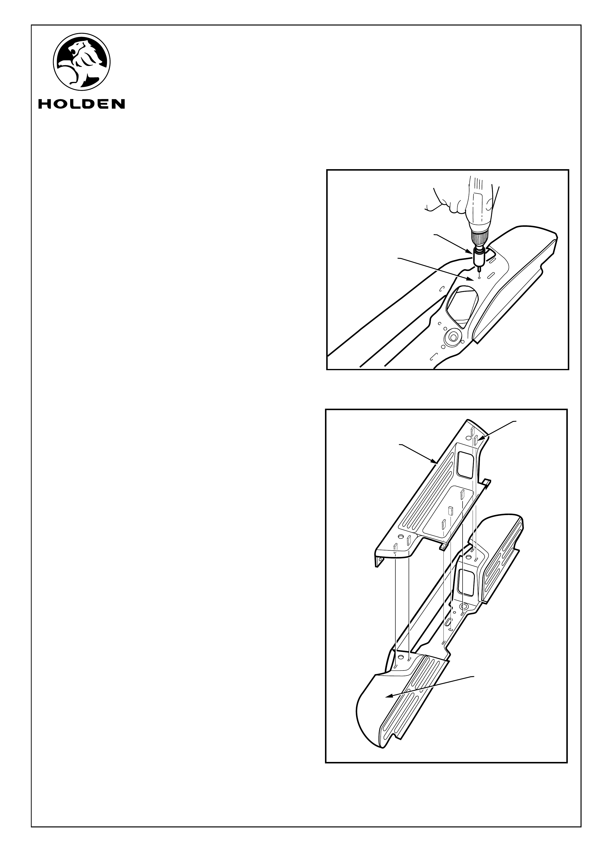
34. Support the bumper fascia and use a 22mm wood spade
drill to open out the two pilot holes in the fascia. Refer to
Figure 19.
IMPORTANT:
Use a wood spade drill bit only as a normal drill bit
or hole saw may damage the bumper fascia.
Ensure the spade drill bit remains square with the
bumper fascia.
Use a slow drill speed only to avoid damaging the
bumper fascia.
BUMPER
FASCIA
ENSURE DRILL BIT REMAINS
SQUARE WITH BUMPER FASCIA
BUMPER FASCIA
22
2222
SLOW
DRILL
SPEED
22mm DIA. WOOD
SPADE DRILL BIT
2mm PILOT HOLE
Page 9 of 14
FIGURE 18
FIGURE 19
VIEW A
A
LUGS LUGS LUGS
FD1213
04MY04
HOLDEN LTD
Division of HOLDEN Ltd ACN 006 893 232
COPYRIGHT
Reproduction in whole or part
prohibited without written approval
COPYRIGHT
Reproduction in whole or part
prohibited without written approval
FITTING INSTRUCTIONS FOR RA LT RODEO
REVERSE PARKING SENSOR SYSTEM
HOLE SAW BIT
FITTING INSTRUCTIONS: - continued...
35. Support the bumper on it's back at both ends centre
punch the marks made by the 2mm drill to prevent the
arbor drill of the hole saw drifting off the mark. Refer to
Figure 21.
36. Fit a 32 mm hole saw in the drill and drill out the two holes
marked (one each side). Use a file to remove burs.
37. Place the bumper fascia over the bumper and align the
fascia lugs with their corresponding slots. Refer to
Figure 22.
FIGURE 21
FIGURE 22
BUMPER
FASCIA
SEVEN
FITTING
LUGS
CHROME BUMPER
CHROME
BUMPER
Page 10 of 14
FD1213
04MY04
HOLDEN LTD
Division of HOLDEN Ltd ACN 006 893 232
COPYRIGHT
Reproduction in whole or part
prohibited without written approval
COPYRIGHT
Reproduction in whole or part
prohibited without written approval
FITTING INSTRUCTIONS FOR RA LT RODEO
REVERSE PARKING SENSOR SYSTEM
FITTING INSTRUCTIONS: - continued...
38. Apply pressure to back of the fascia to direct the tabs on
the ends of the fascia to locate into the slots behind the
back lip of the bumper step treads. Ensure lugs are still
aligned and gently push home the bumper fascia. Refer
to Figure 23.
39. Fit the two new tree clips supplied in the kit through the
holes in the tabs of the fascia securing them to the under
side of the bumper. Refer to figure 15.
40. Reconnect the two number plate lamps to the bumper
harness and reinstall into the bumper fascia. Refer to
Figure 24.
Refer to Figure 25 for the following:
41. Insert the two RPS sensor into the fascia with the arrow
facing the top of the bumper. Press fit the sensors to sit
flush with the fascia.
42. Peel protective backing off the foam strips supplied and
wrap strip firmly around each of the sensor connectors.
43. With the aid of an assistant, align rear bumper fascia to
be received by the rear body paneling and connect each
of the sensor connectors to its corresponding RPS
harness connector.
IMPORTANT: Ensure that connectors are fully
engaged.
RPA MAIN HARNESS
CONNECTOR
SENSOR
CONNECTOR
FOAM STRIP
(WRAP AROUND
CONNECTOR)
'TOP'
MARK
Page 11 of 14
FIGURE 24
FIGURE 25
SLOT TAB
FIGURE 23
NUMBER
PLATE
LIGHT
CLIP
SENSOR
22mm DIA.
BUMPER
FASCIA
HOLE
FD1213
04MY04
HOLDEN LTD
Division of HOLDEN Ltd ACN 006 893 232
COPYRIGHT
Reproduction in whole or part
prohibited without written approval
COPYRIGHT
Reproduction in whole or part
prohibited without written approval
FITTING INSTRUCTIONS FOR RA LT RODEO
REVERSE PARKING SENSOR SYSTEM
FITTING INSTRUCTIONS: - continued...
44. Refit the bumper assembly to the vehicle and tighten
bolts to the specified torque. Refer to Figure 14.
45. Pass the bumper harness connecter through the vehicle
body aperture and reconnect to the body harness. Refer
to Figure 13.
46. Fit cable ties approximately 400mm apart along the
length of the RPA patch harness to secure the harness to
the vehicle. Refer to Figure10.
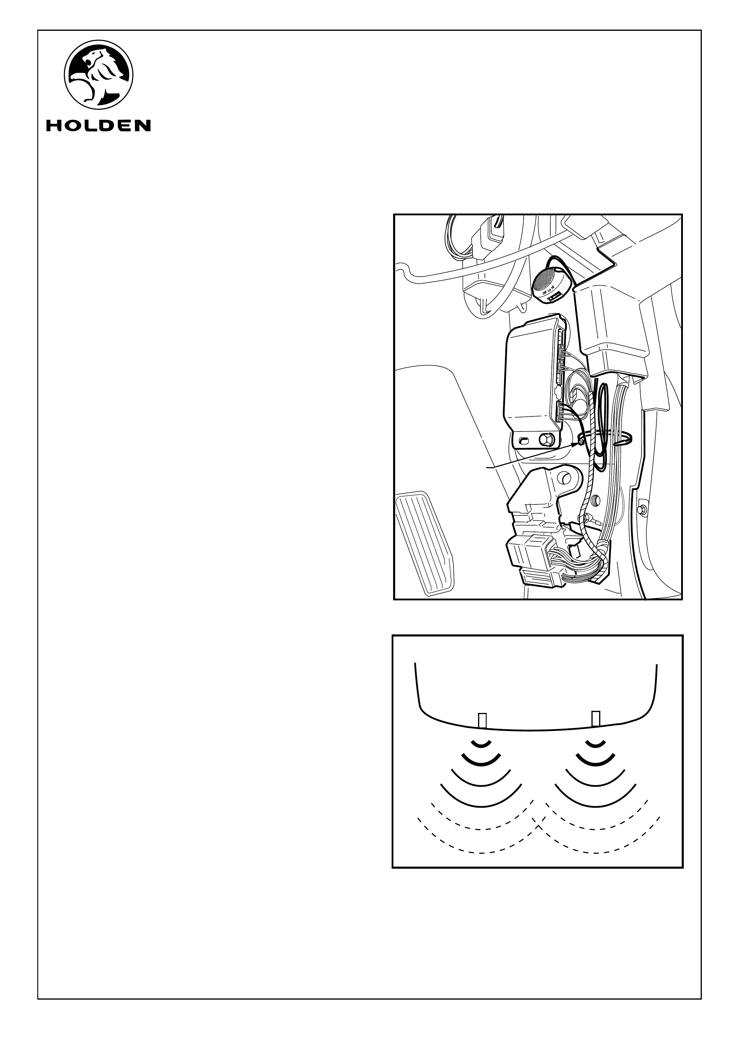
47. Gather surplus wire up in foot well and cable tie to
vehicle body harness. Refer to Figure 26.
48. Test the reverse parking sensor system for correct
operation as follows:
a. Turn the ignition to the "ON" position (engine not
running).
b. Place the gear lever in reverse "R". Two beeps from
the buzzer should be heard indicating the system is
activated.
c. From behind the vehicle, walk towards each sensor.
d. The sensors have 3 stages. Refer to Figure 27.
Refer to Owner’s Handbook for further information
and trouble shooting.
49. Turn the ignition to the "OFF" position and put the vehicle
back into park.
50. Refit all removed parts in the reverse order to removal.
51. Place fitting instructions in the glovebox.
1
Page 12 of 14
FIGURE 26
FIGURE 27
CABLE TIE

FD1213
04MY04
HOLDEN LTD
Division of HOLDEN Ltd ACN 006 893 232
COPYRIGHT
Reproduction in whole or part
prohibited without written approval
COPYRIGHT
Reproduction in whole or part
prohibited without written approval
FITTING INSTRUCTIONS FOR RA LT RODEO
REVERSE PARKING SENSOR SYSTEM
RODEO REVERSE PARKING AID SYSTEM PACKAGE
PARTS LIST
PART NUMBER DESCRIPTION QUANTITY
92148173 REVERSE PARKING AID SYSTEM PACKAGE 1
92147931 - REVERSE PARKING SENSOR 2
92147940 - REVERSE PARKING SENSOR MODULE 1
92147941 - REVERSE PARKING SENSOR BUZZER/POWER HARNESS 1
- REVERSE PARKING SENSOR MAIN HARNESS 1
- REVERSE PARKING BUZZER & VELCRO MOUNT PAD 1
- REVERSE PARKING SENSOR FOAM SEAL 4
- TIE STRAP 30
- HI-TECH CLEANING PAD 1
- PHILLIPS HEAD BOLT 1
FD1200 OWNER'S MANUAL (HOLDEN GENERIC) 1
FD796 PROOF OF WARRANTY CARD 1
FD1213 FITTING INSTRUCTIONS 1
IMPORTANT:
Do not paint over the reverse parking sensors.
Ensure the reverse parking sensors remain clean and free from road grime, mud, car polish etc...
Contaminants on the sensors or the groove on the sensor surfaces will alter the performance of the system.
Page 13 of 14
IMPORTANT OPERATIONAL INFORMATION:
Warning Button Settings:
The warning buzzer has a switch with the following settings: OFF, LOW and HIGH, refer to Figure 9.
The buzzer volume can be adjusted by switching between the LOW and HIGH positions.
The reverse parking sensor system can be disabled by switching the warning buzzer switch to the OFF position.
The system should be disabled when objects mounted to the rear of the vehicle (such as a tow bar mounted
bicycle carry rack) interfere with the sensor functionality.
IMPORTANT: If the buzzer switch is set to the OFF position, ensure that the buzzer switch is switched
back to the LOW or HIGH positions once system disablement is no longer required.
NOTE: For vehicles fitted with a Holden trailer harness (7-pin flat connector with female pins):
The reverse parking sensor system will automatically be disabled when the spring loaded dust cap on the trailer
harness connector is raised/opened. Under this condition (when towing a trailer with rear lamp harness connected
for example) there is no need to disable the system at the buzzer switch.
FD1213
04MY04
HOLDEN LTD
Division of HOLDEN Ltd ACN 006 893 232
COPYRIGHT
Reproduction in whole or part
prohibited without written approval
COPYRIGHT
Reproduction in whole or part
prohibited without written approval
FITTING INSTRUCTIONS FOR RA LT RODEO
REVERSE PARKING SENSOR SYSTEM
Page 14 of 14
COPYRIGHT
Reproduction in whole or part
prohibited without written approval
50mm
50mm
22mm
Right Hand Side
RA LT Rodeo
Left Hand Side
RA LT Rodeo
22mm
Align with raised edge
of bumper Fascia
Align with raised edge
of bumper Fascia
IMPORTANT !!! -
CONFIRM LENGTH OF 50MM SCALE
MARKERS BEFORE DRILLING
IMPORTANT !!! -
CONFIRM LENGTH OF 50MM SCALE
MARKERS BEFORE DRILLING
50mm
50mm