Page 1 of 12
Part No. 92148795
TOOLS REQUIRED:
10mm Socket, Ratchet, Flat Blade Screwdriver and Phillips head Screwdriver
COPYRIGHT
Reproduction in whole or part
prohibited without written approval
FD1275
19OCT04
HOLDEN LTD
Division of HOLDEN Ltd ACN 006 893 232
FITTING INSTRUCTIONS FOR
RA RODEO
DRIVING LAMP HARNESS
Page 2 of 12
FITTING INSTRUCTIONS:
IMPORTANT: Disconnecting the vehicle
battery may impact or damage electrical
systems in the vehicle - Body Control Module,
Entertainment System, etc unless correct
instructions are followed. Please contact your
Holden Dealer for further information.
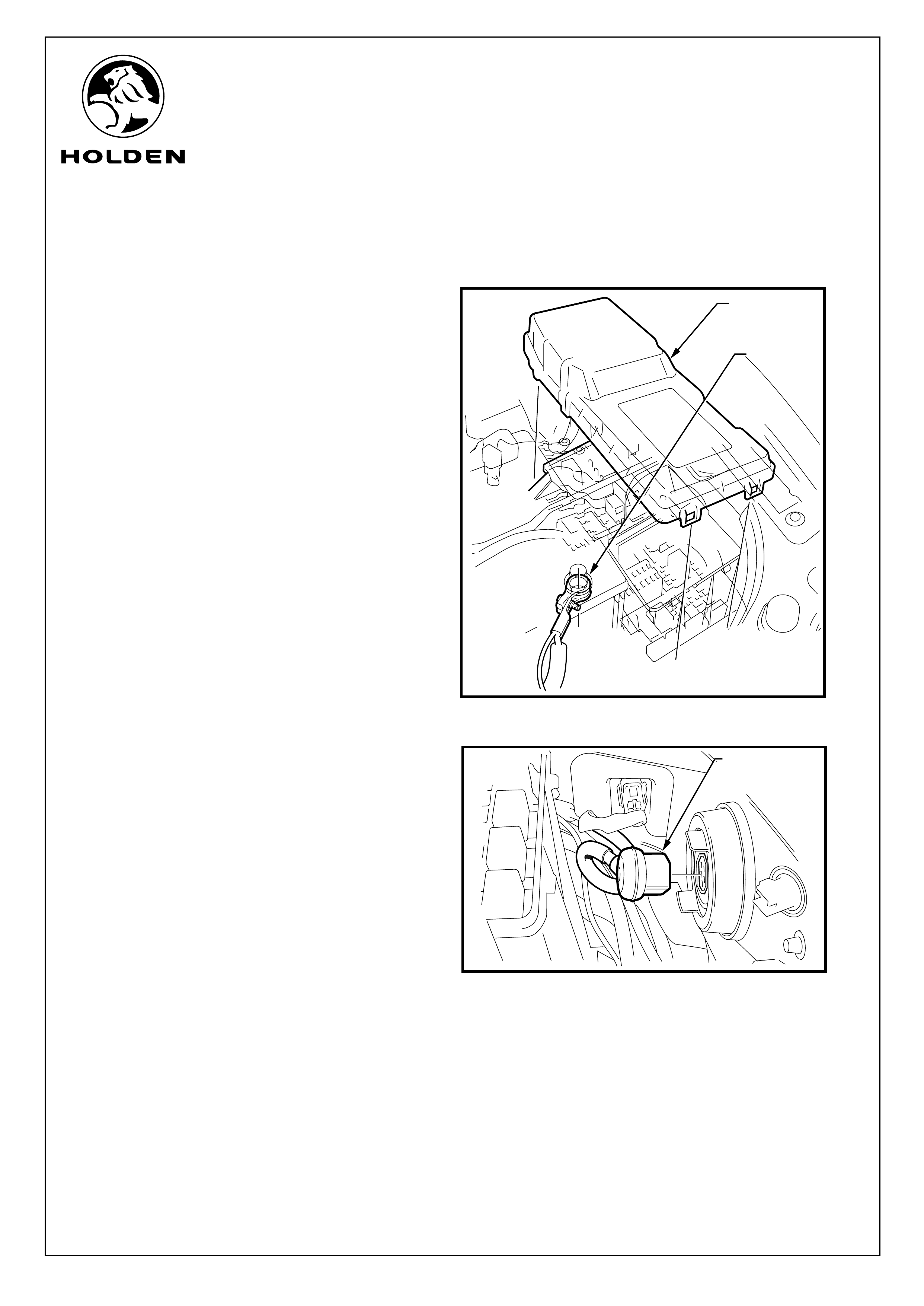
REMOVAL
1. Disconnect the negative battery lead.
Refer to Figure 1.
2. Remove the engine bay fuse/relay box cover
(clips - either end). Refer to Figure 1.
3. Unplug the left-hand side headlamp connector.
Refer to Figure 2.
FIGURE 1
FUSE/RELAY
COVER
NEGATIVE
BATTERY
LEAD
LEFT-HAND SIDE
HEADLAMP
CONNECTOR
FIGURE 2
COPYRIGHT
Reproduction in whole or part
prohibited without written approval
FD1275
19OCT04
HOLDEN LTD
Division of HOLDEN Ltd ACN 006 893 232
FITTING INSTRUCTIONS FOR
RA RODEO
DRIVING LAMP HARNESS
Page 3 of 12
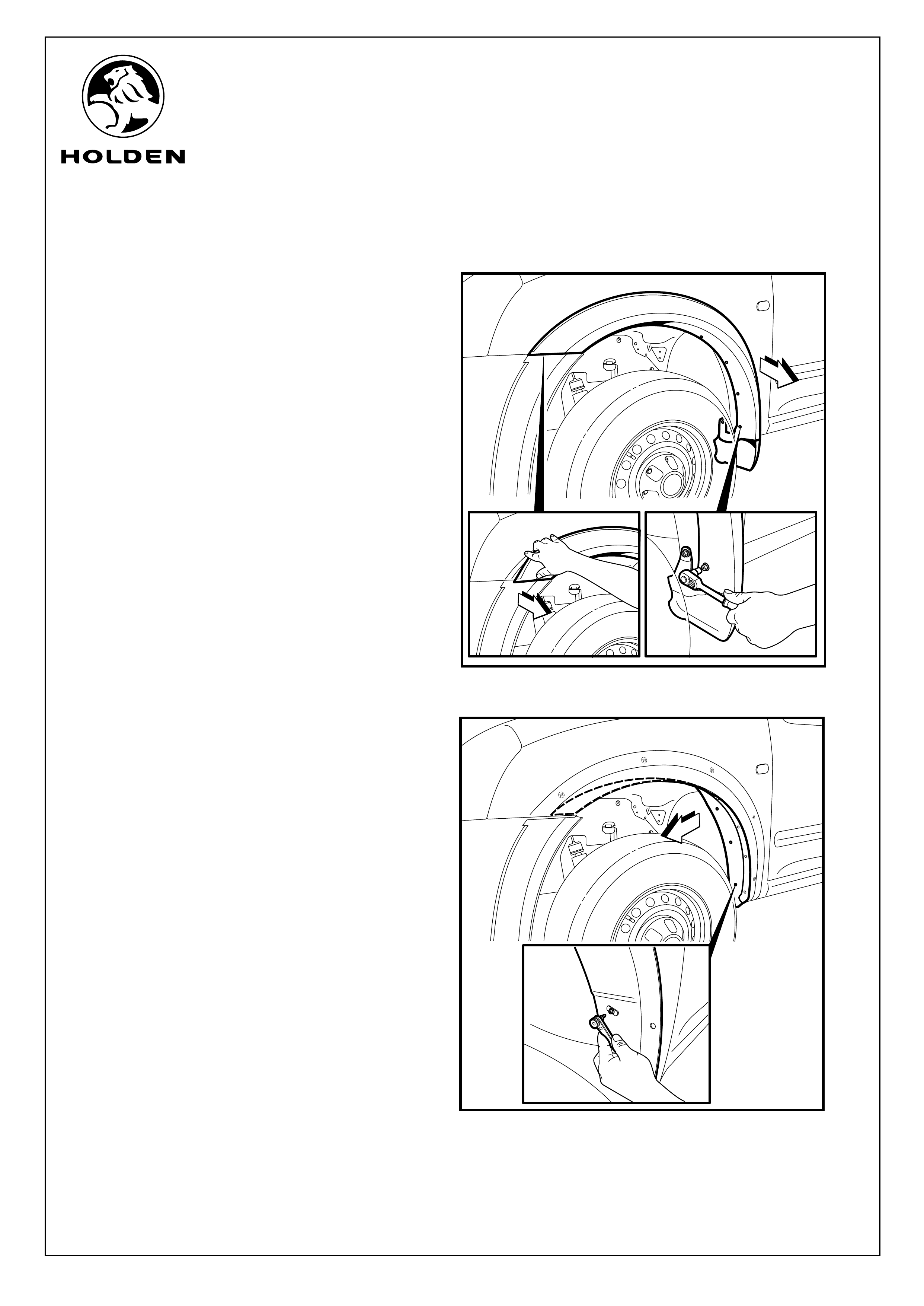
FITTING INSTRUCTIONS: continued...
4. Remove the 7 fasteners holding the front LHS
guard flare. Refer to Figure 3.
5. Remove front LHS guard flare from vehicle by
unclipping from guard. Refer to Figure 3.
6. Remove the 6 fasteners holding the LHS wheel
arch liner and then fold torwards the wheel.
Refer to Figure 4.
FIGURE 3
FIGURE 4
COPYRIGHT
Reproduction in whole or part
prohibited without written approval
FD1275
19OCT04
HOLDEN LTD
Division of HOLDEN Ltd ACN 006 893 232
FITTING INSTRUCTIONS FOR
RA RODEO
DRIVING LAMP HARNESS
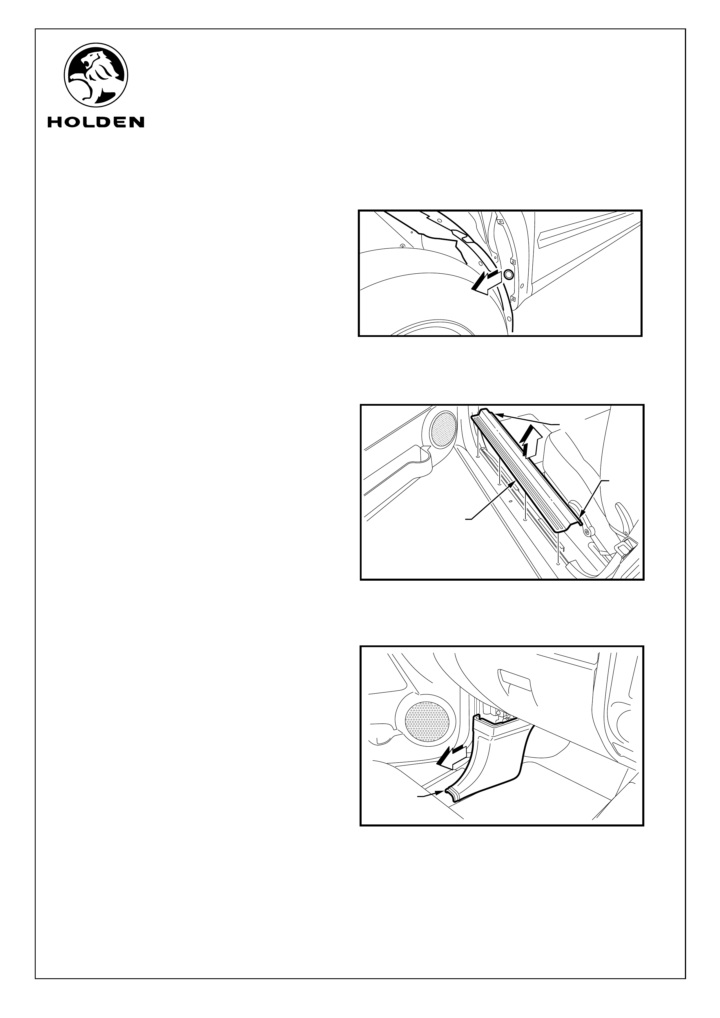
FIGURE 5
FITTING INSTRUCTIONS: continued...
7. Remove existing grommet on LHS front wheel
bulkhead. Refer to Figure 5.
8. Remove Front LHS passenger door sill trim
from vehicle. Refer Figure 6.Take care not to
damage retaining lugs(1) when removing. Refer
to Figure 6.
9. Remove Front LHS passenger side kick panel
from vehicle. Refer to Figure 7.
FIGURE 7
LEFT-HAND
SIDE KICK
PANEL
FIGURE 6
LEFT-HAND
SIDE DOOR
SILL TRIM PANEL
LUG (1)
LUG (1)
Page 4 of 12
COPYRIGHT
Reproduction in whole or part
prohibited without written approval
FD1275
19OCT04
HOLDEN LTD
Division of HOLDEN Ltd ACN 006 893 232
FITTING INSTRUCTIONS FOR
RA RODEO
DRIVING LAMP HARNESS
Page 5 of 12
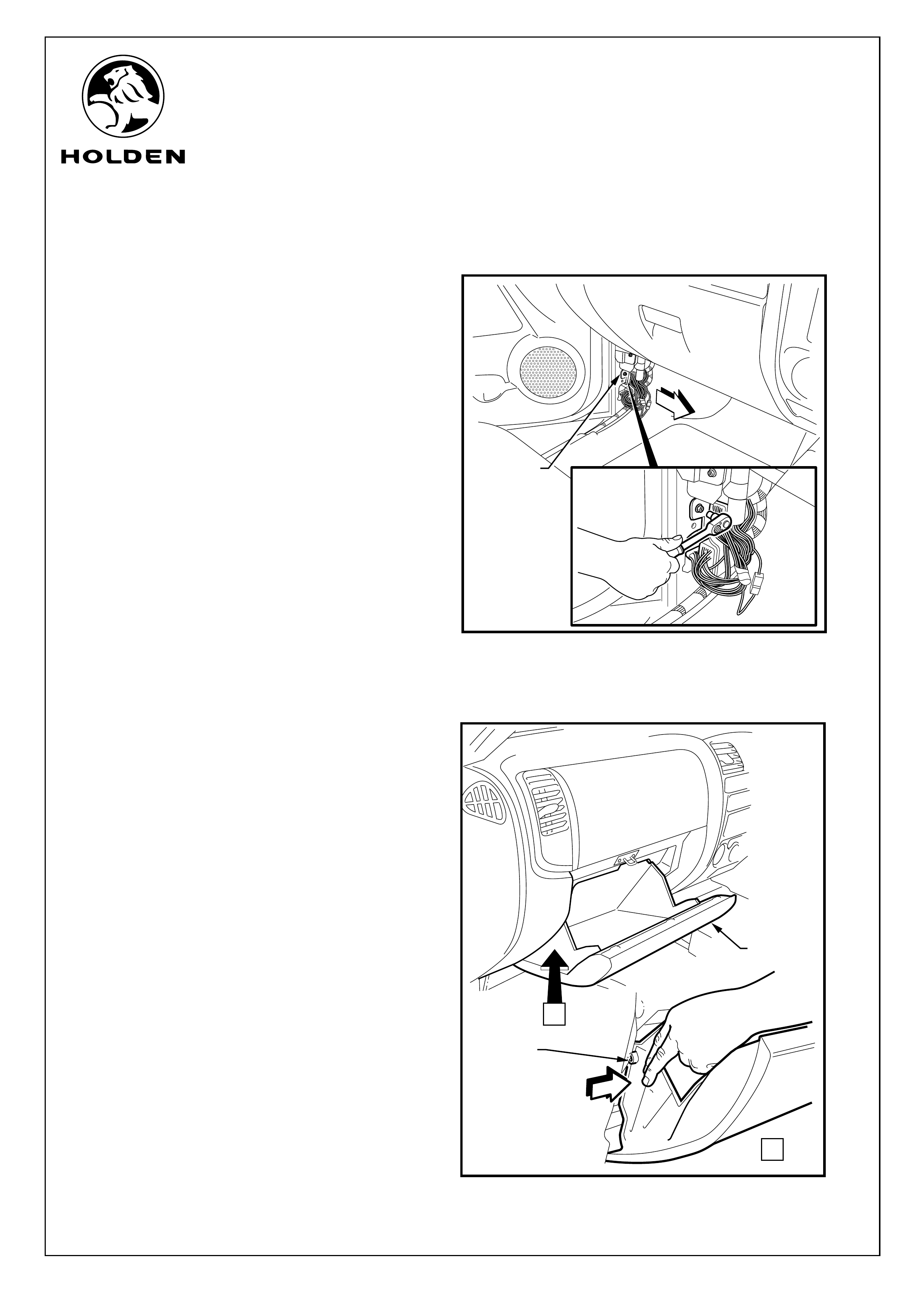
FITTING INSTRUCTIONS: continued...
10. Remove the fastener holding the connector
block and unclip connector block from vehicle.
Refer to Figure 8.
11. Unclip the glove box retainers and lower (but
do not remove) the glovebox. Refer to
Figure 9.
FIGURE 8
CONNECTOR
BLOCK
FIGURE 9
A
A
GLOVEBOX
RETAINING CLIPS
(LEFT & RIGHT
HAND SIDE)
GLOVEBOX
COPYRIGHT
Reproduction in whole or part
prohibited without written approval
FD1275
19OCT04
HOLDEN LTD
Division of HOLDEN Ltd ACN 006 893 232
FITTING INSTRUCTIONS FOR
RA RODEO
DRIVING LAMP HARNESS
Page 6 of 12
FITTING INSTRUCTIONS: - continued...
Refer to Figure 10 for the following:
12. Remove the switch blank on the right-hand
side dash panel (discard).
13. Remove the compartment insert on the right-
hand side dash panel below the switch location
(to ease switch and harness installation)
(retain).
14. Remove the fuse panel cover.
ENGINE BAY INSTALLATION
15. Pass the harness driving lamp connectors
through the opening in the left-hand side
radiator support panel and route behind the
grille and out at location of driving lamps. Cable
tie the harness to the grille to avoid fouling with
the condenser fan (if fitted). Refer to Figure 11.
FIGURE 10
SWITCH BLANK
FUSE PANEL
COVER
COMPARTMENT
INSERT
FIGURE 11
A
DRIVING
LAMP
HARNESS
DRIVING
LAMP
HARNESS
CABLE
TIE
RADIATOR
SUPPORT
PANEL
OPENING
COPYRIGHT
Reproduction in whole or part
prohibited without written approval
FD1275
19OCT04
HOLDEN LTD
Division of HOLDEN Ltd ACN 006 893 232
FITTING INSTRUCTIONS FOR
RA RODEO
DRIVING LAMP HARNESS
Page 7 of 12
FIGURE 12
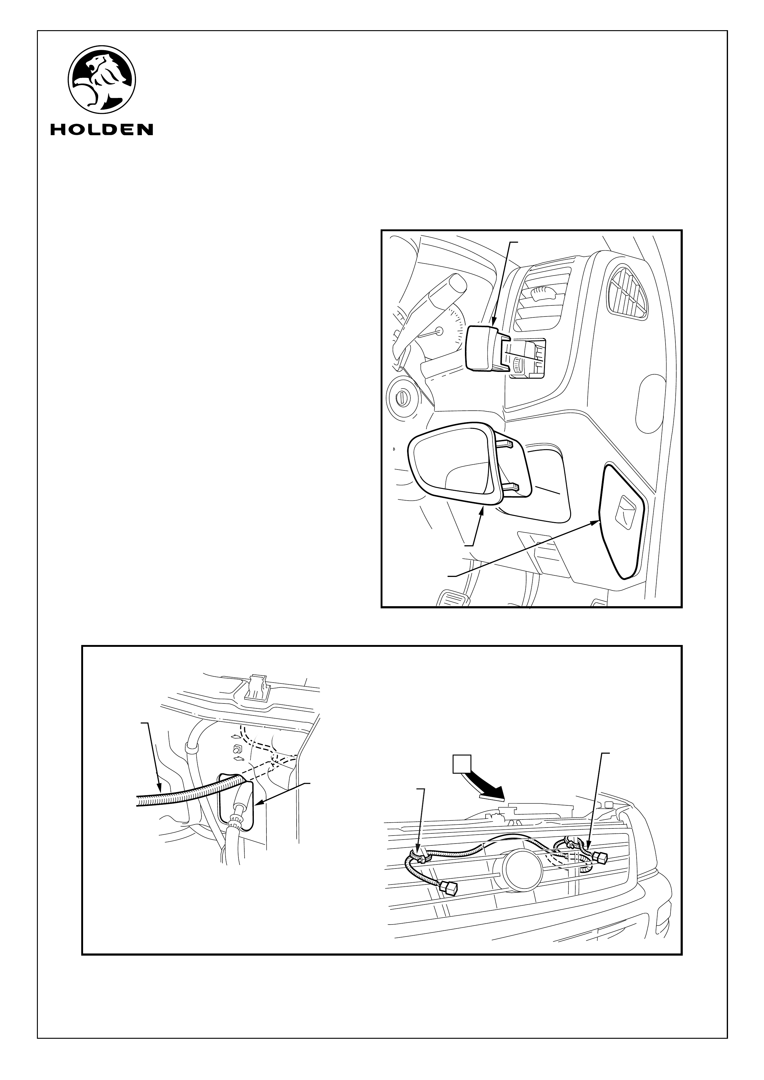
FITTING INSTRUCTIONS: continued...
16. Connect the driving lamp headlamp connector
to the left-hand side vehicle headlamp and the
existing headlamp connector to the
corresponding connector on the driving lamp
harness. Refer to Figure 12.
17. Seal the join between the existing headlamp
connector and the driving lamp harness
connector with insulation tape. Refer to
Figure 13.
DRIVING LAMP HARNESS
HEADLAMP CONNECTOR
EXISTING
HEADLAMP
CONNECTOR
DRIVING LAMP
HARNESS
CONNECTOR
FIGURE 13
SEAL JOIN
IN CONNECTORS
COPYRIGHT
Reproduction in whole or part
prohibited without written approval
FD1275
19OCT04
HOLDEN LTD
Division of HOLDEN Ltd ACN 006 893 232
FITTING INSTRUCTIONS FOR
RA RODEO
DRIVING LAMP HARNESS
POWER
CONNECTION
EARTH
CONNECTION
DRIVING LAMP
HARNESS
RELAY
DRIVING
LAMP
HARNESS
Page 8 of 12
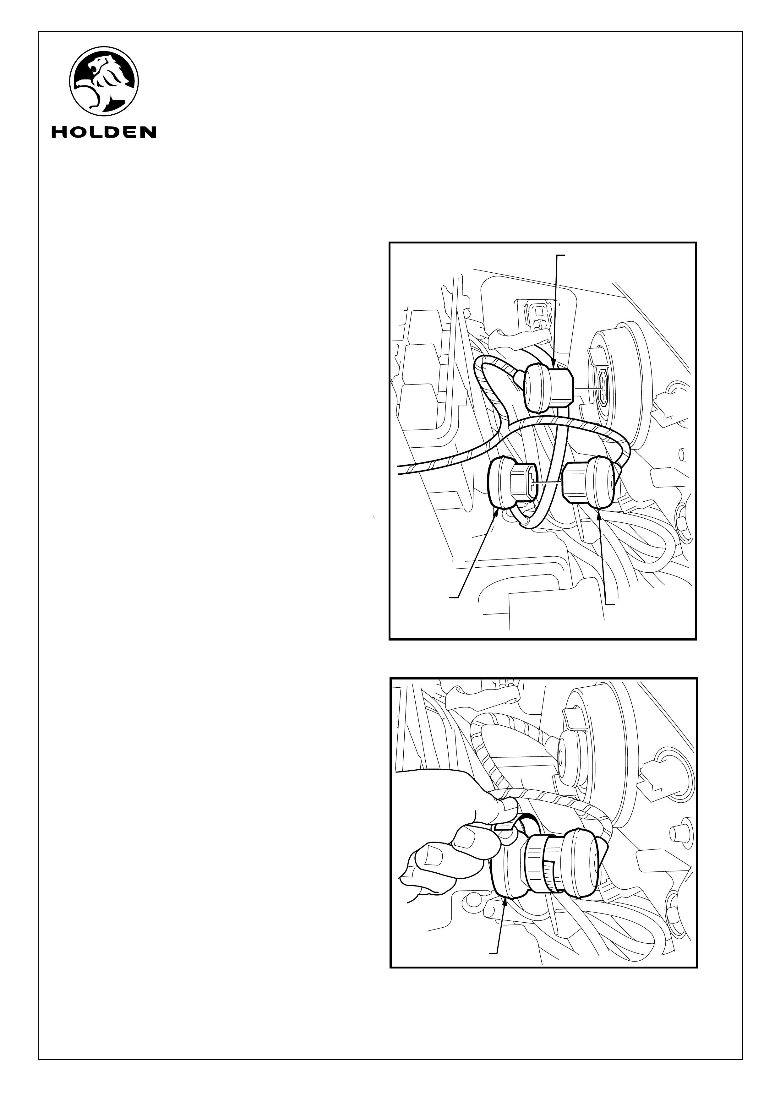
FITTING INSTRUCTIONS: continued...
18. Pass the driving lamp harness through existing
hole. Refer to Figure 14.
19. Passing the driving lamp harness through
existing hole. Refer to Figure 15.
FIGURE 14
ACCESS
HOLE
DRIVING
LAMP
HARNESS
DRIVING
LAMP
HARNESS
ACCESS
HOLE
FIGURE 15
COPYRIGHT
Reproduction in whole or part
prohibited without written approval
FD1275
19OCT04
HOLDEN LTD
Division of HOLDEN Ltd ACN 006 893 232
FITTING INSTRUCTIONS FOR
RA RODEO
DRIVING LAMP HARNESS
Page 9 of 12
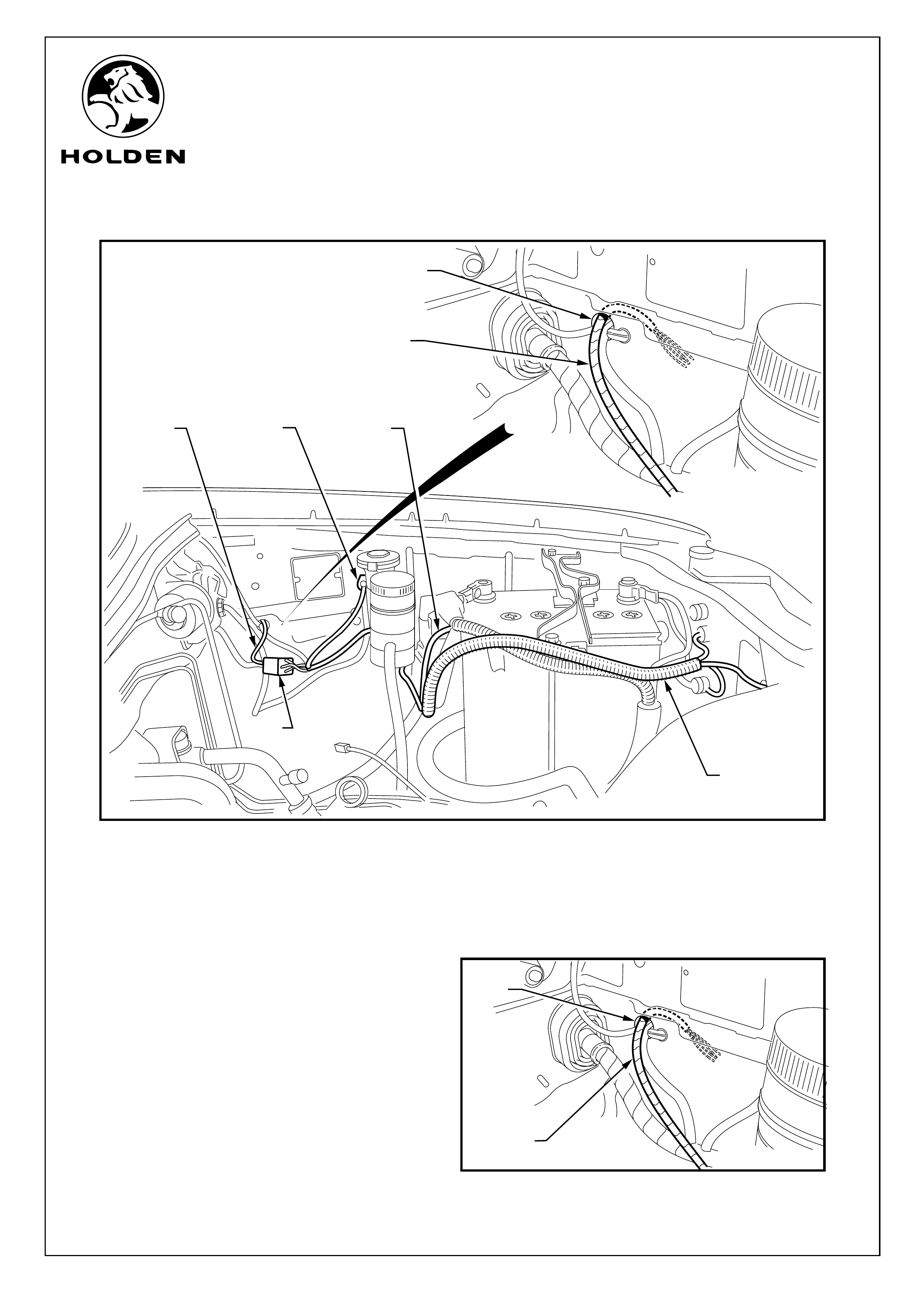
FITTING INSTRUCTIONS: continued...
20. Access the driving lamp harness from the front
LHS wheel arch and feed the driving lamp
harness through the hole in the LHS wheel
bulkhead, when the grommet is against the
bulkhead push grommet into the hole. Refer to
Figure 16.
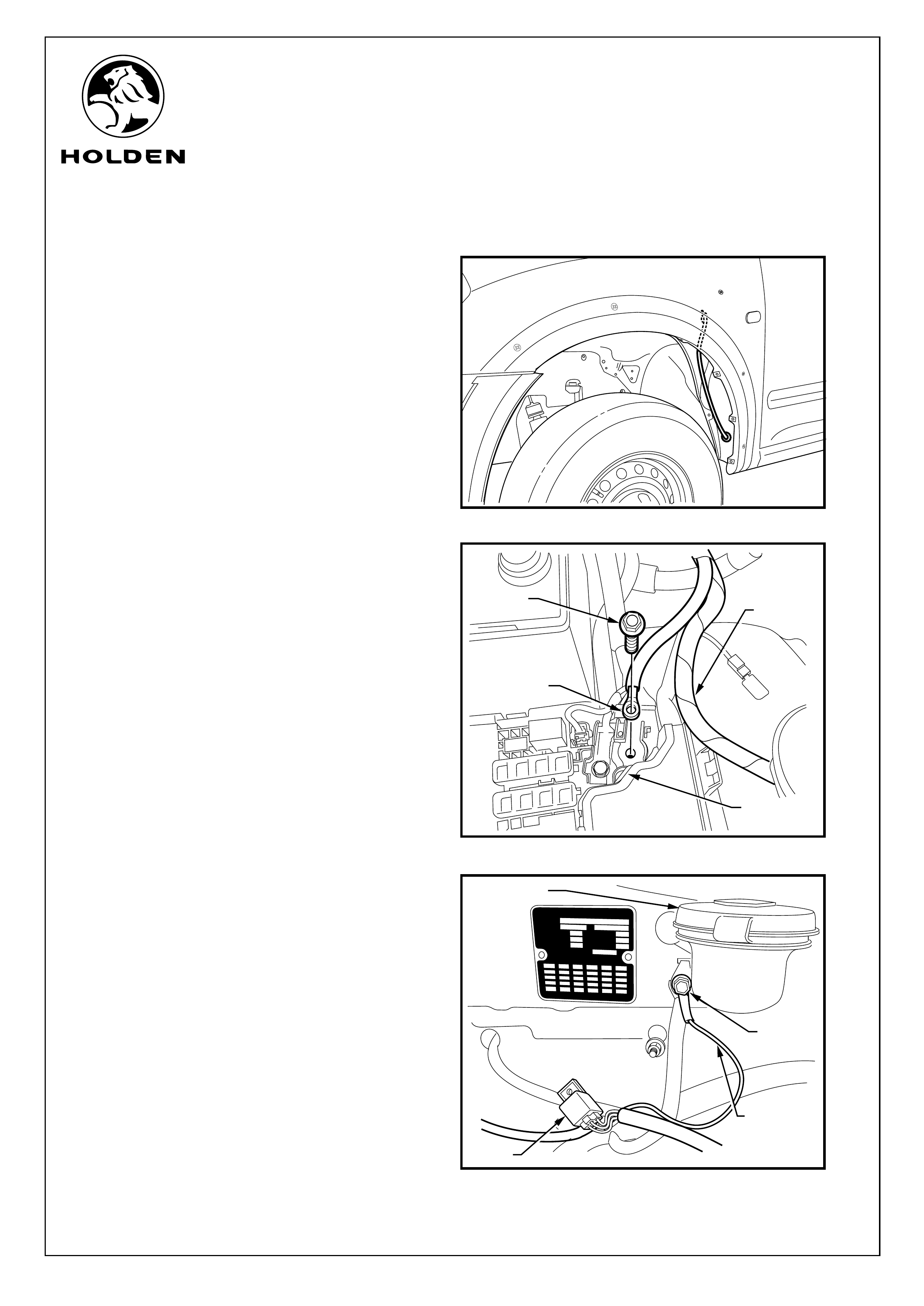
21. Using the existing fastener in the fuse/relay
box, fit the driving lamp harness power
connector. Refer to Figure 17.
22. Using the existing earth connection on the left-
hand side inner guard (beside the windscreen
washer filler), fit the driving lamp harness earth
lead. Refer to Figure 18.
FIGURE 16
FIGURE 17
FIGURE 18
DRIVING LAMP
HARNESS POWER
CONNECTOR
EXISTING
BOLT
DRIVING
LAMP
HARNESS
ENGINE BAY
FUSE PANEL
ISUZU MOTORS LTD.
ISUZU MOTORS LTD.
V.I.N.V.I.N.
M.D.M.D.
ENGINEENGINE
GRADEGRADE
BODY TYPEBODY TYPE
B. COLOUR/TRIM
B. COLOUR/TRIM
OPTIONOPTION
BUILD DATE
BUILD DATE
RELAY
DRIVING
LAMP
HARNESS
EARTH LEAD
EXISTING
BOLT
WINDSCREEN
WASHER
FILLER
COPYRIGHT
Reproduction in whole or part
prohibited without written approval
FD1275
19OCT04
HOLDEN LTD
Division of HOLDEN Ltd ACN 006 893 232
FITTING INSTRUCTIONS FOR
RA RODEO
DRIVING LAMP HARNESS
Page 10 of 12
FITTING INSTRUCTIONS: continued...
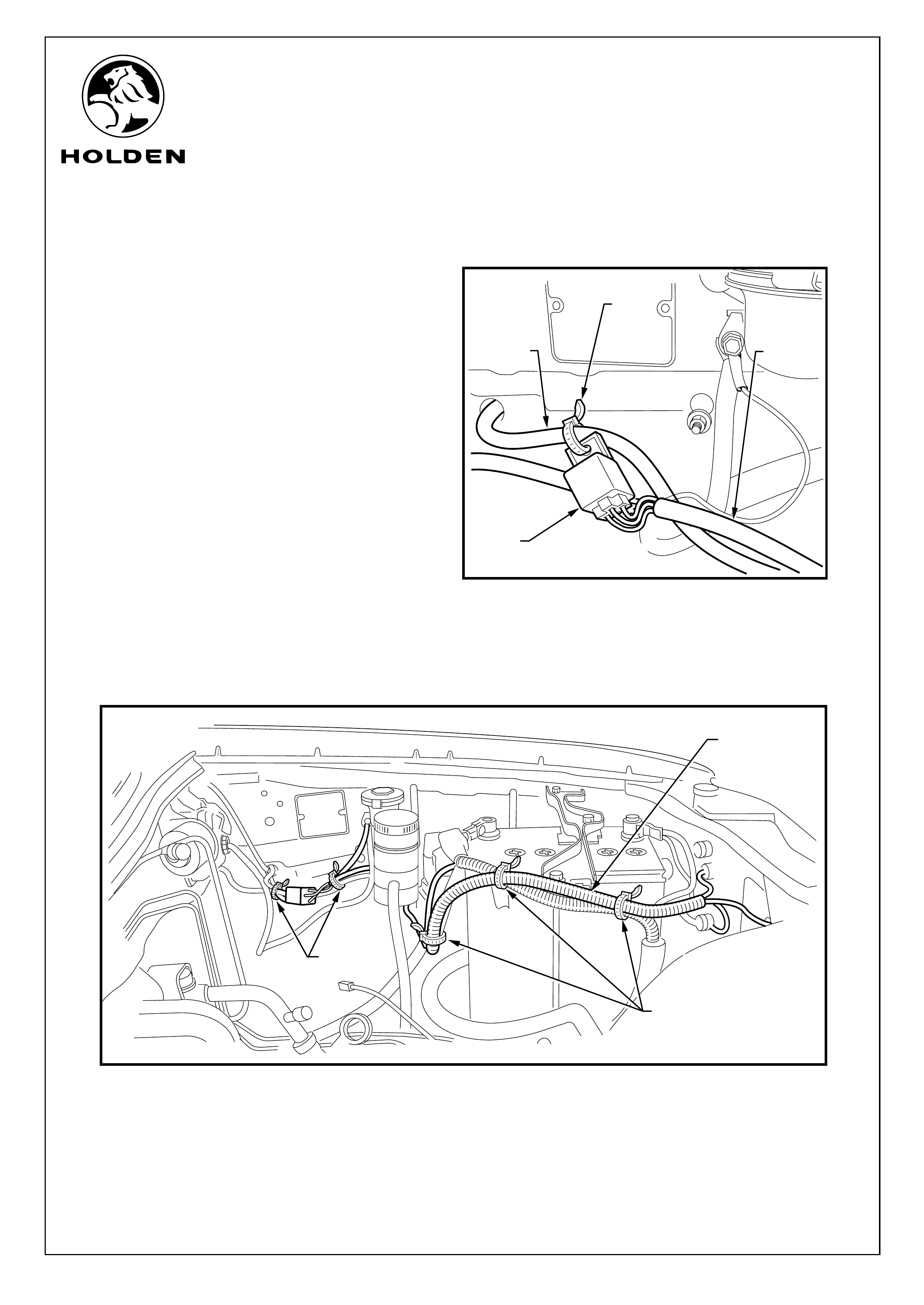
23. Secure the relay to the existing wiring harness
with a cable tie. Refer to Figure 19.
24. Cable tie the driving lamp harness to the
existing vehicle harness as shown.
Refer to Figure 20.
FIGURE 19
RELAY
CABLE
TIE
EXISTING
VEHICLE
HARNESS
DRIVING
LAMP
HARNESS
FIGURE 20
CABLE TIE
CABLE TIE
DRIVING LAMP
HARNESS
COPYRIGHT
Reproduction in whole or part
prohibited without written approval
FD1275
19OCT04
HOLDEN LTD
Division of HOLDEN Ltd ACN 006 893 232
FITTING INSTRUCTIONS FOR
RA RODEO
DRIVING LAMP HARNESS
Page 11 of 12
FIGURE 21
GROMMET
DRIVING
LAMP SWITCH
DRIVING
LAMP HARNESS
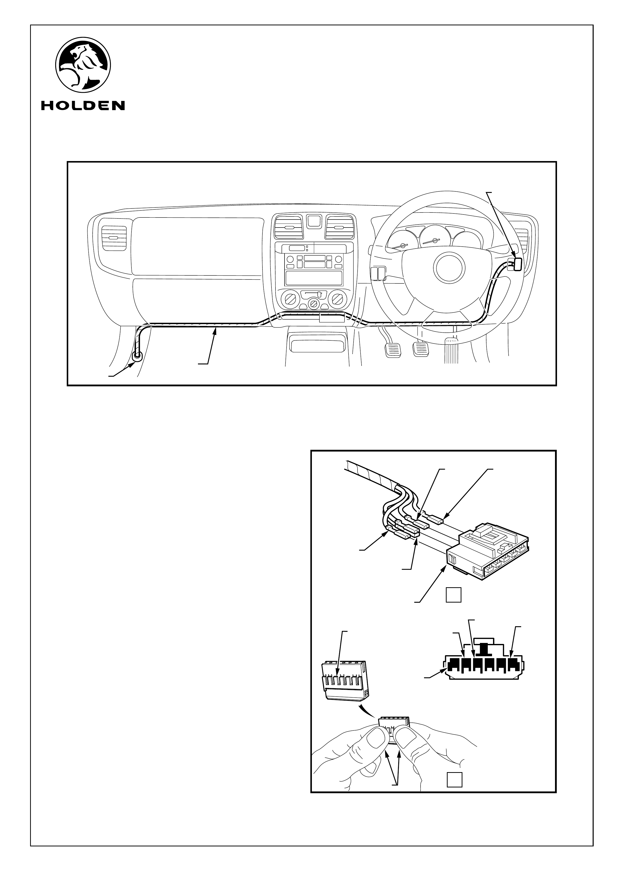
FITTING INSTRUCTIONS: continued...
INTERIOR INSTALLATION
25. Through the connector block opening, route
the interior harness between the blower
housing, evaporator housing (if fitted) and the
heater housing and the dash panel to the right-
hand side as indicated. Refer to Figure 21.
26. Fit the 1 BLACK,1 YELLOW and 2 GREEN
wires to the driving harness switch 6 Pin
connector as follows:-
1 YELLOW wire to Pin 5
1 BLACK wire to Pin 1
1 GREEN wire to Pin 6
1 GREEN wire to Pin 4
Secure the secondary lock (6 pin connector)
by pressing down on lock Refer to Figure 22,
View B
A
B
DRIVING LAMP
SWITCH HARNESS
6 PIN CONNECTOR
YELLOW
WIRE
GREEN
WIRE
BLACK
WIRE
GREEN
WIRE
FIGURE 22
SECONDARY
LOCK
PRESS
REAR VIEW
(6 PIN CONNECTOR)
BLACK
WIRE
GREEN
WIRE
6 5 4 3 2 1
11820
GREEN
WIRE
YELLOW
WIRE
COPYRIGHT
Reproduction in whole or part
prohibited without written approval
FD1275
19OCT04
HOLDEN LTD
Division of HOLDEN Ltd ACN 006 893 232
FITTING INSTRUCTIONS FOR
RA RODEO
DRIVING LAMP HARNESS
Page 12 of 12
FIGURE 23
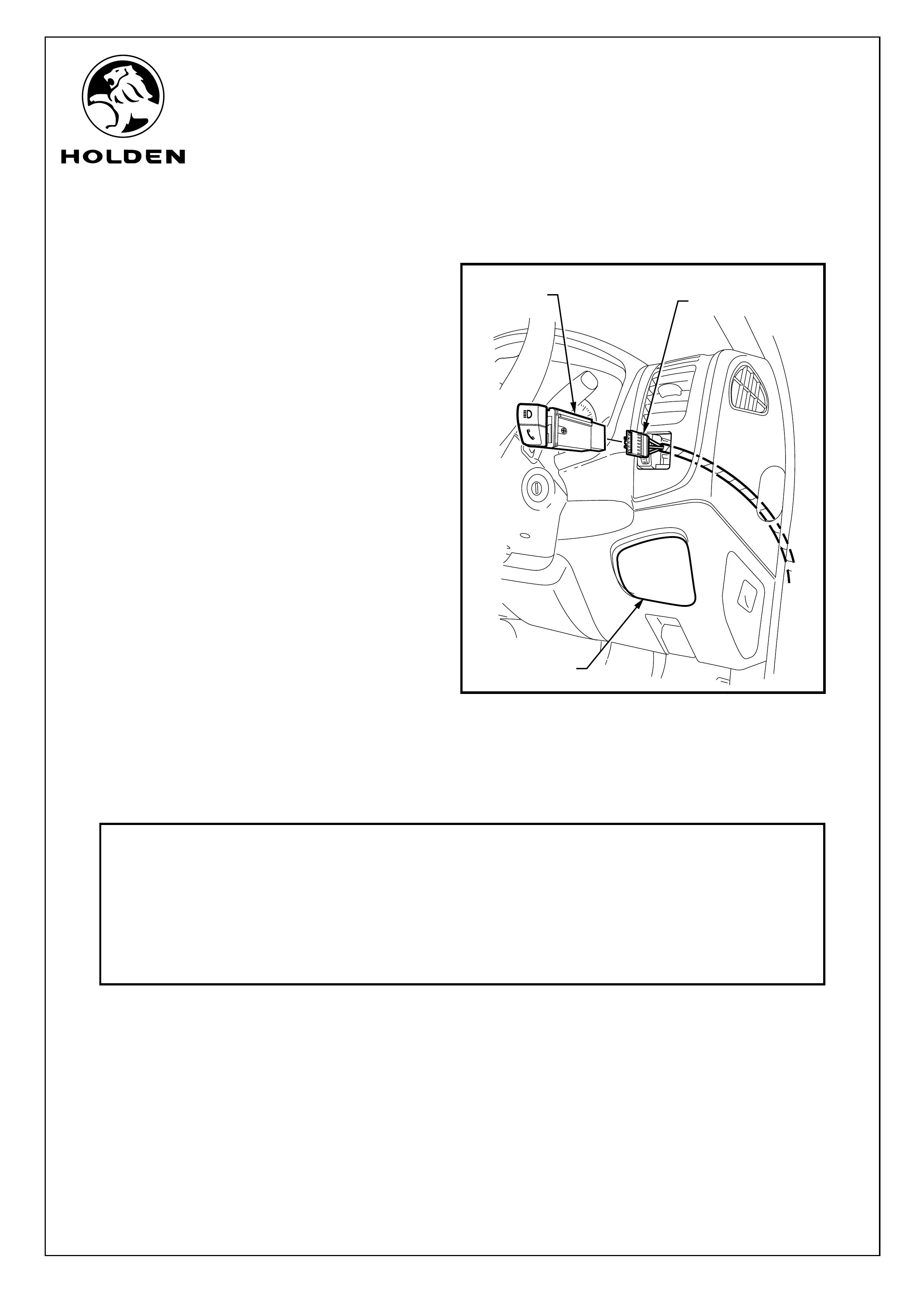
FITTING INSTRUCTIONS: continued...
Refer to Figure 23 for the following:
27. From beneath the dash, pass the driving lamp
harness up through the switch opening (using
the opening where the compartment tray was
removed to ease installation).
28. Connect the switch harness connector to the
driving lamp switch then push the switch in
until clicked into position.
29. Cable tie the interior driving lamp harness at
suitable locations to the existing vehicle
harness behind the dash panel to avoid fouling
of any components.
30. Connect the driving lamp harness to the driving
lamps and check for correct operation. With
switch depressed, driving lamps should
illuminate with high beam lamps.
31. Re-fit all removed components.
32. Place fitting instructions in the vehicle
glovebox.
CAUTION: Do not allow harness to foul with
the accelerator, clutch, brake pedal or steering
column.
CAUTION: Do not allow harness to foul with
the accelerator, clutch, brake pedal or steering
column.
DRIVING LAMP
SWITCH
CONNECTOR
DRIVING LAMP
SWITCH
COMPARTMENT
TRAY OPENING
PART NO. DESCRIPTION QUANTITY
92148795 DRIVING LAMP HARNESS 1
92148796 SWITCH 1
6-WAY CONNECTOR 1
CABLE TIES - 150mm 12
FD1275 DRIVING LAMP HARNESS FITTING INSTRUCTIONS 1
FD796 PROOF OF WARRANTY CARD 1
PARTS LIST
COPYRIGHT
Reproduction in whole or part
prohibited without written approval
FD1275
19OCT04
HOLDEN LTD
Division of HOLDEN Ltd ACN 006 893 232
FITTING INSTRUCTIONS FOR
RA RODEO
DRIVING LAMP HARNESS