
Air Conditioning Fitting Instructions
Kit No. 92148131 ISSUE DATE: JAN 2006
Instruction No: FD1381 Delphi No: 25187351
SERVICE PARTS OPERATIONS
RA RODEO - MYO6V6
3.6Lt DOHC V6 Petrol (4x2 & 4x4) Model Year 2006
RA RODEO - MYO6V6
3.6Lt DOHC V6 Petrol (4x2 & 4x4) Model Year 2006
R134aR134a

1.1 PREPARATION
1.2 POINTS TO CHECK
1.3 INSTALLATION PRECAUTIONS
1.4 TORQUE CHART
1.5 LABELS
1.6 PARTS
1.7 SPECIAL TOOLS
2.0 SPECIFICATIONS
3.0 TIGHTENING TORQUES
4.0 EVAPORATOR ASM FITMENT
4.1 PARTS TO BE REMOVED
4.2 EVAPORATOR INSTALLATION
5.0 CONDENSER FITMENT
6.0 RUBBER SEALS
7.0 LIQUID LINE FITMENT
8.0 COMPRESSOR / MOUNTING BRACKET FITMENT
9.0 SUCTION LINE
10.0 DISCHARGE LINE FITMENT
11.0 DRIVE BELT INSTALLATION
12.0 DRAIN HOSE INSTALLATION
13.0 A/C RELAY LOCATION
14.0 EVACUATION AND CHARGING PROCEDURE
15.0 ELECTRICAL
16.0 FAULT SOLUTIONS
INSTALLATION CHECKLIST
2
2
2
2
2
3
3
3
3
4
4
5
6
8
9
9
10
10
11
11
12
13
15
15
16
1
CONTENTSCONTENTS
2
PREPARATIONPREPARATION
PREPARATION
Read through these fitting
instructions prior to beginning the
installation. Then carefully follow
these instructions throughout
installation from Step 1.0 to
charging and testing the system.
POINTS TO CHECK
a) Open and inspect kit for any damage to
parts.
b) Check all parts are present in the kit using
the contents list supplied.
c) Check the vehicle for any damage to the
interior and exterior.
d) Check function of Ventilation Blower Fan,
Temperature Control Door, Horn, Light,
Headlamps.
INSTALLATION PRECAUTIONS
a) This system has been designed to suit
standard wiring by the vehicle manu-
facturer, the wiring of non-approved
accessories could result in malfunction of
the unit or damage to the vehicle.
b) Disconnect neg. lead from the battery.
c) Route all refridgerant hoses, tubes and
wiring harnesses to avoid fouling.
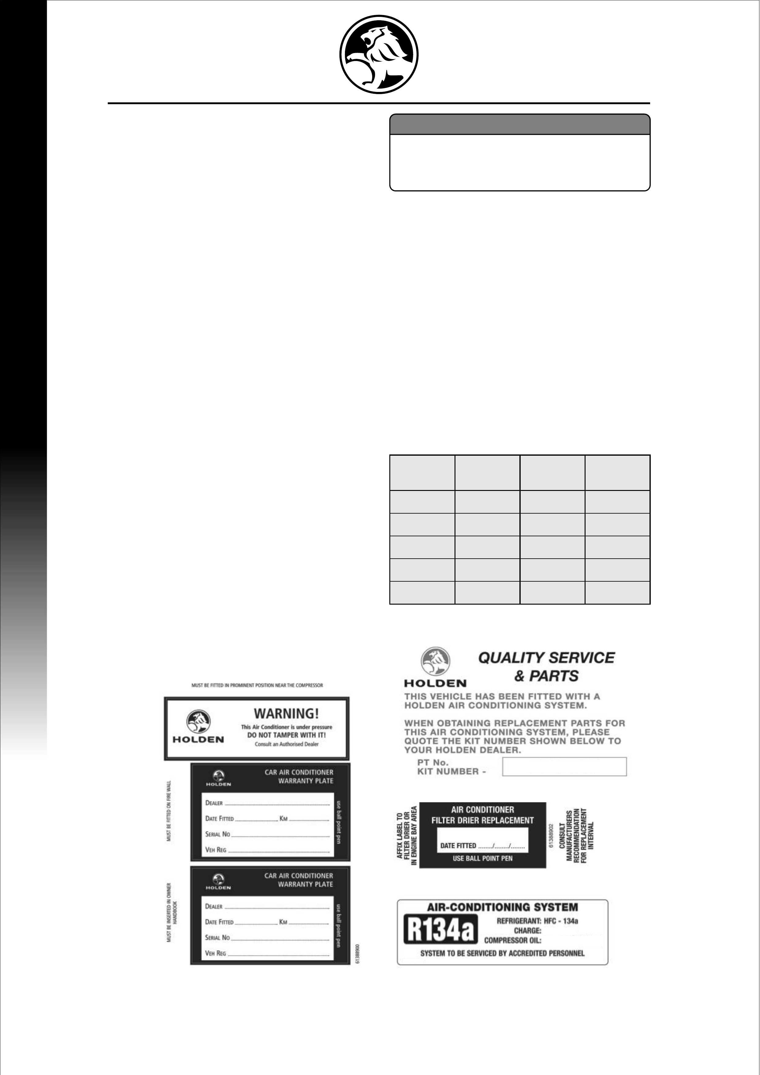
LABELS
d) To prevent entry of foreign moisture into
the system do not remove shipping plates
or plugs until immediately before
installation of the components.
e) O-Rings do not require lubrication as they
are pre-fitted to most tubes/hoses and
pre-lubricated with silicon at the
manufacturer.
f) Use two spanners when tightening
fittings.
g) Use torques as specified.
h) Use only specific R134a charging
equipment and leak detector.
1.4 TORQUE CHART
HOSE & TUBE FITTINGS
NOTE:
This system uses a specific lubricating
oil - Polyalklene Glycol (PAG). This oil
is highly hygroscopic, adhere to step D
1.1
1.2
1.3
SIZE
No.5
No.6
No.8
No.10
No.12
5/16
3/8
1/2
5/8
3/4
9/16-18
5/8-18
3/4-16
7/8-14
1-1/6-12
13.0-15.0
11.0-16.0
18.0-23-0
24.0-30.0
30.0-38.0
TUBE
O.D THREAD
-UNF TORQUE
Nm
1.5
92148131
25187352
25187353
+
-
700 25g700 25g
PAG 1 (230ml)PAG 1 (230ml)
PART S
Retain all parts removed in procedure for refitment later unless instructed to dispose.
SPECIAL TOOLS REQUIRED FOR INSTALLATIONS
Torque Wrench. (up to 250Nm Capacity)
SPECIFICATIONS
TIGHTENING TORQUES
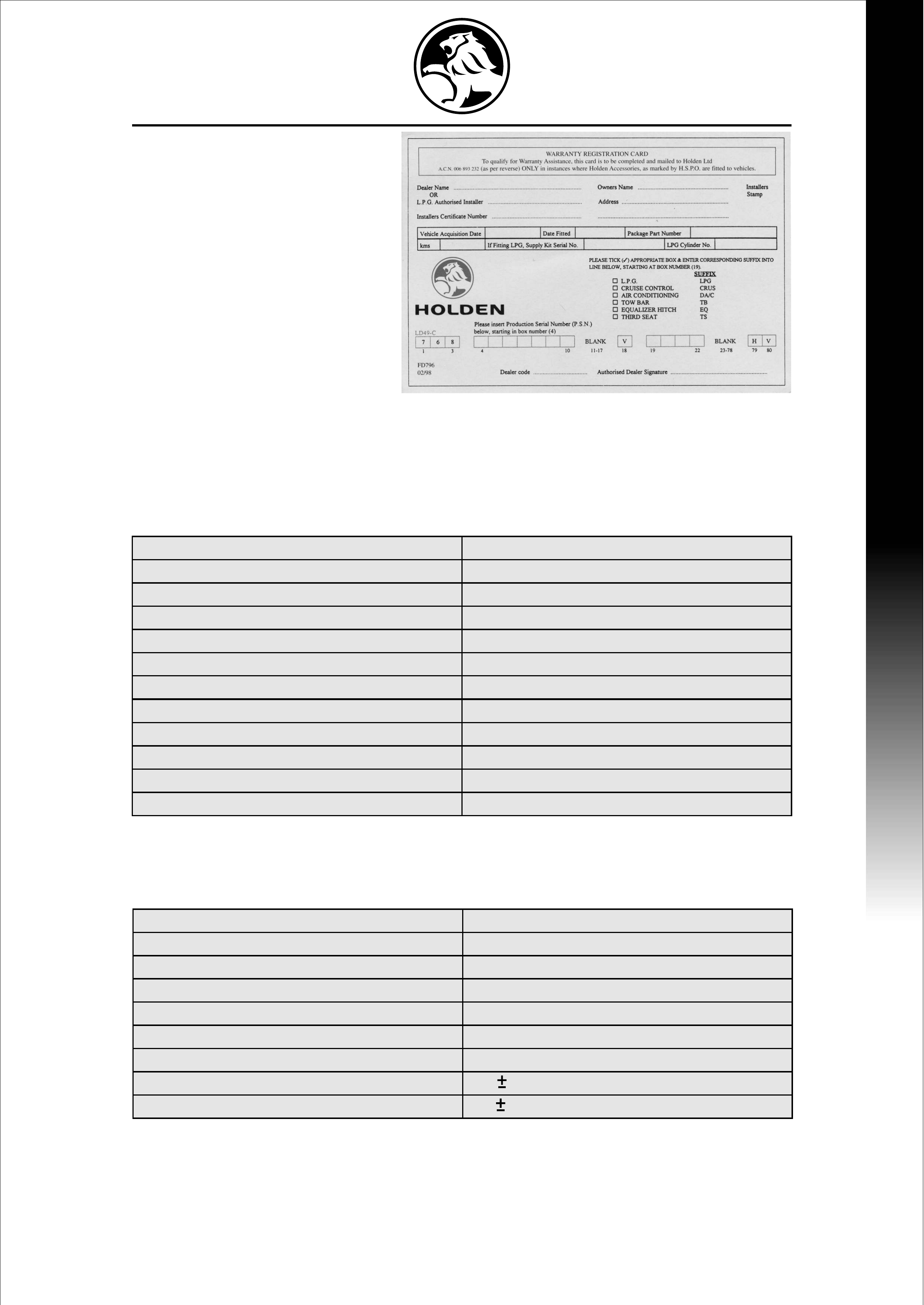
WARRANTY CARD
Condenser - Discharge Pipe 7-10Nm
Compressor - Discharge Pipe 20-30Nm
Compressor - Suction Line 20-30Nm
Suction & Liquid Line Fitting - TXV 24-30Nm
Liquid Line Join 7-10Nm
Liquid Line - FDR 13-15Nm
Compressor Mounting Bolts 30-40Nm
Compressor Bracket to Engine - M10 58 9Nm
- M8 22 3Nm
1.6
1.7
2.0
3.0
Compressor V6 Petrol Delphi SP15
Clutch 12 Volt 6-Poly V
Condenser 3 pass
(incorporates Pressure Transducer & Filter Receiver Drier)
High Pressure
Pressure Transducer -
Low Pressure
-
A/C OFF 3000kpa A/C ON 2400kpa
A/C OFF 173kpa A/C ON 235kpa
Evaporator Assembly Plate Type
(incorporating TXV and Thermistor)
Refrigerant Capacity R134a 700 +/- 25 grams
Lubricating Oil RL10004 (PAG 1)
Compressor Oil 230cc
'O' ring Material HNBR
3
TIGHTENING TORQUES & SPECIFICATIONSTIGHTENING TORQUES & SPECIFICATIONS
EVAPORATOR ASSEMBLY FITMENT
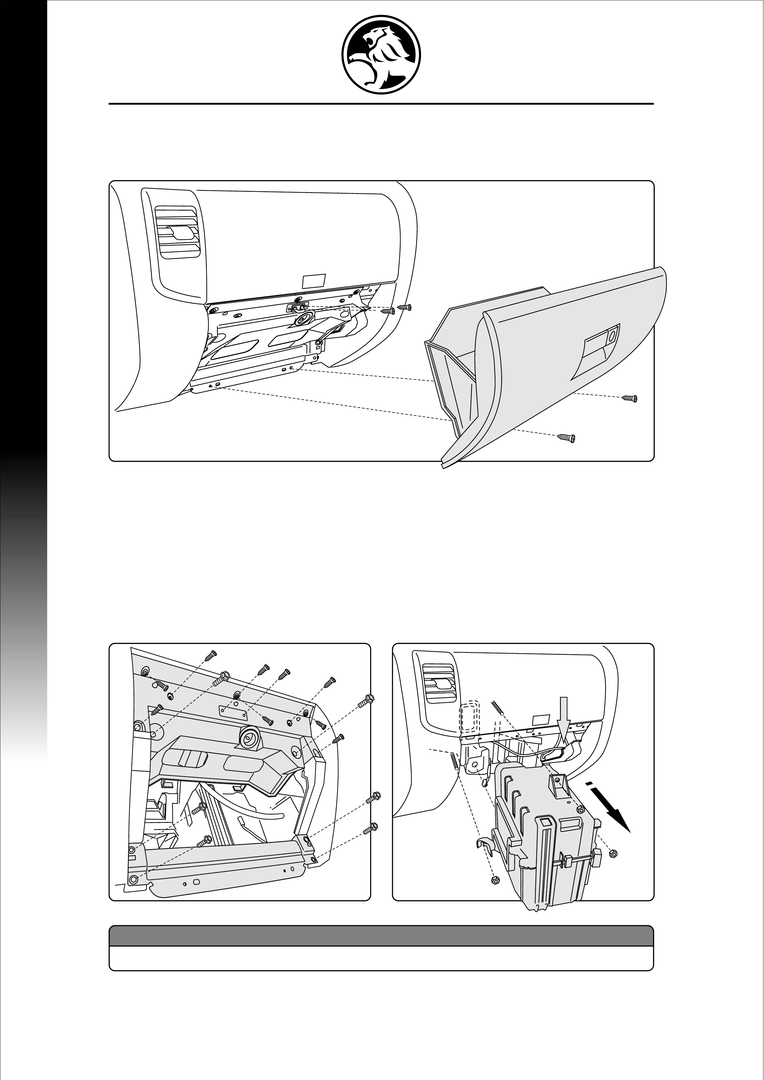
PARTS TO BE REMOVED
a) Remove Glove Box. (2 screws - 15mm)
b) Remove Glove Box Latch. (2 screws - 15mm)
c) Remove Glove Box Lower Panel. (4 x 15mm 'M6x20' bolts)
d) Remove Glove Box Upper Panel by pushing the panel out from behind and pulling
downwards at the same time. (7 screws - 15mm & 2 'M6x20' bolts).
e) Lower the Glove Box Upper slightly and disconnect Light Connector - where fitted.
(white under black foam insulation)
f) Disconnect Air-mix door cable (take note of cable position in
retainer) from Air-mix Door and place clear of current air box.
g) Remove existing Air Box (3 M6 nuts) for Evaporator installation as per procedure 4.2
Disconnect Air-Mix
Cable Here
(a)&(b)
(c)to(e)
(f)&(g)
4.0
4.1
EVAPORATOR ASSEMBLY FITMENTEVAPORATOR ASSEMBLY FITMENT
4
NOTE:
Do not forget to reconnect Air Mix Cable before installing glovebox
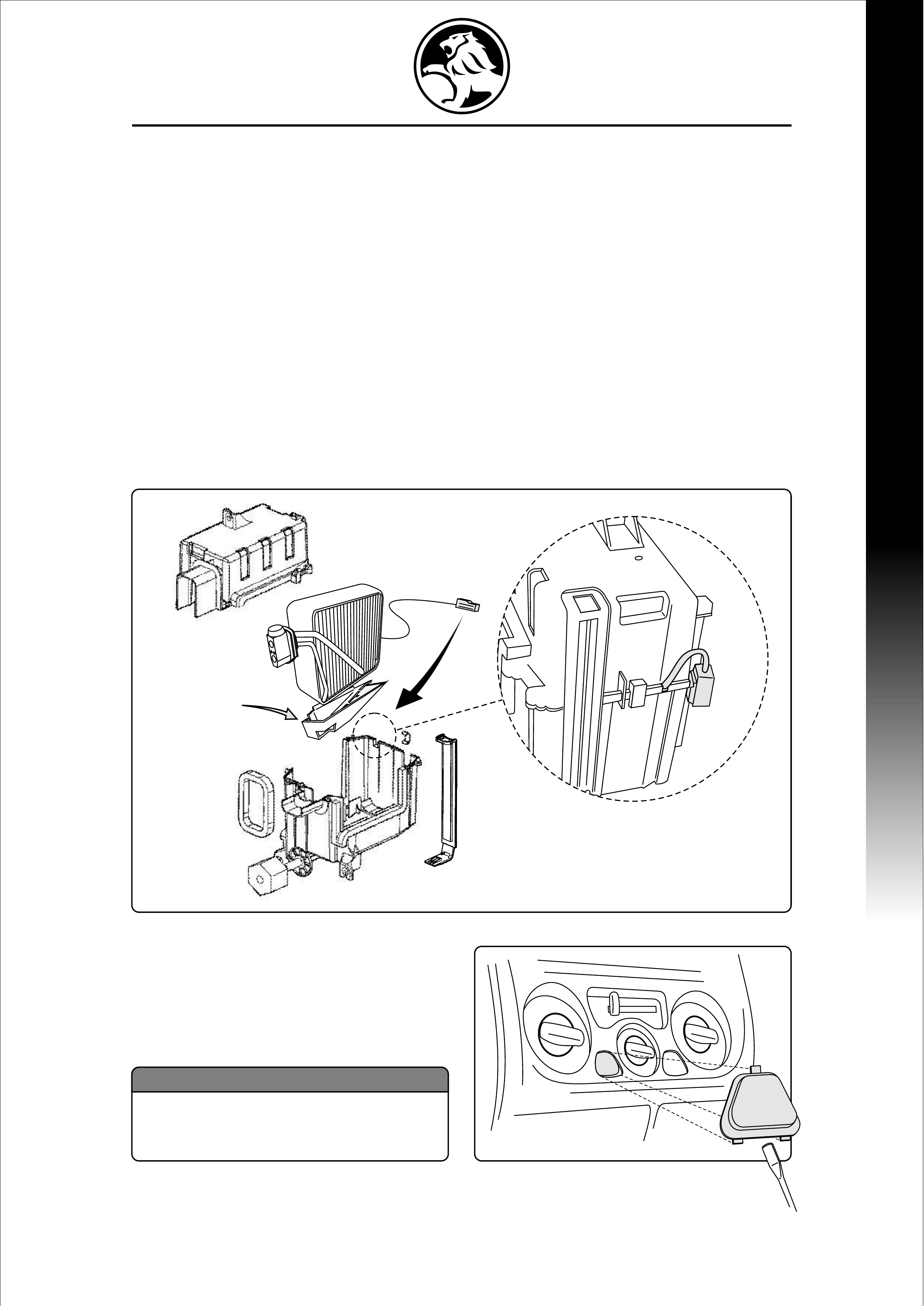
EVAPORATOR INSTALLATION
a) Slice foam seals on both sides of Evaporator case at joint. Split Air-box/Evaporator case in
half (remove 5 screws, 1 spring clip, access panel). CAREFUL NOT TO DAMAGE SEALS
b) Install white styrene Evaporator Liner supplied into lower half of case.
c) Install Evaporator Core into lower half of evaporator case, then install top half of evaporator
case (WARNING - route Thermister wiring through small recess in Evaporator case at the
joint line) mount Thermister to Evaporator case. Refit 5 screws and 1 spring clip.
d) Fit drain hose supplied & install seals at drain hose & TXV outlet of Evaporator case.
e) Install Air-box/Evaporator ASM. (Take note of holes in Firewall for TXV & Drain Plug).
Locate Thermister Cable (Brown Connector) in wiring harness above Evaporator ASM
cavity. Release Connector from Main harness and hold clear when installing evaporator
ASM.
f) Fasten Evaporator Assembly in place. (3 M6 nuts)
g) Reconnect Air-mix door cable. Ensure sheath is refitted in identical
position (refer cable position as prior to removal). Check full
operation of air mix cable and control head dial. (Dial should rotate
to full Hot & full Cold positions)
h) Plug in Vehicle Thermister Harness to
Thermister on Evaportator Assembly.
- Refer to (f)
i) Reverse section 4.1 to reinstall Glove Box
assembly.
j) Remove A/C Button Blanking Cover using
a small FLAT BLADE screw driver.
4.2
5
EVAPORATOR ASSEMBLY FITMENTEVAPORATOR ASSEMBLY FITMENT
NOTE:
To Avoid Dash panel damage place
masking tape on dash before removing
A/C button blanking cover.
(j)
A/C
(b) Lower Case
Liner
Thermister Plug Location
Passenger Compartment Side of Evaporator Asm
CONDENSER FITMENTCONDENSER FITMENT
6
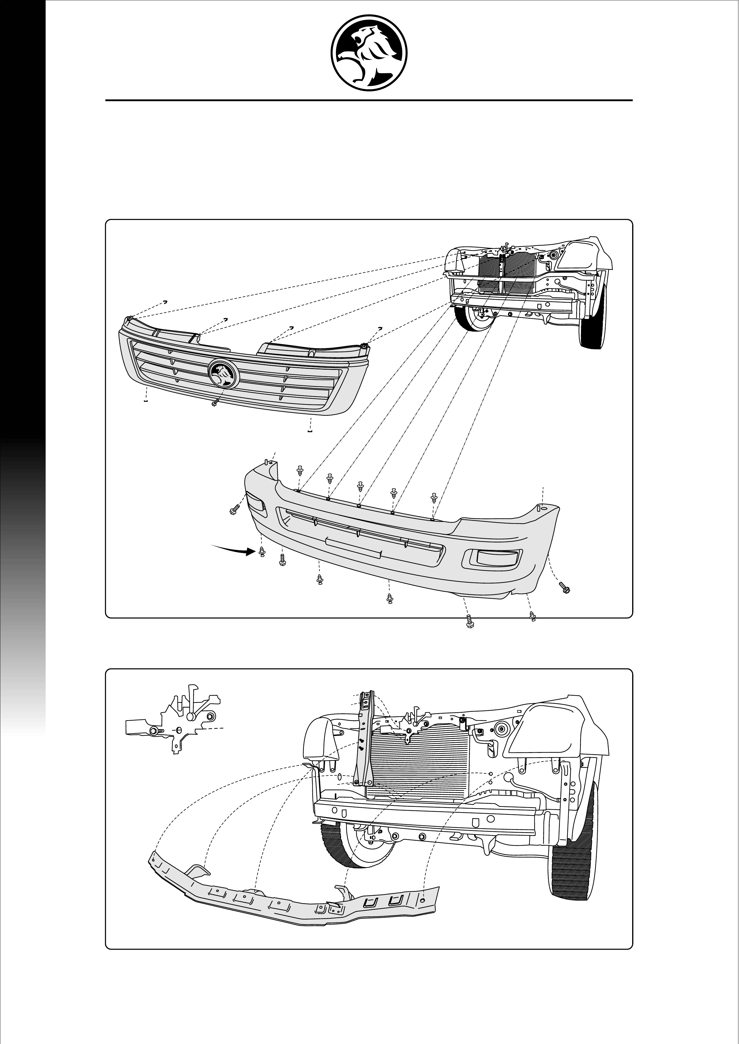
CONDENSER FITMENT
a) Remove Grille. (4 clips at top. 2 clips at bottom rear and 1 screw at centre of grille)
Take care not to drop clips into upper cross member.
b) Remove Bumper Facia: 9 Scrivets at top and bottom, 1 bolt in each wheel arch, 2 bolts on
outside under section of bumper.
NB: TAKE CARE WHEN REMOVING SCRIVETS AND SCREWS. FOR FURTHER
INFORMATION REFER TO YOUR HOLDEN SERVICE MANUAL.
c) Remove Bonnet Lock Support Bar. (4 M6 bolts)
d) Remove Bumper Support Cross Member. (2 M6 bolts & 6 M6 nuts)
5.0
Do not remove
Bonnet Lock
xx
(c)&(d)
GRILLE: 6 Clips & 1 screw
(top - 4, bottom - 2, screw in centre)
BUMPER: 9 scrivets
2 bolts in wheel Arch
2 Bolts on bottom
(a)&(b)
SCRIVETS
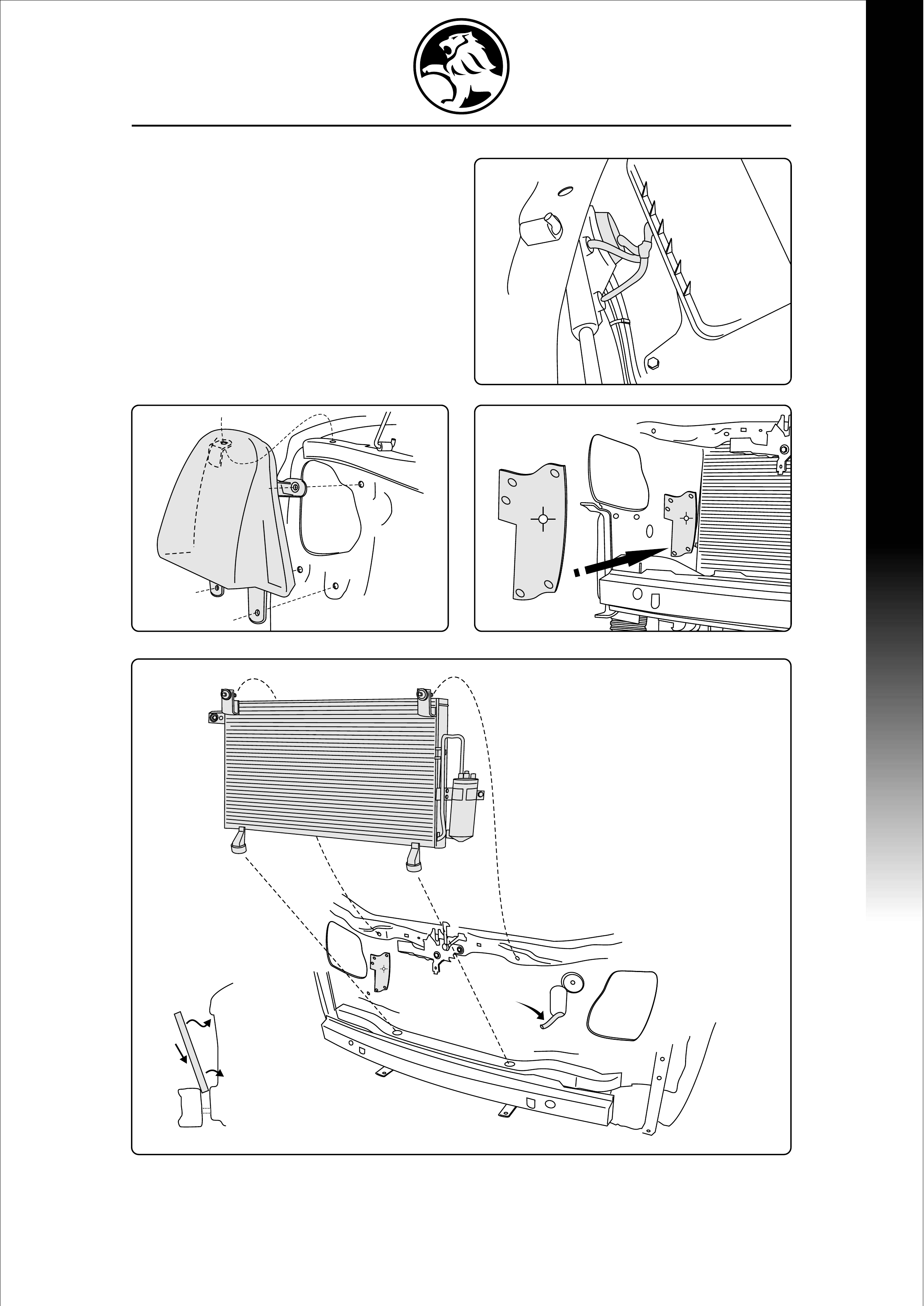
e) Unplug Headlights. (3 connectors)
f) Remove both Headlights.
g) Fit Liquid Line Rubber Seal.
h) Fit condenser (2 M6 25mm Bolts bolts
incorporated in Upper Mounts)
i) Locate & Connect Pressure Transducer
Harness behind Left Hand Headlight Asm.
7
1
2
3
1) Place rubber feet of
condenser between
bumper intrusion &
body.
2) Rock the top of the
condenser backwards
and up into place.
3) Lift and place rubber
feet into holes.
CONDENSER FITMENTCONDENSER FITMENT
(e)
(g)(f)
(h)
(i)
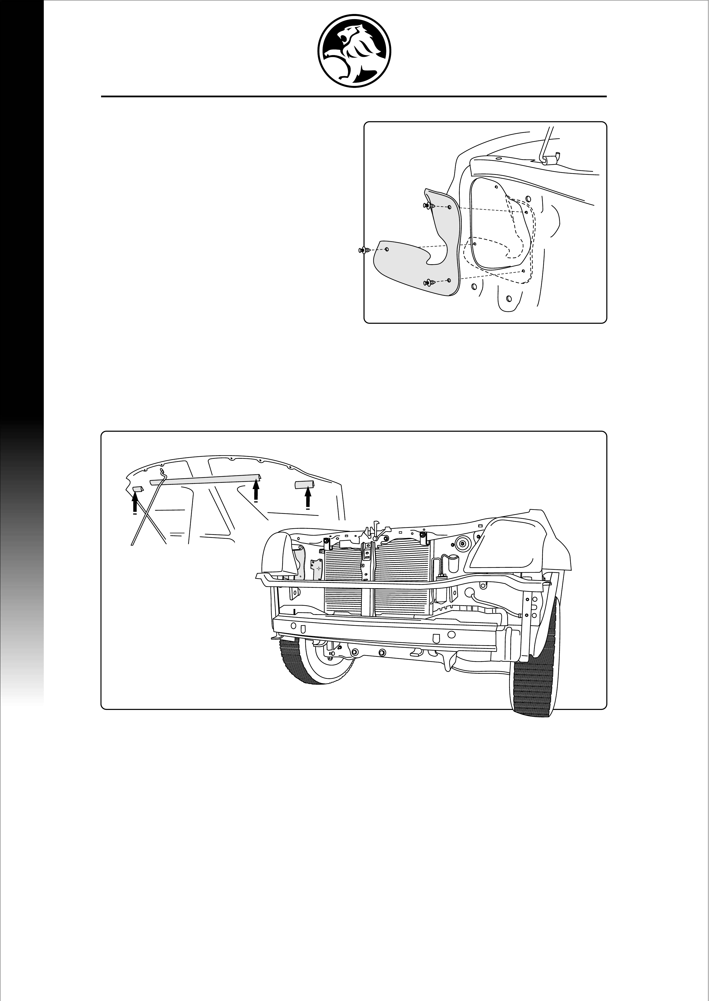
6.0 RUBBER SEAL INSTALLATION
a) Fit Headlight Seals.
(1 seal in each headlight cavity using 3
Scrivets in each seal)
b) Fit Bonnet Seals to holes provided, in the
leading edge of bonnet. (1 large, 2 small)
RUBBER SEAL INSTALLATIONRUBBER SEAL INSTALLATION
8
(a)
Bonnet Seals
(b)
In holes provided
N.B: View diagram for correct Bonnet Seal fitment (b).
9
LIQUID LINELIQUID LINE
(a)
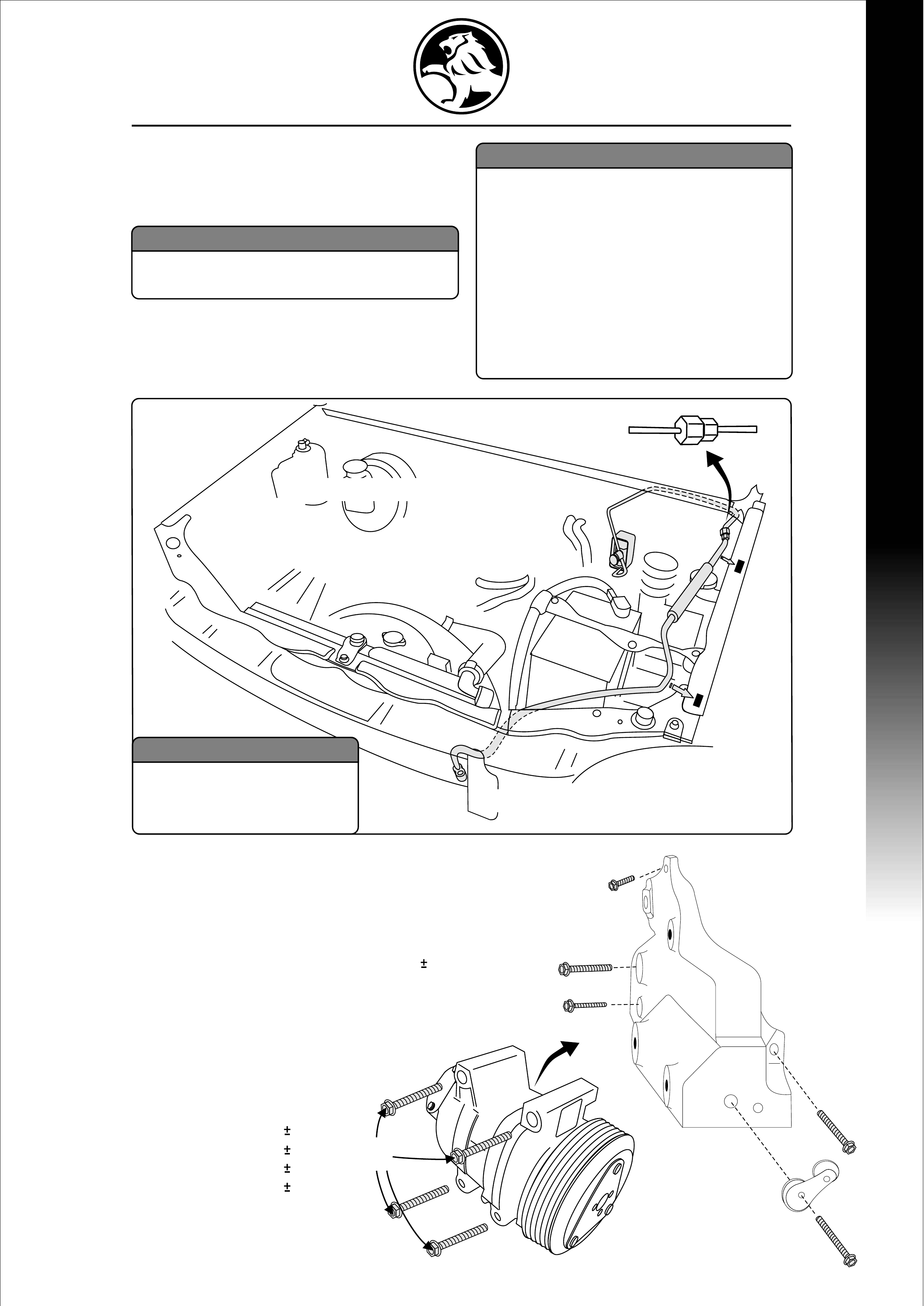
LIQUID LINE FITMENT
a) Install Liquid Pipe to Receiver Drier
through Radiator Support Panel, DO NOT
TIGHTEN TO RECEIVER DRIER.
b) Connect at join (1) and install Liquid Pipe to
TXV. Tighten at join and tighten Liquid Pipe
to Receiver Drier.
COMPRESSOR /
MOUNTING BRACKET FITMENT
a) Install Belt Tensioner to Compressor
Mounting Bracket
(1) M10x70mm).
NB: Belt Tensioner to Bracket Bolt 58 9Nm
b) Install Compressor Bracket to
Engine (R/H Side) (2), (3), (4), (5)
(tighten, DO NOT TORQUE)
c) When all Mounting Bolts are
installed, Torque as per
following sequence:
(2) M10x45mm 58 9Nm
(3) M10x45mm 58 9Nm
(4) M8x40mm 22 3Nm
(5) M10x35mm 58 9Nm
d) Install Compressor to
Bracket 4x M8x95mm
Bolts 30-40Nm
7.0
8.0
(Tightening Torque: 7-10 Nm)
NOTE:
Ensure pipe is routed correctly before
continuing with installation
WARNING (Manual Transmission Only):
If contact is observed between the
liquid line and the clutch pipe,
loosen the clutch pipe bracket
(located in the left hand wheel arch)
and rotate bracket and pipe away
from liquid line, then re-tighten nuts
(2.0 - 5.0 Nm). If further clearance
is required gently bend the clutch
pipe bracket - to the rear of the
liquid line. Minimum clearance
required is 10mm.
Clip
(1)
(5)
(3)
(4)
(2)
(1)
Clip
M8x95
Bolt
M10x70
Bolt
M10x45
Bolt
M10x35
Bolt
M8x40
Bolt
M10x45
Bolt
NOTE:
Torque Bracket Mounting
Bolts only after all bolt
are installed. (Tightening Torque: 13-15 Nm)

DISCHARGE LINE FITMENT
d) Place Discharge line into position.
Connect to Condenser M8x25mm Bolt.
e) Connect Discharge line to Compressor
using M8x25mm Bolt and tighten
(Tightening Torque: 20-30Nm).
f) Connect Compressor Clutch Wire.
(Ensure wiring cannot be damaged by
Compressor Drive Belt)
SUCTION LINE
a) Install Liquid Line into fitting on Suction
Line and fasten to TXV.
b) Connect Suction Line to Compressor.
c) Fit Suction Line Retaining Bracket to the
vehicle firewall using the M6 threaded
hole, closest to driver side of vehicle
(M6x15mm).
Remove small Blanking Grommet
from M6 threaded hole. DO NOT
USE CENTRE HOLE WITH PLASTIC
THREADED PLUG.
SUCTION AND DISCHARGE LINESSUCTION AND DISCHARGE LINES
9.0
10.0
10
(Tightening Torque: 20-30 Nm)
(Tightening Torque: 13-15 Nm)
(e)
(b)
Suction
Line
Discharge
Line
(a)
(c)
(d)
(f)
M6x20
Bolt
"P"
Clamp
M8x25
Bolts
M6x20
Bolt
M8x25
Bolt
WARNING:
If the Brake Lines contact the
Suction/Discharge or Liquid
Lines gently bend the Brake Line
to ensure sufficient clearance is
maintained. Clearance should be
approximately 20mm
COMPRESSOR FITMENTCOMPRESSOR FITMENT
11
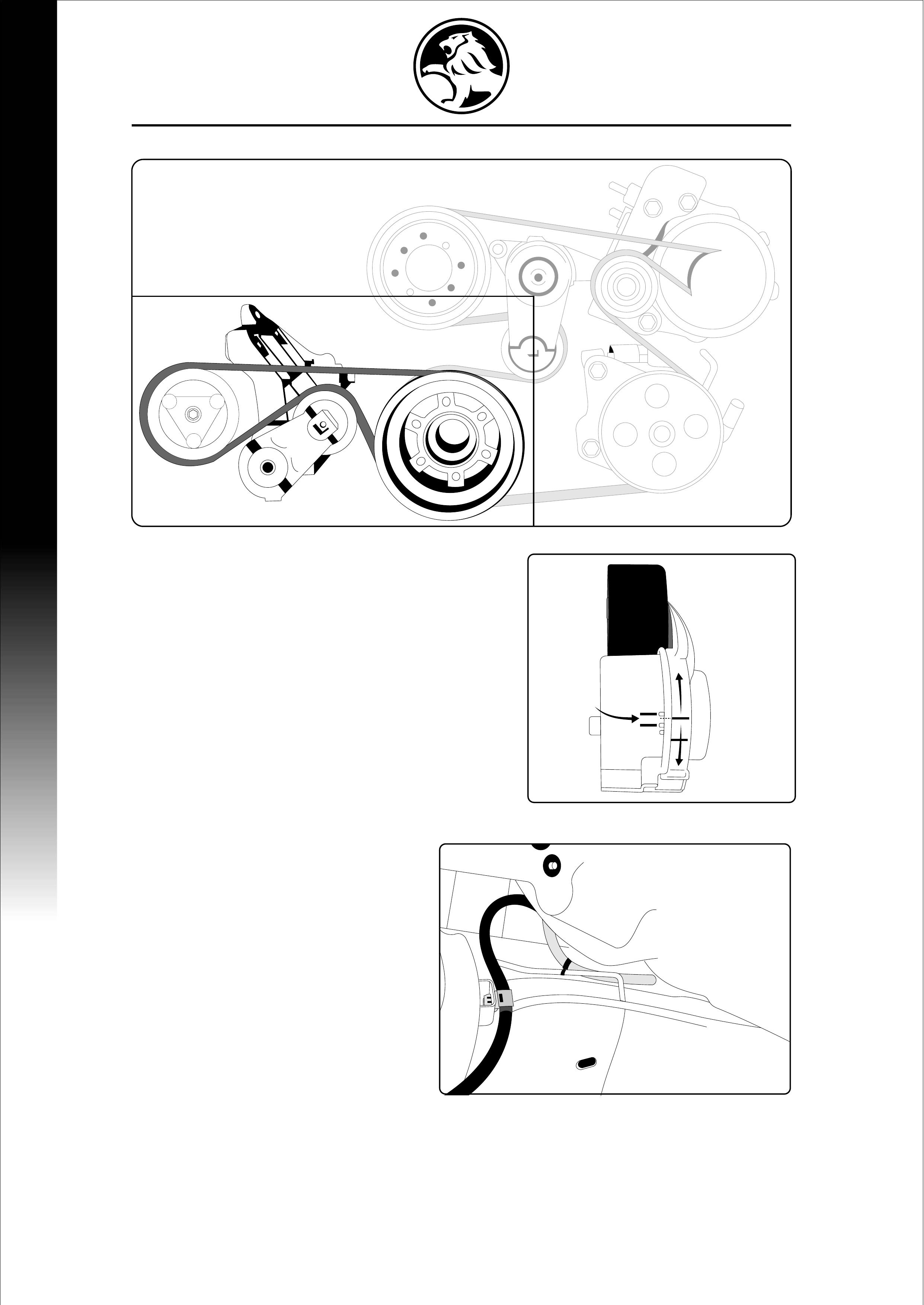
BELT INSTALLATION
a) When Mounting Bracket and Compressor have
been torqued correctly, install Compressor
Drive Belt.
b) Check Belt alignment is correct.
NB: When belt is installed, Tensioner wear
indicators should line up in position indicated
(refer diagram).
Tensioner Position with the Belt (engine at idle).
For Belt wear information refer Service Information
Package.
DRAIN HOSE INSTALLATION
a) Mount Drain Hose to evaporator
outlet and route to left-hand side
Chassis Rail.
b) Using clip supplied (a), clip Drain Hose
to Brake Line above left-hand side
Chassis Rail. Allow Drain Hose to lay
on top of the Chassis Rail.
NB: Ensure that Drain Hose is
routed correctly (refer diagram).
WARNING:
a) Evacuate system and charge with 700grams (+/- 25grams) of R134a refrigerant.
See section 14.0 EVACUATION AND CHARGING PROCEDURE.
b) Leave Charge Machine attached to system and run A/C system checking operation of
following points (see FAULT SOLUTIONS section if one of the following does NOT occur):
- Compressor Clutch engages
- Cool air blows from vents
11.0
12.0
Correct
Position
within the
indicated
span
(a)
RELAY INSTALLATIONRELAY INSTALLATION
12
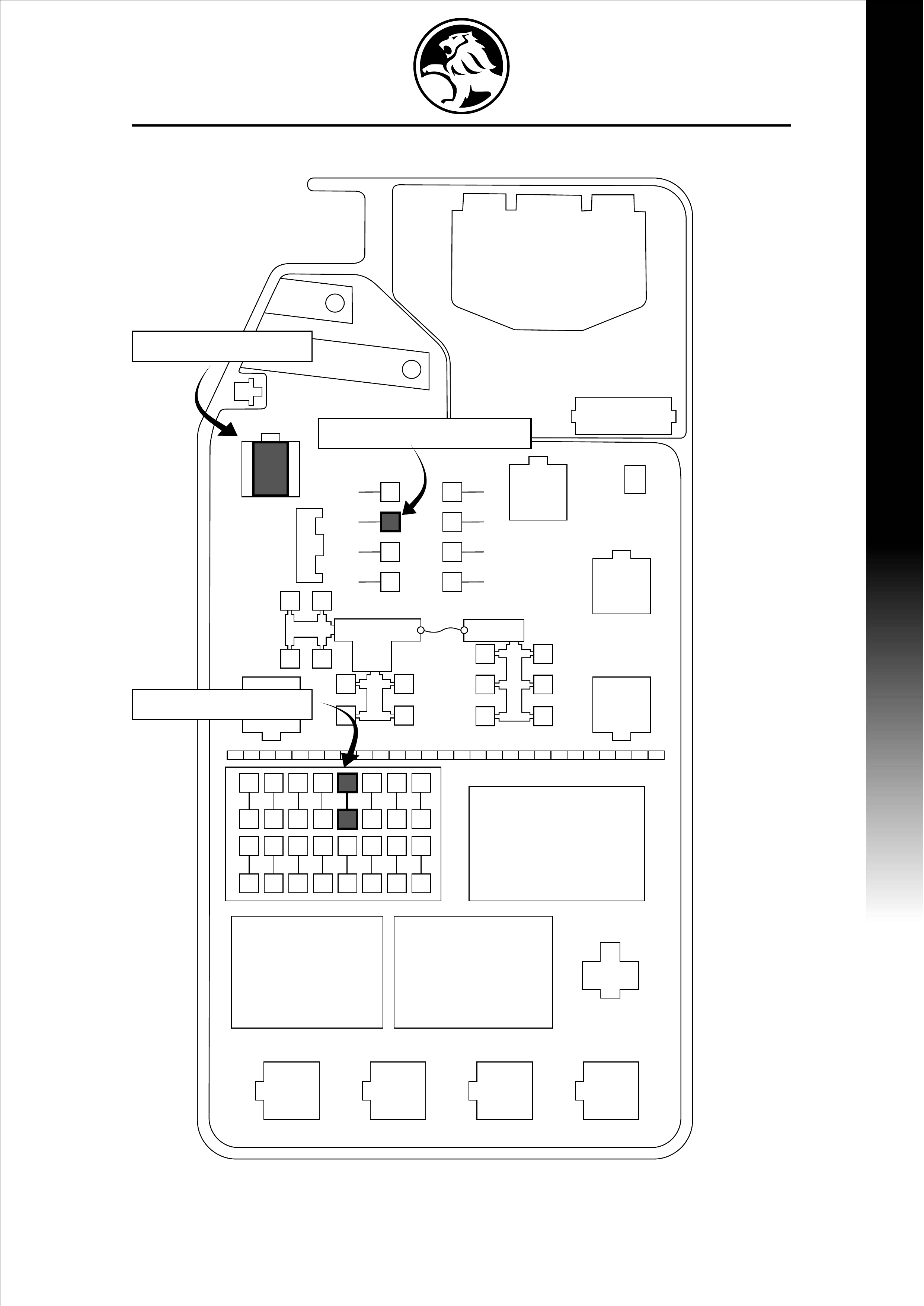
13.0 A/C RELAY LOCATION
A/C Circuit Relay
A/C Slow Burn Fuse (20 AMP)
A/C Fuse (10 AMP)
EVACUATION AND CHARGINGEVACUATION AND CHARGING
13
14.0
NOTE:
1: Gloves, Safety Glasses, Overalls and
Safety Shoes MUST be worn.
2: Work in a well ventilated area.
3: Do not inhale refrigerant.
4: Avoid contact with skin and eyes.
5: Prevent contact of PAG oil with painted
surfaces
6: DO NOT smoke near refrigerant
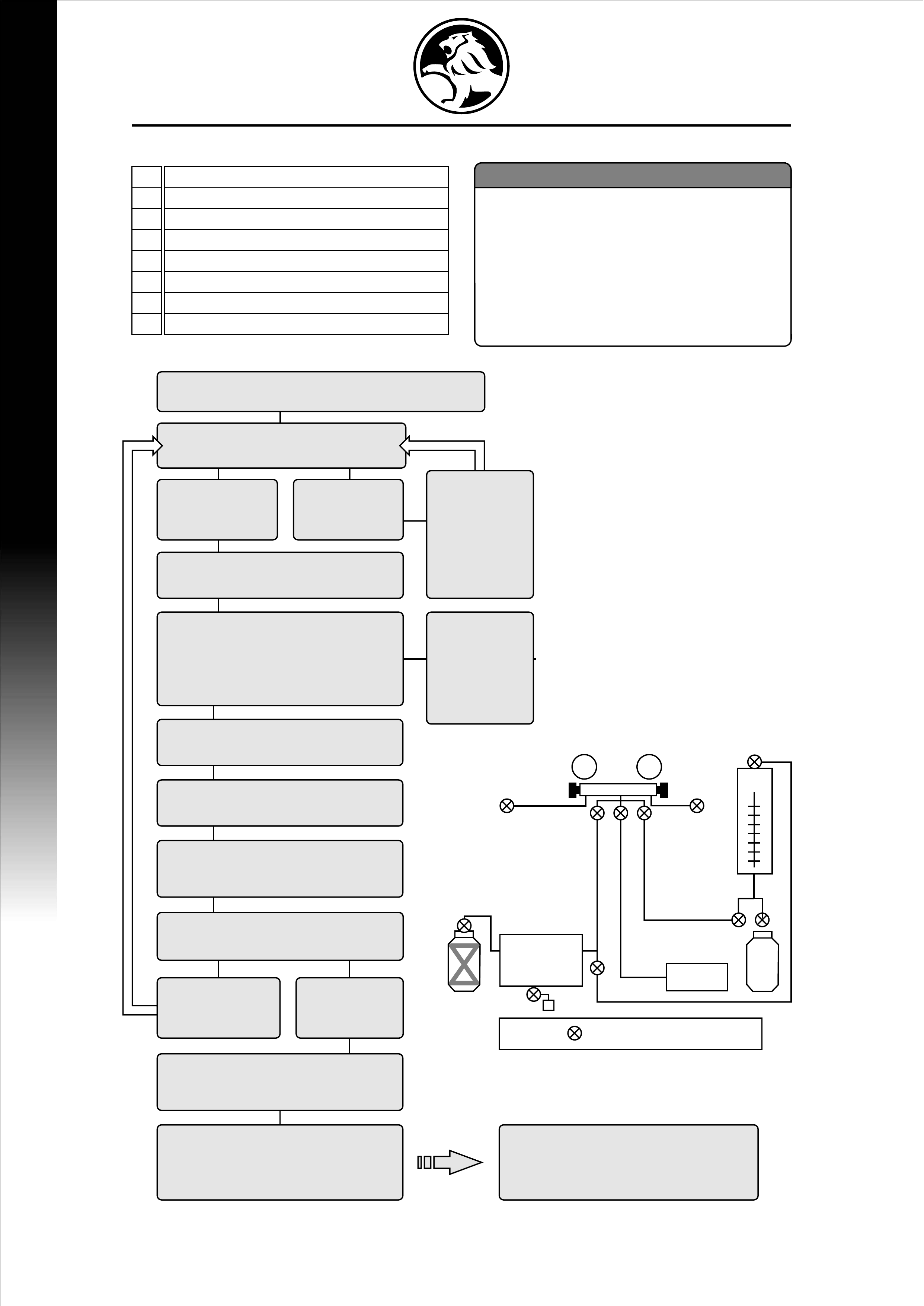
EVACUATION & CHARGING PROCEDURE - R134a
LOW HIGH
A
C
H
REFRIGERANT
RECOVERY
UNIT
REFRIGERANT
RECOVERY
UNIT
NOTE: Indicates stop tap or valve
E F G D
B
A
B
C
D
E
F
G
H
Low Side Gauge Valve
High Side Gauge Valve
Low Side Quick Connect to Plumbing
High Side Quick Connect to Plumbing
Refrigerant Recovery Machine Valve
Vacuum Pump Valve
Refrigerant Charge Valve
Refrigerant Recovery Bottle Valve
EVACUATION PROCESS CONSULT MATERIAL
SAFETY DATA SHEET
(MSDS) FOR
EMERGENCY
PROCEDURES
Switch on Vacuum pump, &
open valve F, then A, C & D
High Pressure
Gauge reads
less than zero
If leak found,
repair & restart
evacuation
Leave valves F, A, C & D open.
then open valve B
Low Side
Gauge
needle rises.
(system
loses
vacuum)
Continue Evacuation for
a minimum of 15 mins
(following evacuation proceedure)
Low Side Gauge is steady.
(system maintaining vacuum)
Open valves A, B & G. Partially
charge system with approx
200 grams of refrigerant
Close Valve G.
Open valves A, B, E & H.
Recover Partial charge
Close Valve H & E.
Open valves A, B, C, D & F,
& continue evacuation process
for 20 min
Evacuate system to -100kPa
Gauge pressure.
Close valves A, B & F.
System must maintain -100kPa
for 15 minutes
Inspect for Leak with
Electronic Leak Detector
High Pressure
Gauge reads
zero or more
No
leaks
found
Blockage
or leak in
system.
Rectify
cause
& restart
procedure
PROCEED TO
CHARGING PROCESS
VAC.
PUMP
VAC.
PUMP
R134aR134a
DIAL-A-CHARGE
MACHINE
DIAL-A-CHARGE
MACHINE
RODEORODEO
14
EVACUATION AND CHARGINGEVACUATION AND CHARGING
EVACUATION & CHARGING PROCEDURE - R134a
WARNING:
1: Never run Compressor without refrigerant in system.
(relies on refrigerant oil circulation for lubrication)
2: Any oil lost during the Refrigerant Recovery Process
must be replaced in the system before Recharging.
3: The R134a A/C system uses PAG (Poly-alkaline glycol)
Lubricating Oil. Always use specified oil for system.
4: Never Charge System through the High Side with the
Compressor running.
CHARGING PROCESS
Open High Side valves B, D, G & Low Side valves C. Open
refrigerant supply & allow Refrigerant to enter system,
not allowing more than specified Charge to enter.
Close High Side valve 'B' & rotate Compressor Drive plate
to ensure no liquid is trapped in Compressor
Start Engine, set to Fast Idle, & activate A/C switch.
Set to Maximum cooling & high fan speed
Open Low Side valve 'A' slowly & complete the charging process.
Close Refrigerant supply when correct charge amount is reached.
CAUTION: Do not allow more than 300 kPa to register
on the Low Side Gauge during charging
Carry out Performance Testing (checking Gauge Pressures)
Refer to workshop manual for appropriate specifications
Close all valves, remove High & Low Side filling hoses from
vehicle. Always recover remainder of refrigerant left in
Guage/Hose assembly
To ensure that the correct amount of charge is maintained in
System, CLOSE High Side valve D (this must be closed) & very
SLOWLY open High Side valve 'B' this process will draw
Refrigerant into Low Side & eliminate excess Refrigerant
retained in High Side Gauge/Hose assembly.
NB:
Check that Engine Cooling Fan operates during
the charging procedure.
Engine Cooling Fan speed will increase as
A/C System pressure rises
FAULT SOLUTIONS
PROBLEM
Insufficient Air Volume
Outlet Air Temperature is High
Compressor not Pumping
FAULT
Blower Motor normal, but Air
Volume Insufficient
Blower Motor Does Not Rotate
High Suction Pressure
Low Suction Pressure
High Discharge Pressure
Low Discharge Pressure
Magnetic Clutch
POSSIBLE CAUSE
- Intake Duct is Obstructed
- Evaporator fins are frosted
- Faulty Blower Switch
- Faulty Blower
- Faulty TXV
- Refrigerant Overcharge
- Faulty TXV
- Refrigerant Leak in System
- Evaporator fins are frosted
(faulty TXV)
- Refrigerant Undercharge
- Compressor Oil Overcharge
- Blockage in system
- Air contamination in system
- Refrigerant Overcharge
- Blockage in system
- Faulty TXV
- Refrigerant Leak in System
- Blockage in system
- Clutch wire not connected
- Refrigerant Undercharge
- Defective fuse/relay/pres. switch
- Faulty Coil
- Belt tension
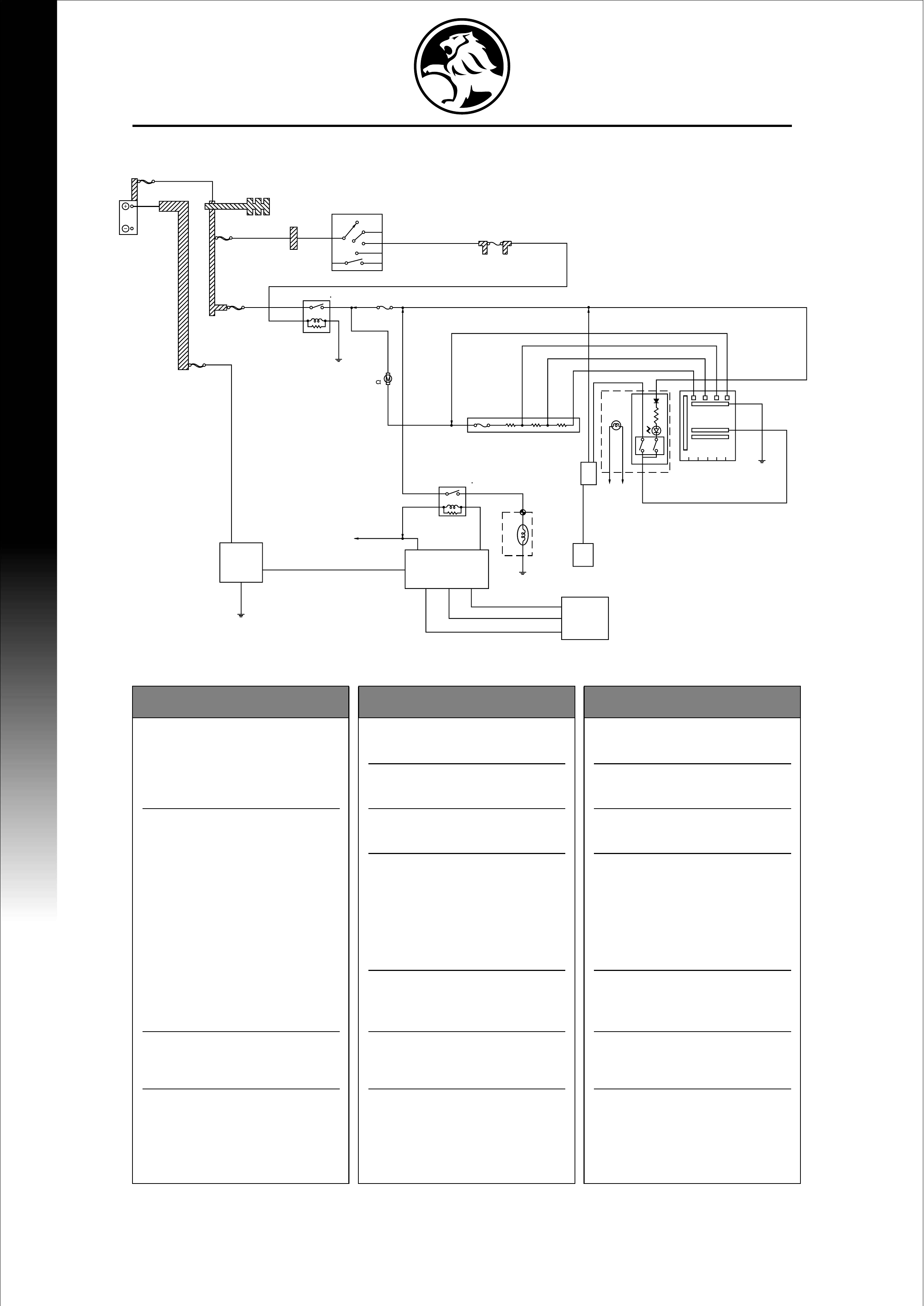
ELECTRICAL
15.0
16.0
ELECTRICAL AND FAULT SOLUTIONSELECTRICAL AND FAULT SOLUTIONS
BATTERY
BUSBAR
NO. 3
BLOWER
30A
40A 5R
RELAY:
HEATER 3
EARTH:
ENG ROOM
RAD . FAN
BLOWER
1 . 04
LH
SW: IGNITION
RESISTOR
ELEC IG
15A
MAIN
140A PA10
E1-01 S1-02
PA01
PA06 PA04 PA11
HA01
QA05
HA02 HA09
HA05
HA08
HA17
290A
QA 15
QX12
(X2 - 49)
(X2 - 1)
( 2 )
( 1 )
( 4 ) (X2 - 33)
(X2 - 25) (X2 - 39) (X2 - 9)
0 . 5BR
RELAY:
A/C COMP 2
ECM
A / C PRESS
TRANSDUCER
( 3 )
( 1 )
( 2 )
0 . 5G / B
0 . 5R
0 . 5B / Y
0 . 5BR
5B
RAD . FAN
EARTH : RAD FAN
FUSE : ECM
0 . 5P / L
0 . 75P / L
0 . 5GR /R
MAGNET
CLUTCH
0 . 5BR / Y
HA19
HA18
259A
709A
510A
HA20
HA10
5
3
3
3
6 5 4
2
2
( 2 )
2OFF
CONTROL LEVER EARTH:
BODY LH
0 . 5W
LO ML MH HI
1
1
1
6
HA07
HA06
HX01
HA04HA21
HA03
E2 - 11
8W
5W 3W
3W / R 3L / R 0 . 5BR
2L / B
1 . 25L / O
0 . 85LG
0 . 85L / W
0 . 5BRHA11
0 . 3G/ R
0 . 5G / R
HA13
0 . 3R / G
BA 12
BA 39
3B
SW:A / C
HA25
HX02
0 . 5R/ L
THERMO
PIM
WELD SPLICE 1
WELD SPLICE 2
1
3
4 2
A / C
10A
0.5W
3B / Y
B2
OFF
ACC
IG2
ST
IG1
B1
8B / R
IGN . 2
50A
1 . 25B
3L / R3L / B
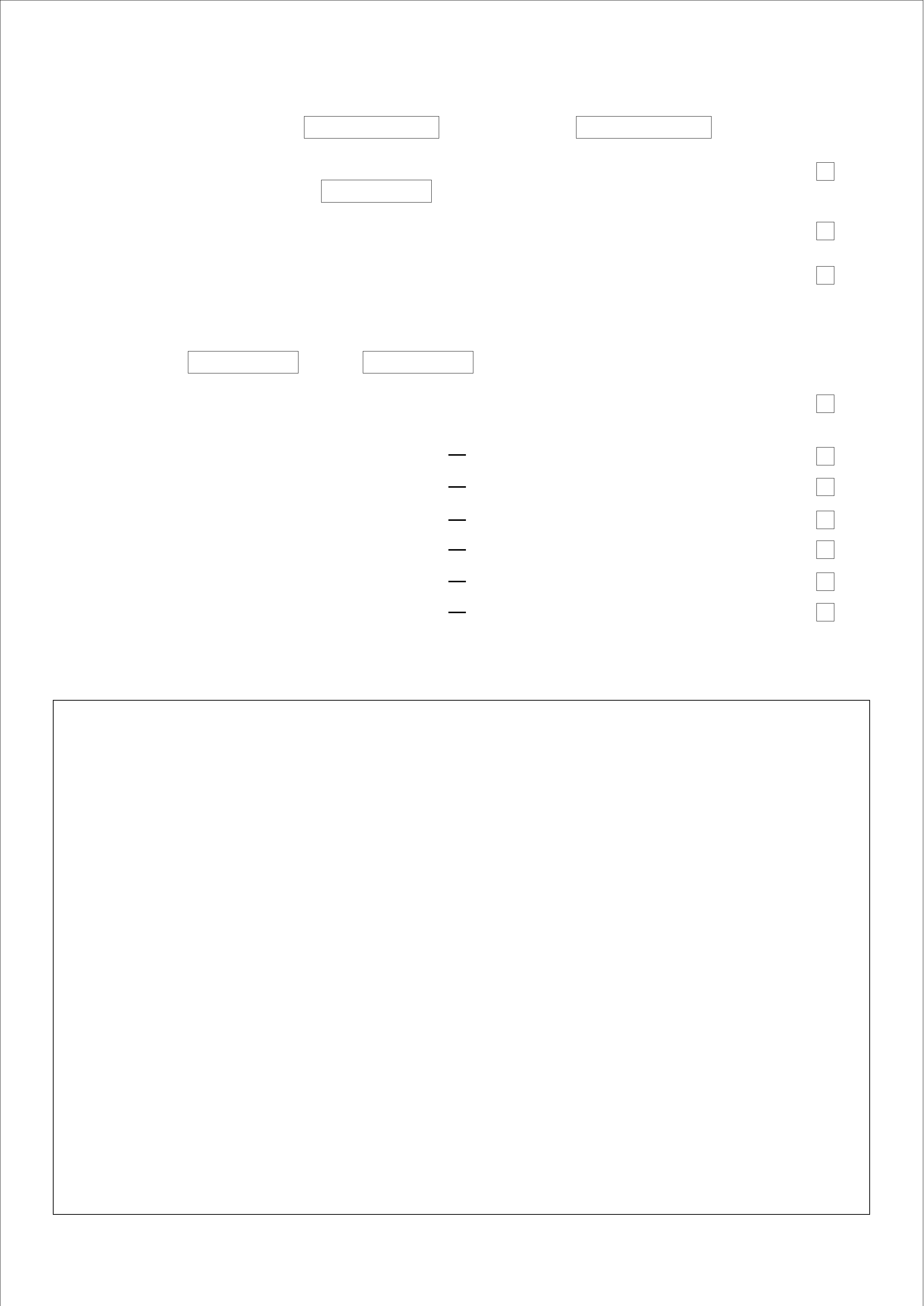
NOTES
Instruction No: 25186958 Delphi No: 25186529
!Calibrated Refrigerant Charging Equipment must be used when charging A/C
system. - Cal. date: Next Cal. due:
!Ensure correct Charge Amount is installed in the Refrigerant System.
Charge Amount used gas.
!Ensure all Fittings and Mountings are installed to correct torque amount.
!Check that clearance between Aluminium Pipes (Liquid) and Sheet Metal/s is
adequate.
!When Vehicle has been charged record Gauge Readings.
High: Low:
!Check Vehicle Heater Air Conditioning Controls operate correctly.
INSTALLATION CHECKLIST
Heater On/Off
Recirc Outside Air Control
Fan Speeds
Demister
A/C On/Off
Condenser Fan (Activated 1520kpa)