CCOPYRIGHT HOLDEN 2004
Reproduction in whole or part prohibited
without written approval of Holden LTD
FD1282 27AUG04
Sound System Upgrade
Owner's Manual

Contents
Amplifier............................................................................................................3
Introduction .................................................................................................3
Amplifier Controls .......................................................................................3
General Amplifier Controls ..........................................................................3
Operating Indicators ...................................................................................3
Bass Boost..................................................................................................4
Crossover Selector Switch..........................................................................4
Level (Gain) ................................................................................................4
Amplifier Connections.................................................................................5
Technical Specifications (Amplifier) ............................................................5
Subwoofer (Optional)........................................................................................6
Introduction .................................................................................................6
Subwoofer Controls ....................................................................................6
Tuning.........................................................................................................6
Subwoofer Connections..............................................................................7
Technical Specifications..............................................................................7
Page 2 of 8
Amplifier
Introduction
The Holden accessory amplifier
is a key element in the Holden
sound system upgrade package. The
amplifier has several adjustment features
that allows the user to customise the audio
system to their specific requirements. The following
details are presented to assist users to customise the audio system output.
Amplifier Controls
General Amplifier Controls
All of the amplifier adjustable features are set up so that customisation is
possible on the front speakers only or the rear speakers only. When the
optional subwoofer is present, the amplifier will not change the subwoofer
settings. The subwoofer has a separate built-in amplifier and adjustable
features.
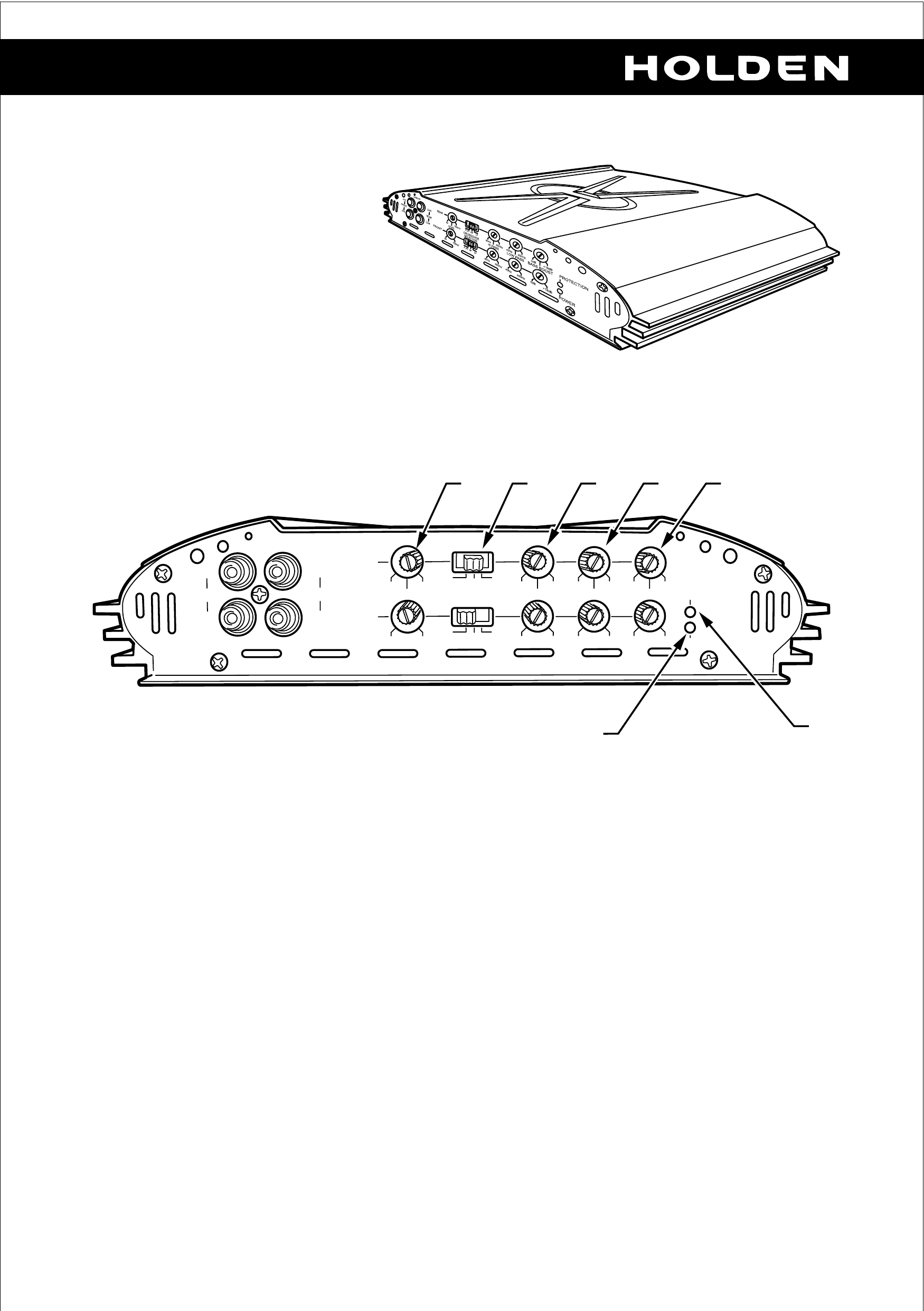
Operating Indicators (1 & 2)
Green LED: The indicator is only illuminated when the amplifier is active.
Red LED: The indicator is only illuminated when the amplifier has a
fault or a failure. Under normal operation, the LED is inactive.
Page 3 of 8
FRONT
CH1
CH2
LINE-IN
CH3
REAR
CH4
REAR
FRONT
LEVEL
8V 100mV
8V 100mV
CROSSOVER
SELECTOR
FLAT HP LP
FLAT HP LP
65Hz 450Hz
HI PASS
65Hz 450Hz
40Hz 450Hz
LOW PASS
40Hz 450Hz
0dB +18dB
0dB +18dB
BASS BOOST
PROTECTION
POWER
7 4 5 6 3
2
1

Bass Boost (3)
By increasing the bass boost (3) from 0dB to 18dB, the amplifier is effectively
intensifying the low frequency (bass) sounds.
NOTE: The more bass that is introduced into the audio system, the more
power is consumed. The audio system has a set power capacity, therefore
bass increases tend to reduce the overall volume output of the amplifier.
SUGGESTION: If the audio system has the optional subwoofer fitted, it is
possible to decrease the bass boost on the amplifier (door speakers) and gain
on volume in the passenger compartment whilst maintaining sufficient bass
via the subwoofer.
Crossover Selector Switch (4)
The crossover switch (4) allows the frequency of the output signals from the
amplifier to be adjusted.
FLAT setting: The output signals from the amplifier are in the same proportion
as the input signals. When "FLAT" is selected, the "HI PASS" knob (5) and
"LOW PASS" knob (6) are inactive. FLAT is the factory default.
HP Setting: By selecting this position, adjustment is possible with the "HI
PASS" knob (5). By adjusting the "HI PASS" knob from 65Hz to 450Hz, this is
effectively removing lower frequencies (bass) from the signal that is being
amplified and sent to the speakers.
SUGGESTION: If the audio system has the optional subwoofer fitted, it is
possible to increase the "HI PASS" setting on the amplifier (door speakers)
and gain on volume in the passenger compartment, whilst maintaining
sufficient bass via the subwoofer.
LP Setting: By selecting this position, adjustment is possible with the "LOW
PASS" knob (6). By adjusting the "LO PASS" knob from 40Hz to 450Hz, this
is effectively removing higher frequencies from the signal that is being
amplified and sent to the speakers.
NOTE: It is not advisable to use the "LO PASS" setting in this vehicle
application.
Level (Gain) (7)
It is not recommended that the gain (7) is changed
from the factory preset setting (2 Volts) as shown.
Page 4 of 8
REAR
FRONT
LEVEL
8V 100mV
8V 100mV
Level (Gain) continued
NOTE: It is important to have both front and rear level knobs adjusted to the
same position to ensure the volume output of the speakers is equal in both front
and rear seating positions.
Increasing gain will not increase the overall volume of the audio system.
Adjustments will only cause the maximum output to be achieved earlier in
volume adjustments of the headunit. For example, factory setting (2V) will
achieve maximum volume with a headunit setting of approximately 45. A
customised setting of 200mV will achieve maximum volume with a headunit
setting of approximately 30. Increasing gain will also increase susceptibility to
electrical interference.
Decreasing gain has the opposite effect of increasing gain. (Decreasing gain is
not recommended.)
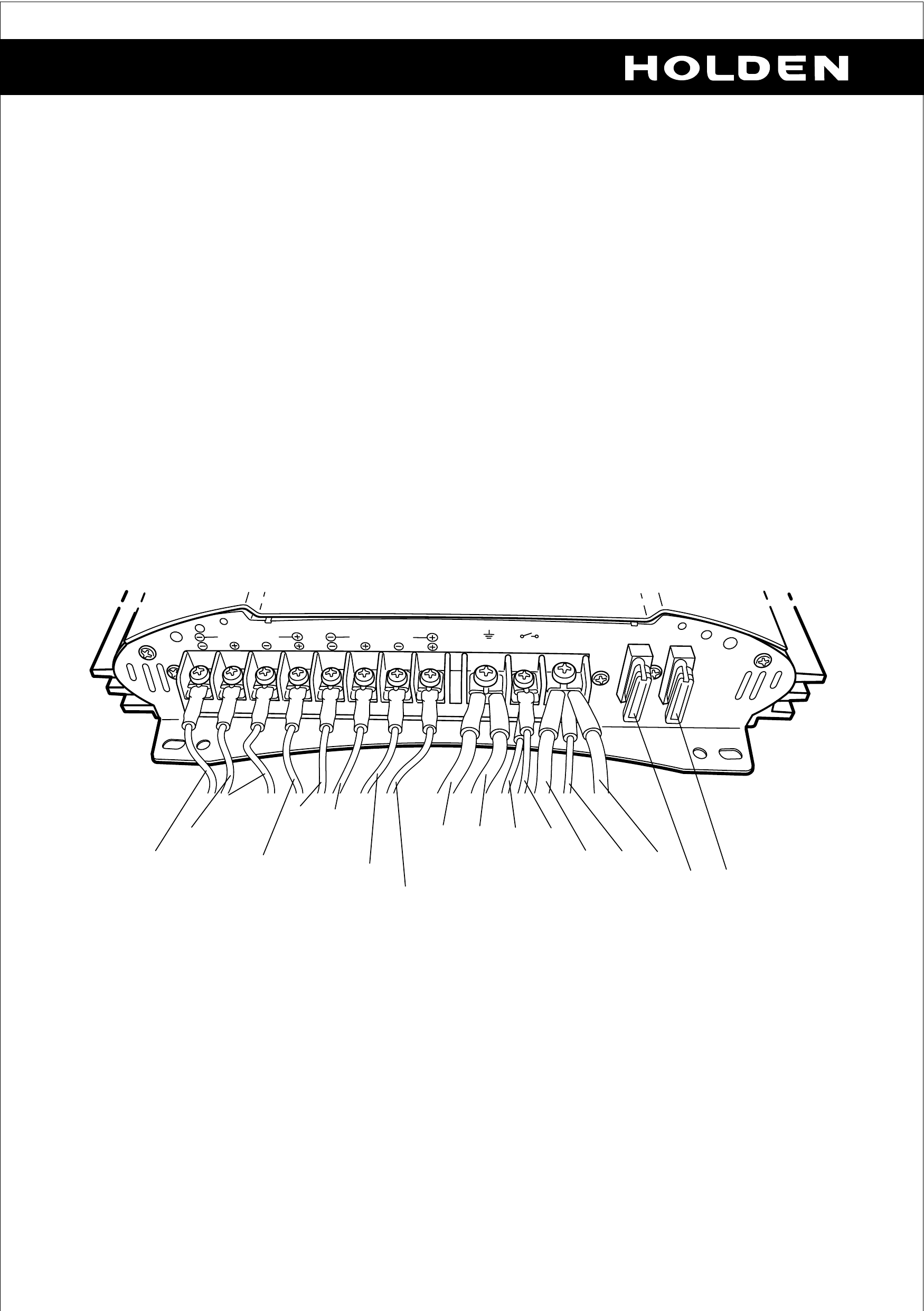
Amplifier Connections
Technical Specifications
Quad mode - max power 4 x 100 Watt / 4 Ohms
Quad mode - RMS power 4 x 50 Watt / 4 Ohms
Stereo mode - max power 2 x 320 Watt / 4 Ohms
Stereo mode - RMS power 2 x 160 Watt / 4 Ohms
Frequency response 10 Hz to 30,000 Hz
Signal to Noise Ratio Greater than 90 dB
Stability 2 Ohms
Input sensitivity 0.1 to 8.0 Volts
Low-pass filter 40 to 450 Hz
Hi-pass filter 65 to 450 Hz
Bass boost 0 to 18 dB Page 5 of 8
REAR
BRIDGE MODE
CH4
CH3
CH2
CH1
BRIDGE MODE
FRONT
GROUND
REMOTE
SUPPLY
+12V
FUSE FUSE
ORANGE
DARK BLUE
BROWN/WHITE
LIGHT GREEN
DARK GREEN
BROWN
GREY
BLACK 4mm
WHITE 2mm
RED 4mm
RED 2mm
RED 4mm
25 AMP
25 AMP
YELLOW
BLACK 4mm
WHITE 2mm
Page 6 of 8
Subwoofer (Optional)
Introduction
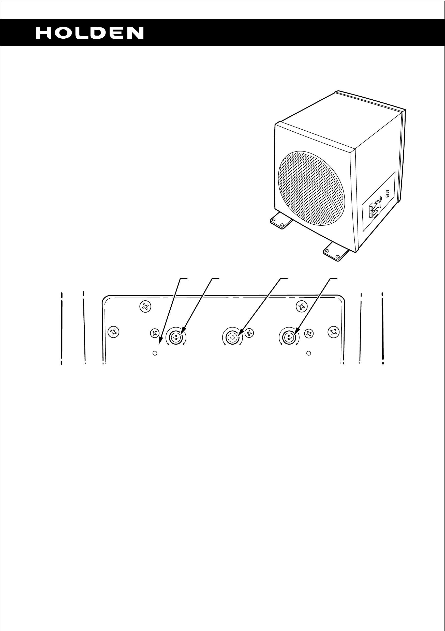
The Holden accessory subwoofer is an optional
element in the Holden sound system upgrade
package. The subwoofer has several adjustment
features that allows the user to customise the
audio system to their specific requirements. The
subwoofer does not have a factory preset and
requires tuning prior to completion of installation.
Subwoofer Controls
Tuning
NOTE: It is desirable to have the listener in the passenger compartment who
instructs an assistant tuning the subwoofer.
The following procedure is provided to assist with the tuning process.
1. Set the controls to the following positions.
a. Phase (2) at 0°
b. Crossover (3) at 120 Hz
c. Gain (4) at minimum (8 Volts)
2. Turn on the audio system and select a familiar music track from a CD.
3. Turn up your audio system volume to a moderate to high listening level.
POWER
ISSAC
LIMITER
PHASE
180°0° 120Hz60Hz 0.2V 8V
CROSSOVER GAIN
4321

The remaining tuning procedure, steps 4 to 5, may involve several
iterations in order to achieve an optimal bass sound. (This will depend on
listener preferences.)
4. Slowly turn up the gain control (4) until you clearly hear an increase in the
bass level.
5. Using the crossover control (3), adjust the crossover frequency to produce
a well-balanced bass sound.
6. Adjust the phase control (2) so that the bass blends as best as possible
into the overall sound and is not heard as a distinct source. The
recommended setting in this application is 0 degrees.
7. Check for overdriving of the subwoofer.
a. Turn the bass control on the headunit to maximum.
b. Increase the volume on the audio system to maximum undistorted
sound inside the passenger compartment.
c. Overamplification caused by a too a high gain setting (4) will lead to
distorted reproduction and can irreparably damage the loudspeaker. If
the indicator LED (1) flashes with the music, then it is recommended
to reduce the gain setting (4). If gain changes are required, repeat
steps 4 and 5.
IMPORTANT: Maximum gain is at 0.2 Volts, minimum gain is at 8
Volts.
Subwoofer Connections
+12V
20
FUSE
20A
HIGH LEVEL
INPUT
LINE INPUT
L
-
+
R
-
+
L
R
Page 7 of 8
BLACK
(3mm)
WHITE
(0.5mm)
RED
(3mm)
RED RCA
CONNECTOR
BLACK RCA
CONNECTOR
Refer to your Holden Dealer for further information.
Holden Ltd
ABN 84 006 983 232
241 Salmon Street Port Melbourne
Victoria 3207 Australia
Subsidiary of General Motors Corp
All correspondence to:
PO Box 1714 Melbourne
Victoria 3001 Australia
Telephone (03) 9647 1111
Facsimile (03) 9647 2550
Please note that all information, illustrations and specifications in this Handbook are based
on the latest production information available at the time of printing.
Holden reserves the right to make any changes at any time without notice and without incurring any obligation.
Technical Specifications (Subwoofer)
Max power 140 Watts
RMS power 70 Watts
Nominal impedance 4 Ohms
Sensitivity (SPL @ 100 Hz) 136 dB
Phase 0 to 180 degrees
Crossover 0 to 120 Hz
Gain 0.2 to 8.0 Volts
Fuse 20 Amps