NOTE: This Cruise Control Package MUST NOT be
installed to vehicles fitted with traction control.
1. Disconnect vehicle battery.
NOTE: To reinstate the audio system the security
code will be required.
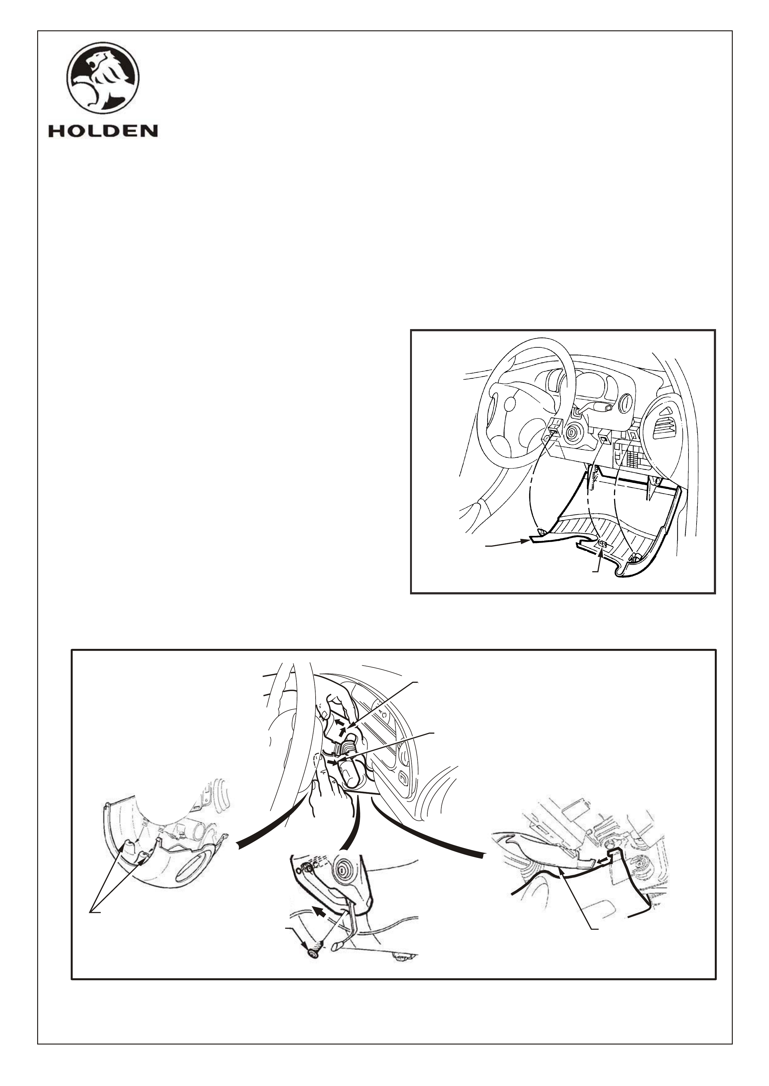
2. Adjust steering wheel to upper most position.
Grasp right hand side of lower cover panel firmly
and pull towards rear of vehicle. Repeat procedure
for left hand side of cover so cover hangs open,
refer fig. 1.
3. Adjust steering wheel to lower most position.
4. Remove single screw from lower steering column
cover, refer fig. 2.
5. Remove upper and lower steering column covers,
refer fig. 2.
TOOLS REQUIRED:
Hole saw (20mm), Centre Punch, Phillips Head Screw Driver, Flat Blade Screwdriver, 10mm Socket,
TECH 2 (optional), Radio Removal Tool (179 1308 0000), Torx Bit T25 Corrosion Protection Paint.,
FITTING INSTRUCTIONS FOR
VX SERIES II CRUISE CONTROL PACKAGE,
5.7L ALLOY V8,
Part No. 92144548
FD1026
19OC01
COPYRIGHT
Page 1 of 13
G527V8
HOLDEN SERVICE PARTS OPERATIONS
Reproduction in whole or part
prohibited without written approval
Division of HOLDEN Ltd ACN 006 893 232
FIGURE 2
SCREW
LOWER COVER MUST
BE DISENGAGED
FROM COLUMN LUGS
AS SHOWN
DISENGAGE UPPER
COVER FROM
LOWER COVER
PUSH LOWER
COVER IN THIS
DIRECTION
PULL UPPER
COVER IN THIS
DIRECTION
FIGURE 1
INSTRUMENT
PANEL
LOWER
COVER LOCATING CLIP
3 PLACES
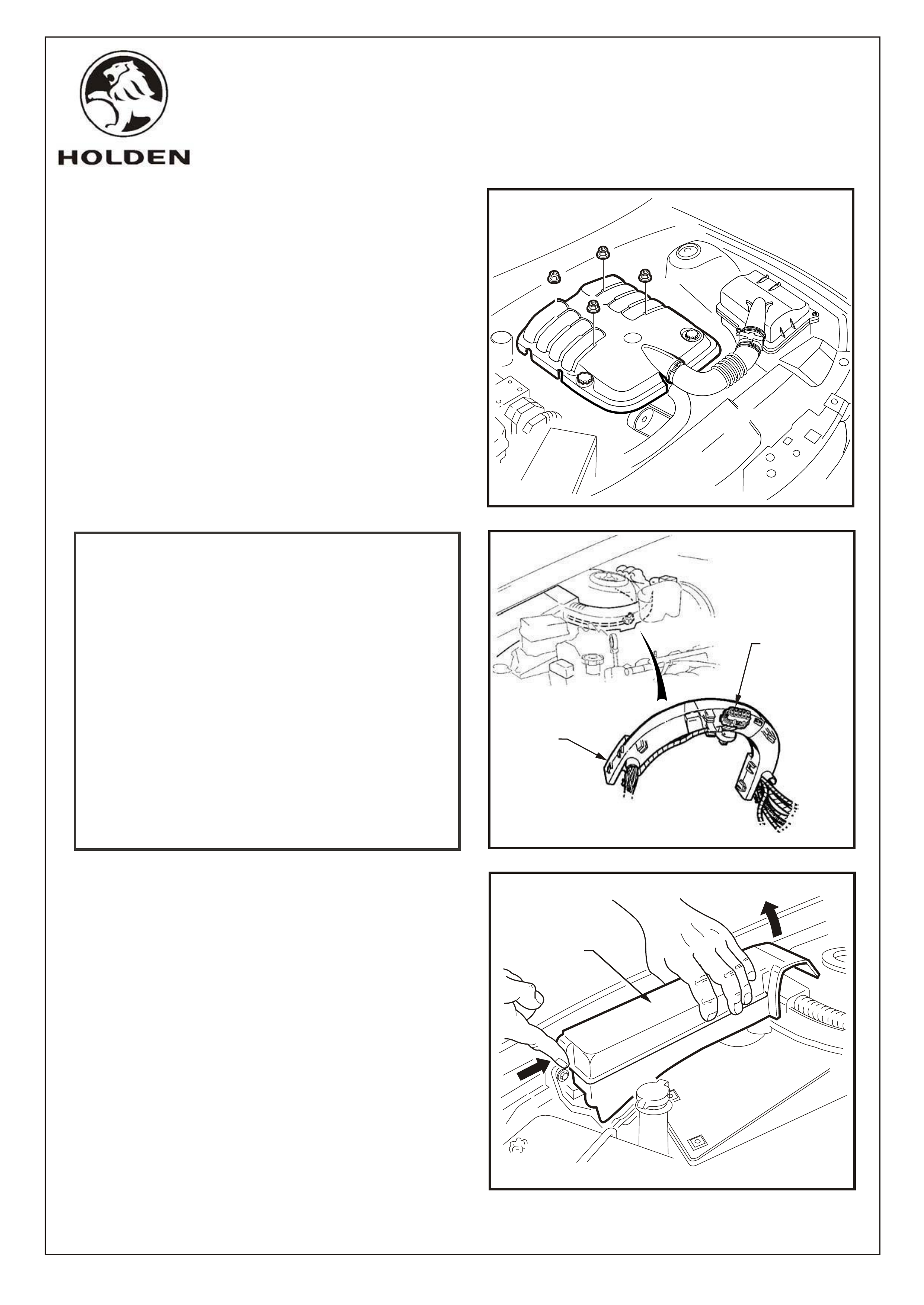
6. Remove four nuts securing the engine dress cover
and remove cover, refer Fig. 3.
NOTE: For MANUAL TRANSMISSION vehicles also
refer to page 12 of these instructions for additional
procedures.
IMPORTANT: Check if stepper motor connector is
clipped to underside of strut tower former, as part of
the original wiring harness, refer fig. 4.
If connector exists, go to step 57.
If connector does not exist, continue installation as
described below.
Use Tech 2 to determine if two globes are already
fitted to cruise control lamps in instrument cluster
(If TECH 2 is not available follow steps 24 to 28 on
page 5 to determine if globes are fitted).
If globes are already fitted, go to step 57.
If globes are not fitted but stepper motor connector
does exist, go to step 24.
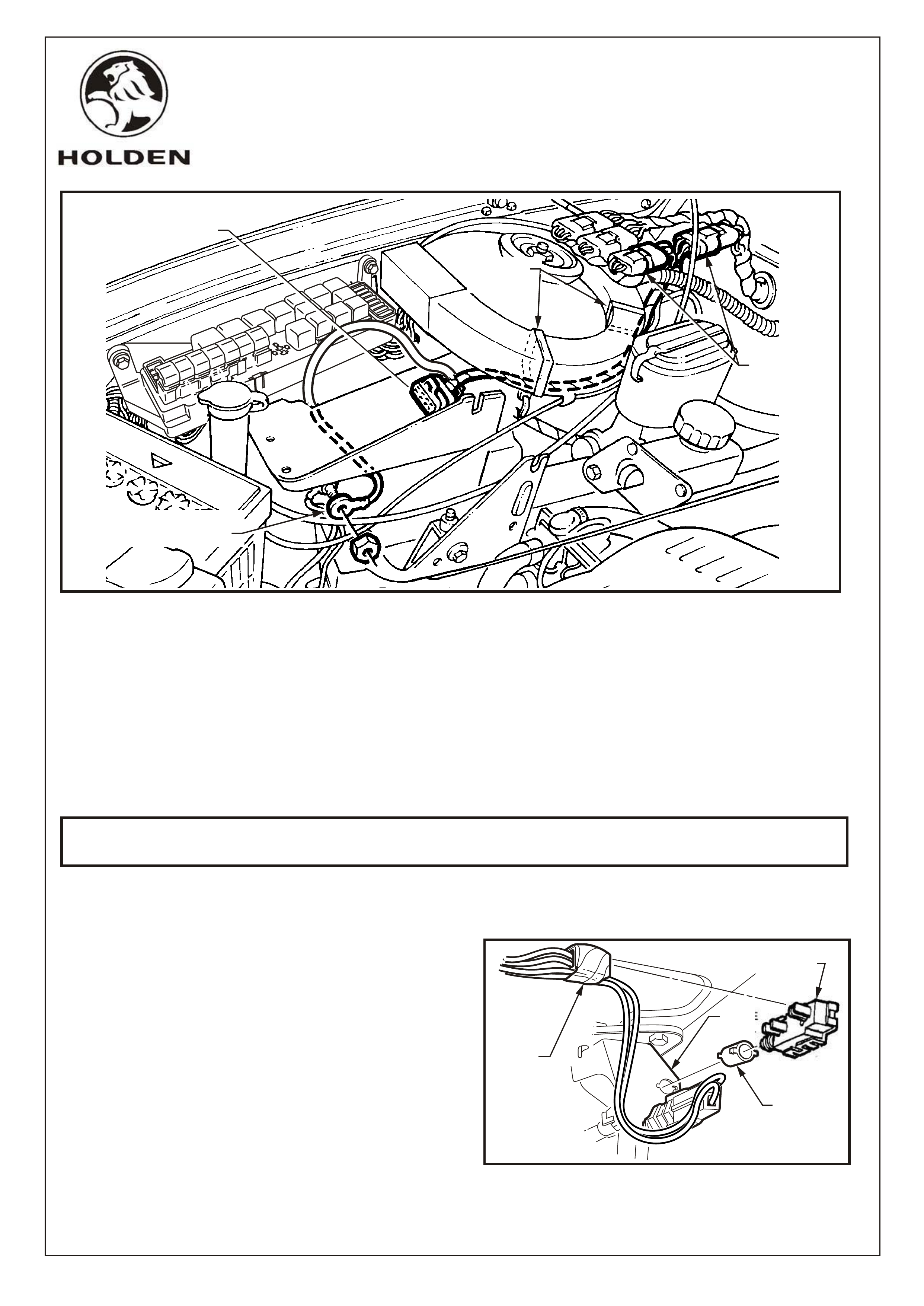
7. Unclip and remove engine compartment relay box
cover, refer fig. 5.
FIGURE 5
COPYRIGHT
Page 2 of 13
G527V8
HOLDEN SERVICE PARTS OPERATIONS
Reproduction in whole or part
prohibited without written approval
Division of HOLDEN Ltd ACN 006 893 232
FIGURE 4
STEPPER
MOTOR
CONNECTOR
STRUT
TOWER
FORMER
REMOVE
RELAY BOX
COVER
FIGURE 3
FD1026
19OC01
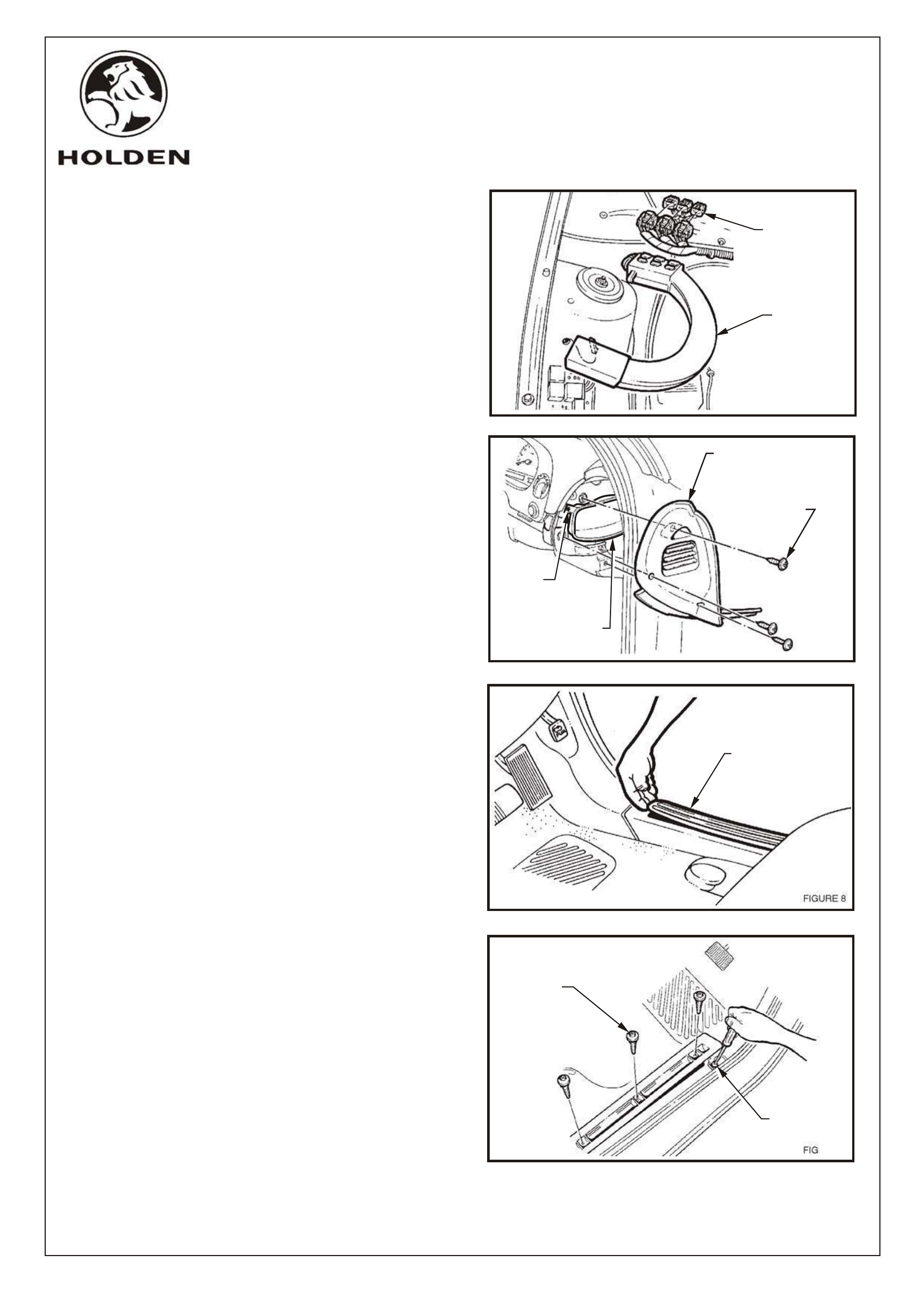
8. Disconnect 3 main wiring harness connectors at RH
strut tower and unclip connectors from former
endcap, refer fig 6.
9. Disconnect former from strut tower, refer fig.6.
10. Swing former inboard to access area directly behind
strut tower, where bonnet release cable comes
through firewall.
11. Remove 3 screws securing instrument end cap and
remove end cap, refer fig. 7.
12. Remove RH rocker panel cover insert, refer fig. 8.
13. Remove front three TORX head screws and loosen
rear most screw with TORX bit T25, refer fig. 9.
14. Lift front of RH inner rocker panel cover and remove
screw securing the shroud lower trim assembly to
the rocker panel, refer fig. 9.
FIGURE 6
WIRING
HARNESS
FORMER
MAIN WIRING
HARNESS
CONNECTORS
COPYRIGHT
Page 3 of 13
G527V8
HOLDEN SERVICE PARTS OPERATIONS
Reproduction in whole or part
prohibited without written approval
Division of HOLDEN Ltd ACN 006 893 232
FIGURE 7
INSTRUMENT
END CAP RIGHT SIDE
VENTILATION DUCT
SCREW
SCREW
(3 PLACES)
FIGURE 9
TORX HEAD
SCREW
(3 PLACES)
SCREW
FIGURE 8
ROCKER PANEL
COVER INSERT
FD1026
19OC01
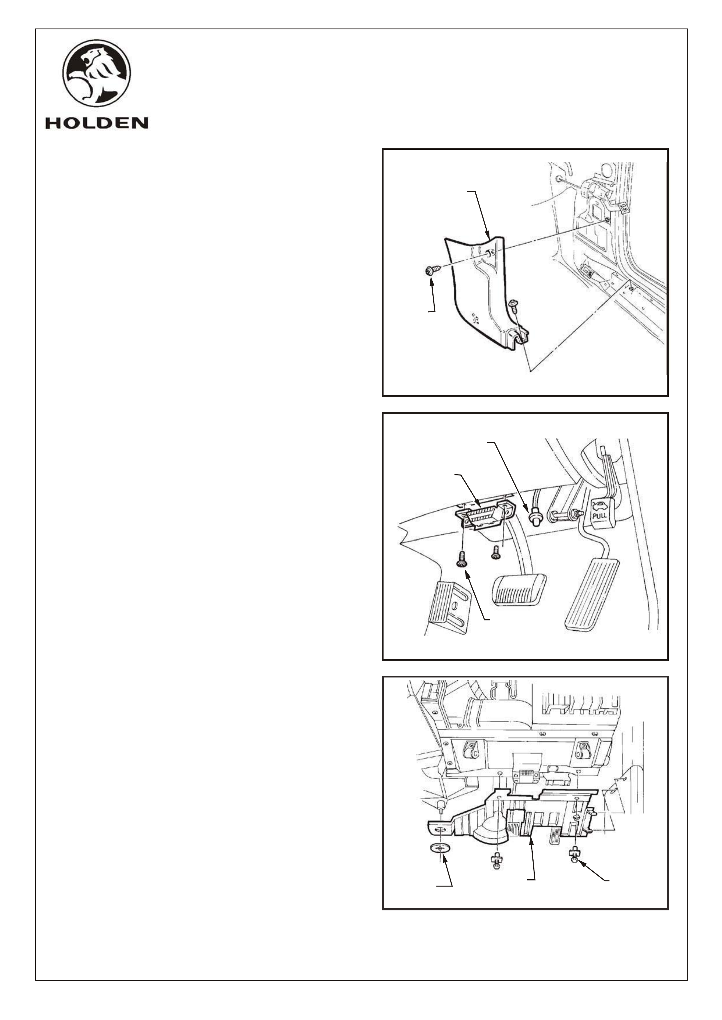
15. Remove the upper retaining screw, from behind
hood release lever, and remove shroud lower trim
assembly, refer fig. 10.
16. Remove 2 screws securing diagnostics connector t o
instrument panel lower trim and allow connector to
hang, refer fig. 11.
17. Remove 2 scrivets and on vehicles with automatic
transmission, prise off retaining button and detach
the footwell upper closing panel, refer fig. 12.
18. Where fitted, remove front footwell lamp.
FIGURE 10
SCREW
(2 PLACES)
RH SHROUD LOWER
TRIM ASSEMBLY
COPYRIGHT
Page 4 of 13
G527V8
HOLDEN SERVICE PARTS OPERATIONS
Reproduction in whole or part
prohibited without written approval
Division of HOLDEN Ltd ACN 006 893 232
R.H.F. FOOTWELL LAMP
WHERE FITTED
DIAGNOSTICS
CONNECTOR
SCREW
(2 PLACES)
FIGURE 11
FIGURE 12
SCRIVETS
(2 PLACES)
FOOTWELL
UPPER CLOSING
PANEL RIGHT SIDE
RETAINING
BUTTON
FD1026
19OC01
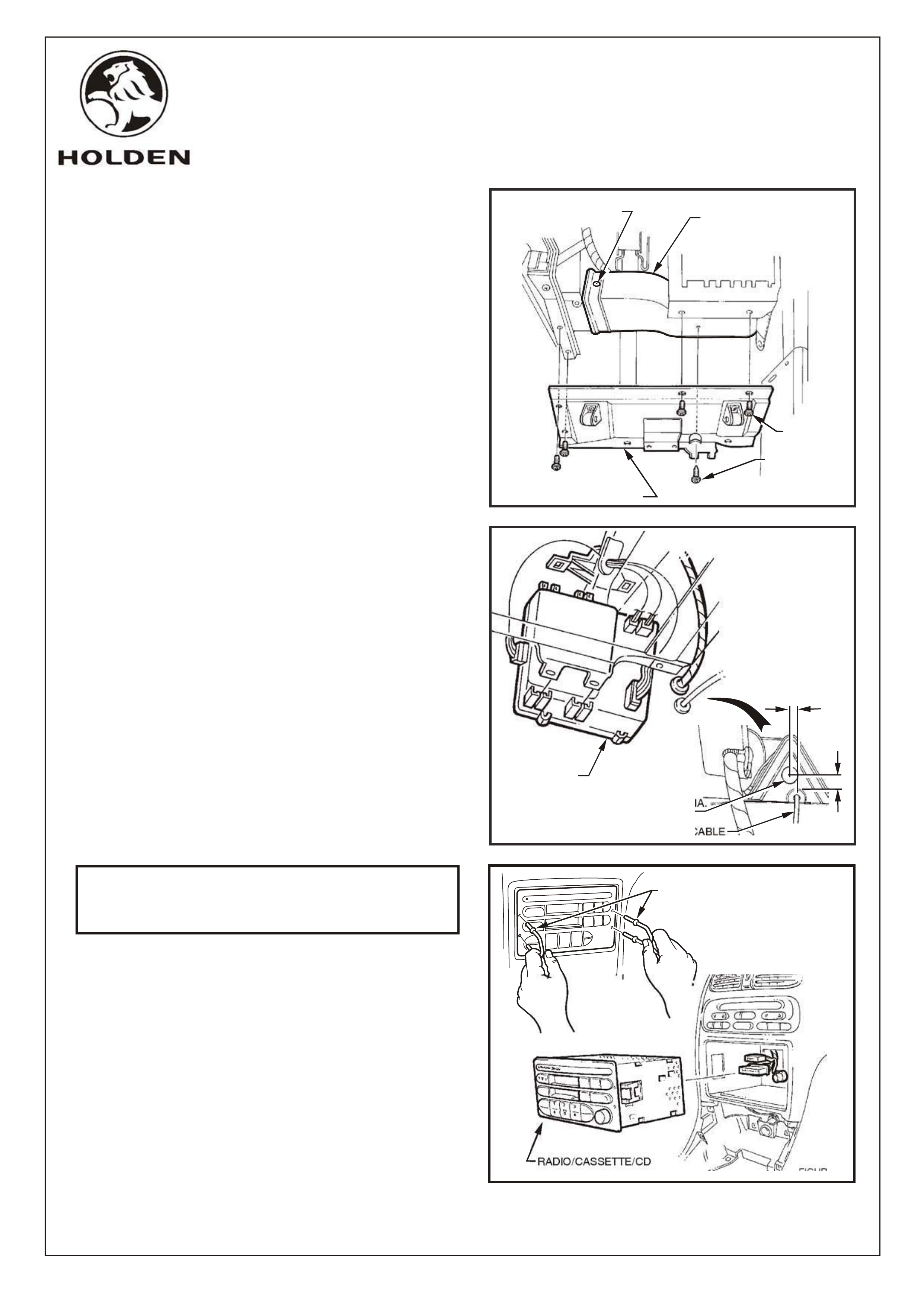
FIGURE 13
SCREW
(4 PLACES)
SELF TAP
SCREW
INSTRUMENT PANEL
LOWER TRIM RIGHT SIDE
VENTILATION DUCT
SCREW
REMOVE BCM
FROM MOUNT
DRILL
20,0 DIA.
HOLE
BONNET RELEASE CABLE
5.0
20.0
FIGURE 14
COPYRIGHT
Page 5 of 13
G527V8
HOLDEN SERVICE PARTS OPERATIONS
Reproduction in whole or part
prohibited without written approval
Division of HOLDEN Ltd ACN 006 893 232
19. Remove 5 screws securing instrument panel lower
trim RHS and remove panel, refer fig. 13.
20. Remove 2 screws securing ventilation ducts, refer
figs. 7 and 13, and remove ducts.
21. Detach BCM from mount, disconnect wiring
connectors and remove BCM, refer fig. 14.
22. Mark and centre punch hole location on firewall,
above bonnet release cable, as per fig. 14. Prior to
drilling, cover carpet to protect from metal filings.
Drill 20mm dia. hole with hole saw, deburr and coat
bare metal with anti-corrosion primer.
23. Insert cruise control patch harness (Part
No.92057293) through drilled hole, from engine
compartment side and seat grommet in hole.
NOTE: If TECH 2 is not available follow steps 24 to 28
to determine if cruise control warning lamp globes are
fitted.
24. Remove radio/cassette/CD from instrument panel
using service tool 179 1308 0000.
Disconnect antenna and if fitted, diversity antenna,
refer fig. 15.
25. Remove rubber cap from transmission console and
remove two screws from transmission console.
Prise out transmission console, disconnecting
power windows harness if required.
FIGURE 15
RADIO/CASSETTE/CD
RADIO REMOVAL TOOL
FD1026
19OC01
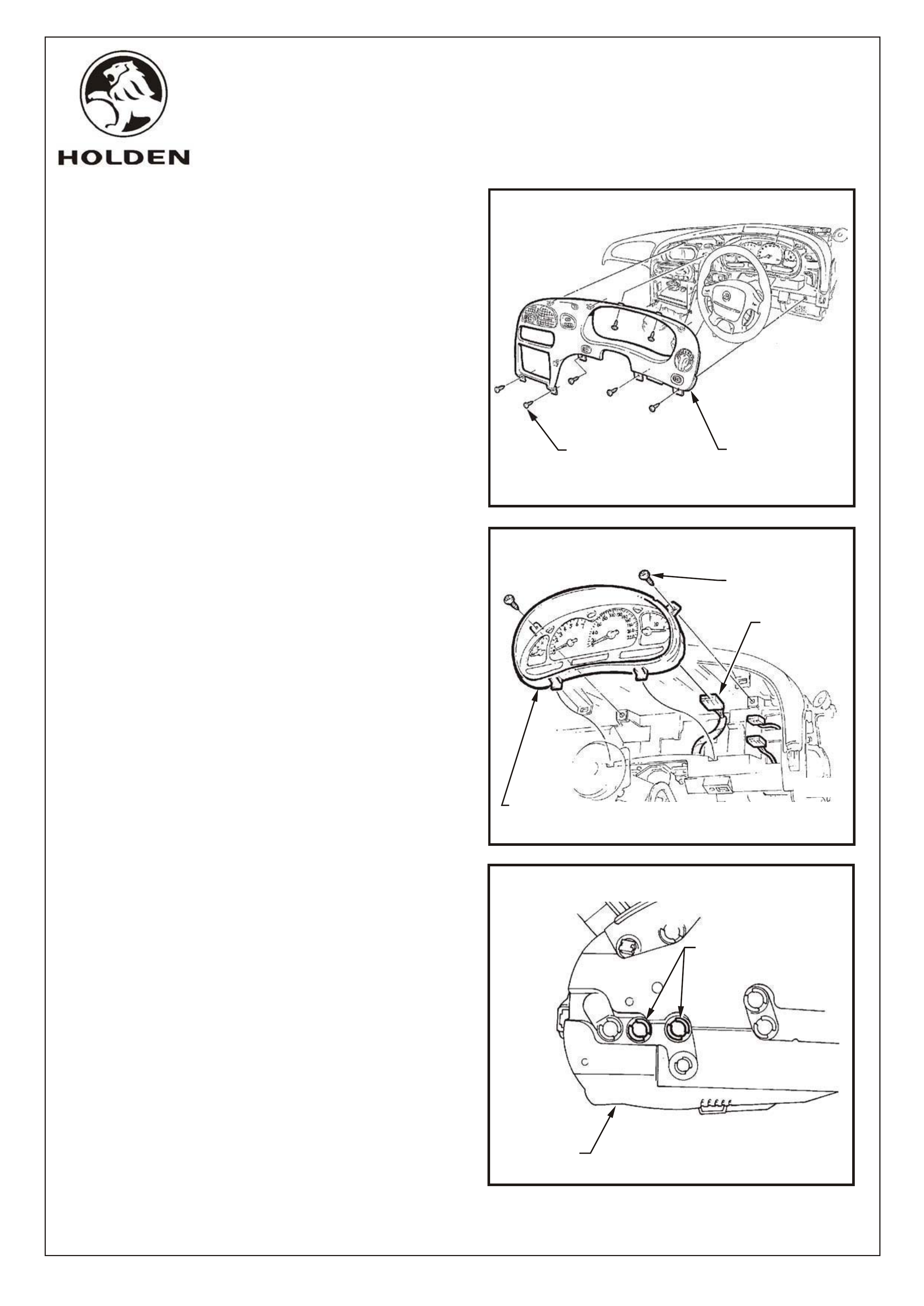
26. Remove the seven screws retaining the instrument
facia assembly, and pull facia from retaining clips,
refer fig. 16.
NOTE: Disconnect the headlamp switch connector,
fog lamp switch connector (if fitted), trip computer switch
connector (if fitted), hazard switch connector from main
wiring harness, before removing instrument facia
assembly.
27. Remove 2 screws securing the instrument cluster,
and disconnect instrument cluster connector,
remove instrument cluster, refer fig. 17.
28. Install 2 globes for cruise control lamps to rear of
instrument cluster, refer fig. 18.
SCREWS
(2 PLACES)
INSTRUMENT
CONNECTOR
COMBINED
INSTRUMENTS
ASSEMBLY FIGURE 17
FIGURE 16
SCREW
(7 PLACES)
INSTRUMENT
FACIA ASSEMBLY
COPYRIGHT
Page 6 of 13
G527V8
HOLDEN SERVICE PARTS OPERATIONS
Reproduction in whole or part
prohibited without written approval
Division of HOLDEN Ltd ACN 006 893 232
FIGURE 18
INSTAL GLOBES FOR
CRUISE CONTROL LAMPS
(2 PLACES)
INSTRUMENT
CLUSTER
FD1026
19OC01
29. Connect instrument patch harness
(Part No. 92066173) to engine compartment patch
harness (Part No. 92057293) with nine pin connectors,
refer fig. 19.
30. Tie strap harness to wiring former at 9 pin connectors,
refer fig. 19.
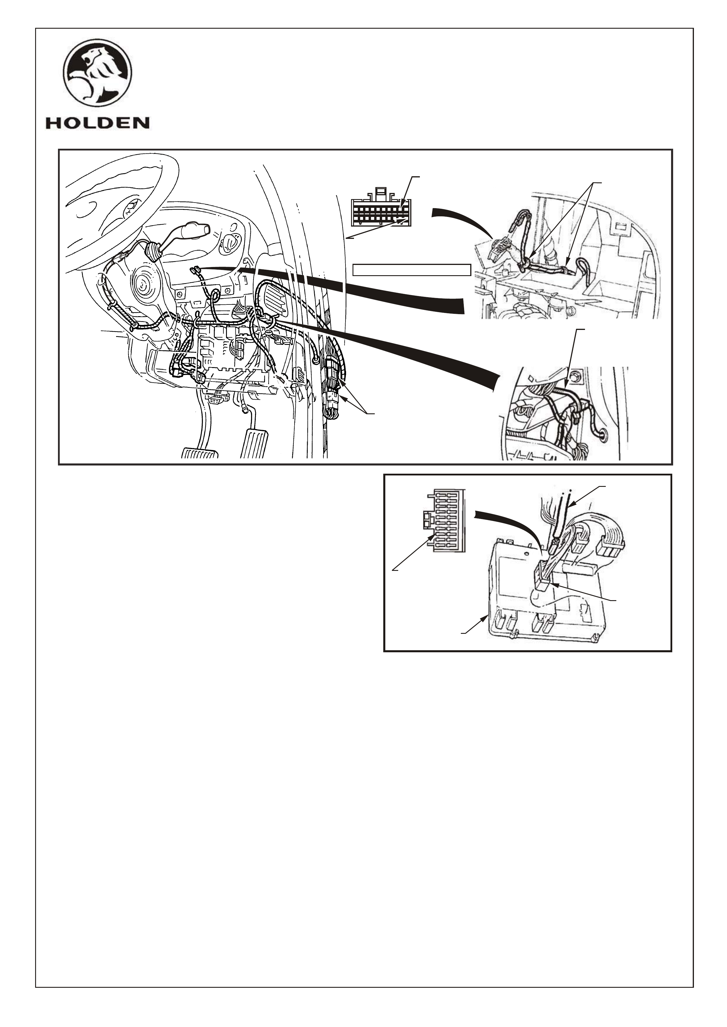
31. Route harness up through dash frame work above
fuse panel, refer fig. 19.
32. Route 22 pin connector and single grey wire back
through dash framework.
33. Disconnect existing 22 pin connectors and bridge
patch harness 22 pin connectors between, refer fig. 19.
34. Insert grey wire into BCM connector YB164
terminal cavity 8 (circuit 83), refer fig. 20.
NOTE: Terminal will click when fully seated in connector housing.
35. Route white and yellow/red wires over steering column bracket, back through hole in panel and alongside
harness to instrument cluster connector.
36. Insert white wire into connector YB66 terminal cavity 2, refer fig. 19.
37. Insert yellow/red wire into connector YB66 terminal cavity 11, refer fig. 19.
NOTE: Some vehicles come fitted with a yellow/red wire in cavity 11. Remove terminal from this cavity,
insulate and tape back.
38. Fasten patch harness to instrument cluster harness using two tie straps.
39. Reconnect connector to instrument cluster and reinstall instrument cluster with 2 screws.
40. Route remaining harness branch between fuse panel frame and fuse panel wiring, refer fig. 19.
41. Route harness on top of brake switch, above steering column.
1 11
FIGURE 20
10 20
YB164
BCM
GREY WIRE
FROM PATCH
HARNESS
INSERT GREY
WIRE FROM
PATCH HARNESS
INTO CAVITY 8.
10
20
1
11
INSTRUMENT CLUSTER
CONNECTOR
YB66 INSERT WHITE WIRE
FROM PATCH HARNESS
INTO CAVITY 2
TIE STRAP
NINE PIN
CONNECTORS
TO FORMER
INSERT YELLOW/RED
WIRE FROM PATCH
HARNESS INTO CAVITY 11
REFER TO NOTE, STEP #37
22 PIN CONNECTORS
FIGURE 19
TIE STRAPS
COPYRIGHT
Page 7 of 13
G527V8
HOLDEN SERVICE PARTS OPERATIONS
Reproduction in whole or part
prohibited without written approval
Division of HOLDEN Ltd ACN 006 893 232
FD1026
19OC01
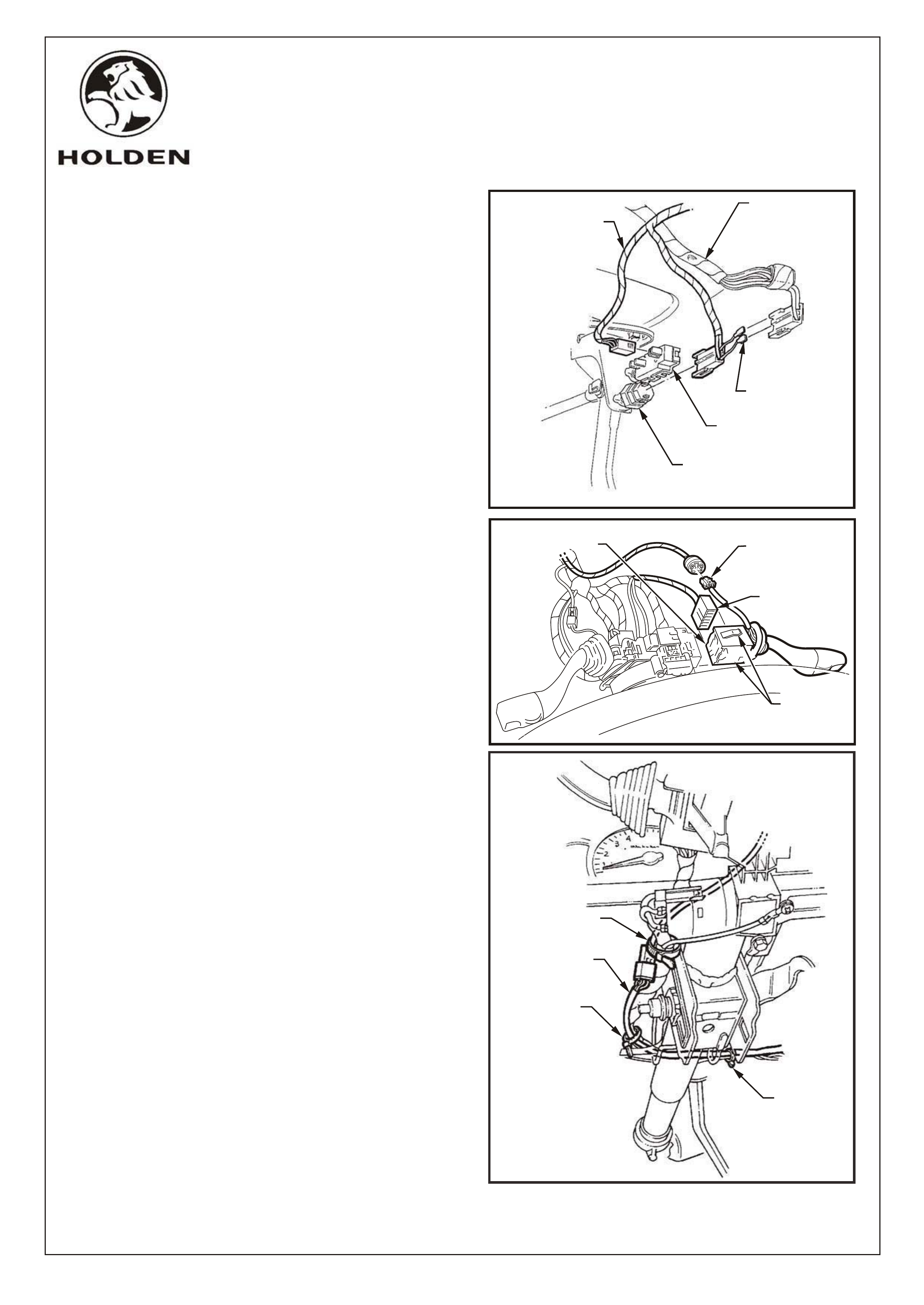
42. Disconnect brake switch connector from brake
switch, refer fig. 21.
43. Connect patch harness brake switch connector to
brake switch, refer fig. 21.
44. Insert blade terminals into vehicle brake switch
connector (ensure correct wire colors are matched).
45. Insulate blade terminals into connector housing with
electrical tape, refer fig. 21.
46. Fit clip from cruise control package to brake pedal
and adjust.
47. Fit cruise control release switch and attach
connector from patch harness, refer fig. 21.
NOTE: For MANUAL TRANSMISSION vehicles
also refer to page 12 of these instructions for
additional procedures.
48. Route patch harness up alongside steering
column wiring harness to stalk switches,
refer fig. 22.
49. Disconnect RH indicator switch connector, remove
indicator stalk and replace with cruise control/
indicator stalk from cruise control package, refer
fig. 22.
50. Connect patch harness connector to stalk switch,
refer fig. 22.
51. Secure patch harness from fuse panel to stalk
switch with supplied tie straps, refer fig. 23.
FIGURE 23
CRUISE CONTROL
PATCH HARNESS
TIE STRAP
TIE STRAP
TIE STRAP
COPYRIGHT
Page 8 of 13
G527V8
HOLDEN SERVICE PARTS OPERATIONS
Reproduction in whole or part
prohibited without written approval
Division of HOLDEN Ltd ACN 006 893 232
CRUISE CONTROL
PATCH HARNESS
EXISTING
WIRING
HARNESS
BLADE
TERMINALS
CRUISE CONTROL
RELEASE SWITCH
BRAKE
SWITCH
FIGURE 21
FIGURE 22
RH INDICATOR
STALK ASSEMBLY
RH INDICATOR
SWITCH
CONNECTOR
CRUISE CONTROL
STALK
CONNECTOR
SWITCH
RETAINING
TANGS
FD1026
19OC01
52. Bridge 2 patch harness connectors between the most inboard of the 3 engine and main wiring harness connector
pairs on former end cap, refer fig. 24.
53. Cover main wiring harness/patch harness connector with self adhesive foam (supplied in package).
54. Reinstall 3 connector pairs to former end cap.
55. Route foam covered section of harness behind former and route stepper motor connector lead beneath former to
stepper motor mounting location, refer fig. 24.
56. Route earth lead between stepper motor bracket and inner fender, to existing body earth stud. Attach cruise
control earth terminal to body earth stud, refer fig. 24.
IMPORTANT: Steps 56 to 59 apply only to vehicles which have cruise control wiring incorporated in the existing
vehicle wiring as determined by the presence of an existing stepper motor connector, refer fig. 4.
59. Holding the brake pedal in it's depressed position, install
switch into tubular clip. Push switch forward until the switch
body locates in the clip.
NOTE: Audible 'clicks' will be heard as the threaded
portion of switch assembly is pushed into the tubular clip
toward the brake pedal. Pull brake pedal fully against stop
until audible 'click' sounds can no longer be heard. (Switch
assembly is pushed back out from the clip to provide correct
switch position adjustment). Depress the brake pedal again
and repeat above procedure to ensure that the switch
adjustment is correct (no 'click' sounds).
57. Fit clip from cruise control package to mounting hole of the brake pedal support, refer fig. 25.
58. Untape connector from wiring harness and connect to cruise control release switch.
COPYRIGHT
Page 9 of 13
HOLDEN SERVICE PARTS OPERATIONS
Reproduction in whole or part
prohibited without written approval
Division of HOLDEN Ltd ACN 006 893 232
FIGURE 25
CLIP
ATTACH
CONNECTOR
TO CRUISE
CONTROL
RELEASE
SWITCH
BRAKE
PEDAL
CRUISE CONTROL
RELEASE SWITCH
G527V8
FIGURE 24
MAIN WIRING
HARNESS
CONNECTORS
CONNECT EARTH TERMINAL
TO EXISTING EARTH STUD
TIE STRAP
(2 PLACES)
CRUISE CONTROL
STEPPER MOTOR
CONNECTOR
FD1026
19OC01
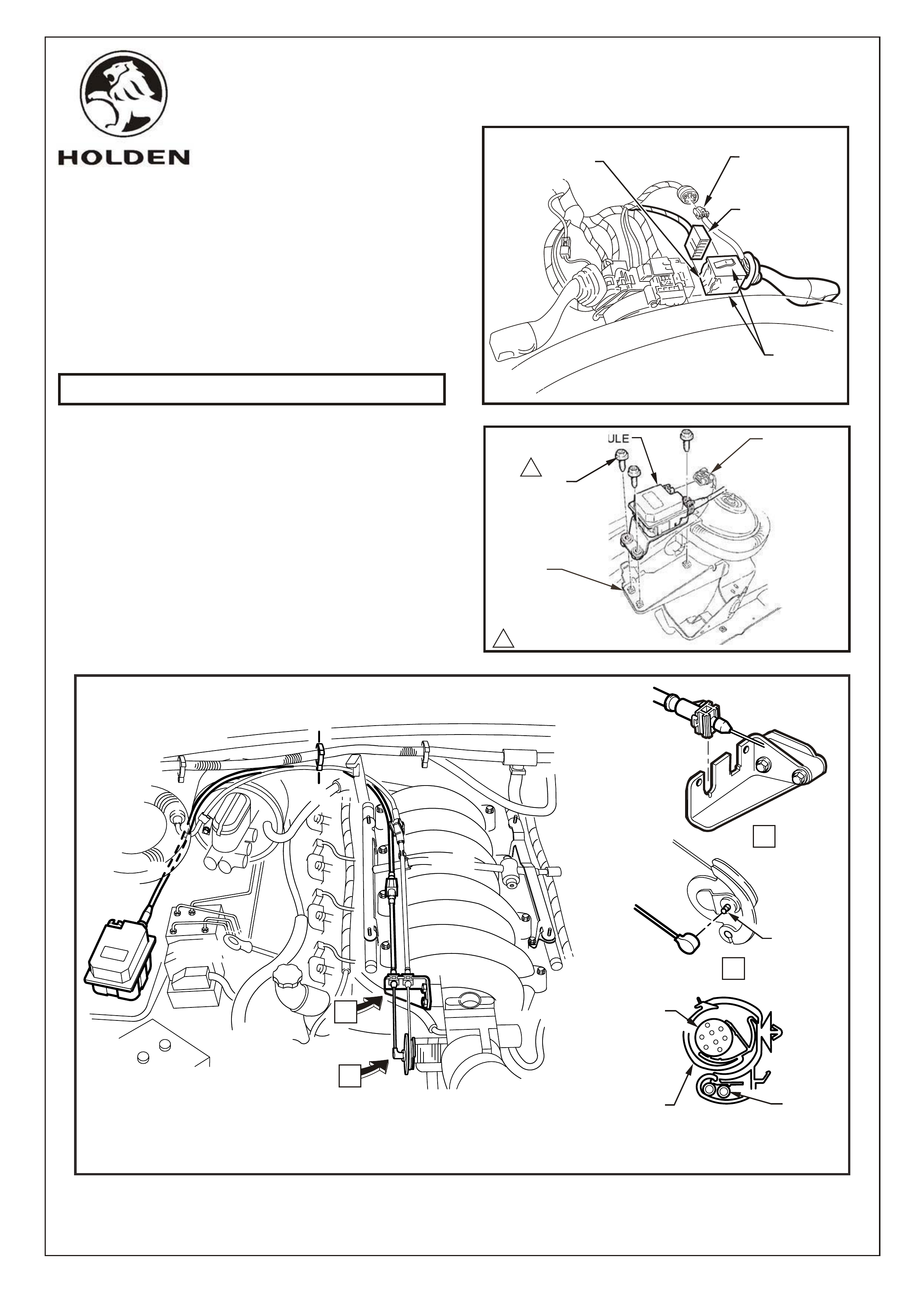
60. Disconnect RH indicator switch connector, remove
indicator stalk and replace with cruise
control/indicator stalk from cruise control package,
refer Fig 26.
NOTE: Step 61 onwards applies to all vehicles.
61. Install stepper motor to mounting bracket using 3
screws supplied and tighten (2 - 5Nm), refer fig. 27.
62. Attach connector from patch harness or existing
harness to stepper motor, refer fig.27.
63. Attach cable to rear of stepper motor, route cable
below former and drape over brake booster then
attach to engine harness retention clip on edge of
firewall, refer fig. 28.
64. Route cable alongside throttle cable and attach to
throttle bracket, refer fig. 28, View A.
65. Connect cable end to the stud on the throttle valve
lever, refer fig. 28, View B.
COPYRIGHT
Page 10 of 13
HOLDEN SERVICE PARTS OPERATIONS
Reproduction in whole or part
prohibited without written approval
Division of HOLDEN Ltd ACN 006 893 232
G527V8
CONTROL MODULE
1
SCREW
(3 PLACES)
1
2 - 5Nm
WIRING
HARNESS
CONNECTOR
ABS/CRUISE
CONTROL
MODULE
MOUNTING
BRACKET
FIGURE 27
RH INDICATOR
STALK ASSEMBLY
RH INDICATOR
SWITCH
CONNECTOR
CRUISE CONTROL
STALK
CONNECTOR
SWITCH
RETAINING
TANGS
FIGURE 26
FIGURE 28
A-A
A
A
THROTTLE
STUD
CRUISE
CONTROL
CABLE
HARNESS
RETENTION CLIP
POWER-
TRAIN
WIRING
HARNESS
A
A
B
B
FD1026
19OC01
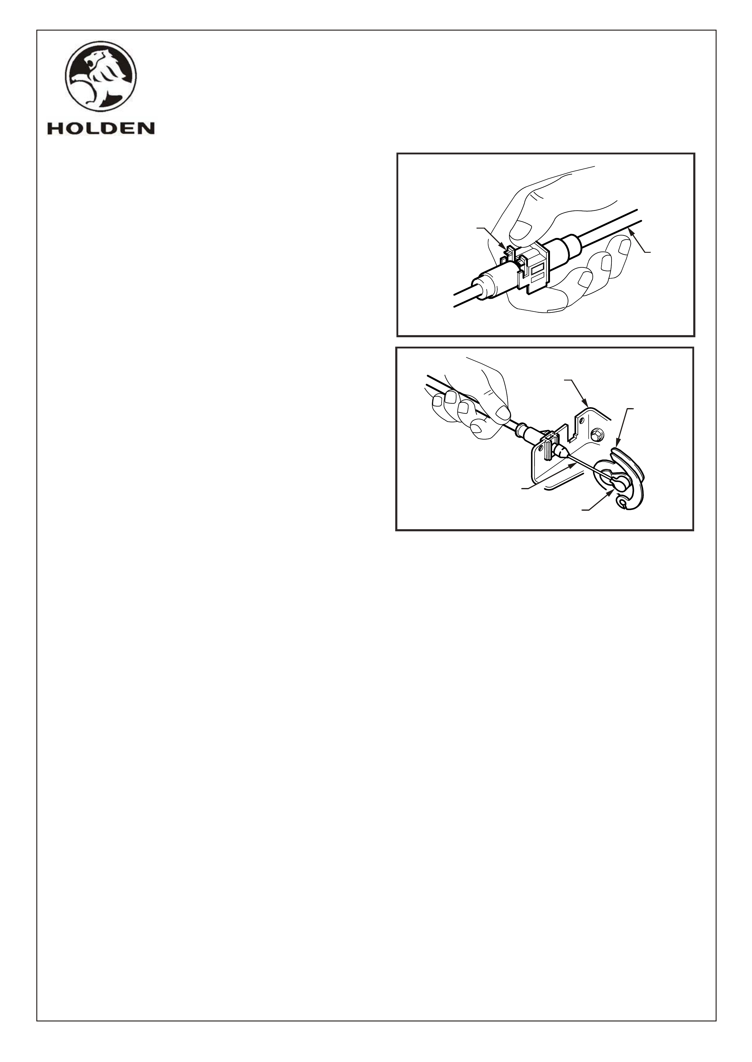
66. Adjust cable by unlocking the adjustment locking
lever, refer fig. 29.
67. Ensure throttle is closed and slide the outer cable to
achieve slack in the inner cable, refer fig. 30. Lock
the adjustment locking lever.
68. Refit strut tower former.
69. Refit relay box cover.
70. Refit the engine dress cover (four nuts).
VX Series ll Service Information
Package (SIP).
71. Refit steering wheel covers (1 screw).
72. Refit instrument facia (9 screws).
73. Refit 2 ventilation ducts (1 screw each duct).
74. Refit diagnostics connector (2 screws).
75. Refit fuse panel lower metal cover (4 screws).
76. Refit BCM.
77. Refit instrument end cap (3 screws).
78. Refit RHS inner rocker panel cover (4 TORX head
screws).
79. Refit RHS rocker panel cover insert, (snap fit).
80. Refit shroud lower trim assembly (2 screws), be
sure aligning pin at lower front of trim engages in
retainer on sheet metal.
81. Close RHS lower cover panel.
82. Re-connect the battery negative lead.
83. Reinstate the audio system by entering the security
code, refer owners manual.
84. Place fitting instructions in the glove box of vehicle.
NOTE: After installation, check operation of cruise
control, (including lamps in instrument panel) in
accordance with Section 12C, Instruments,
Wiper/Washers & Horn in
Any problems may be corrected using
this section of the SIP.
COPYRIGHT
Page 11 of 13
G527V8
HOLDEN SERVICE PARTS OPERATIONS
Reproduction in whole or part
prohibited without written approval
Division of HOLDEN Ltd ACN 006 893 232
FIGURE 30
FIGURE 29
OUTER
CABLE
ADJUSTMENT
LOCKING LEVER
THROTTLE
BRACKET
THROTTLE
VALV E
LEVER
THROTTLE
STUD
INNER
CABLE
FD1026
19OC01
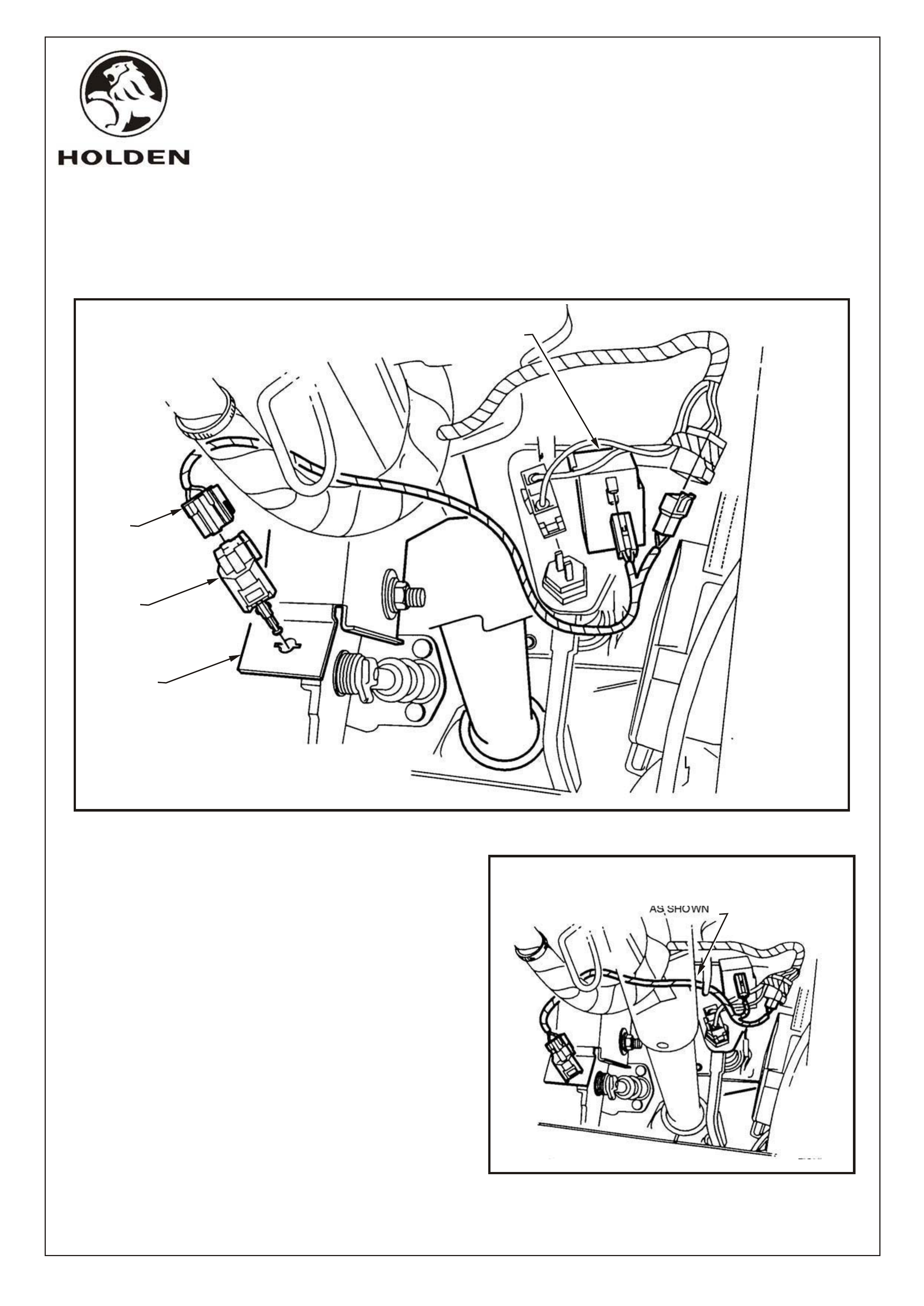
1. Adjust steering column to upper position.
2. While depressing the clutch pedal, install clutch
switch, refer fig. 31.
3. Rotate switch 90 degrees to secure position.
4. Fit the patch harness to the clutch switch,
refer fig. 31.
5. Route the patch harness over the main wiring harness
and steering column, refer fig. 32.
6. Fit the patch harness connectors to the cruise control
release switch and main wiring harness connector,
refer fig. 31.
FITTING INSTRUCTIONS FOR VX SERIES II
CRUISE CONTROL PACKAGE, MANUAL TRANSMISSION
CLUTCH SWITCH (92077936) AND PATCH HARNESS (92075048)
COPYRIGHT
Page 12 of 13
G527V8
HOLDEN SERVICE PARTS OPERATIONS
Reproduction in whole or part
prohibited without written approval
Division of HOLDEN Ltd ACN 006 893 232
FIGURE 32
FIGURE 31
CRUISE CONTROL
RELEASE SWITCH
PATCH
HARNESS
CLUTCH
SWITCH
CLUTCH
PEDAL
BRACKET
PARTIAL STEERING COLUMN
SHOWN FOR CLARITY
ENSURE PATCH HARNESS
IS ROUTED OVER MAIN WIRING
HARNESS AND STEERING COLUMN
AS SHOWN
FD1026
19OC01

PART NUMBER DESCRIPTION QUANTITY
FITTING INSTRUCTIONS
VX SERIES II CRUISE CONTROL PACKAGE (92144548),
5.7L ALLOY V8
PARTS LIST
25336985 STEPPER MOTOR & CABLE ASSEMBLY 1
92138364 BOLT - STEPPER MOTOR TO WHEELHOUSE 3
92057293 PATCH HARNESS - ENGINE BAY 1
92066173 PATCH HARNESS - CABIN 1
92089543 SWITCH - TURN SIGNAL/CRUISE 1
09794682 SWITCH - BRAKE 1
92138622 CLIP - C/CONTROL BRAKE SWITCH MOUNT 1
7436769 STRAP - 220MM 5
SP3516 STRAP - 180MM 6
92140551 LAMP ASSEMBLY - INSTRUMENT 2
FD1026 FITTING INSTRUCTIONS BOOKLET 1
FD796 WARRANTY CARD
NOT INCLUDED IN CRUISE CONTROL PACKAGE, BUT MANDATORY TO FIT
TO VEHICLES WITH MANUAL TRANSMISSION (REFER PAGE 12):-
92077936 SWITCH - CLUTCH 1
92075048 PATCH HARNESS - CLUTCH SWITCH 1
COPYRIGHT
Page 13 of 13
G527V8
HOLDEN SERVICE PARTS OPERATIONS
Reproduction in whole or part
prohibited without written approval
Division of HOLDEN Ltd ACN 006 893 232
FD1026
19OC01