FITTING INSTRUCTIONS FOR
V2 COUPE "MONARO"
1600 kg TOW BAR PACKAGE
Part Number 92144445
COPYRIGHT
Page 1 of 10
HOLDEN SERVICE PARTS OPERATIONS
Reproduction in whole or part
prohibited without written approval
Division of HOLDEN Ltd ACN 006 893 232
FD1028
28OC02
G736
Page 2 of 10
HOLDEN SERVICE PARTS OPERATIONS
Reproduction in whole or part
prohibited without written approval
Division of HOLDEN Ltd ACN 006 893 232
1,0 ~ 3,0 Nm1
1600kg TOW BAR FITTING INSTRUCTIONS
REAR BUMPER FASCIA, SUPPORT BEAM & BRACKETS REMOVAL
TOOLS REQUIRED
Allen Key - 6.0 mm, Screw Driver - Philips Head & Flat Bladed, Sockets - 10mm, 17mm, 19mm, Twist Drill - 3mm,
8mm, 10mm & 12mm, Power Drill, Saw, Knife, Vacuum Cleaner, Grease, Marker Pen, Scriber.
Open the rear compartment lid, lift up the floor carpet and remove the spare wheel.
Gently peel the rear compartment weatherstrip away from the opening flange to enable access to the four
bumper fascia scrivets.
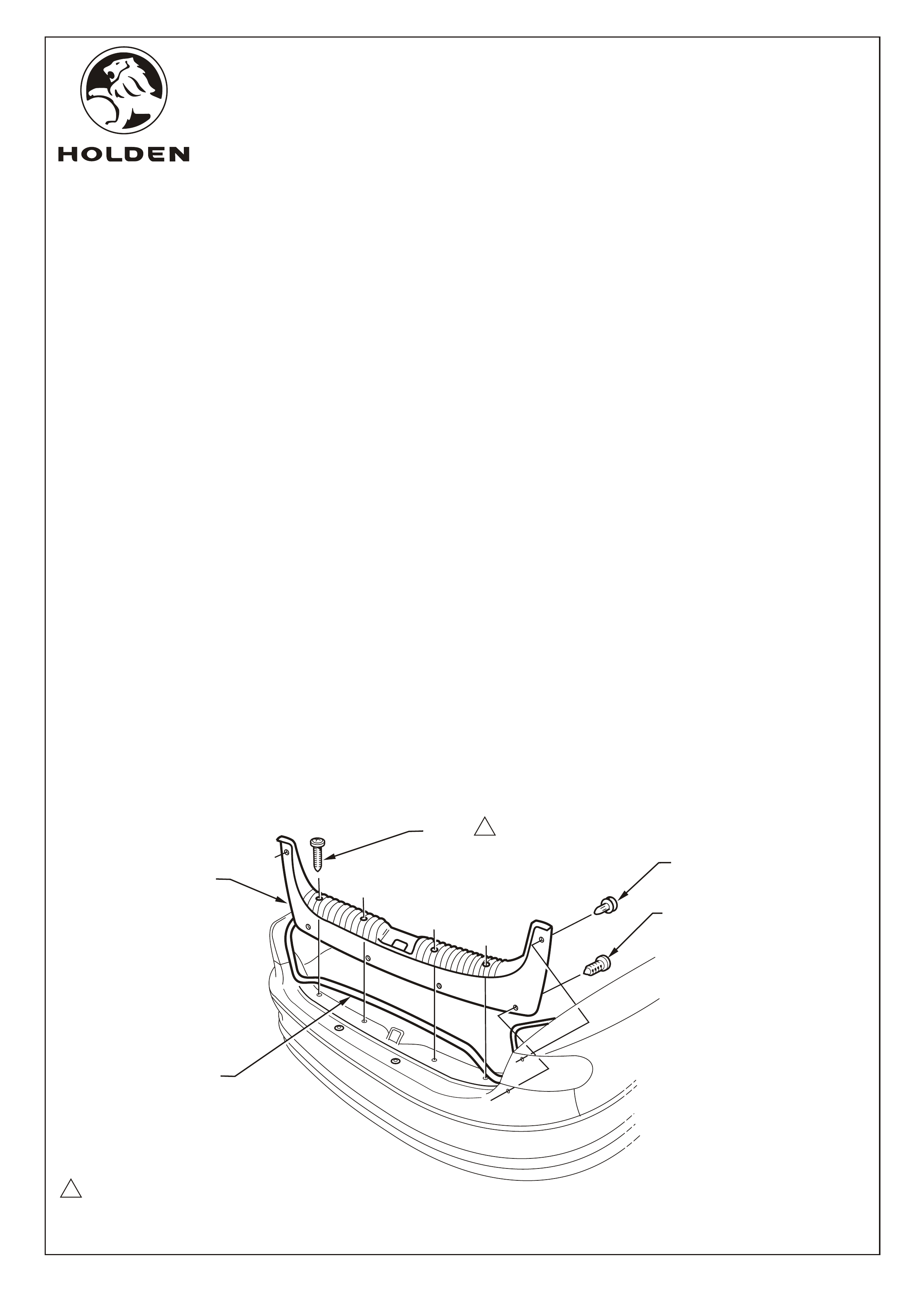
Unscrew or prise out all of the fasteners retaining the rear compartment crossmember cover and remove the
cover. Refer View.
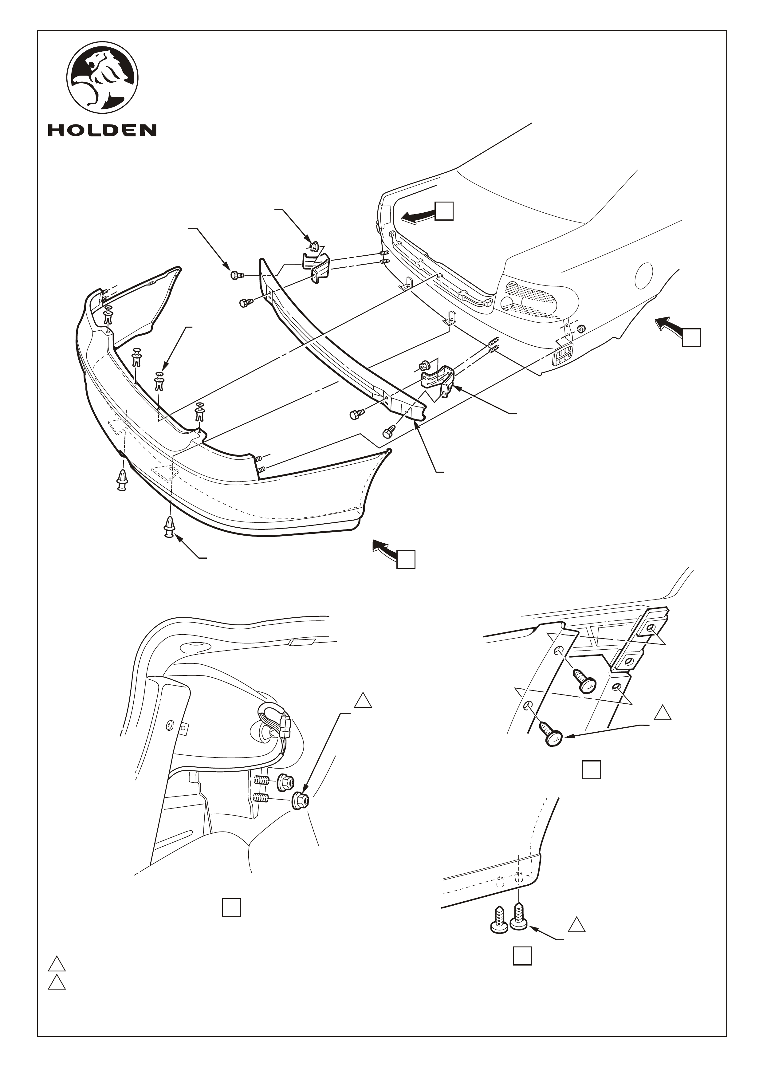
Fold the side carpet trims back from the rear corners of the rear compartment and remove the nuts (2 places
each side) securing the bumper fascia to the body. Refer View A, Page 3.
Remove the 4 scrivets on the upper edge and the 2 scrivets on the lower edge of the fascia. Refer View, Page 3.
Remove the screws, each side, fascia to the rear edge of the wheelhouse.
Refer Views B and C, Page 3.
With the fascia supported, pull the fascia sides outward disconnecting the side supports. Slide the fascia
rearwards and remove. Refer View Page 3.
Remove the bolts ( each side) securing the bumper support beam to the brackets, discard the
beam & bolts. Refer View Page 3.
Remove the nuts ( each side) securing the bumper support beam brackets to the vehicle, 2 places.
Remove the brackets and discard. Refer View Page 3. Retain the nuts for re-use.
4 places securing the
2 places
2 places
1.
2.
3.
4.
5.
6.
7.
8.
9.
1
SCREW
(4 PLACES)
SCRIVET
(2 PLACES)
WEATHERSTRIP
CROSSMEMBER
COVER
TRIM CLIP
(4 PLACES)
COPYRIGHT
G736
FD1028
28OC02
NOTE: BEFORE BEGINNING INSTALLATION CHECK VEHICLE TAG No. (Refer Page 6).
1.0 ~ 3.0 Nm
6.0 ~ 9.0 Nm
2
1
COPYRIGHT
Page 3 of 10
HOLDEN SERVICE PARTS OPERATIONS
Reproduction in whole or part
prohibited without written approval
Division of HOLDEN Ltd ACN 006 893 232
SCRIVET
(4 PLACES)
BUMPER SUPPORT
MOUNTING BRACKET
& DISCARD
REAR BUMPER
SUPPORT BEAM
& DISCARD
SCRIVET
(2 PLACES)
BOLT
(2 PLACES
R & L SIDE)
& DISCARD
NUT
(2 PLACES
R & L SIDE)
& RETAIN
2
A
B
C
VIEW B
SCREW
(2 PLACES
R & L SIDE)
VIEW A
NUT
(2 PLACES
R & L SIDE)
1
VIEW C
SCREW
(2 PLACES R & L SIDE)
1
G736
FD1028
28OC02
COPYRIGHT
Page 4 of 10
Reproduction in whole or part
prohibited without written approval
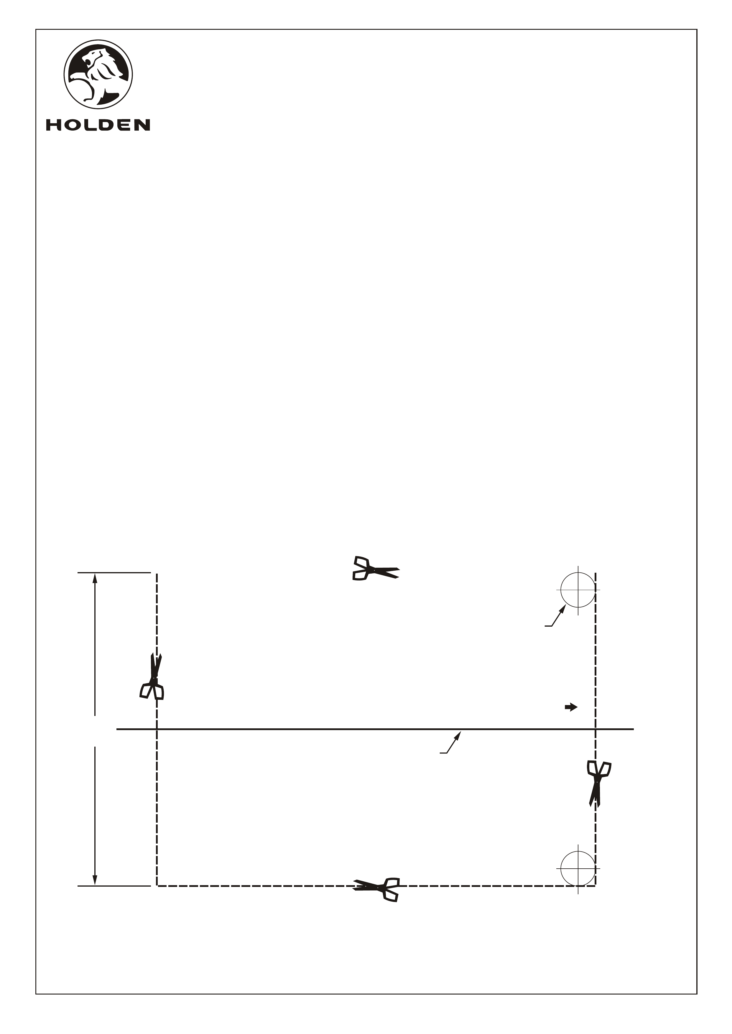
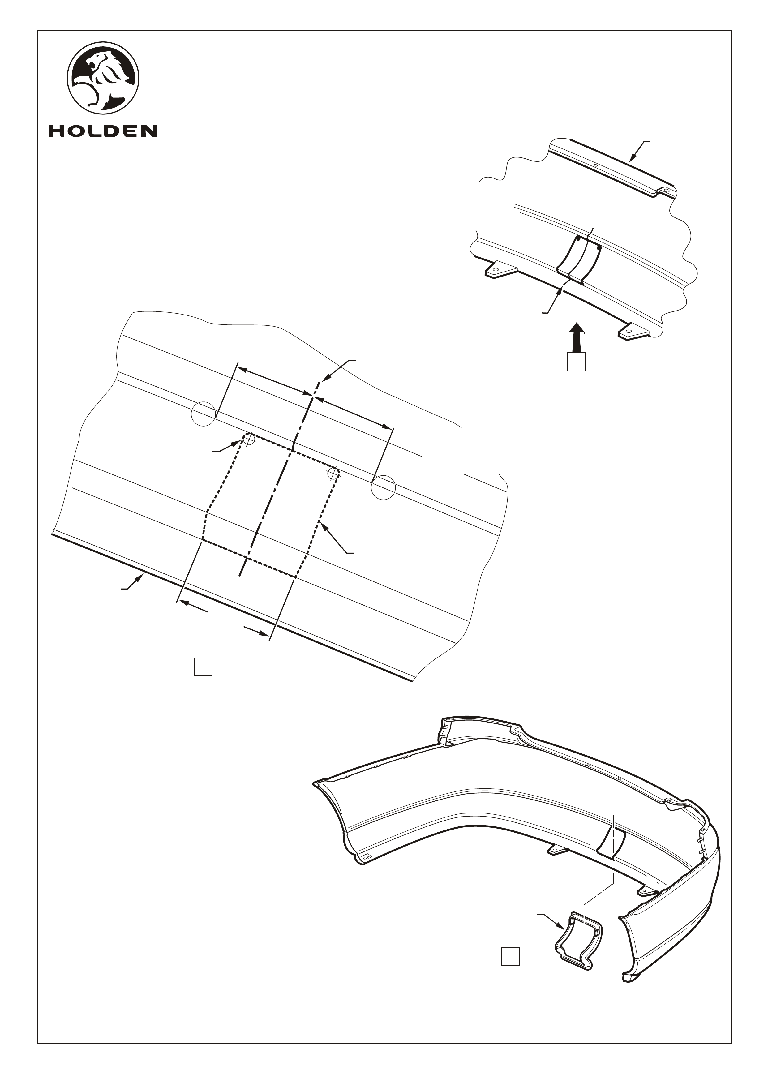
Before fascia refit, the tow bar tongue hole must be cut in the fascia
Cut out the template below, taking care to follow the perimeter line.
NOTE: The template must be 90 mm wide.
For vehicles without an embossed centre reference line, measure between the moulding injection marks
and scribe a centreline on the rear side of the fascia. Refer View A, Page 5.
Place the template on the rear side of the fascia and align the template centreline with the fascia centreline.
Refer View, Page 5.
Carefully mark the perimeter of the template on the fascia and scribe the pilot hole centre point.
Refer View, Page 5.
Drill 3.0mm dia. hole at each scribed centre point on the inside surface of the bumper fascia. Enlarge the holes
to 10.0mm. Refer View A, Page 5.
IMPORTANT: Do not drill outside the perimeter line as the surround will not cover this area.
Cut along the perimeter with a small saw or serrated knife, using care not to deviate outside the lines.
Refer View A, Page 5.
NOTE: The opening width must not exceed 90 mm.
Clean up the opening and install the tow bar surround into the fascia. Refer View B, Page 5.
10.
11.
12.
13.
14.
15.
16.
17.
HOLDEN SERVICE PARTS OPERATIONS
Division of HOLDEN Ltd ACN 006 893 232
DRILL 3.0 mm PILOT HOLES
IN FASCIA, THEN ENLARGE
TO 10.0 mm, 2 PLACES
UP
ALIGN CENTRE LINE WITH CENTRE
LINE ON FASCIA. TRANSPOSE
PERIMETER LINE TO FASCIA AND
CUT OUT TO SUIT SURROUND TRIM
CUT AROUND PERIMETER
LINE TO FORM TEMPLATE
C
L
90 mm
(REF.)
G736
FD1028
28OC02
COPYRIGHT
Page 5 of 10
Reproduction in whole or part
prohibited without written approval
HOLDEN SERVICE PARTS OPERATIONS
Division of HOLDEN Ltd ACN 006 893 232
TOWBAR SURROUND
VIEW B
CUT ALONG TEMPLATE
PERIMETER LINE
DRILL 3mm PILOT
HOLE & ENLARGE
TO 10mm.
(2 PLACES)
90mm
(REF.)
79 mm
79 mm
VIEW A
LOWER EDGE
OF FASCIA
FOR VEHICLES WITHOUT
*
EMBOSSED CENTRELINE,
MEASURE CENTRE OF INJECTION
MARKS AND SCRIBE CENTRELINE
EMBOSSED CENTRELINE
*
MARK PERIMETER OF
TEMPLATE AND SCRIBE
CENTRE OF HOLES.
BUMPER FACIA
TEMPLATE TO ALIGN
WITH CENTRELINE.
G736
A
FD1028
28OC02

COPYRIGHT
Page 6 of 10
HOLDEN SERVICE PARTS OPERATIONS
Reproduction in whole or part
prohibited without written approval
Division of HOLDEN Ltd ACN 006 893 232
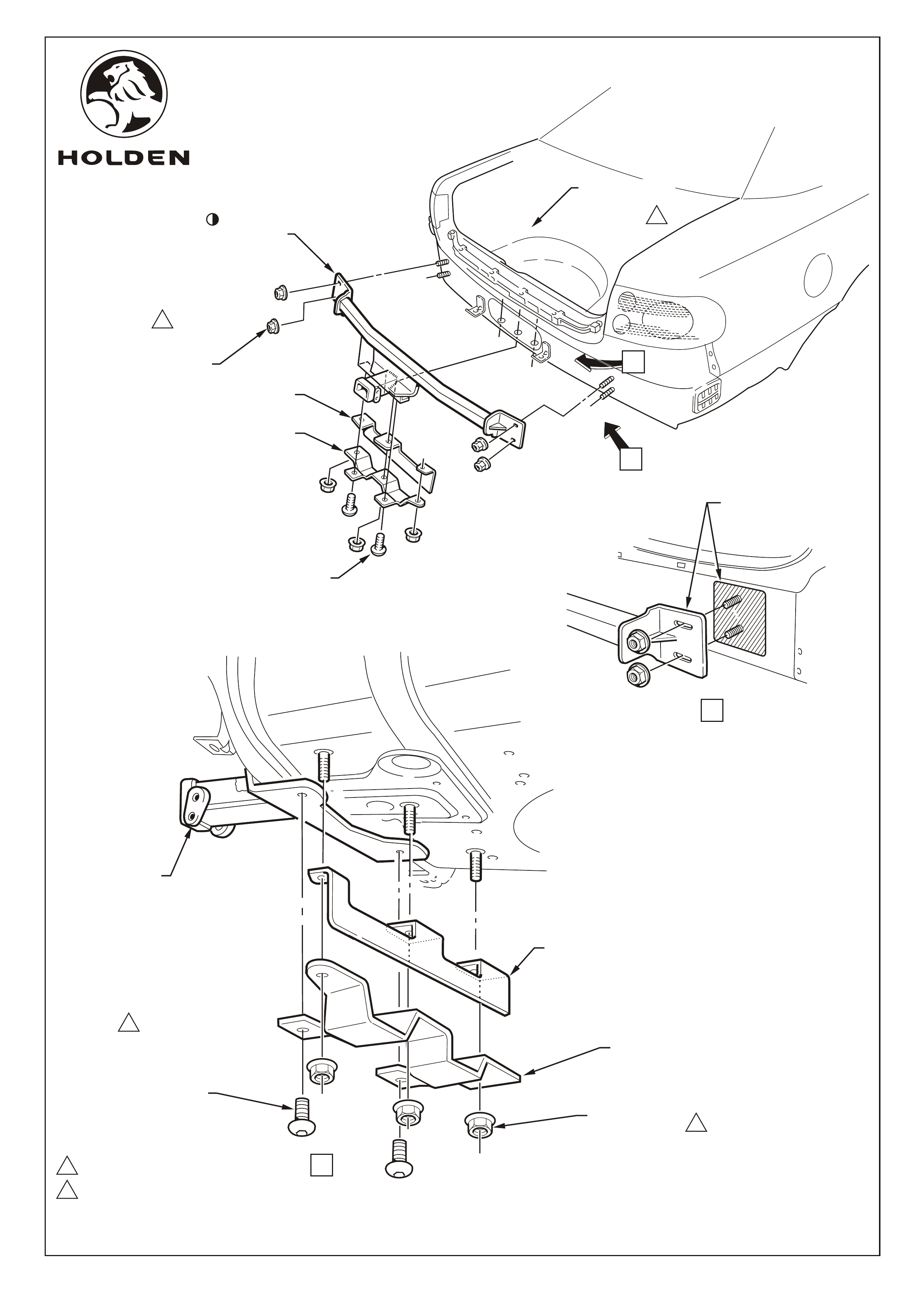
TOW BAR INSTALLATION POST TAG No. L892399
18. Scrape off any excess sealer from the body around the mounting studs where the towbar will seat. Refer
View A, Page 7.
19. Smear a thin film of grease to the bare metal exposed by removal of brackets and sealer and to the rear
face of the towbar bracket to prevent corrosion. Refer View A, Page 7.
20. Install the towbar to the four beam support studs. Centralise the towbar, fit the nuts and hand tighten,
2 places each side. Refer View A, Page 7.
21. Temporarily fit the rear bumper fascia and check that the towbar is protruding centrally through the cutout
in the fascia. Adjust the towbar as required.
22. Remove the fascia and tighten the nuts securing the tow bar to the body, 49 - 65 Nm, 2 places each side.
Refer view, Page 7.
23. Install the fuel tank shield and spare wheel well support to the spare wheel well and towbar. Fasten with the
button head socket screws (2 places), and M10 anti-rattle nuts (3 places). Tighten the spare wheel well
support nuts first, then the towbar screws to 30-40 Nm. Refer View B, Page 7.
G736
FD1028
28OC02
NOTE: Cars with TAG No.s Pre L892399 (see the last 7 characters of the VIN Number,
located behind the lower left-hand side front windscreen) require drilling holes for
fitting the spare wheel support, see separate instructions below.
Check you vehicle before starting this section.
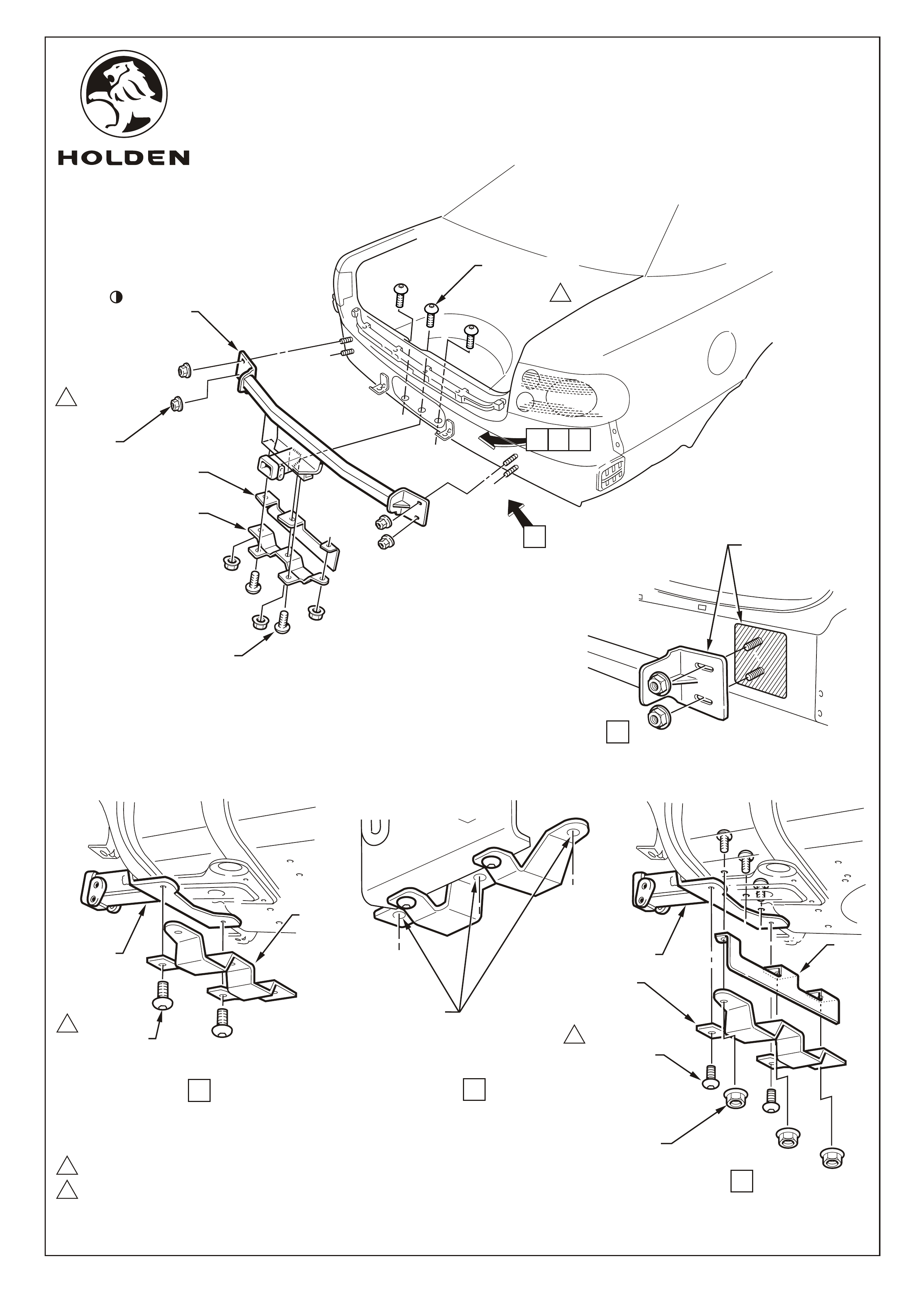
TOW BAR INSTALLATION PRE TAG No. L892399
A. Attach the spare wheel support to the towbar with the button head socket screws, 2 places
and hand tighten. Refer View B, Page 8.
B. Using the spare wheel support as a template, mark the three hole centres onto
the spare wheel well. Refer View C, Page 8.
C. Remove the support and drill three 3.0mm dia. pilot holes in the spare wheel well. Enlarge
the holes to 8mm, then to 12mm. Refer View C, Page 8.
D. Deburr the holes and remove any sealer where the support will mount onto the spare wheel well.
E. Vacuum up all swarf and debris and coat the holes with corrosion protection paint.
F. Install the fuel tank shield and spare wheel well support to the spare wheel well and towbar.
Fasten with the button head socket screws, 5 places. Tighten the spare wheel well screws
first, then the towbar screws to 30-40 Nm. Refer View D, Page 8.
THIS REPLACES INSTRUCTION 23. (ABOVE) FOR CARS PRE TAG No. L892399
1
2
30.0 ~ 40.0 Nm
COPYRIGHT
Page 7 of 10
HOLDEN SERVICE PARTS OPERATIONS
Reproduction in whole or part
prohibited without written approval
Division of HOLDEN Ltd ACN 006 893 232
SCRAPE OFF EXCESS
SEALER AND COAT
SURFACES WITH
THIN FILM OF GREASE
RH SHOWN
VIEW A
G736
FD1028
28OC02
49.0 ~ 65.0 Nm VIEW B
FUEL TANK NOT SHOWN
FOR CLARITY.
SPARE
WHEEL
WELL
SUPPORT
1
SCREW-SOCKET
BUTTON HEAD (2
PLACES). TIGHTEN
SPARE WHEEL WELL
SCREWS FIRST.
TOW BAR
ASSEMBLY
FUEL
TANK
SHIELD
NUT
(2 PLACES
R &L SIDE)
2
1
SCREW-SOCKET
BUTTON HEAD
(2 PLACES)
TOW BAR
ASSEMBLY
A
SPARE WHEEL WELL
SUPPORT ASSEMBLY
FUEL TANK SHIELD
B
SCREW-SOCKET
BUTTON HEAD
(3 PLACES)
M10 ANTI-RATTLE
NUTS 1
NUT
(2 PLACES
R &L SIDE)
2
1
1
2
SCREW-SOCKET
BUTTON HEAD
(2 PLACES)
TOW BAR
ASSEMBLY
A
30.0 ~ 40.0 Nm
49.0 ~ 65.0 Nm
VIEW C
VIEW D
SPARE WHEEL WELL
SUPPORT ASSEMBLY
FUEL TANK SHIELD
COPYRIGHT
Page 8 of 10
HOLDEN SERVICE PARTS OPERATIONS
Reproduction in whole or part
prohibited without written approval
Division of HOLDEN Ltd ACN 006 893 232
C
BD
1
VIEW B
FUEL TANK REMOVED
FOR CLARITY.
FUEL TANK REMOVED
FOR CLARITY.
SCREW-SOCKET
BUTTON HEAD (5
PLACES). TIGHTEN
SPARE WHEEL WELL
SCREWS FIRST.
TOW BAR
ASSEMBLY
1
SCREW-SOCKET
BUTTON HEAD (2 PLACES)
SPARE
WHEEL
WELL
SUPPORT
SPARE
WHEEL
WELL
SUPPORT
FUEL
TANK
SHIELD
TOW BAR
ASSEMBLY
SCREW-SOCKET
BUTTON HEAD
(3 PLACES)
SCRAPE OFF EXCESS
SEALER AND COAT
SURFACES WITH
THIN FILM OF GREASE
RH SHOWN
VIEW A
MARK THREE HOLES,
REMOVE BRACKET, DRILL
3.0 mm PILOT HOLES THEN
ENLARGE TO 8.0 mm THEN
12.0 mm.
G736
FD1028
28OC02
M10 ANTI-RATTLE
NUTS
COPYRIGHT
Page 9 of 10
Reproduction in whole or part
prohibited without written approval
Reinstall the fascia, crossmember cover, weather strip and trim, which is the reversal to the removal procedure.
NOTE: Align the studs on the fascia correctly through the holes in the body, below the tail lights.
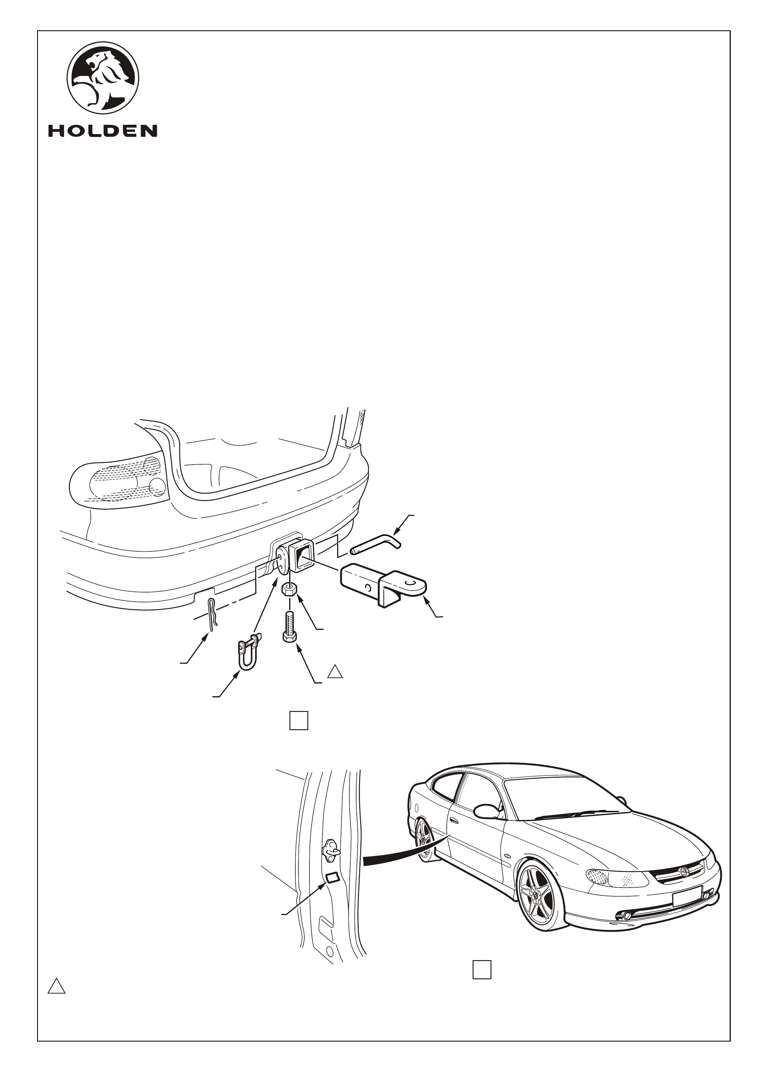
Install the towbar tongue onto the towbar assembly using the retainer pin and safety clip. Refer View A.
Install the anti-rattle bolt and nut. Tighten nut 5 - 10 Nm. Refer View A.
IMPORTANT: The anti-rattle bolt and nut must only be used when tow bar is unladen. Remove the anti-rattle
bolt and nut when the towbar is loaded.
Install the heat shield and trailer wiring harness packages as per fitting instructions included with each package.
Clean the surface of the driver's side B-pillar and apply the ADR label. Refer View B.
Once the towbar installation is complete, place the fitting instructions and warranty card in the glovebox.
24.
25.
26.
27.
28.
29.
HOLDEN SERVICE PARTS OPERATIONS
Division of HOLDEN Ltd ACN 006 893 232
SAFETY CLIP
SHACKLE
NUT M10
TOW BAR
TONGUE
ANTI -RATTLE BOLT M10 x 25
(ONLY USE WHEN UNLOADED)
1
RETAINER
PIN
VIEW A
WIPE SURFACE CLEAN
PRIOR TO APPLICATION
OF ADR LABEL
5.0 ~ 10.0 Nm
1
VIEW B
G736
FD1028
28OC02

COPYRIGHT
Page 10 of 10
HOLDEN SERVICE PARTS OPERATIONS
Reproduction in whole or part
prohibited without written approval
Division of HOLDEN Ltd ACN 006 893 232
1600kg TOW BAR KIT FOR
V2 COUPE "MONARO"
Part Number 92144445
PARTS LIST
NOT INCLUDED IN TOW BAR PACKAGE, BUT AVAILABLE SEPARATELY:
92140088 TRAILER WIRING HARNESS - FLAT 7 PIN
92140147 TRAILER WIRING HARNESS - ROUND 7 PIN (LARGE PIN)
92140148 TRAILER WIRING HARNESS - ROUND 7 PIN (SMALL PIN WITH BACKING PLATE)
92145177 PACKAGE - LOAD DISTRIBUTION HITCH (FIXED)
92140089 PACKAGE - SUPERLIFT SHOCK ABSORBERS
92140068 TOW BALL ASSEMBLY (CHROME)
92140106 TOW BALL COVER
PART NO. DESCRIPTION QUANTITY
92106900 TOW BAR MAIN ASSEMBLY 1
SCREW - SOCKET BUTTON HEAD M10 x 30 5
BOLT - ANTI-RATTLE M10 x 25 1
NUT - ANTI-RATTLE M10 4
92106902 SUPPORT ASSEMBLY - SPARE WHEEL WELL 1
92106903 SHIELD - FUEL TANK 1
92144444 SURROUND - TOWBAR 1
92077203 'D' RING SAFETY SHACKLE 1
ADR LABEL 1
FD1028 TOW BAR FITTING INSTRUCTION BOOKLET 1
FD796 WARRANTY CARD 1
92145225 PACKAGE - TOW BAR TONGUE (PAINTED) 1
92143923 PACKAGE - HEAT SHIELDS 1
- 92037805 Heat Shields - Spare Wheel Well 6
- FD974 Fitting Instruction 1
- 92143924 Heat Shield Package - Centre Bearing 1
- Bolt - Centre Bearing Heat Shield Mounting M8 2
- Washers 2
- FD1028 Fitting Instruction
G736
FD1028
28OC02