FD1053
18MR02
FITTING INSTRUCTIONS FOR
WH2 SUPER LIFT SHOCK ABSORBER PACKAGE (SEDAN)
Part No. 92145333
COPYRIGHT
Page 1 of 5
G623-1
HOLDEN SERVICE PARTS OPERATIONS
Reproduction in whole or part
prohibited without written approval
Division of HOLDEN Ltd ACN 006 893 232

G623-2
FD1053
18MA02
TOOLS REQUIRED
Power Drill, 6.0mm dia. Drill Bit
Sockets 16.0 mm, 20.0 mm, Rachet Wrench
Torque Wrench, Masking Tape
Metric Ruler, Marking Pen,
Centre Punch, De-burring Tool
Corrosion Protection Paint
Vehicle 2 Post Hoist or Trolley Jack
Vacuum Cleaner.
FITTING INSTRUCTIONS
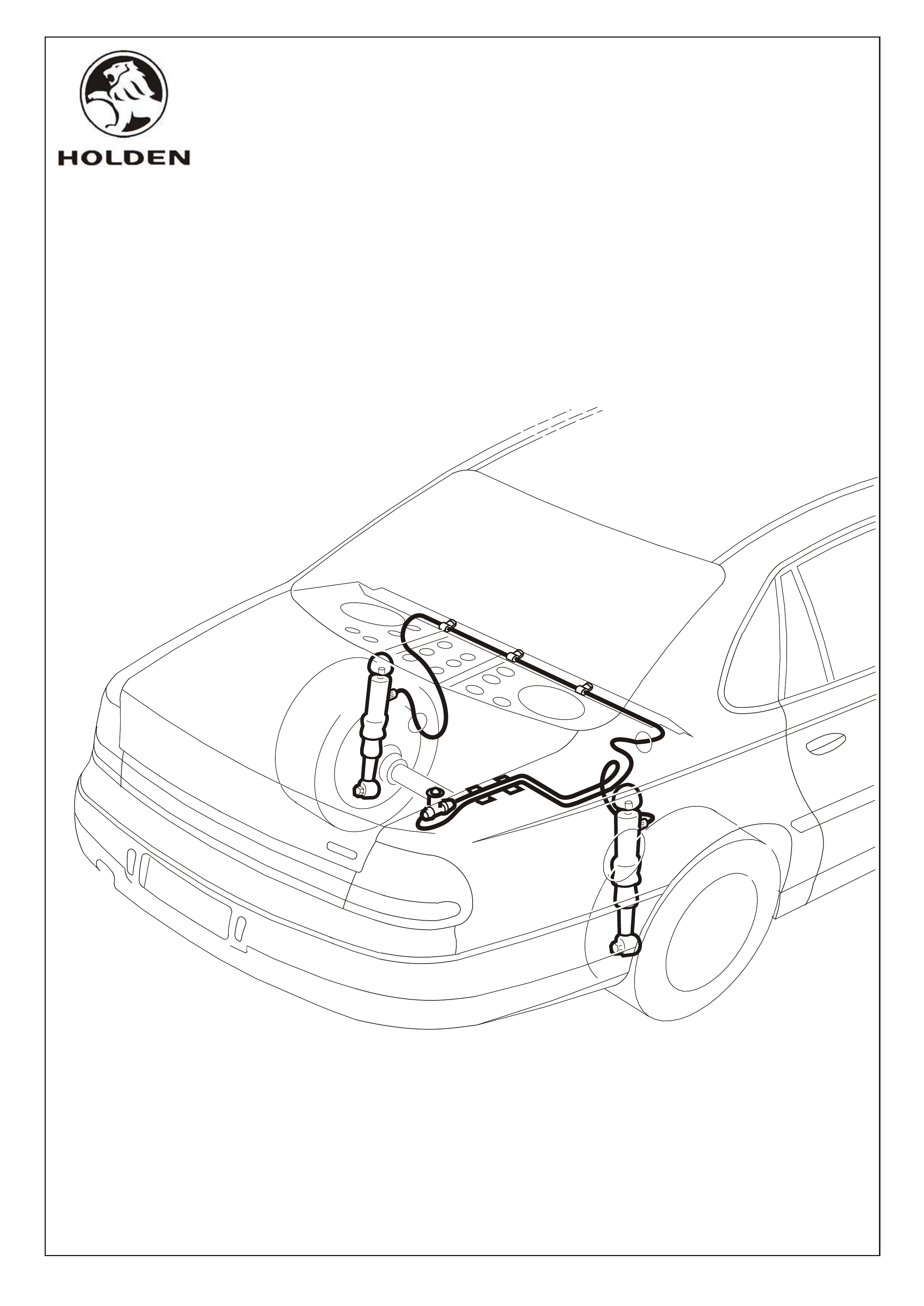
1. Remove the floor and quarter side trim from the rear compartment.
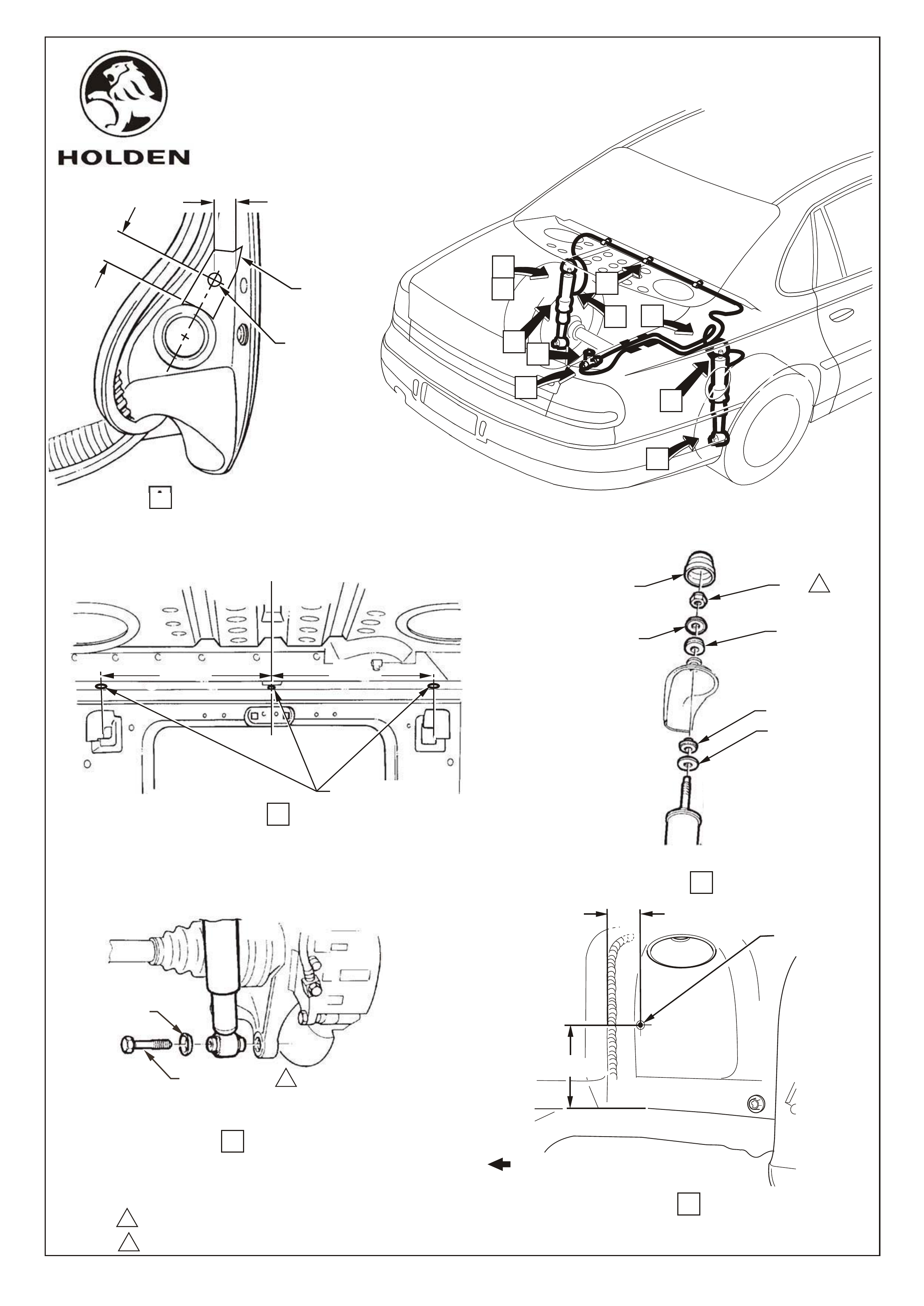
2. Apply masking tape( to aid marking and drilling) and mark out T- valve location hole on the RH rear quarter panel drip
gutter area. Refer View A, Page 3. Centre punch and drill a 8.0mm dia. hole for T-valve mounting. Remove masking
tape, debur hole and vacuum away all swarf. Coat hole with anti- corrosion primer.
5. With the shock absorbers removed and from the outside of the vehicle, mark the drilling locations on the shock absorber
turrets, as shown on View E, Page 3. Centre punch and drill a 6.0mm dia. hole, one each side. D
6. Fit both the Super Lift shock absorbers with the air line connections Facing Front of the vehicle
Torque the lower shock absorber mounting bolts to 105-125Nm.
9. Feed approximately 150mm of air line through the grommet in the LH shock absorber turret, from the inside rear
compartment.
10. Raise the vehicle and a
11. Lower the vehicle and route the air line up through the hole in LH gusset (under rear parcel shelf) , across and through
hole in RH gusset. Refer View H, Page 4.
12. Clip the air line to parcel shelf at hole locations drilled previously (3 places). Refer View H & K, Page 4.
13. Route air line through the existing hole in the rear compartment side panel inner and along quarter panel drip gutter.
Retain with existing clips , 2 places to T-valve location as shown. Refer View K, Page 4. Cut air line to suit correct length..
14. Raise the vehicle and attach the air line to the RH shock absorber valve, using the 'O' ring and cap. Hand tighten air line
cap. Refer View G, Page 4.
17. Install airline caps and ‘O’ rings to both airlines and install onto T- valve and hand tighten.
18. Fit T- valve assembly to drilled hole in RH quarter body panel using pressure guide label, washer and nut, be sure not to
over tighten. Refer View J, Page 4..
19. Ensure air lines are free of kinks or other interference. Inflate shock absorbers to maximum pressure, 1030kPa (150psi)
and check all connections for leaks.
IMPORTANT: MINIMUM PRESSURE 100kPa (15p.s.i.)
MAXIMUM PRESSURE 1030kPa (150p.s.i.)
Do not exceed 1030 kPa (150p.s.i.) regardless of load
Extremely heavy loads will prevent the attainment of normal height with maximum air pressure.
NOTE: Units should not be inflated so as to exceed vehicle manufacturers designed standard ride height.
20. Replace all the rear compartment trim and refit the shock absorber cap cover.
21. Place fitting Instructions in the vehicles glove compartment.
3. Apply masking tape( to aid marking and drilling) and mark out as shown, 3 holes on the lower horizontal surface of the
parcel shelf panel. Refer View B, Page 3. Centre punch and drill 6.0mm dia. holes at 3 places for the air line clips. Debur
all holes and vacuum away all swarf. Coat holes with anti- corrosion primer.
4. Place the vehicle on a hoist (2 post type) or jack up the rear end. Remove the rear shock absorbers. Refer Views C & D,
Page 3.
NOTE: The road wheels will require removal if the vehicle is raised with a trolley jack.
ebur holes, vacuum
away all swarf and coat the thole with anti- corrosion primer.
7. Lower the vehicle and from the inside of the rear compartment, install the shock absorber upper bush, upper plate
and nut. Torque the upper shock absorber mounting to 12~16 Nm. Refer View C, Page 3.
8. From the inside the rear compartment, insert the grommets into the holes in the shock absorber turrets. Refer View
F, Page 4.
ttach the air line to the LH shock absorber using 'O' ring and cap. Hand tighten air line cap. Refer
View G, Page 4.
NOTE: Tape up open end of air line to prevent entry of foreign matter during routing.
15. Feed the remaining airline, approximately 150mm through grommet in RH shock absorber turret from the outside of the
wheel house. Lower the vehicle.
16. Route air line through existing hole in the rear compartment side panel inner and along quarter panel drip gutter retaining
with existing clips , 2 places to valve location as shown.Refer View K, Page 4. Cut off excess air line.
COPYRIGHT
Page 2 of 5
HOLDEN SERVICE PARTS OPERATIONS
Reproduction in whole or part
prohibited without written approval
Division of HOLDEN Ltd ACN 006 893 232
FD1053
18MR02
FRONT OF VEHICLE
COPYRIGHT
Page 3 of 5
G623-3
HOLDEN SERVICE PARTS OPERATIONS
Reproduction in whole or part
prohibited without written approval
Division of HOLDEN Ltd ACN 006 893 232
105,0 - 125,0 Nm
12,0 - 16,0 Nm
E
K
J
G
D
A
C
F
H
VIEW A
DRILL 8.0 mm
DIA HOLE
MASKING
TAPE
25.0 mm
17.0 mm
VIEW B
C
L
DRILL 6.0 DIA. HOLES
(EQUAL DISTANCE FROM
CENTER HOLE)
FOR AIR LINE CLIPS
350 mm
APPROX 350 mm
1
VIEW D
WASHER
MOUNTING BOLT 1
2
RIGHT SIDE SHOWN
CAP
COVER
UPPER
PLATE
NUT
UPPER BUSH
LOWER BUSH
LOWER PLATE
VIEW C
2
40.0 mm
100.0 mm
DRILL
6.0 mm
DIA HOLE
VIEW E
LEFT SIDE SHOWN
LEFT SIDE SHOWN
APPROX
B

FD1053
18MR02
PRESSURE
GUIDE LABEL
NUT
RUBBER WASHER
CAP
'O' RING
(2 PLACES)
AIR
LINE
'T' VALVE
AIR LINE CAP
(2 PLACES)
AIR LINE
VIEW F
GROMMET
LEFT SIDE SHOWN
VIEW J
DETAIL 'M'
(3 PLACES)
COPYRIGHT
Page 4 of 5
G623-4
HOLDEN SERVICE PARTS OPERATIONS
Reproduction in whole or part
prohibited without written approval
Division of HOLDEN Ltd ACN 006 893 232
VIEW H
LH SIDE
REFER DETAIL 'M'
EXISTING WIRING
HARNESS CLIPS
(2 PLACES)
REFER DETAIL 'M'
VIEW K
RH SIDE
J
ROUTE BEHIND
HARNESS
'O' RING
AIR LINE CAP
AIR LINE
VIEW G
LEFT SIDE SHOWN
FRONT OF VEHICLE
FD1053
18MR02
92055607 SUPER LIFT SHOCK ABSORBER ASM. 2
MOUNTING KIT - SHOCK ABSORBER,(TWO KITS PER PACKAGE)
CONSISTS OF:
11092721 NUT 1
92040086 RETAINER WASHER - UPPER 1
92040066 RUBBER CUSHION - UPPER 1
92042513 RUBBER CUSHION - LOWER 1
92040086 RETAINER WASHER - LOWER 1
KIT - AIR LINE, CONSISTS OF:
NUT 1
VALVE CAP - PLASTIC 1
WASHER - PLASTIC 1
LABEL - PRESSURE GUIDE 1
CAP - AIR LINE FITTING 4
AIR LINE - NYLON 1
GROMMET SET 1
' T' VALVE 1
'O' RING 4
INSTRUCTION SHEET('T' VALVE ASSEMBLY) 1
92056424 CLIP - AIR LINE TO BRAKE LINE 6
FD1053 FITTING INSTRUCTIONS BOOKLET 1
A. Do not adjust or tighten the tee-piece AIR VALVE. The valve may feel lose, But do not adjust or
tighten it.
The valve has been pre-assembled in the plastic tee-piece at the correct torque to ensure no air
leakage by the manufacturer, Overtightening will cause valve seal failure.
B. Do not apply side load to the plastic valve stem. Do not bend the plastic valve stem during or
after installation to your vehicle. Before drilling the hole for the tee-peice, ensure that there will be
sufficient clearance for the complete tee-peice with airline and airline nuts assembled. B ent or
deformed plastic valve stems may result in air leakage.
PART NUMBER DESCRIPTION QUANTITY
FITTING INSTRUCTIONS
WH2 SUPER LIFT SHOCK ABSORBERS PACKAGE,
SEDAN (92145333)
Parts List
Page 5 of 5
G623-5
HOLDEN SERVICE PARTS OPERATIONS
Reproduction in whole or part
prohibited without written approval
Division of HOLDEN Ltd ACN 006 893 232
COPYRIGHT
WARNING....IMPORTANT