FITTING INSTRUCTIONS FOR
VY AND WK STATESMAN/CAPRICE
REAR ASHTRAY/CIGAR LIGHTER PACKAGE
Part Number 92146210
COPYRIGHT
Page 1 of 10
G791
Reproduction in whole or part
prohibited without written approval
HOLDEN SERVICE PARTS OPERATIONS
Division of HOLDEN Ltd ACN 006 893 232
FD1067
11MA03
1
Page 2 of 10
COPYRIGHT
Reproduction in whole or part
prohibited without written approval
FITTING INSTRUCTIONS FOR
VY AND WK STATESMAN/CAPRICE
REAR ASHTRAY/CIGAR LIGHTER PACKAGE
TOOLS REQUIRED:
Special Tool KM6067, Phillips Head Screwdriver, Flat-blade
Type Screwdriver, 10mm Socket and Insulating Tape.
FITTING INSTRUCTIONS:
Disassembly Procedure
1. Disconnect the battery.
CAUTION: This may impact or damage electrical
systems in the vehicle, Body Control Module,
Entertainment System, Electric Sun Roof, etc unless
correct instructions are followed. Please contact your
Holden Retailer for further information.
NOTE: To reinstate the audio system, the security
code will be required.
For Vehicles without Navigation System, go to
Page 4, Step 10.
For vehicles with Navigation System, proceed as follows:
2. VY & WK
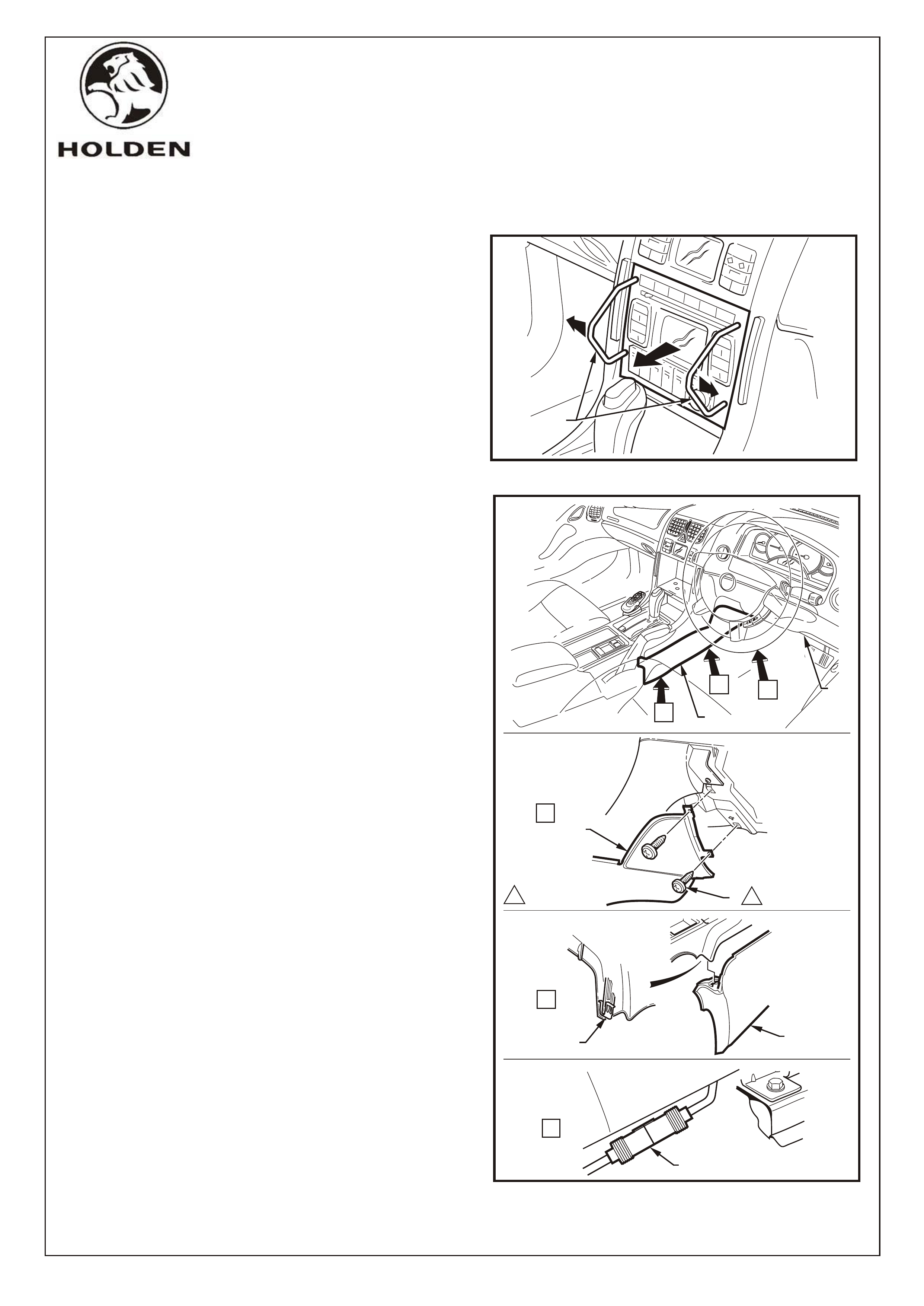
Remove the radio assembly as follows.
Refer Figure 1.
A. Insert Special Tools KM6067 (1) into the holes
on each side of the radio assembly.
B.
VY & WK
Remove the right hand side instrument panel lower
extension side trim as follows. Refer Figure 2.
A. Move the right hand front seat to its rearmost
and uppermost position.
While applying outwards pressure on the tools
(towards each outer side of the radio), pull the
radio assembly out of the radio housing.
NOTE: The wiring connectors remain attached to the
radio housing and will disconnect on the removal of
the radio.
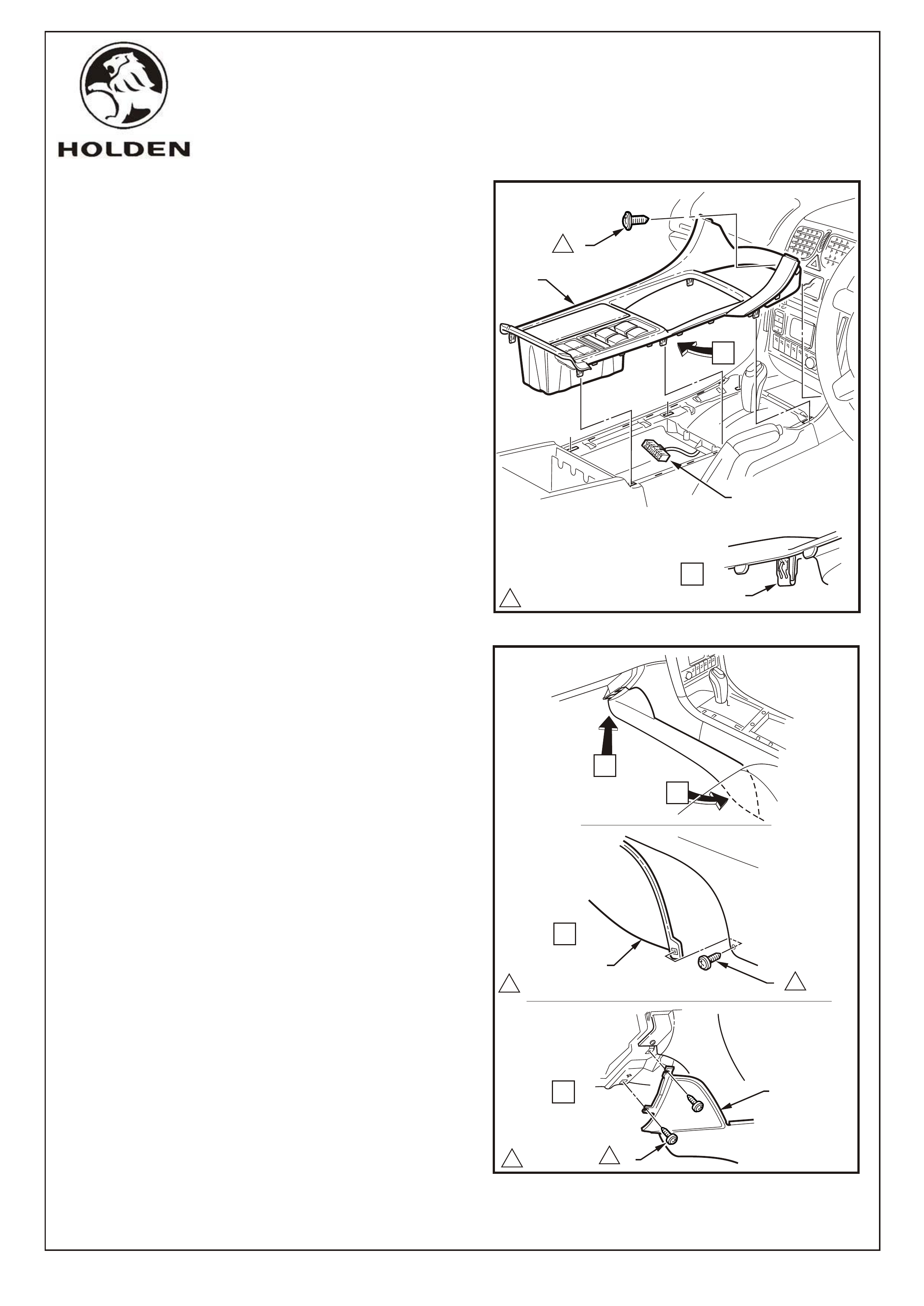
3.
B. Open the instrument panel lower trim panel (1)
and remove the two screws (2) attaching the
instrument panel lower extension side trim (3) to
the instrument panel - Refer View A.
C. Prise the rear of the trim panel (3) downward to
disengage it from the floor console retaining clip
(4) - Refer View B.
D. Remove the side trim (3).
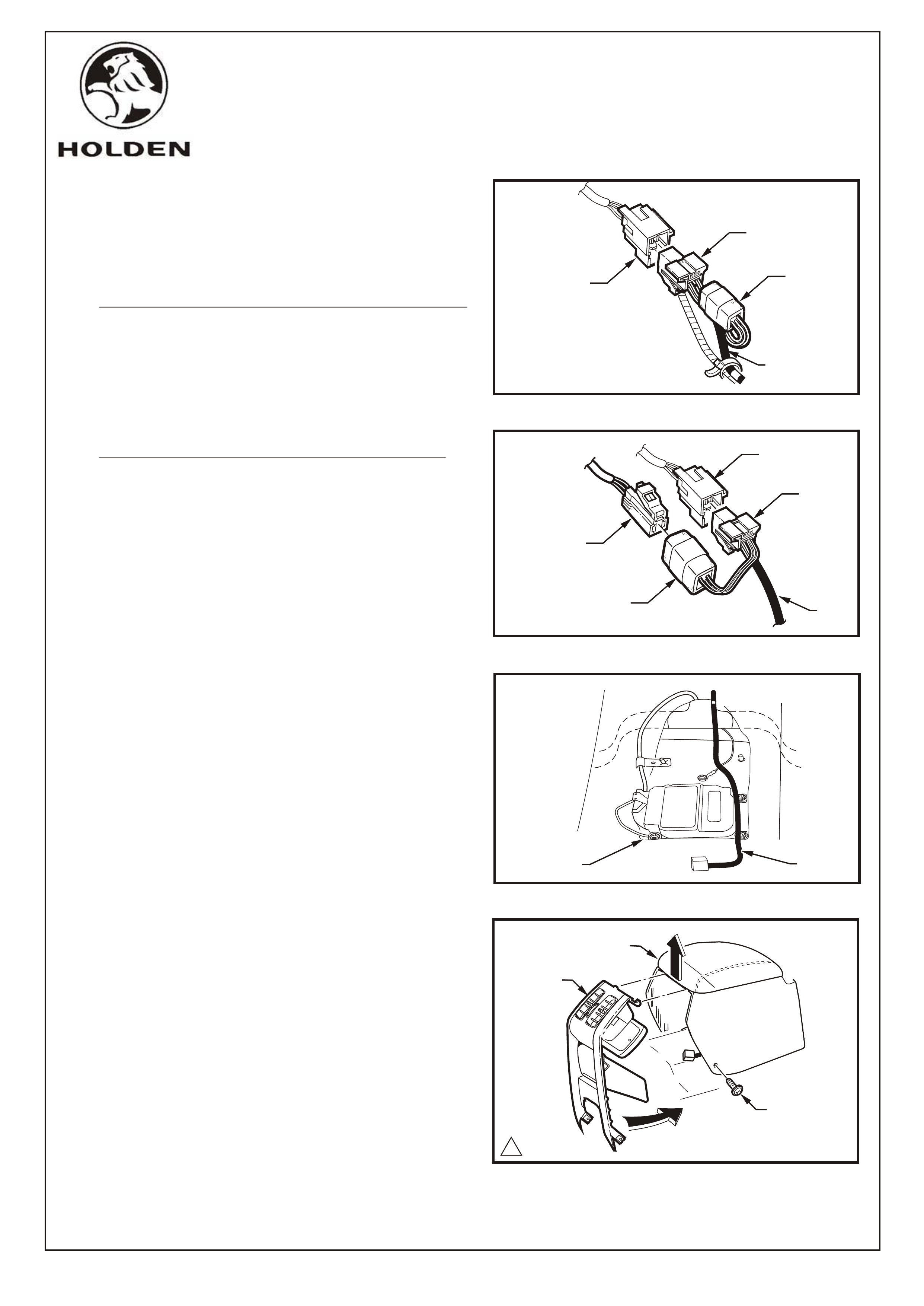
4. Disconnect the remote control harness from the
cockpit navigation wiring harness connector (5).
Refer Figure 2, View C.
FIGURE 1
HOLDEN SERVICE PARTS OPERATIONS
Division of HOLDEN Ltd ACN 006 893 232
G791
VY SHOWN
1
A
B
3
2
3
4
C
11.0 - 3.0 Nm
5
C
B3
A
VIEW
VIEW
VIEW
1
FIGURE 2
FD1067
11MA03
VY SHOWN
FITTING INSTRUCTIONS: - continued
Disassembly Procedure -continued
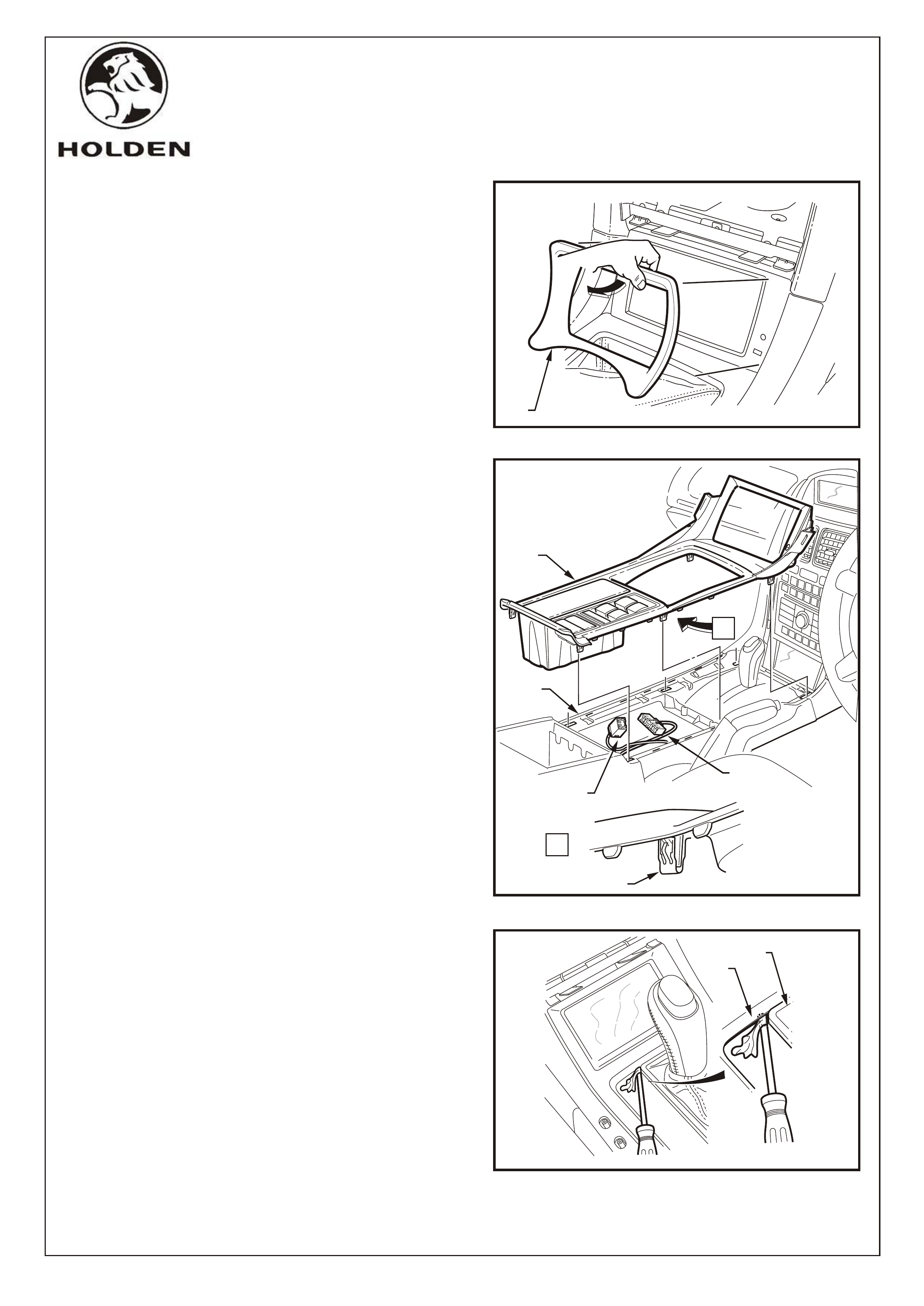
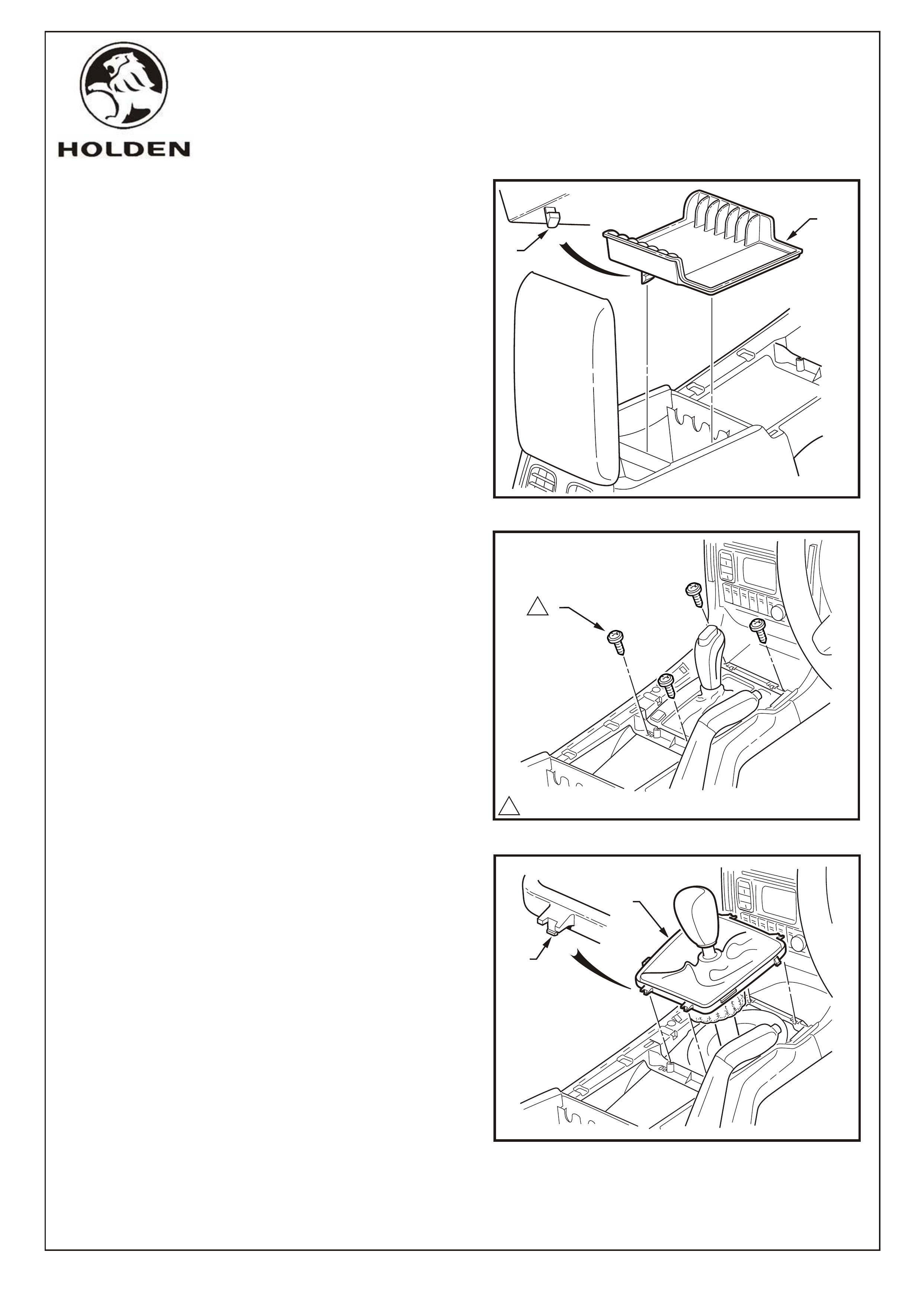
5. VY ONLY
Remove the navigation escutcheon (1) by grasping
the top edge of the escutcheon and pivoting away and
up from the navigation display. Refer to Figure 3.
6. WK ONLY
Gently prise the floor console cover assembly (1) from
the floor console (2) and unclip each of the six
fastener clips (3) at the points indicated.
Refer Figure 4.
7. WK ONLY
Disconnect the hazard warning switch connector (4)
and auxiliary switch connector (5) from underneath
the floor console cover assembly.
Refer Figure 4.
WK ONLY
NOTE: To assist removal of the floor console cover,
wedge a flat blade screwdriver with the blade
wrapped with cloth between the transmission selector
assembly applique (1) and the floor console cover (2)
as shown. This will prevent the selector assembly
applique from getting caught on the console cover
when the console cover is raised. Refer Figure 5.
FIGURE 3
WK ONLY
1VY ONLY
WK ONLY
Page 3 of 10
COPYRIGHT
Reproduction in whole or part
prohibited without written approval
HOLDEN SERVICE PARTS OPERATIONS
Division of HOLDEN Ltd ACN 006 893 232
G791
FIGURE 4
5
A
3
A
1
2
4
1
2
FIGURE 5
FD1067
11MA03
Page 4 of 10
COPYRIGHT
Reproduction in whole or part
prohibited without written approval
HOLDEN SERVICE PARTS OPERATIONS
Division of HOLDEN Ltd ACN 006 893 232
G791
FITTING INSTRUCTIONS: -continued.
Disassembly Procedure -continued
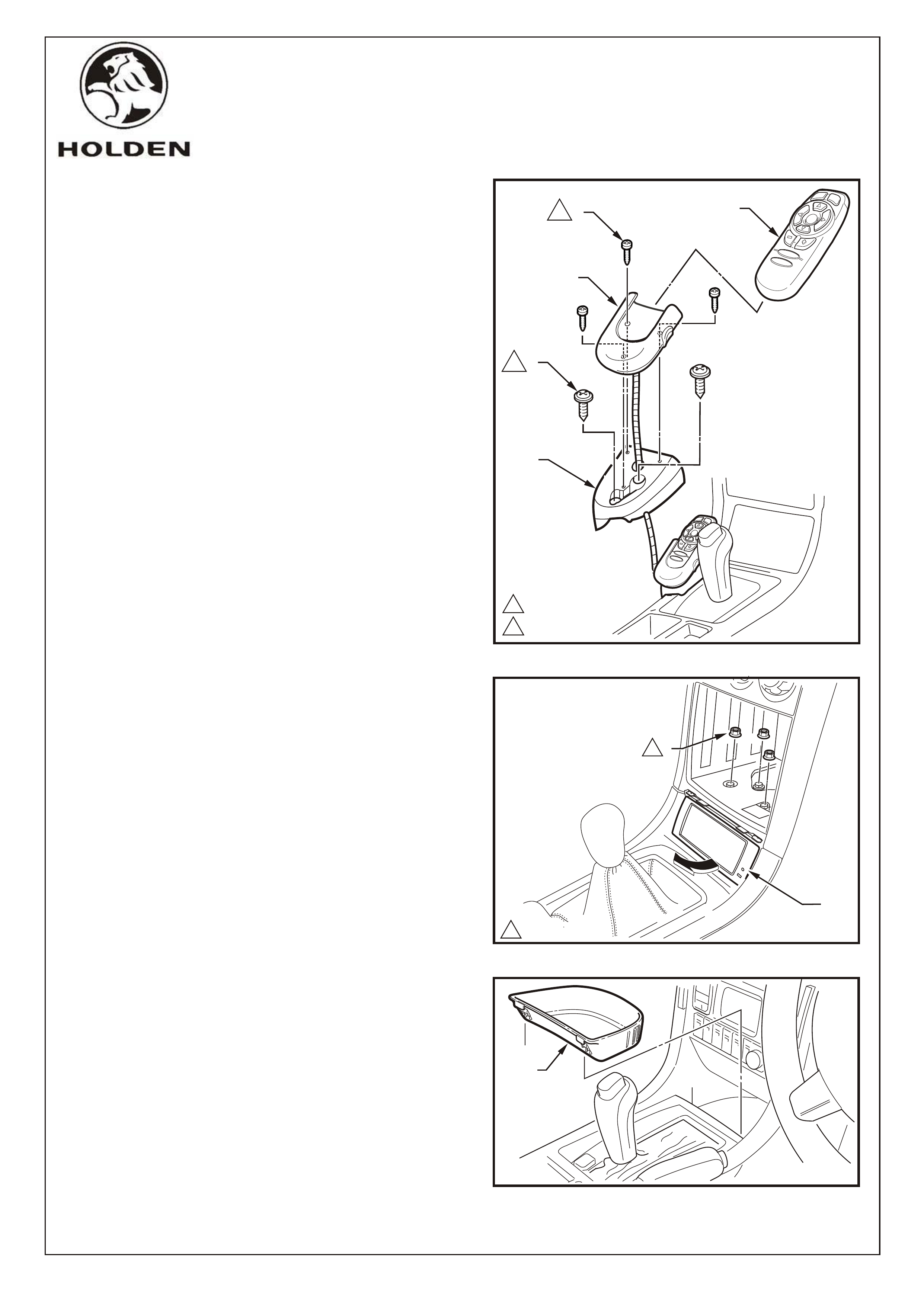
9.
Remove the navigation display assembly (1) as follows.
A. Remove the three nuts (2) securing the
navigation display mounting bracket to the radio
housing. Refer Figure 7.
B. Slowly pivot the lower part of the Navigation
display assembly up and to the rear of the
vehicle.
C. Disconnect the wiring harness connector from
the navigation display unit.
D. Remove the navigation display assembly.
8. VY & WK
Remove the remote control, cradle and presenter as
follows. Refer Figure 6.
A. Remove the remote control (1) from the cradle
(2).
B. Remove the three screws (3), lift the cradle and
place to one side.
IMPORTANT: Do not place undue stress on the
remote control cable wiring harness.
C. Remove the two screws (4) and lift the
presenter.
NOTE: It is not necessary to completely remove the
presenter/wiring harness.
VY & WK
10. VY & WK
For Vehicles without Navigation System, remove the
floor console front compartment liner (1) by lifting
upwards to disengage the retaining lugs.
Refer Figure 8.
NOTE: For Vehicles with Navigation System, go to
Page 5, Step 12.
2 0.6 - 1.0 Nm
10.7 - 1.0 Nm
3
2
1
FIGURE 6
2
4
1
5
VY SHOWN
1
2
1
1
2.0 - 3.0 Nm
FIGURE 7
VY SHOWN
1
FIGURE 8
VY SHOWN
FD1067
11MA03
FITTING INSTRUCTIONS: - continued
Disassembly Procedure -continued
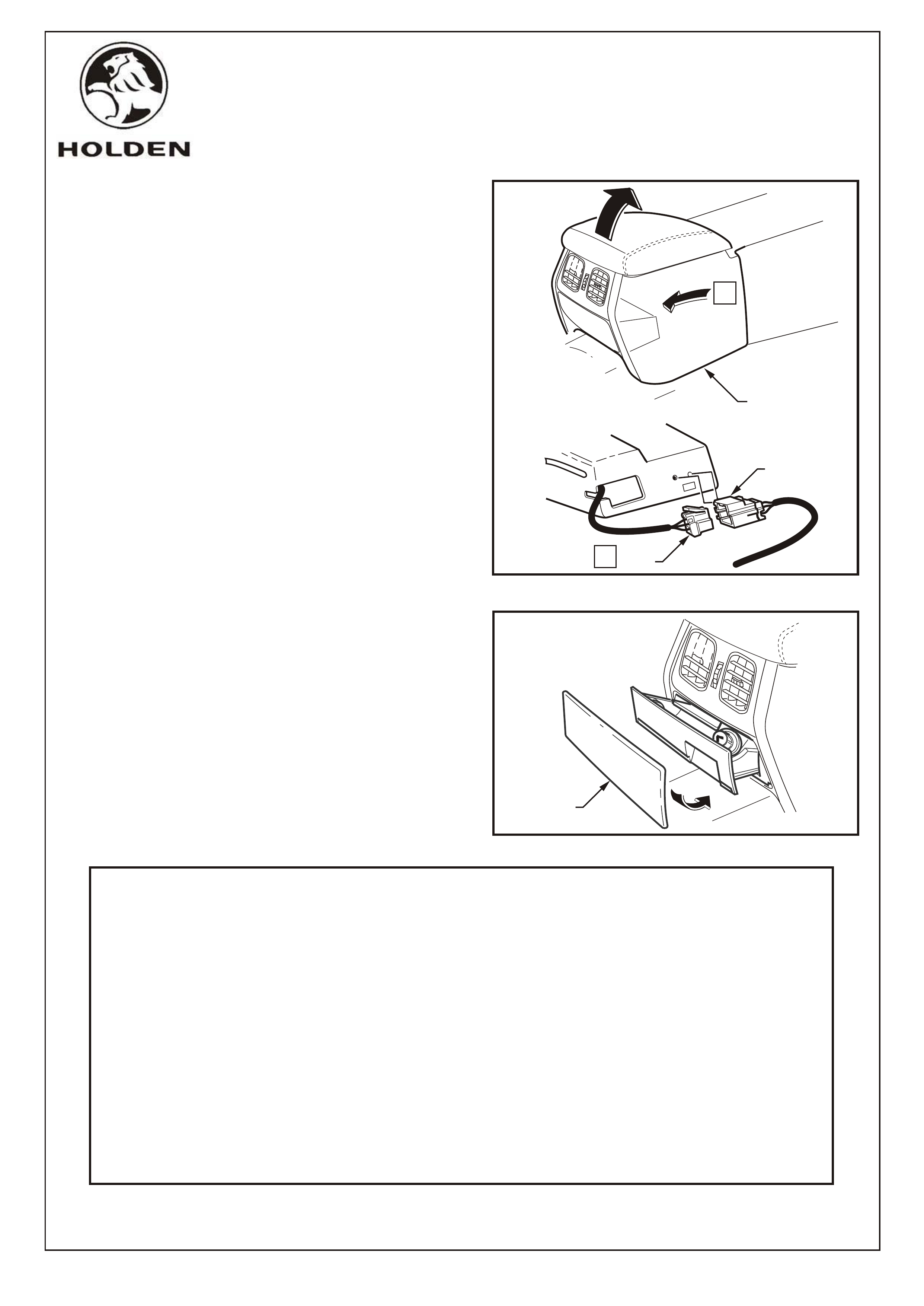
11. VY & WK
Remove the floor console cover assembly as follows.
Refer Figure 9.
A. Remove the screw (1) attaching the floor
console cover assembly (2).
NOTE: Vehicles fitted with navigation system do
not have this screw.
B. Prise the cover assembly from the floor console,
six places (3). Refer to View A.
C. Lift the cover assembly up from the rear,
disconnect the wiring connector (4) from the
side window switch assembly and any auxiliary
switches if fitted, and remove the cover
assembly.
12. VY & WK
Remove the instrument panel lower extension side
trims as follows. Refer Figure 10.
LEFT HAND SIDE TRIM REMOVAL:
A. Move the left hand front seat to its rearmost
position.
B. Remove the screw (1) attaching the instrument
panel lower extension side trim (2) to the floor
console. Refer to View A.
C. Open the instrument panel compartment and
remove the two screws (3) attaching the side
trim (2) to the instrument panel. Refer to View B.
D. Remove the side trim.
RIGHT HAND SIDE TRIM REMOVAL
A. Refer to Page 2, Step 3.
Page 5 of 10
COPYRIGHT
Reproduction in whole or part
prohibited without written approval
HOLDEN SERVICE PARTS OPERATIONS
Division of HOLDEN Ltd ACN 006 893 232
G791
1
4
1
11.0 - 3.0 Nm
A
2
FIGURE 9
3
A
VIEW
VY SHOWN
A
B
FIGURE 10
1
1
2
A
VIEW
B
13
2
VIEW
11.0 - 3.0 Nm
11.0 - 3.0 Nm VY SHOWN
FD1067
11MA03
Page 6 of 10
COPYRIGHT
Reproduction in whole or part
prohibited without written approval
FITTING INSTRUCTIONS: - continued
13. VY & WK
Remove the floor console compartment. Carefully
grasp the liner (1) and disengage the two lugs (2).
Refer Figure 11.
14. VY & WK
Remove the floor console as follows.
Refer to figures 12, 13 & 14.
A. For automatic transmission vehicles.
Refer Figure 12.
Remove the screw (1), four places, attaching the
console to the automatic transmission selector
assembly.
B. For manual transmission vehicles.
Refer Figure 13.
Use a fine flat-blade screwdriver to disengage
the lug (1), attaching the manual transmission
gear lever boot assembly (2) to the console, two
places front and rear. Remove the boot
assembly from the console and raise it over the
gear knob.
NOTE: Do not attempt to remove the gear knob
from the gear lever shaft as it is glued in place.
1
2
11.0 - 3.0 Nm
1
1
FIGURE 11
FIGURE 12
FIGURE 13
2
1
HOLDEN SERVICE PARTS OPERATIONS
Division of HOLDEN Ltd ACN 006 893 232
G791
FD1067
11MA03
VY SHOWN
VY SHOWN
Page 7 of 10
COPYRIGHT
Reproduction in whole or part
prohibited without written approval
FITTING INSTRUCTIONS: - continued
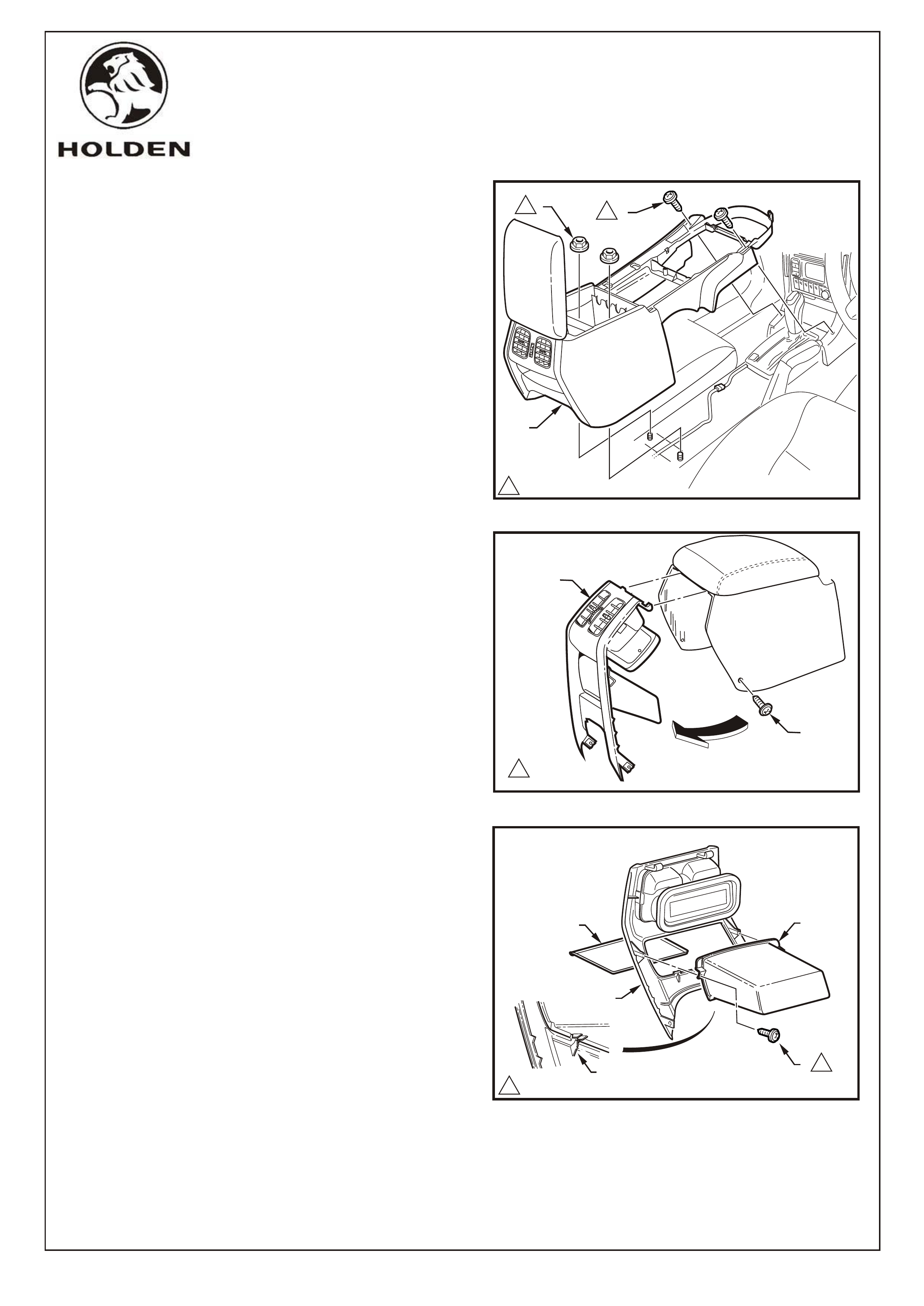
Refer Figure 14.
C. Remove the two nuts (1) attaching the floor
console (2) to the vehicle floor.
D. Remove the two screws (3) attaching the front of
the console to the instrument panel assembly.
E. As required, disconnect any console wiring
connectors.
F. Lift the rear of the console upward and remove.
NOTE: The console rear air duct will disconnect
from the console front air duct during removal.
The rear air duct will remain with the console.
15. VY & WK
Remove the rear air outlet housing as follows.
Refer Figure 15.
A. Remove the screw (1), one place each side,
attaching the floor console rear air outlet
housing assembly (2) to the floor console.
B. Remove the housing (2) by swinging the lower
edge rearward and detaching the upper tangs.
16. VY & WK
Remove the floor console rear compartment as
follows. Refer Figure 16.
A. Remove the rear compartment liner (1).
B. Remove the screw (3), two places attaching the
compartment to the rear air outlet housing
assembly (4).
C. Tilt the compartment (2) downwards slightly and
disengage the two lugs (5) from beneath the
compartment and remove.
1.0 - 3.0 Nm
3
2
1
1
1
1
11.0 - 3.0 Nm
1
2
1
1
3
5
2
1
4
1.0 - 3.0 Nm
FIGURE 14
FIGURE 15
FIGURE 16
HOLDEN SERVICE PARTS OPERATIONS
Division of HOLDEN Ltd ACN 006 893 232
G791
FD1067
11MA03
VY SHOWN
FITTING INSTRUCTIONS: - continued
17. VY & WK
Install the ashtray assembly (1) to the rear air outlet
housing assembly (2). Tighten the retaining screws to
the specified torque. Refer Figure 17.
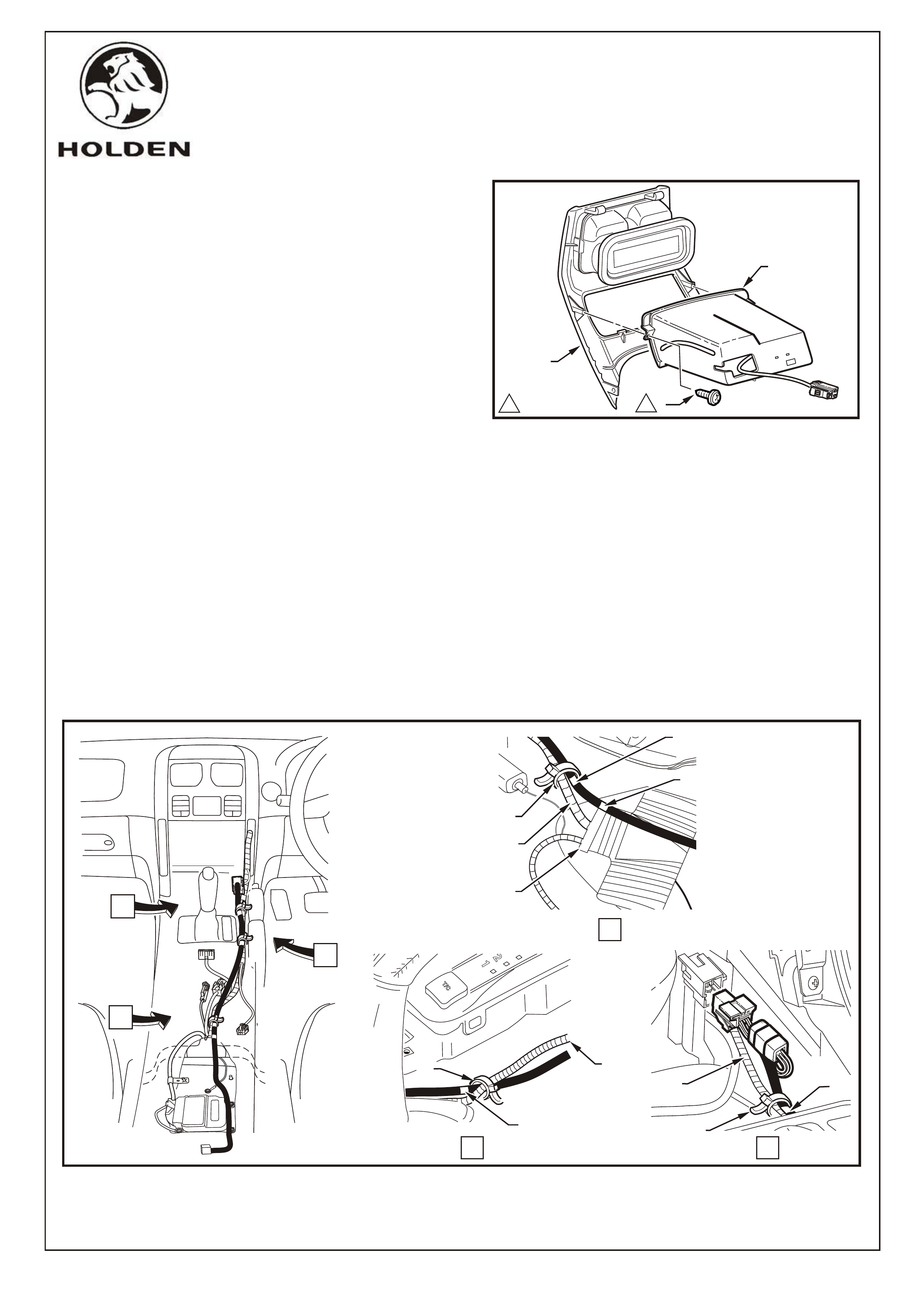
18. VY & WK
Install the rear patch harness. Refer Figure 18.
IMPORTANT:
To aid correct routing of the rear patch harness, the
harness has a white mark in four places. The patch
harness is tie strapped to the main wiring harness at
three of these white marks. The end of the harness
with two electrical connectors goes to the front of the
vehicle.
A. Loosely position the rear patch harness along
the right hand side of the transmission tunnel.
B. Align the first white band of the rear patch
harness (1) with the front edge of the main
vehicle wiring harness reinforcement stay (2).
Refer View A, Figure 18.
Page 8 of 10
COPYRIGHT
Reproduction in whole or part
prohibited without written approval
113
1
1.0 - 3.0 Nm
FIGURE 17
C. Whilst the first white band is aligned, tie-
strap (3) the rear patch harness at the
second white band (4) to the main vehicle
wiring harness (5).
Refer View A, Figure 18.
D. Tie-strap (6) the rear patch harness to the
main vehicle wiring harness (7) at the
third white band (8).
Refer to View B, Figure 18.
E. Tie-strap (9) the rear patch harness to the
main vehicle wiring harness (10) at the
fourth white band (11).
Refer to View C, Figure 18.
B
C
7
VIEW BVIEW C
FIGURE 18
VIEW A
11
T\CT\C
Power
Power
2
5
1
4
10 11
9
A
3
8
6
2
HOLDEN SERVICE PARTS OPERATIONS
Division of HOLDEN Ltd ACN 006 893 232
G791
FD1067
11MA03
11.0 - 3.0 Nm
3
1
2
Page 9 of 10
COPYRIGHT
Reproduction in whole or part
prohibited without written approval
FITTING INSTRUCTIONS: - continued
19. VY & WK
Connect the front patch harness connector/s as
follows.
Vehicles without front cigar lighter. Refer to Figure 19.
A. Tape the rear patch harness male connector (1)
(connector with foam tape) to the rear patch
harness (2).
B. Connect the female rear patch harness
connector (3) to the main wiring harness cigar
lighter connector (4).
Vehicles with front cigar lighter. Refer to Figure 20.
C. Disconnect the front cigar lighter harness
connector from the main wiring harness cigar
lighter connector.
D. Connect the female rear patch harness
connector (3) (connector without foam tape) to
the main wiring harness cigar lighter
connector (4).
E. Connect the female front cigar lighter harness
connector (5) with the remaining male rear
patch harness connector(1) (connector with
foam tape).
20. VY & WK
Position the rear patch lead (1) to the right of the
Airbag Control Module (2). Move both front seats to
their most forward position and loosely fit the console.
Refer to Figure 21.
21. VY & WK
Install the rear air outlet housing (1). Raise the
console (2) at the rear and hold the rear outlet duct at
its highest position so that the housing and duct are
correctly aligned during fitment. Tighten the retaining
screws (3) to the specified torque. Refer to Figure 22.
1
2
3
4
3
2
4
FIGURE 20
5
FIGURE 19
1
FIGURE 21
1
2
FIGURE 22
HOLDEN SERVICE PARTS OPERATIONS
Division of HOLDEN Ltd ACN 006 893 232
G791
FD1067
11MA03
VY SHOWN
FITTING INSTRUCTIONS: - continued
22. VY & WK
With the console (1) partially raised at the rear,
connect the rear patch harness connector (2) to the
cigar lighter harness connector (3), then clip the
assembled connectors to the rear of the ashtray. Refer
Figure 23.
23. VY & WK
Reconnect the battery. Check operation of the front (if
fitted) and rear cigar lighters. Reinstate the audio
system by entering the security code, by referring to
the owner’s manual.
CAUTION:
This may impact or damage electrical systems in the
vehicle, Body Control Module, Entertainment System,
Electric Sun Roof, etc unless correct instructions are
followed. Please contact your Holden Retailer for
further information.
24. VY & WK
25. VY & WK
Attach the rear ashtray colour coded fascia (1) by
locating the top of the fascia on the ashtray and
swinging the lower edge into position to achieve a
snap fit. Refer Figure 24.
NOTE: The rear ashtray fascia is not part of the
package and must be ordered as a separate part.
26. VY & WK
Place fitting instructions in the vehicles glovebox.
Refit the remaining components in the reverse order to
that of removal. Tighten the appropriate screws to their
specified torque.
Page 10 of 10
COPYRIGHT
Reproduction in whole or part
prohibited without written approval
1
FIGURE 23
A
VIEW A
2
3
FIGURE 24
1
HOLDEN SERVICE PARTS OPERATIONS
Division of HOLDEN Ltd ACN 006 893 232
G791
FD1067
11MA03
PART NUMBER DESCRIPTION QUANTITY
92146375 HOUSING ASM - REAR ASHTRAY 1
92146376 PLUNGER - CIGARETTE LIGHTER 1
92146377 RECEPTACLE - ASHTRAY 1
11062449 GLOBE - ASHTRAY LIGHTER 1
92146423 SOCKET & HARNESS ASM. - ASHTRAY 1
9214 5611 HARNESS - PATCH - REAR 1
TIE STRAPS 3
FD1067 FITTING INSTRUCTION BOOKLET 1
PARTS SUPPLIED SEPARATELY, NOT PART OF THE PACKAGE
VY
92121016 FASCIA - ASHTRAY (SS BLACK) 1
92121014 FASCIA - ASHTRAY (DARK TEMPEST) 1
92121017 FASCIA - ASHTRAY (CARRE MAPLE) 1
92121018 FASCIA - ASHTRAY (CHARCOAL MAPLE) 1
WK STATESMAN/CAPRICE
92121015 FASCIA - ASHTRAY (GREY GOLD) 1
VY AND WK STATESMAN/CAPRICE
REAR ASHTRAY/CIGAR LIGHTER PACKAGE
PARTS LIST
VY SHOWN
VY SHOWN