FD1069
11MA03
COPYRIGHT
Page 1 of 19
G673
HOLDEN SERVICE PARTS OPERATIONS
Reproduction in whole or part
prohibited without written approval
Division of HOLDEN Ltd ACN 006 893 232
FITTING INSTRUCTIONS FOR
VY CRUISE CONTROL PACKAGE,
V6 & SUPERCHARGED V6,
Part No. 92145711
FITTING INSTRUCTIONS:
NOTE: This Cruise Control Package is suitable for
vehicles fitted with traction control.
1. Disconnect the vehicle battery.
IMPORTANT: Disconnecting the vehicle battery may
impact or damage electrical systems in the vehicle - Body
Control Module, Entertainment System, Electric Sunroof,
etc unless correct instructions are followed. Please
contact your Holden Retailer for further information.
NOTE: To reinstate the audio system, the security code
will be required.
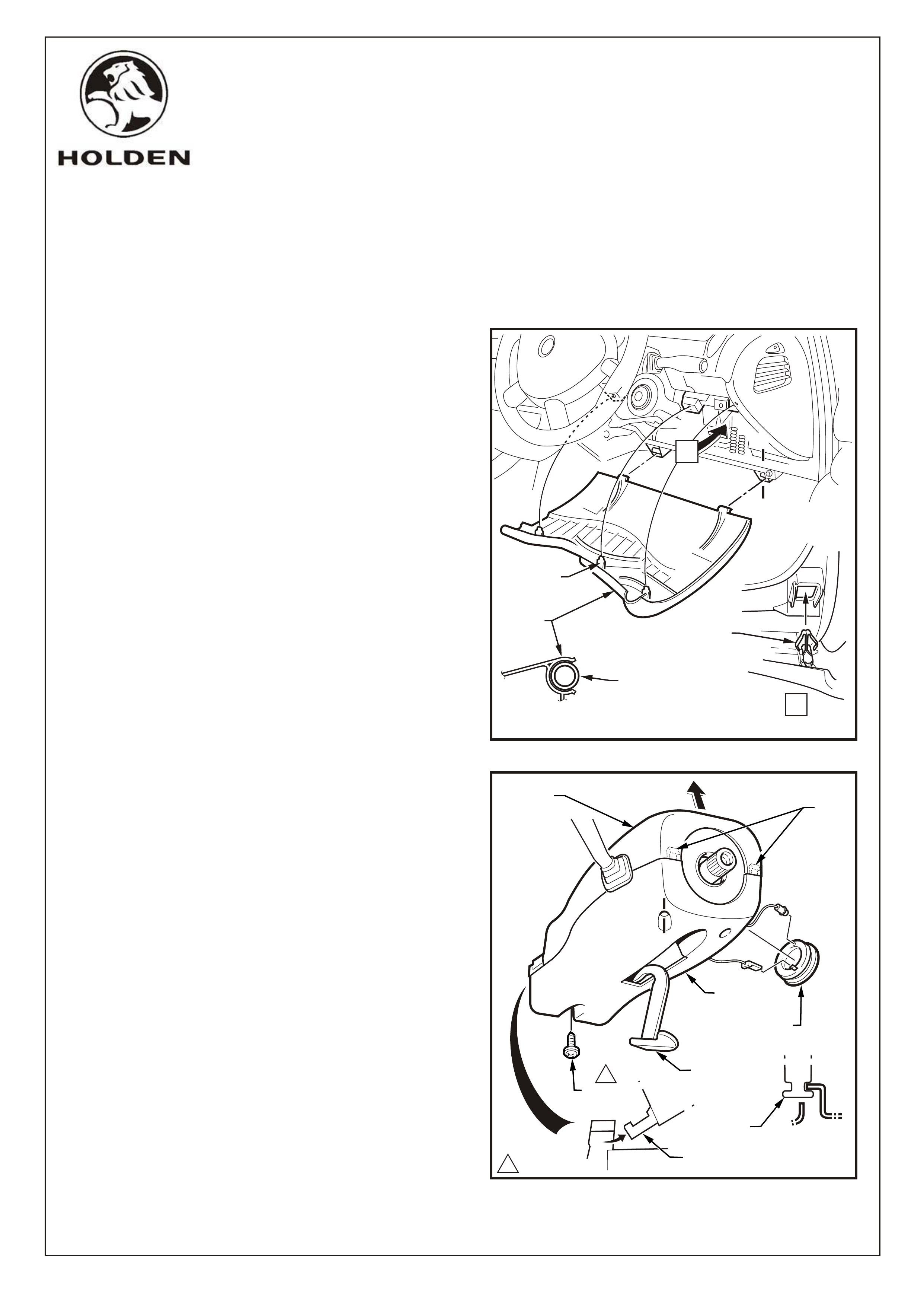
2. Remove the instrument panel, lower trim panel
assembly as follows:
Adjust steering wheel to upper most position.
Grasp the upper edge of the instrument panel
lower trim panel assembly and pull outwards to
disengage the three retaining clips.
Swing the panel assembly open.
Holding each side of the panel assembly pull
rearwards to disengage it from the instrument
panel lower trim panel retainer (two places).
Refer Figure 1.
3. Remove the upper and lower steering column covers
as follows:
Release the steering column adjustment lever and
move the column to its lowest position.
NOTE: The steering wheel does not need to be
removed. It is not shown for clarity only.
From below the steering column, remove the screw
attaching the lower cover.
Depress the face of the lower cover inwards to
disengage the tabs and lift the steering column
upper cover.
Raise the upper cover as high as possible to
disengage the lugs and remover the cover.
Remove the theft deterrent receiver assembly from
the steering column lower cover.
Disconnect the wiring connector and globe socket
from the receiver assembly.
Slide the lower cover rearward to disengage it form
the lugs and remove the cover.
Refer Figure 2.
TOOLS REQUIRED:
Hole saw (20mm), Centre Punch, Phillips Head Screw Driver, Flat Blade Screwdriver, 10mm Socket,
Torx Bit T25 Corrosion Protection Paint.,
FITTING INSTRUCTIONS FOR
VY CRUISE CONTROL PACKAGE, V6 & SUPERCHARGED V6,
Part No. 92145711
COPYRIGHT
Page 2 of 19
HOLDEN SERVICE PARTS OPERATIONS
Reproduction in whole or part
prohibited without written approval
Division of HOLDEN Ltd ACN 006 893 232
FIGURE 1
LOWER
TRIM
PANEL
A-A
A
A
A
A
RETAINING
CLIP
RETAINING
CLIP
(3 PLACES)
LOWER TRIM
PANEL
RETAINER
(2 PLACES)
UPPER
COVER
SCREW
ADJUSTMENT
LEVER
A-A
A
A
10.5 - 2.0 Nm
FIGURE 2
LOWER
COVER
TABS
THEFT DETERRENT
RECEIVER
LUGS
LUGS
1
G673
FD1069
11MA03
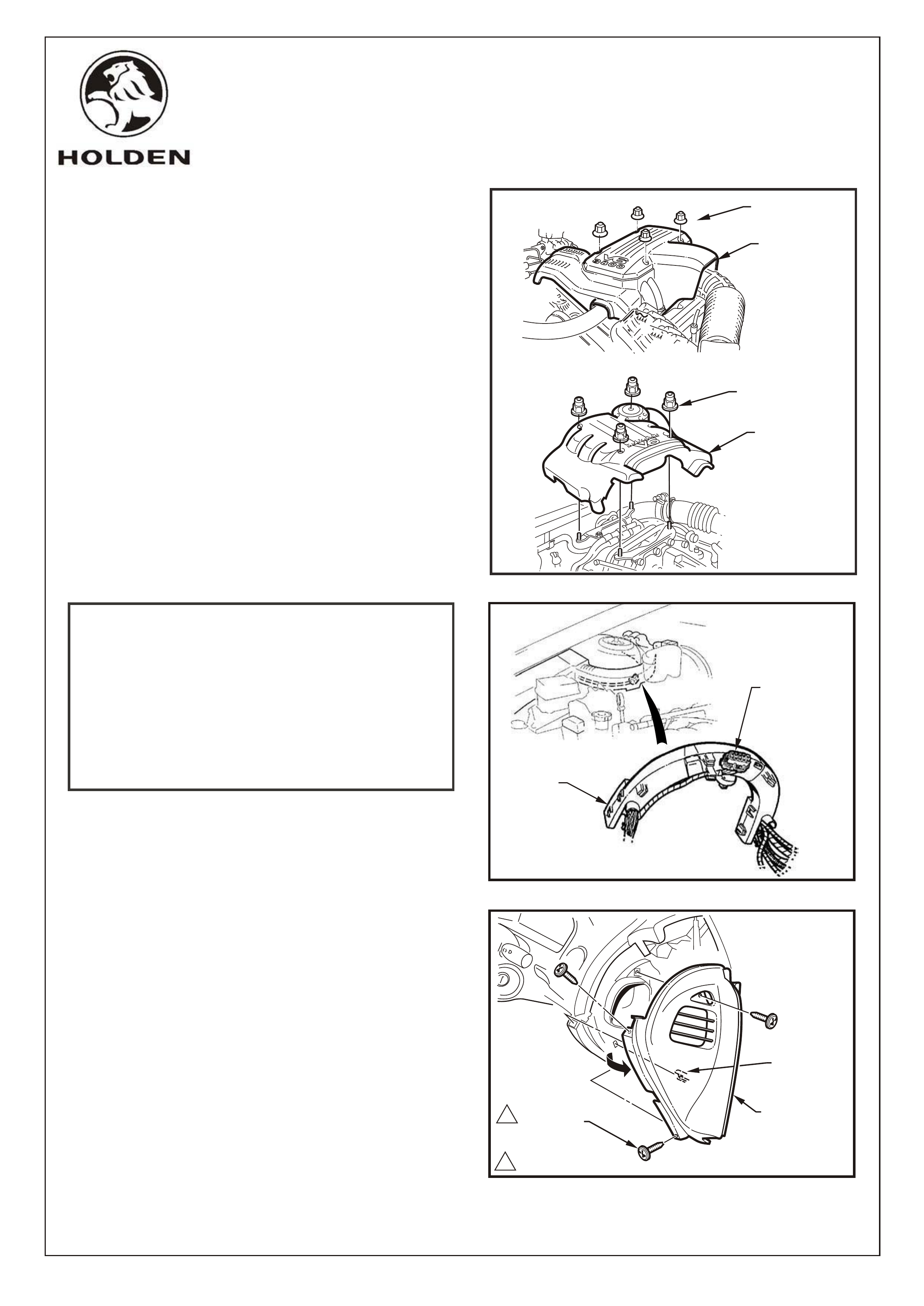
4. Remove the four dome nuts securing the engine
dress cover and remove cover. Refer Figure 3.
NOTE: For MANUAL TRANSMISSION vehicles also
refer to page 18 of these instructions for additional
procedures.
IMPORTANT: Check if the stepper motor connector
is clipped to the underside of the strut tower former, as
part of the original wiring harness. Refer Figure 4.
If connector exists, go to Step 50.
If connector does not exist, continue installation as
described below.
5. Remove the right and left-hand instrument panel
outer covers as follows:
Remove the three screws attaching the right and
left-hand instrument panel outer covers to the
instrument panel.
Remove the cover by rotating outward to
disengage the retaining clip and the ventilation
ducts.
Refer Figure 5 (right-hand side shown).
COPYRIGHT
Page 3 of 19
HOLDEN SERVICE PARTS OPERATIONS
Reproduction in whole or part
prohibited without written approval
Division of HOLDEN Ltd ACN 006 893 232
STEPPER
MOTOR
CONNECTOR
STRUT
TOWER
FORMER
FIGURE 3
FIGURE 4
FIGURE 5
11.0 - 3.0 Nm
1SCREW
(3 PLACES) INSTRUMENT
PANEL OUTER
COVER
RETAINING
CLIP
G673
V6
SUPERCHARGED V6
DOME NUTS
(4 PLACES)
ENGINE DRESS
COVER
ASSEMBLY
ENGINE DRESS
COVER
ASSEMBLY
DOME NUTS
(4 PLACES)
FD1069
11MA03
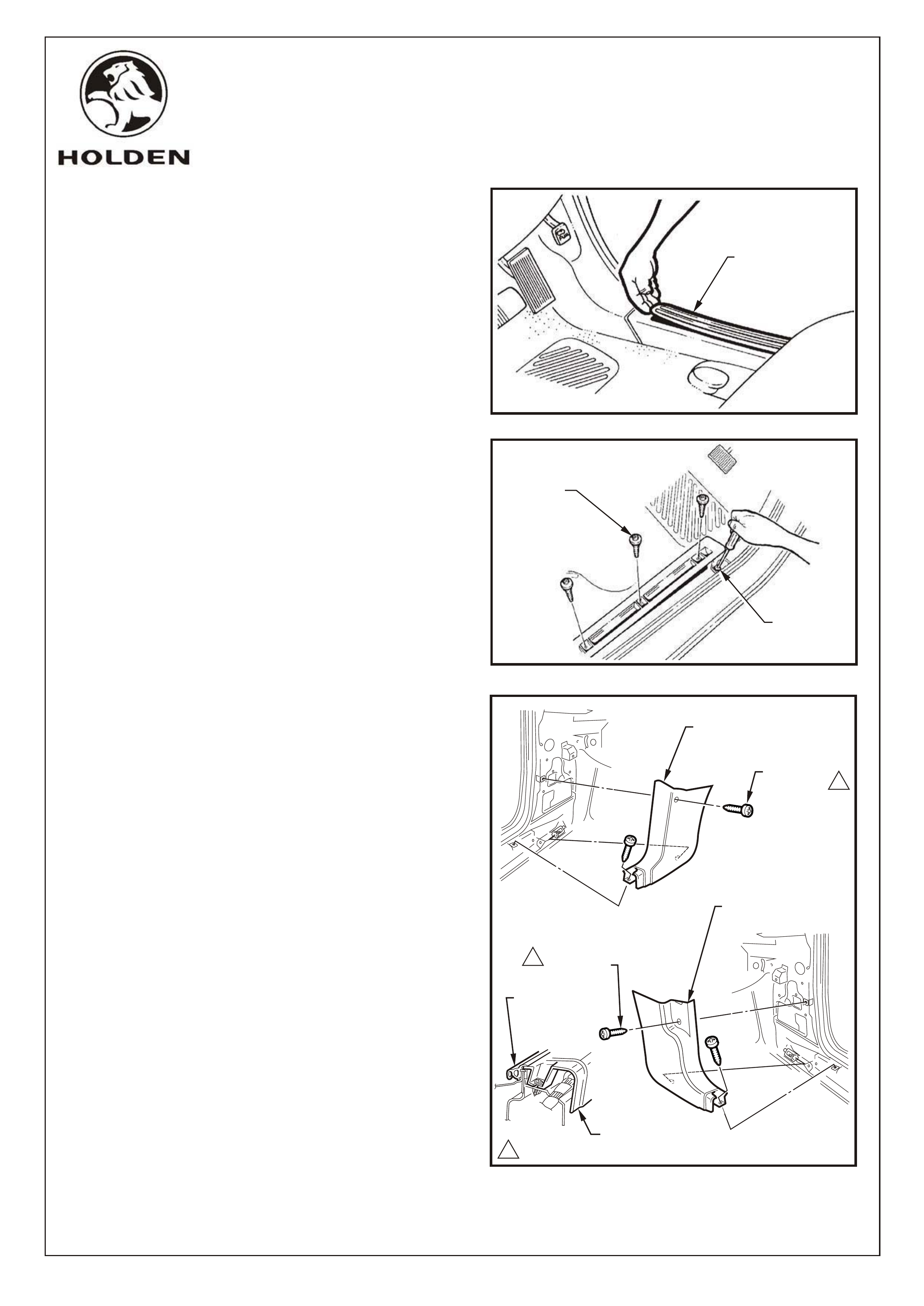
6. Remove the right and left-hand side rocker panel
cover inserts.
Refer Figure 6.
7. Remove the front three TORX head screws and
loosen the rear most screw with TORX bit T25 on the
right and left-hand sides. Refer Figure 7.
8. Lift the front of the inner rocker panel cover to gain
access to the screw securing the hinge pillar trim
assembly to the rocker panel. Refer Figure 7.
9. Remove the right and left-hand side hinge pillar trim
assemblies as follows:
Remove the two attaching screws from the hinge
pillar trim assembly.
Disengage the hinge pillar trim clip by pulling the
lower edge of the hinge pillar trim assembly up and
away from the sheet metal.
NOTE: When refitting, ensure the outer edge of the
hinge pillar trim assembly engages the door
opening weatherstrip.
Refer Figure 8.
COPYRIGHT
Page 4 of 19
HOLDEN SERVICE PARTS OPERATIONS
Reproduction in whole or part
prohibited without written approval
Division of HOLDEN Ltd ACN 006 893 232
TORX HEAD
SCREW
(3 PLACES)
SCREW
ROCKER PANEL
COVER INSERT
FIGURE 6
FIGURE 7
SCREW
(2 PLACES)
1
1
1
0.7 - 1.0 Nm
FIGURE 8
RIGHT-HAND SIDE
HINGE PILLAR TRIM
SCREW
(2 PLACES)
LEFT-HAND SIDE
HINGE PILLAR TRIM
HINGE PILLAR TRIM
DOOR OPENING
WEATHERSTRIP
G673
FD1069
11MA03
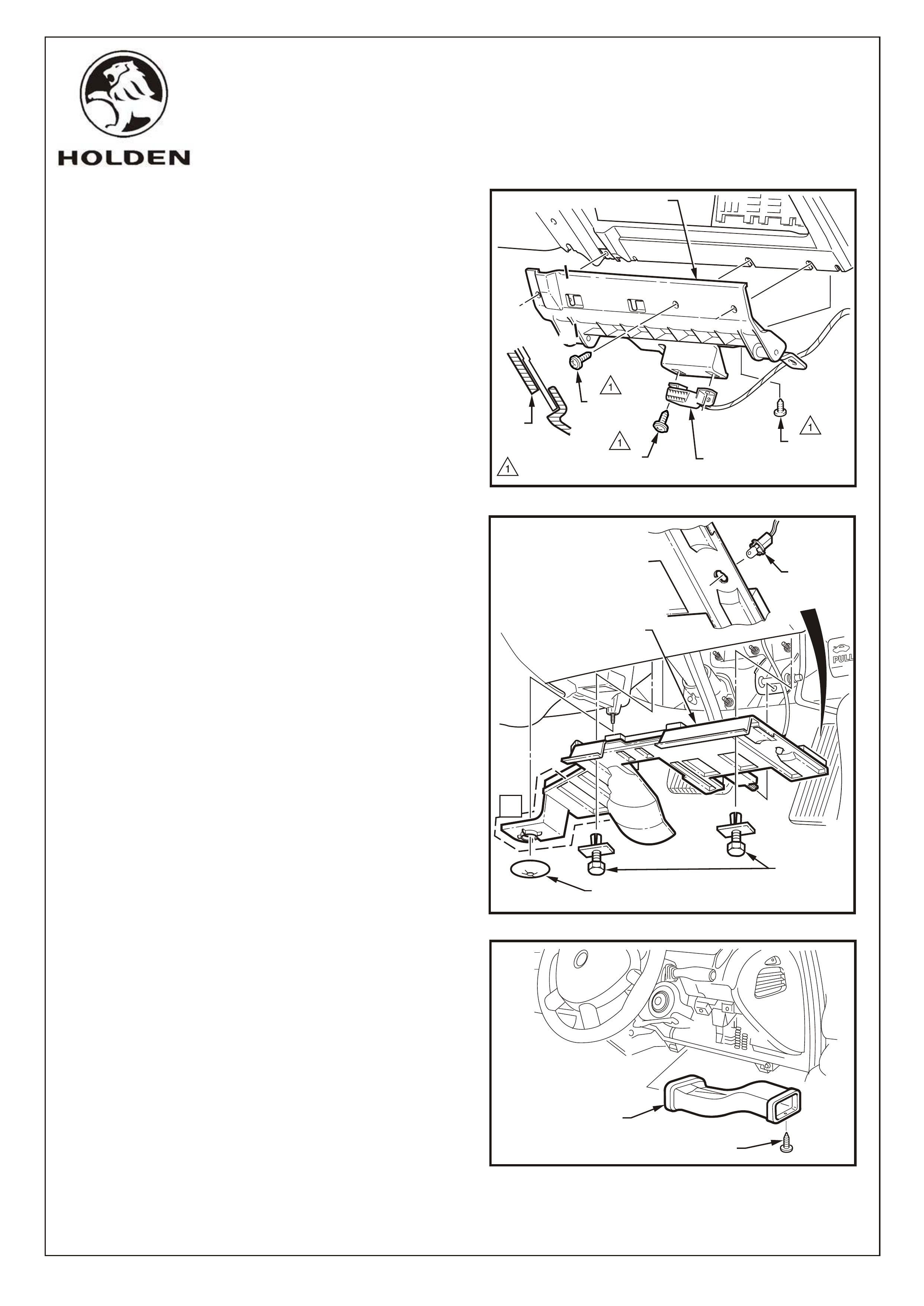
10. Remove the 2 screws attaching the data link
connector to the instrument panel lower trim panel
retainer. Refer Figure 9.
11. Remove the instrument panel lower trim panel
retainer as follows:
Remove the screw attaching the retainer to the air
duct.
Remove the three screws attaching the retainer to
the instrument panel assembly and the instrument
panel.
Slide the retainer downward to disengage the two
lugs from the instrument panel assembly as shown
at Section A-A and remove the retainer.
Refer Figure 9.
12. Remove the right-hand side instrument panel lower
trim plate assembly as follows:
Remove the retainer attaching the instrument
panel lower trim plate assembly to the HVAC unit
(Automatic Transmission Vehicles only).
NOTE: The area shown A is not present on Manual
Transmission vehicles.
Loosen the screw and remove the retainer (2
places) attaching the plate assembly to the
instrument panel.
Lower the plate assembly slightly and withdraw the
lug from the pedal bracket.
If fitted, remove the stepwell lamp by rotating the
socket and removing from the plate assembly.
Remove the plate assembly.
Refer Figure 10.
13. Remove right-hand side ventilation duct.
Refer Figure 11.
COPYRIGHT
Page 5 of 19
HOLDEN SERVICE PARTS OPERATIONS
Reproduction in whole or part
prohibited without written approval
Division of HOLDEN Ltd ACN 006 893 232
FIGURE 9
FIGURE 10
RETAINER (AUTOMATIC
TRANSMISSION VEHICLES ONLY)
A
RETAINER
(2 PLACES)
INSTRUMENT PANEL
LOWER TRIM PLATE
ASSEMBLY
STEPWELL
LAMP
FIGURE 11
RIGHT-HAND SIDE
VENTILATION DUCT
SCREW
G673
1.0 - 3.0 Nm
A
A
A-A DATA LINK
CONNECTOR
SCREW
(2 PLACES)
SCREW
(AIR DUCT)
SCREW
(3 PLACES)
LUG
LOWER TRIM PANEL RETAINER
FD1069
11MA03
COPYRIGHT
Page 6 of 19
HOLDEN SERVICE PARTS OPERATIONS
Reproduction in whole or part
prohibited without written approval
Division of HOLDEN Ltd ACN 006 893 232
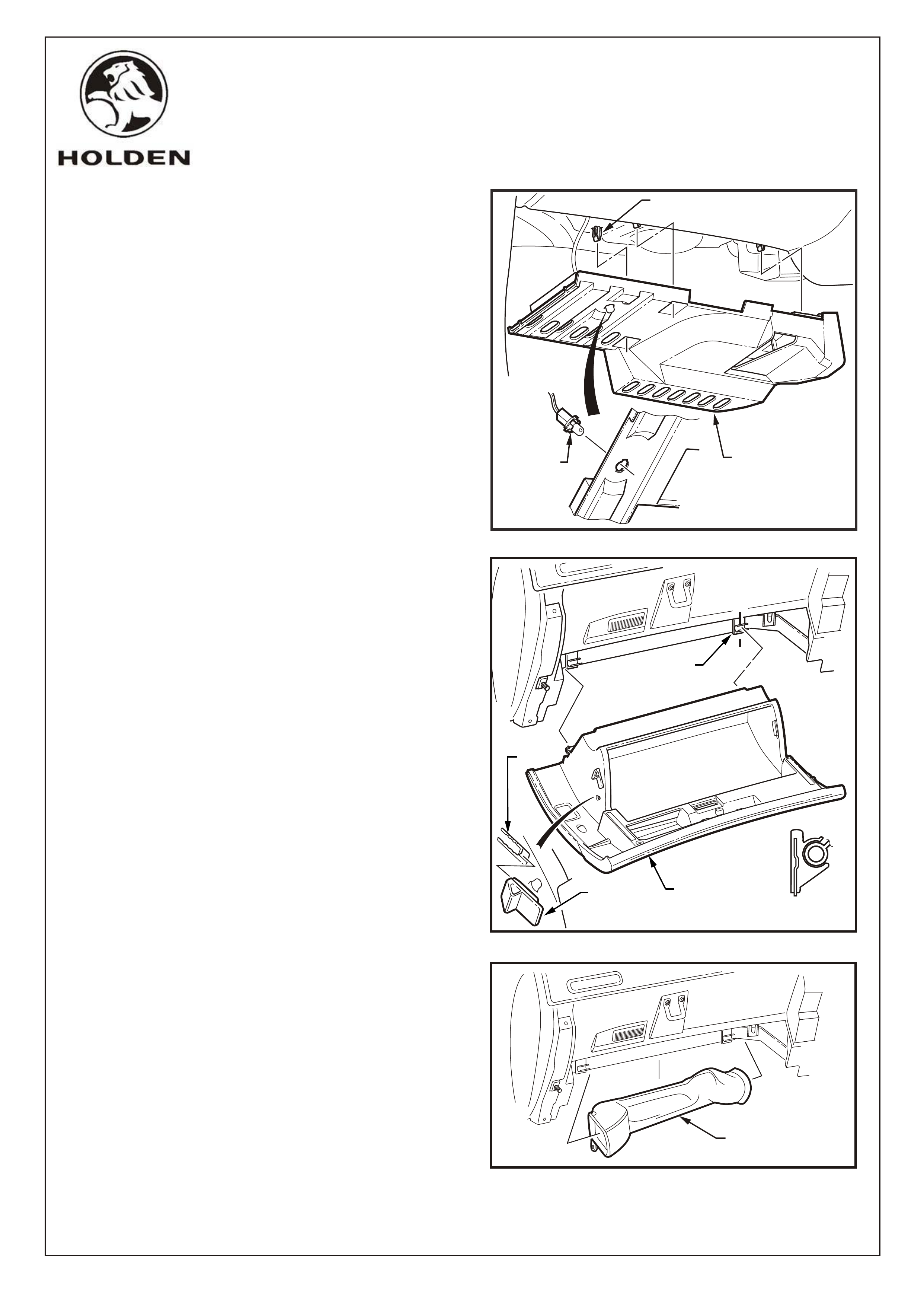
14. Remove the left-hand side instrument panel lower
trim plate assembly as follows:
Grasp the instrument panel lower trim plate
assembly and carefully pull downward to
disengage the retaining clips (3 places).
Lower the plate assembly slightly and if fitted
remove the stepwell lamp by rotating the socket
and removing from the plate assembly.
Remove the plate assembly.
Refer Figure 12.
15. Remove the instrument compartment assembly as
follows:
Open the instrument compartment assembly.
Using a fine flat-blade screwdriver, flatten the
instrument panel compartment bumper stop each
side and carefully open the compartment assembly
fully.
From the inside of the compartment assembly,
push outwards on the bumper stop and slide the
bumper from the lug. Repeat for the opposite side.
Close the compartment assembly half way and
grasping each side pull rearward to disengage the
compartment assembly from each instrument
panel compartment hinge.
Refer Figure 13.
NOTE: Take care when disengaging the hinges as
removing the compartment assembly on the wrong angle
may cause damage.
16. Remove right-hand side ventilation duct.
Refer Figure 14.
FIGURE 12
STEPWELL
LAMP
LEFT-HAND SIDE
INSTRUMENT PANEL
LOWER TRIM PLATE
CLIP
(3 PLACES)
A-A
A
FIGURE 13
A
INSTRUMENT
PANEL
COMPARTMENT
HINGE
BUMPER
STOP
LUG
LEFT-HAND SIDE
VENTILATION DUCT
FIGURE 14
G673
FD1069
11MA03
3
SCREWS
(4 PLACES)
INSTRUMENT
CLUSTER
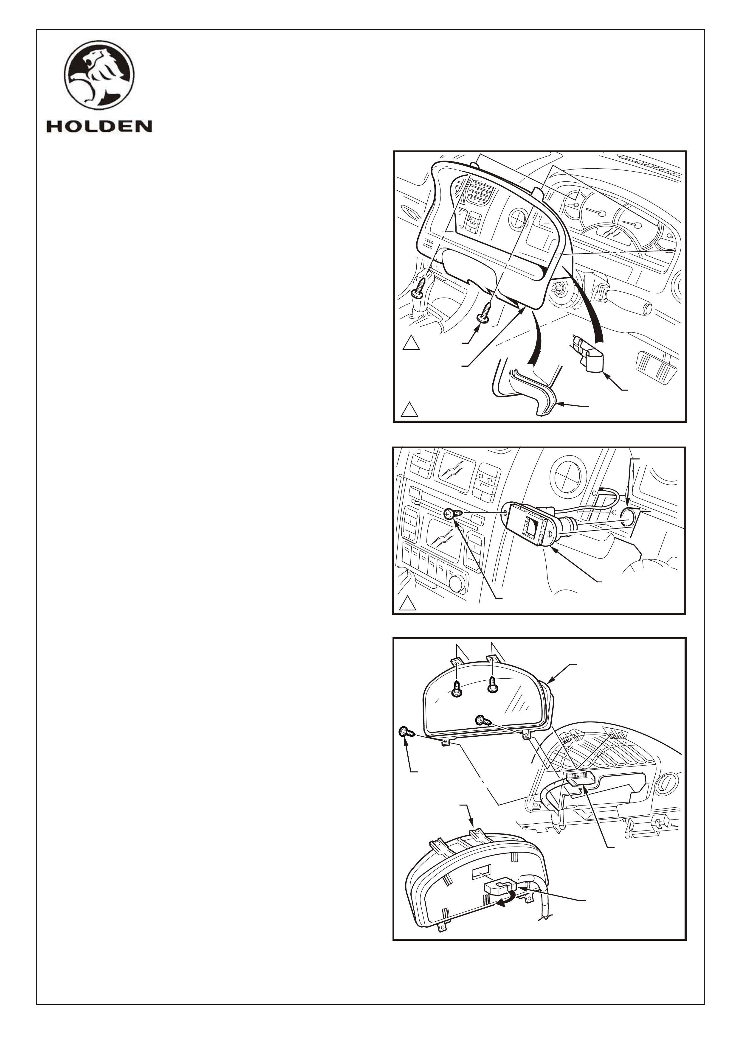
17. Remove the instrument cluster trim panel assembly
as follows:
NOTE: The steering wheel is not shown for clarity, the
cluster trim can be removed with the steering wheel
installed.
Release the steering column adjustment lever and
move the steering column to its lowest position.
Remove the two screws attaching the instrument
cluster trim assembly to the instrument panel.
Depress the top of the trim assembly slightly and tilt
the top of the trim assembly out of the instrument
panel pad, disengaging the retaining clips (3
places) each side.
Unhook each lug from the instrument panel pad.
Remove the trim assembly.
Refer Figure 15
in-car air
temperature sensor
19. Remove the instrument cluster as follows:
Remove the four screws attaching the instrument
cluster to the instrument panel.
Roll the top of the instrument cluster from its cavity.
Using a fine flat blade screwdriver, open the wiring
connector locking tab on the back of the cluster.
Remove the cluster assembly.
Refer Figure 17.
NOTE: When reinstalling the instrument cluster,
tighten the screws in the sequence indicated.
Refer Figure 17.
18. Remove the screw attaching the
to the instrument panel. Extract
the sensor assembly from the cavity and disconnect
the air tube. Refer Figure 16.
COPYRIGHT
Page 7 of 19
HOLDEN SERVICE PARTS OPERATIONS
Reproduction in whole or part
prohibited without written approval
Division of HOLDEN Ltd ACN 006 893 232
11.0 - 3.0 Nm
.
.
.
..
.
.
.
.
.
.
.
.
.
.
.
.
.
.
.
.
.
.
.
.
.
.
.
.
.
.
.
..
.
.
.
.
.
.
.
.
.
.
.
.
.
.
.
.
.
.
.
.
IN-CAR
TEMPERATURE
SENSOR
FIGURE 16
SCREW
FIGURE 15
11.0 - 3.0 Nm
1SCREWS
CLIPS
(3 PLACES
EACH SIDE)
LUG
INSTRUMENT
CLUSTER
TRIM ASSEMBLY
2
4
1
INSTRUMENT
CLUSTER
WIRING
CONNECTOR
WIRING
CONNECTOR
FIGURE 17
AIR TUBE
G673
FD1069
11MA03
COPYRIGHT
Page 8 of 19
HOLDEN SERVICE PARTS OPERATIONS
Reproduction in whole or part
prohibited without written approval
Division of HOLDEN Ltd ACN 006 893 232
FIGURE 18
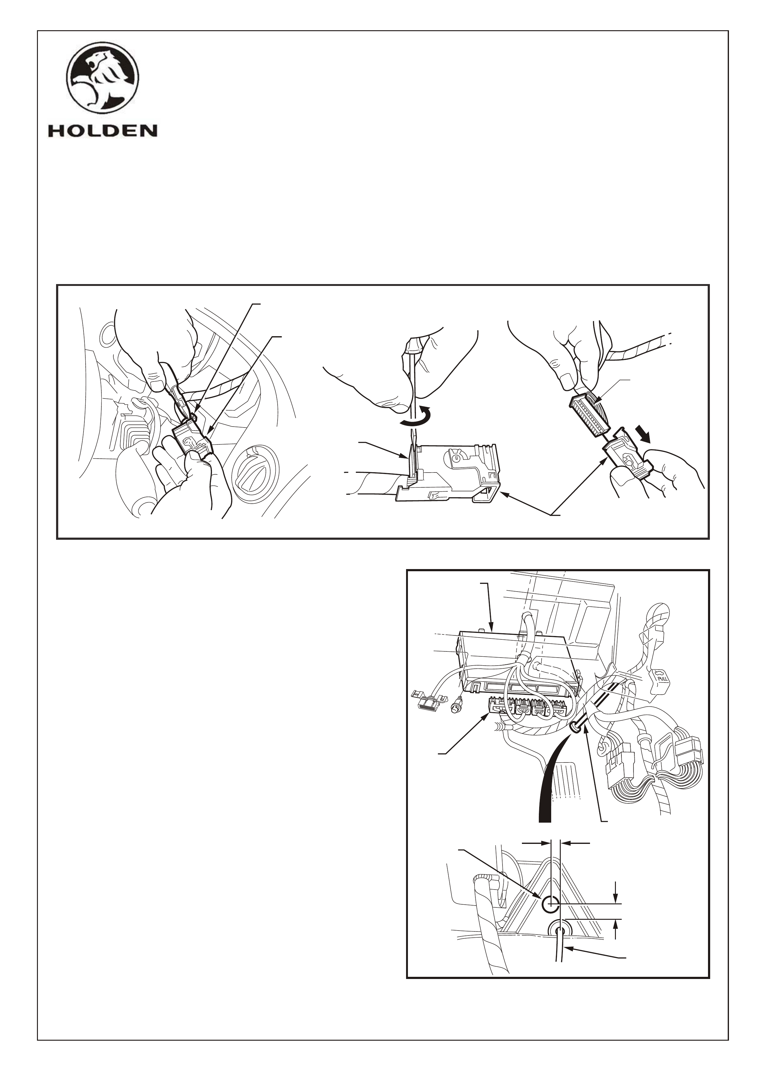
20. Cut the cable tie securing the instrument cluster
connector housing to the wiring harness.
Refer Figure 18.
21. Place a small flat blade screwdriver between the front
edge of the connector housing and the inner
connector. Twist as shown to release the housing and
withdraw from the inner connector. Refer Figure 18.
INSTRUMENT CLUSTER
WIRING CONNECTOR
CUT CABLE TIE
CONNECTOR
HOUSING
INNER
CONNECTOR
INNER
CONNECTOR
TWIST TO
RELEASE
20.0
5.0
BONNET
RELEASE CABLE
DRILL
20.0 mm DIA
HOLE
FIGURE 19
REMOVE BCM
FROM MOUNT
BONNET
RELEASE
CABLE
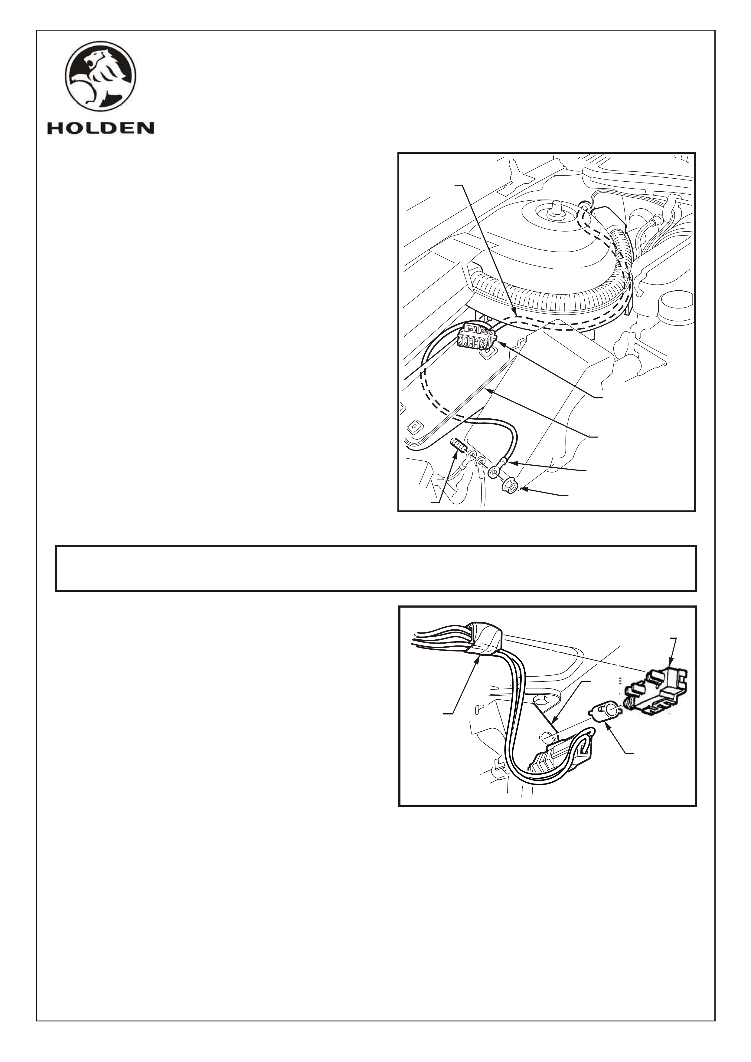
22. Detach the BCM from its mount, disconnect the wiring
connectors and remove the BCM. Refer Figure 19.
23. Mark and centre punch the hole location on the
firewall, above the bonnet release cable. Refer
Figure 19.
NOTE: Prior to drilling, cover the carpet to protect
from iron filings.
24. Drill a 20mm dia. hole with a hole saw. Deburr and
coat the bare metal with anti-corrosion primer.
25. From the engine compartment, insert the cruise
control engine bay patch harness (part number
92066684) through the drilled hole and seat the
grommet in the hole securely.
26. Refit the BCM and reconnect the wiring connectors.
BCM
WIRING
CONNECTORS
G673
FD1069
11MA03
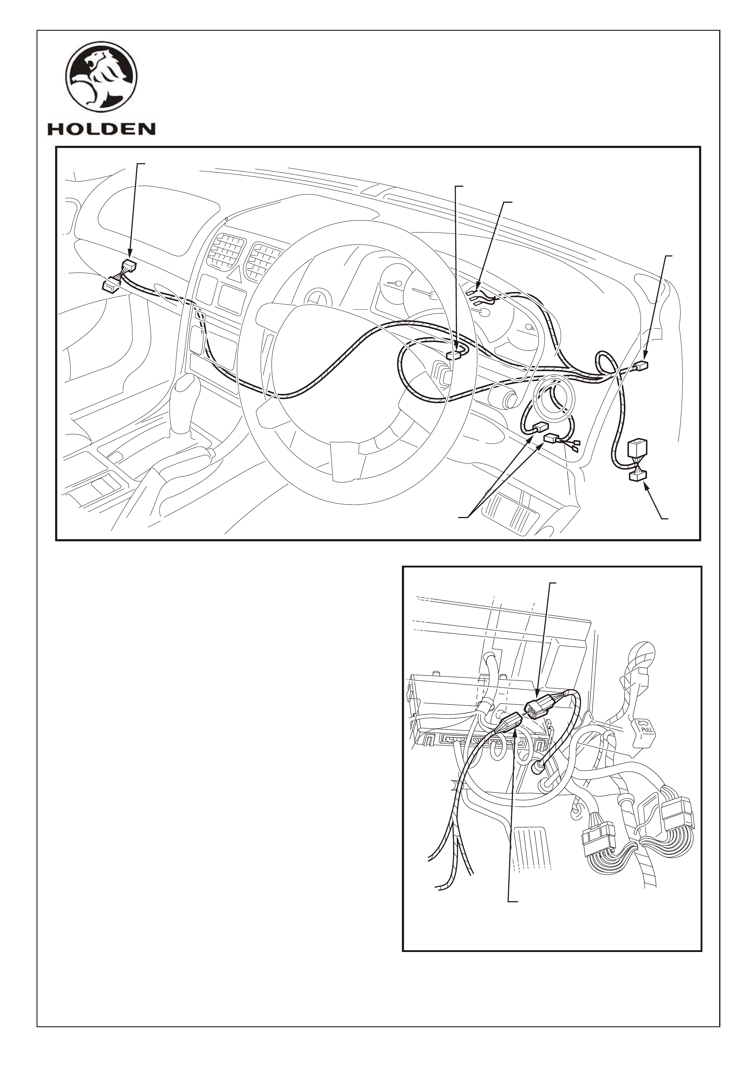
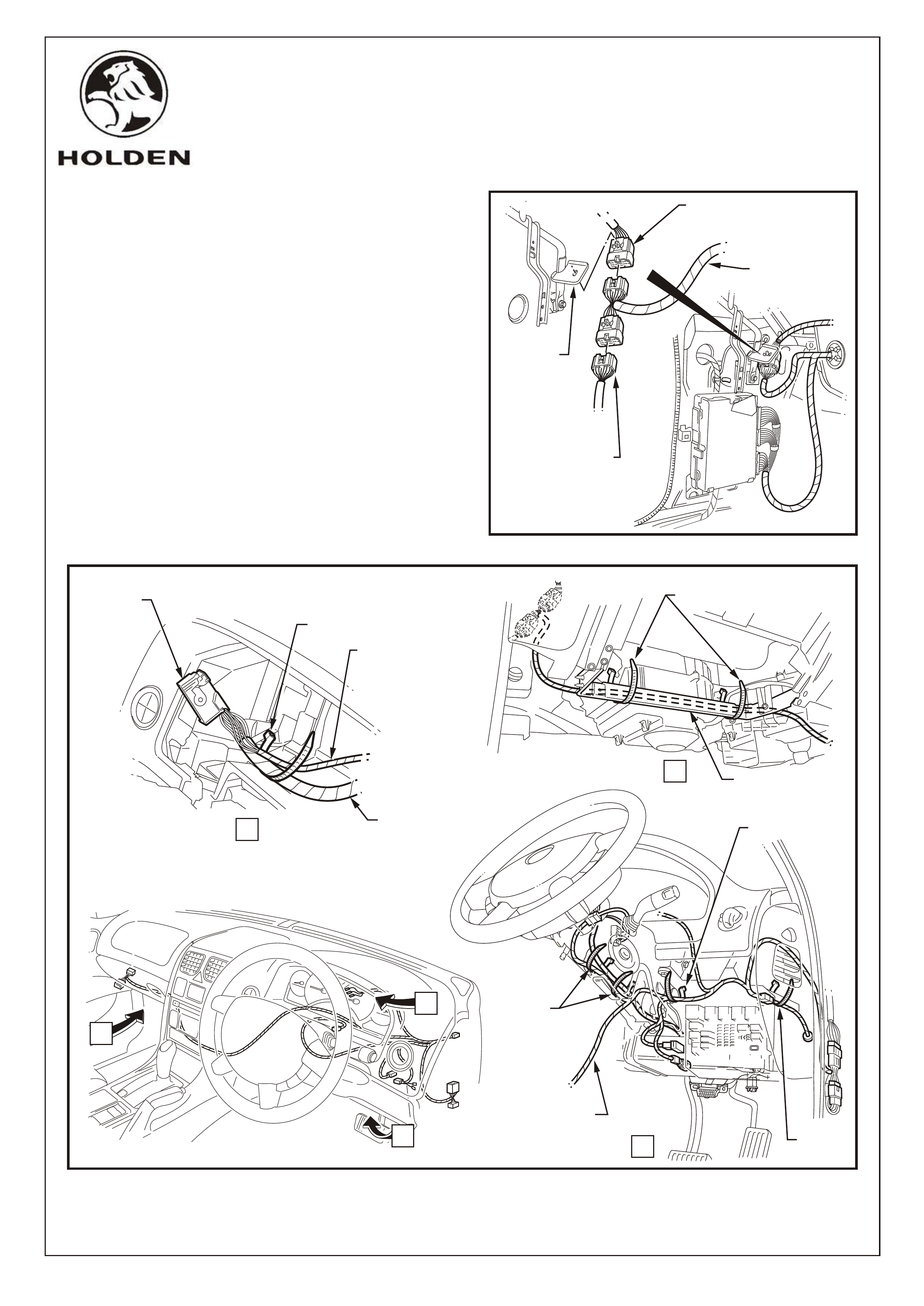
27. Connect the cruise control cabin patch harness 9
Pin connector to the corresponding cruise control
engine bay harness 9 Pin connector previously
installed (1) and route through the dash framework
above the fuse panel.
Refer Figures 20 & 21.
COPYRIGHT
Page 9 of 19
HOLDEN SERVICE PARTS OPERATIONS
Reproduction in whole or part
prohibited without written approval
Division of HOLDEN Ltd ACN 006 893 232
FIGURE 20
GENERAL CRUISE CONTROL CABIN PATCH HARNESS ROUTING
(2)
(6)
FIGURE 21
CRUISE CONTROL
ENGINE BAY PATCH
HARNESS CONNECTOR
CRUISE CONTROL
CABIN PATCH
HARNESS CONNECTOR
(4)
(3)
(1)
(5)
G673
FD1069
11MA03
COPYRIGHT
Page 10 of 19
HOLDEN SERVICE PARTS OPERATIONS
Reproduction in whole or part
prohibited without written approval
Division of HOLDEN Ltd ACN 006 893 232
BODY
HARNESS
CONNECTOR
MAIN WIRING
HARNESS
CONNECTOR
CRUISE CONTROL
CABIN PATCH
HARNESS
CONNECTORS
FIGURE 22
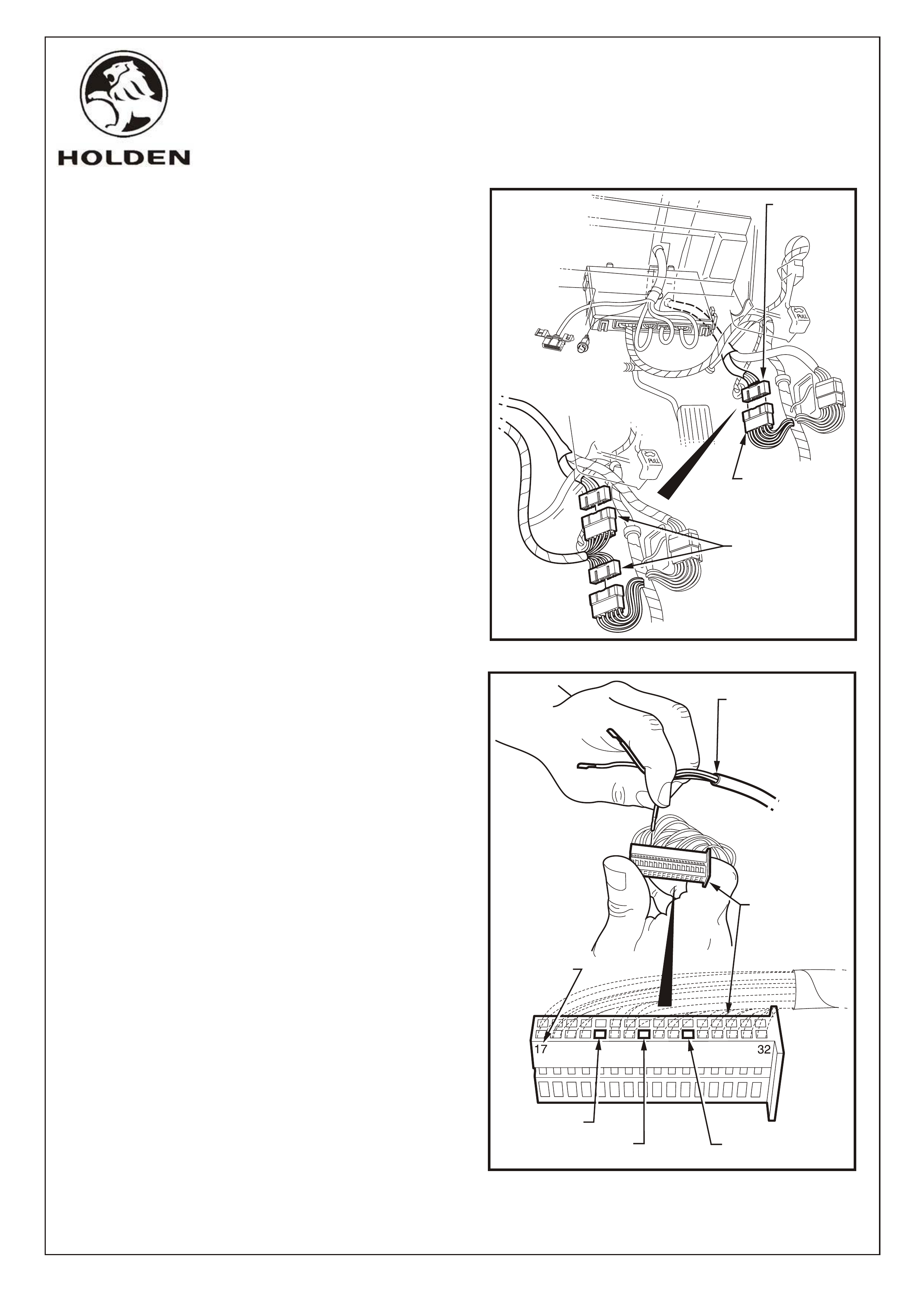
28. Route the two, 22 Pin connectors through the dash
framework to the right-hand side kick panel (2).
Refer Figure 21.
29. Disconnect the main wiring harness 22 Pin
connector and the body harness 22 Pin connector
and connect the corresponding connectors from the
cruise control cabin patch harness.
Refer Figure 22.
30. Route the section of the harness with the three
exposed wires over the steering column bracket,
back through the hole in the panel and alongside
the existing harness to the instrument cluster
connector (3). Refer Figure 20.
31. Determine the pin numbering sequence on the
inner connector (stamped on the side of the
connector body) and insert the cruise control cabin
patch harness wires as follows:
WHITE WIRE - PIN 21
YELLOW/RED WIRE - PIN 24 (Refer Note*)
GREY WIRE - PIN 27
*NOTE: Some vehicles may already have a
Yellow/Red wire at pin location 24. If present,
remove the wire, insulate, tape back and insert the
cruise control patch harness Yellow/Red wire.
Ensure the wires are securely fitted then
reassemble the inner connector to the housing
connector and secure with a cable tie.
Refer Figure 23.
32. Reconnect the instrument cluster connector and
reinstall the instrument cluster.
Refer Figures 17 &18.
21 - WHITE
24 - YELLOW/RED
REFER TO NOTE*, STEP 31
27 - GREY
PIN
NUMBERS
INSTRUMENT
CLUSTER
INNER
CONNECTOR
CRUISE
CONTROL CABIN
PATCH HARNESS
FIGURE 23
G673
FD1069
11MA03
COPYRIGHT
Page 11 of 19
HOLDEN SERVICE PARTS OPERATIONS
Reproduction in whole or part
prohibited without written approval
Division of HOLDEN Ltd ACN 006 893 232
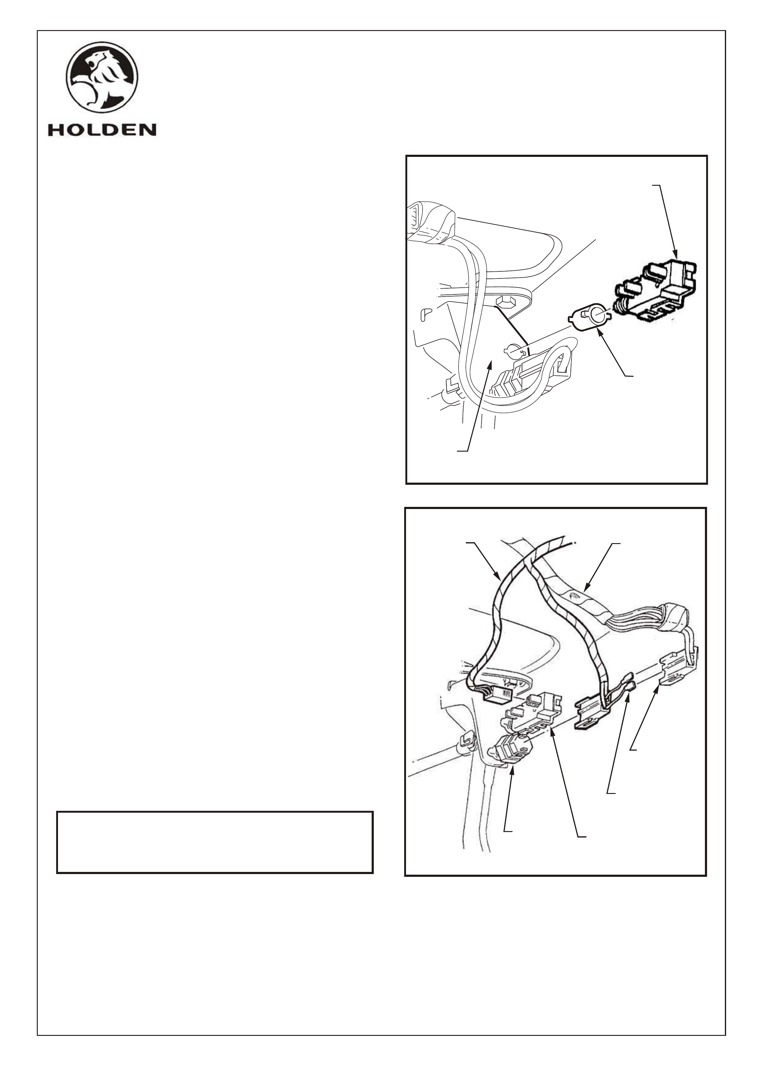
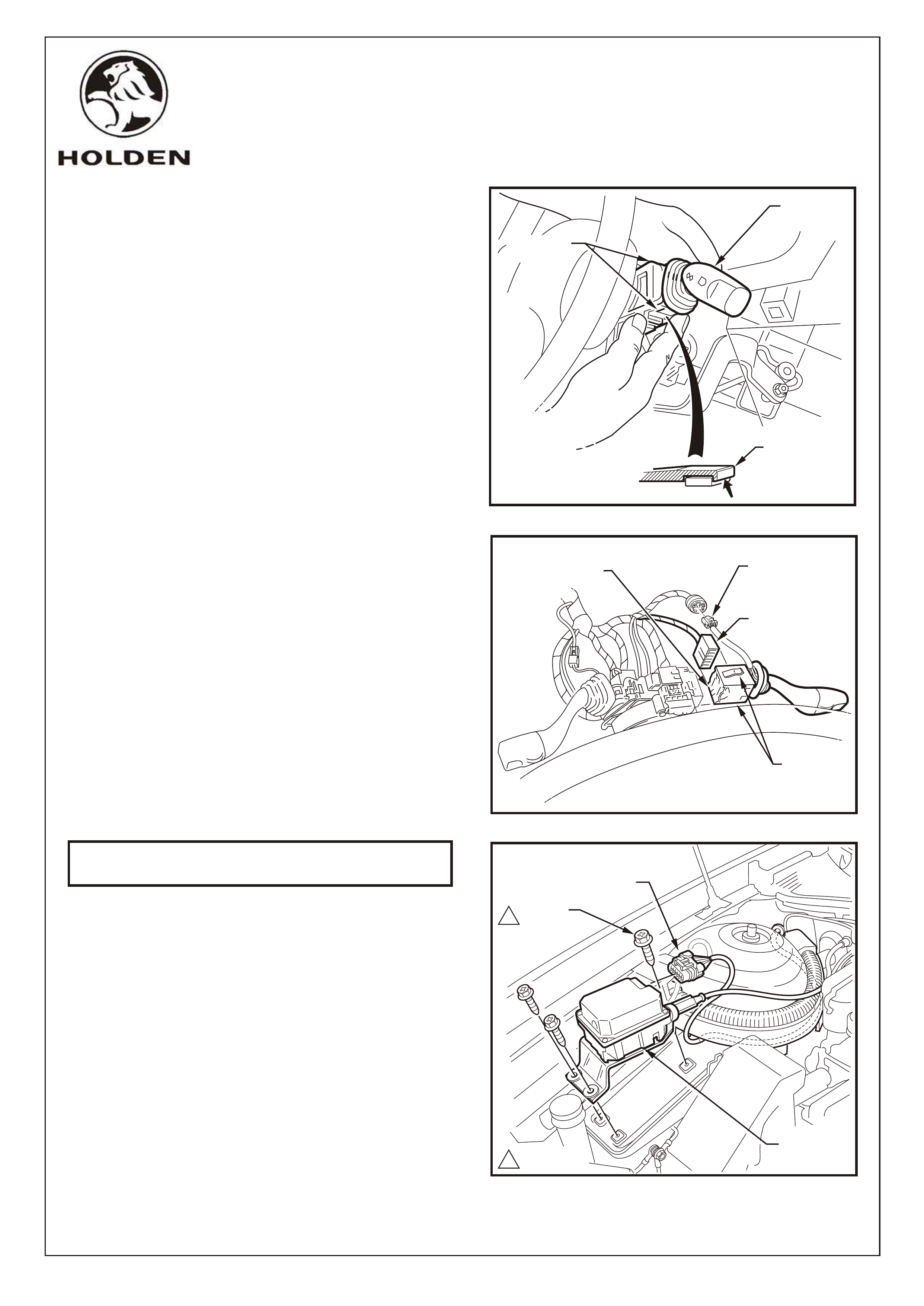
33. Route the brake switch connector and cruise
control release switch connector above the steering
column to the top of the brake pedal (4).
Refer Figure 20 & 24.
34. Fit the cruise control release switch to the mounting
hole in the brake pedal support as follows:
Fit the clip from the cruise control package to the
mounting hole.
Holding the brake pedal in its depressed position,
install the switch into the tubular clip. Push the
switch forward until the switch body locates in the
clip. Refer Figure 24.
NOTE: Audible ‘clicks’ will be heard as the threaded
portion of the switch assembly is pushed into the
tubular clip toward the brake pedal. Pull the brake pedal
fully against the stop until audible ‘click’ sounds can no
longer be heard. (Switch assembly is pushed back out
from the clip to provide correct switch position
adjustment). Depress the brake pedal again and repeat
the above procedure to ensure that the switch
adjustment is correct (no ‘click sounds).
Refer Figure 24.
35. Disconnect the brake switch connector from the
brake switch. Refer Figure 25.
36. Connect the cruise control cabin patch harness
brake switch connector to the brake switch. Refer
Figure 25.
37. Insert the blade terminals into the vehicle brake
switch connector (ensure wire colours are correctly
matched). Refer Figure 25.
38. Insulate the blade terminals into the connector
housing with electrical tape.
39. Attach the cruise control cabin patch harness
release switch connector to the cruise control
release switch. Refer Figure 25.
NOTE: For MANUAL TRANSMISSION vehicles
also refer to Page 18 of these instructions for
additional procedures.
FIGURE 24
CRUISE CONTROL
RELEASE SWITCH
BRAKE
PEDAL
SUPPORT
CLIP
CRUISE
CONTROL
PATCH
HARNESS
EXISTING
WIRING
HARNESS
BLADE
TERMINALS
BRAKE
SWITCH
BRAKE
SWITCH
CONNECTOR
FIGURE 25
CRUISE CONTROL
RELEASE SWITCH
G673
FD1069
11MA03
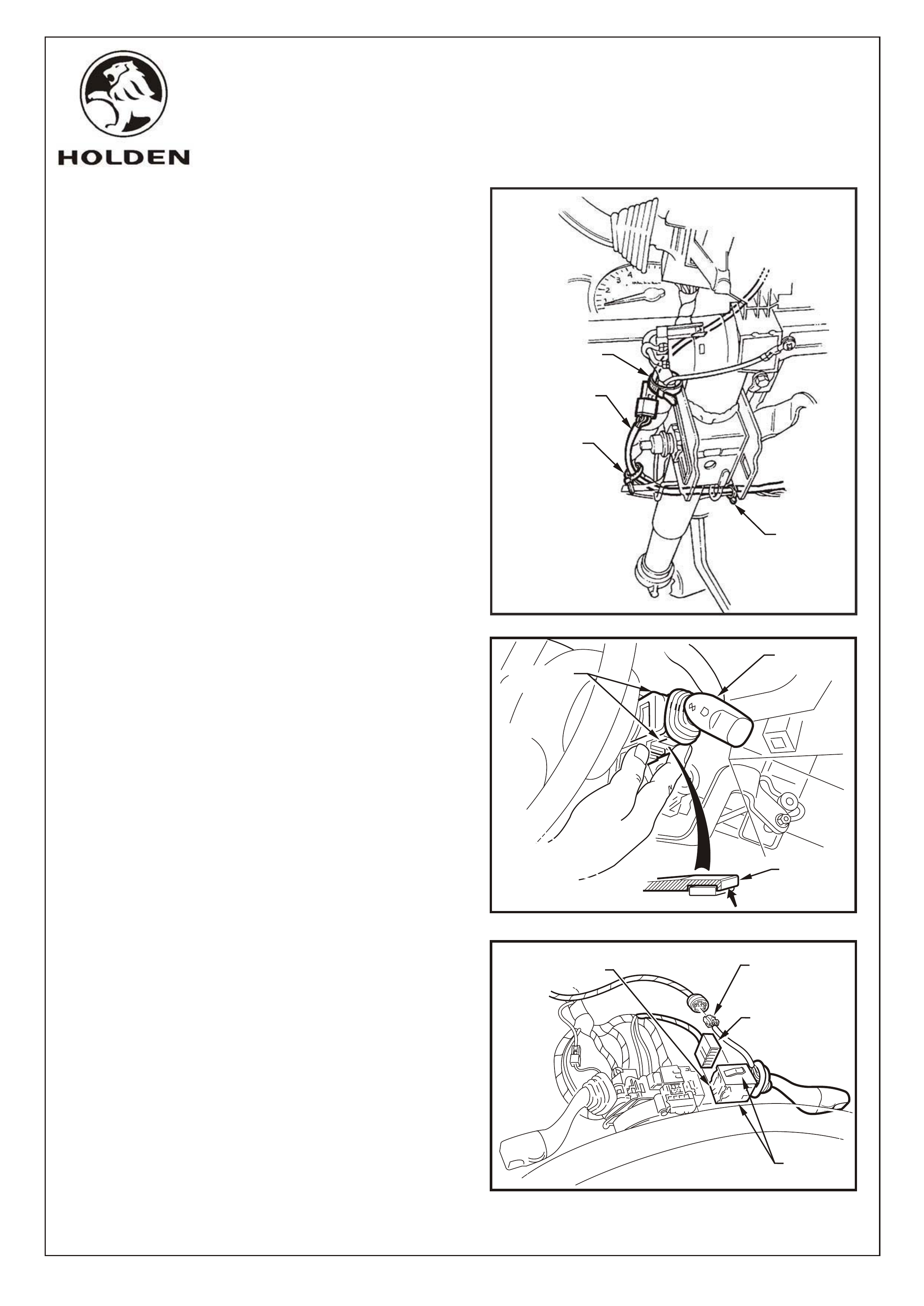
40. Route the cabin patch harness up alongside the
steering column wiring harness to the indicator stalk
switch (5). Refer Figures 26 & 28.
41. Depress the retaining tangs on the turn switch stalk
assembly and pull the assembly away from the
steering column. Refer Figure 27.
42. Depress the wiring harness connector tangs and
pull the connector from the switch assembly.
Remove the turn signal assembly and replace with
the cruise control/indicator switch assembly from
the cruise control package.
Connect the cruise control patch harness connector
and indicator switch connector to the cruise control/
indicator switch assembly.
Refer Figure 28.
43. Secure patch harness from fuse panel to stalk
switch with supplied tie straps. Refer Figure 28.
COPYRIGHT
Page 12 of 19
HOLDEN SERVICE PARTS OPERATIONS
Reproduction in whole or part
prohibited without written approval
Division of HOLDEN Ltd ACN 006 893 232
CRUISE CONTROL
PATCH HARNESS
TIE STRAP
TIE STRAP
TIE STRAP
FIGURE 26
FIGURE 28
RH INDICATOR
SWITCH
CONNECTOR
CRUISE CONTROL
STALK
CONNECTOR
SWITCH
RETAINING
TANGS
FIGURE 27
RETAINING
TANGS
RETAINING
TANG
SWITCH
ASSEMBLY
RH INDICATOR
SWITCH ASSEMBLY
G673
FD1069
11MA03
COPYRIGHT
Page 13 of 19
HOLDEN SERVICE PARTS OPERATIONS
Reproduction in whole or part
prohibited without written approval
Division of HOLDEN Ltd ACN 006 893 232
44. Route the remaining section of the cruise control
cabin harness (two 24 pin connectors) over the
steering column, behind the centre console, beneath
the HVAC unit, to the left-hand side kick panel.
45. Unclip the main wiring harness connector from the
retaining bracket and disconnect from the power train
harness connector. Refer Figure 29.
46. Connect the corresponding connectors on the cruise
control cabin patch harness to the main wiring harness
connector and the powertrain harness connector.
Refer Figure 29.
47. Clip the main wiring harness connector back into the
retaining bracket. Refer Figure 29.
48. Cable tie cruise control cabin patch harness securely
as indicated below. Refer Figure 30.
FIGURE 29
POWERTRAIN
HARNESS
CONNECTOR
MAIN WIRING
HARNESS
CONNECTOR
RETAINING
BRACKET
CRUISE CONTROL
CABIN PATCH
HARNESS
FIGURE 30
POWERTRAIN
HARNESS
CONNECTOR
CABLE TIE
INSTRUMENT
CLUSTER
HARNESS
INSTRUMENT
CLUSTER
CONNECTOR
GLOVEBOX SUPPORT
PANEL
CABLE TIE
CRUISE CONTROL
CABIN PATCH
HARNESS
CABLE TIE
CABLE TIE
CRUISE CONTROL
CABIN PATCH
HARNESS
CABLE TIE
A
B
C
B
C
A
G673
FD1069
11MA03
COPYRIGHT
Page 14 of 19
HOLDEN SERVICE PARTS OPERATIONS
Reproduction in whole or part
prohibited without written approval
Division of HOLDEN Ltd ACN 006 893 232
FIGURE 31
49. Route the cruise control engine bay patch harness
from the firewall around the strut tower, under the
vehicle harness former to the stepper motor bracket.
Route the earth lead between the stepper motor
bracket and inner fender, to existing body earth stud.
Attach cruise control earth terminal to the body earth
stud with existing terminals and nut.
Refer Figure 31.
Proceed to Step 55.
EARTH TERMINAL
EXISTING NUT
CRUISE CONTROL
STEPPER MOTOR
CONNECTOR
STEPPER MOTOR
BRACKET
CRUISE CONTROL
ENGINE BAY
HARNESS
STUD
IMPORTANT: Steps 50 to 54 apply only to vehicles which have cruise control wiring incorporated in the
existing vehicle wiring as determined by the presence of an existing stepper motor connector. Refer Figure 4.
CLIP
ATTACH
CONNECTOR
TO CRUISE
CONTROL
RELEASE
SWITCH
BRAKE
PEDAL
CRUISE CONTROL
RELEASE SWITCH
FIGURE 32
50. Fit the clip from the cruise control package to the
mounting hole of the brake pedal support. Refer
Figure 32.
51. Untape the connector from the wiring harness and
connect to the cruise control release switch.
52. Holding the brake pedal in the depressed position,
install the switch into the tubular clip. Push the
switch forward until the switch body locates in the
clip.
Refer Figure 32.
NOTE: Audible 'clicks' will be heard as the threaded
portion of switch assembly is pushed into the tubular
clip toward the brake pedal. Pull brake pedal fully
against stop until audible 'click' sounds can no longer
be heard. (Switch assembly is pushed back out from
the clip to provide correct switch position adjustment).
Depress the brake pedal again and repeat above
procedure to ensure that the switch adjustment is
correct (no 'click' sounds).
G673
FD1069
11MA03
COPYRIGHT
Page 15 of 19
HOLDEN SERVICE PARTS OPERATIONS
Reproduction in whole or part
prohibited without written approval
Division of HOLDEN Ltd ACN 006 893 232
53. Depress the retaining tangs on the switch assembly
and pull the assembly away from the steering column.
Refer Figure 33.
54. Depress the wiring harness connector tangs and
pull the connector from the switch assembly.
Remove the turn signal assembly and replace with
the cruise control/indicator switch assembly from
the cruise control package.
Connect the cruise control patch harness connector
and indicator switch connector to the cruise control/
indicator switch assembly.
Refer Figure 34.
IMPORTANT: Steps 55 onwards applies to all
vehicles.
55. Install the stepper motor to the stepper motor
mounting bracket using the 3 screws supplied
and tighten to specified torque.
Refer Figure 35.
56. Attach the connector from the cruise control engine
bay patch harness or the existing harness to the
stepper motor. Refer Figure 35.
RH INDICATOR
SWITCH ASSEMBLY
RH INDICATOR
SWITCH
CONNECTOR
CRUISE CONTROL
STALK
CONNECTOR
SWITCH
RETAINING
TANGS
FIGURE 34
FIGURE 33
RETAINING
TANGS
RETAINING
TANG
SWITCH
ASSEMBLY
FIGURE 35
STEPPER
MOTOR
SCREW
(3 PLACES)
EXISTING OR
ENGINE BAY PATCH
HARNESS CONNECTOR
12.0 - 5.0 Nm
1
G673
FD1069
11MA03

COPYRIGHT
Page 16 of 19
HOLDEN SERVICE PARTS OPERATIONS
Reproduction in whole or part
prohibited without written approval
Division of HOLDEN Ltd ACN 006 893 232
FIGURE 36
57. Attach the cable to the rear of the stepper motor,
route cable below harness former (fit in existing
clip) and behind brake booster then attach to
engine harness retention clips along edge of
firewall (3 places). Refer Figure 36.
58. Cable to be routed from the last retention clip on
dash panel to the throttle cable bracket in smooth
arc in alignment with the throttle cable.
Refer Figure 36.
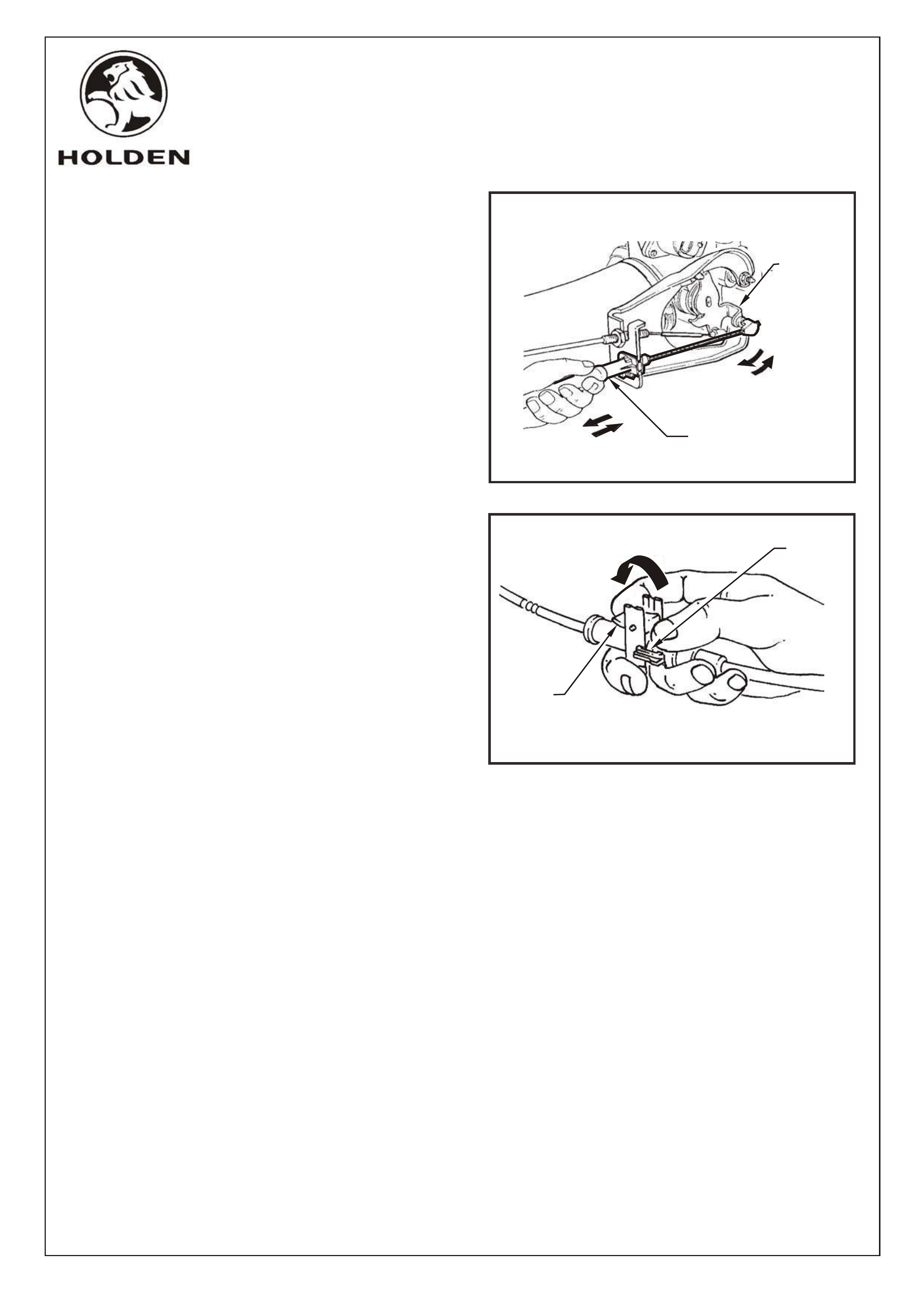
59. Unlock cable adjustment locking lever. Refer
Figure 37.
FIGURE 37
G673
CRUISE
CONTROL
CABLE
THROTTLE
CABLE
A-A
SECTION
(1 PLACE)
WIRING
HARNESS
RETENTION
CLIP
WIPER
MOTOR
HARNESS
(M.W.H.)
POWERTRAIN
WIRING
HARNESS
CRUISE
CONTROL
CABLE
THROTTLE
CABLE
REAR
WASHER
HOSE
(WAGON
ONLY)
(2 PLACES)
B-B
SECTION
WIRING
HARNESS
RETENTION
CLIP
THROTTLE
CABLE
POWERTRAIN
WIRING
HARNESS
REAR
WASHER
HOSE
(WAGON
ONLY)
CRUISE
CONTROL
CABLE
A
A
B
B
B
C
(SERIES II - 1 PLACE)
C-C
SECTION
THROTTLE
CABLE
POWERTRAIN
WIRING HARNESS
CRUISE
CONTROL
CABLE
TIE STRAP
CABLE LOCK
C
BTHROTTLE
CABLE
BRACKET
OUTER
CABLE
LOCK
LOCKING
LEVER
PULL UP
FD1069
11MA03
60. Connect inner cable end to throttle stud then slide
outer cable into throttle bracket. Refer figure 38
COPYRIGHT
Page 17 of 19
HOLDEN SERVICE PARTS OPERATIONS
Reproduction in whole or part
prohibited without written approval
Division of HOLDEN Ltd Can 006 893 232
FIGURE 38
G673
THROTTLE
BODY
VALV E
LEVER
OUTER CABLE
FIGURE 39
OUTER
CABLE
LOCK
LOCKING
LEVER
PUSH DOWN
61. Ensure throttle is in closed position, adjust cruise
control cable, using adjuster, to achieve minimum
slack. Flip adjustment lever to lock cable in
position. Refer figure 39
62. Refit all removed parts noting torques if specified.
63. Re-connect the battery negative lead.
64. Reinstate the audio system by entering the security
code, refer owners manual.
65. Place fitting instructions in the glove box of vehicle.
NOTE: After installation, check operation of cruise
control, (including lamps in instrument panel) in
accordance with Section 12C, Instruments, in VY
Service Information Package (SIP). Any problems may
be corrected using this section of the SIP.
FD1069
11MA03
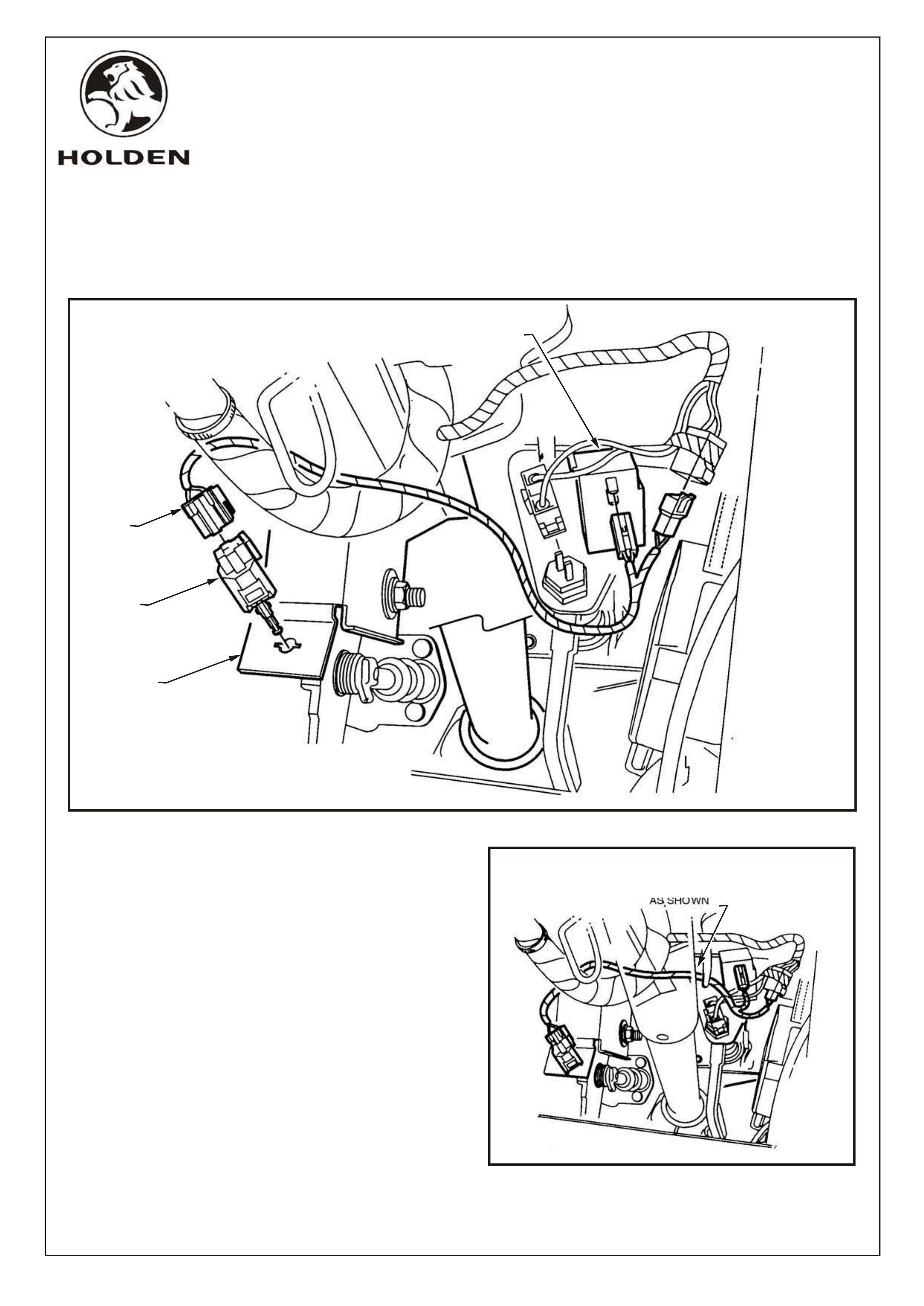
66. Adjust the steering column to the upper position.
67. While depressing the clutch pedal, install the clutch
switch. Refer Figure 40.
68. Rotate the switch 90 degrees to secure in position.
69. Fit the patch harness to the clutch switch. Refer
Figure 40.
70. Route the patch harness over the main wiring harness
and steering column. Refer Figure 41.
71. Fit the patch harness connectors to the cruise control
release switch and main wiring harness connector.
Refer Figure 41.
FITTING INSTRUCTIONS FOR VY
CRUISE CONTROL PACKAGE, MANUAL TRANSMISSION
CLUTCH SWITCH (92077936) AND PATCH HARNESS (92075048)
COPYRIGHT
Page 18 of 19
HOLDEN SERVICE PARTS OPERATIONS
Reproduction in whole or part
prohibited without written approval
Division of HOLDEN Ltd Can 006 893 232
CRUISE CONTROL
RELEASE SWITCH
PATCH
HARNESS
CLUTCH
SWITCH
CLUTCH
PEDAL
BRACKET
PARTIAL STEERING COLUMN
SHOWN FOR CLARITY
ENSURE PATCH HARNESS
IS ROUTED OVER MAIN WIRING
HARNESS AND STEERING COLUMN
AS SHOWN
FIGURE 40
FIGURE 41
G673
FD1069
11MA03

PART NUMBER DESCRIPTION QUANTITY
FITTING INSTRUCTIONS
VY CRUISE CONTROL PACKAGE (92145711),
V6 & SUPERCHARGED V6
PARTS LIST
25336986 STEPPER MOTOR & CABLE ASSEMBLY 1
92138364 BOLT - STEPPER MOTOR TO WHEELHOUSE 3
92066684 PATCH HARNESS - ENGINE BAY 1
92066647 PATCH HARNESS - CABIN 1
92089543 SWITCH - TURN SIGNAL/CRUISE 1
09794682 SWITCH - BRAKE 1
92138622 CLIP - C/CONTROL BRAKE SWITCH MOUNT 1
7436769 STRAP - 220MM 5
SP3516 STRAP - 180MM 7
FD1069 FITTING INSTRUCTIONS BOOKLET 1
FD796 WARRANTY CARD
NOT INCLUDED IN CRUISE CONTROL PACKAGE, BUT MANDATORY TO FIT
TO VEHICLES WITH MANUAL TRANSMISSION (REFER PAGE 18):-
92077936 SWITCH - CLUTCH 1
92075048 PATCH HARNESS - CLUTCH SWITCH 1
COPYRIGHT
Page 19 of 19
HOLDEN SERVICE PARTS OPERATIONS
Reproduction in whole or part
prohibited without written approval
Division of HOLDEN Ltd Can 006 893 232
G673
FD1069
11MA03