FD1071
12SE02
COPYRIGHT
Page 1 of 7
G677
HOLDEN SERVICE PARTS OPERATIONS
Reproduction in whole or part
prohibited without written approval
Division of HOLDEN Ltd ACN 006 893 232
FITTING INSTRUCTIONS FOR
VY POWER ANTENNA KIT,
Part No. 92145378
FITTING INSTRUCTIONS:
1. Disconnect the vehicle battery.
IMPORTANT: Disconnecting the vehicle battery may
impact or damage electrical systems in the Vehicle:-
Body Control Module, Entertainment System, Electric
Sunroof, etc unless correct instructions are followed.
Please contact your Holden Retailer for further
information.
NOTE: To reinstate the audio system, the security code
will be required.
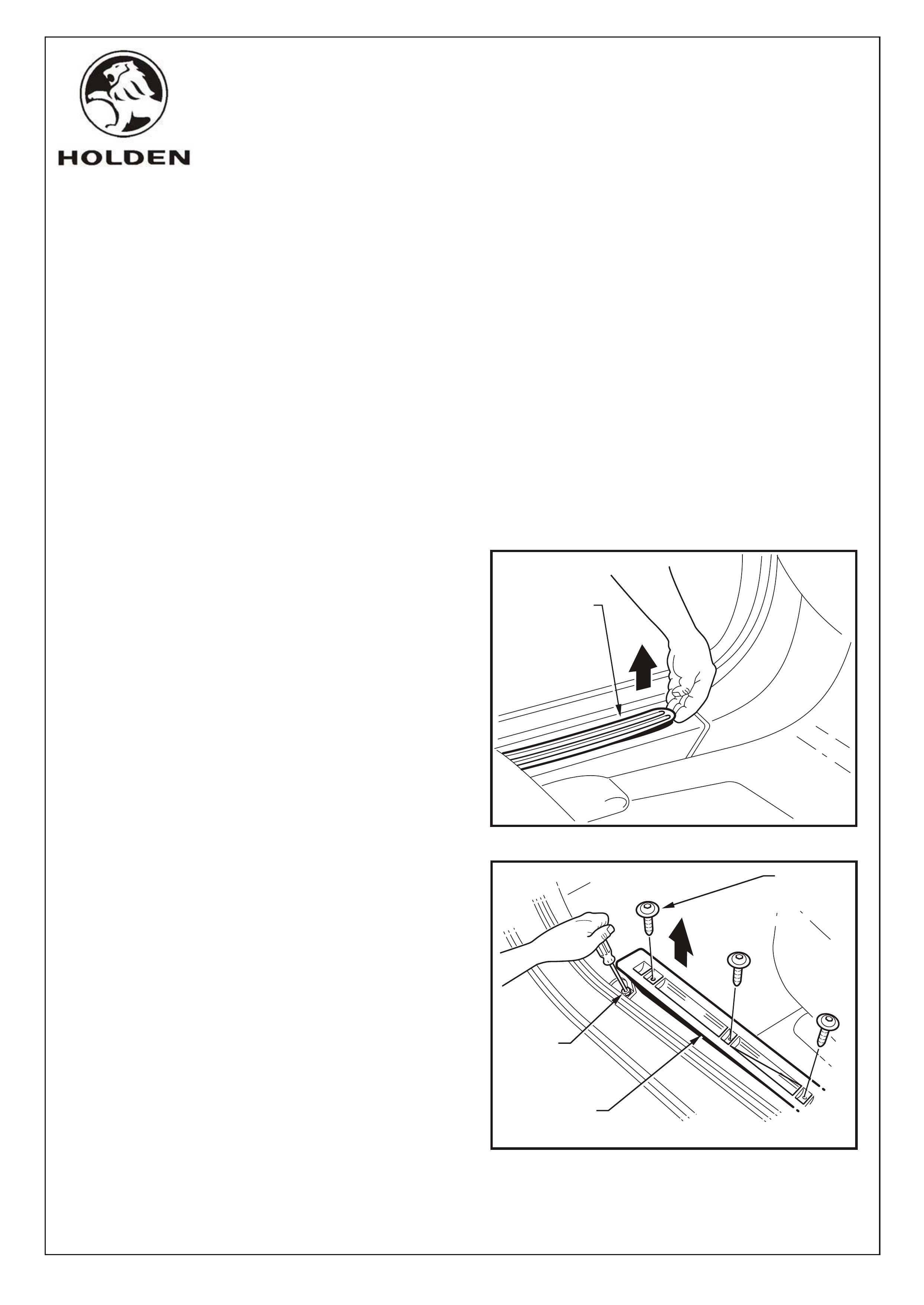
2. Remove the left-hand side rocker panel cover insert.
Refer Figure 1.
3. Remove the front three TORX head screws securing
the left-hand side inner rocker cover panel and loosen
the rear most screw with TORX bit T25. Refer Figure 2.
4. Lift the front of the inner rocker panel cover to gain
access to the screw securing the hinge pillar trim
assembly to the rocker panel. Refer Figure 2.
TOOLS REQUIRED:
Phillips Head Screw Driver, Flat Blade Screwdriver, 10mm
Socket, Torx Bit T25.
FITTING INSTRUCTIONS FOR
VY POWER ANTENNA KIT,
Part No. 92145378
COPYRIGHT
Page 2 of 7
HOLDEN SERVICE PARTS OPERATIONS
Reproduction in whole or part
prohibited without written approval
Division of HOLDEN Ltd ACN 006 893 232
G677
TORX HEAD
SCREW
(3 PLACES)
LEFT-HAND SIDE
ROCKER PANEL
COVER INSERT
FIGURE 1
FIGURE 2
SCREW
INNER ROCKER
PANEL COVER
FD1071
12SE02
COPYRIGHT
Page 3 of 7
HOLDEN SERVICE PARTS OPERATIONS
Reproduction in whole or part
prohibited without written approval
Division of HOLDEN Ltd ACN 006 893 232
G677
FIGURE 4
STEPWELL
LAMP
LEFT-HAND SIDE
INSTRUMENT PANEL
LOWER TRIM PLATE
RETAINING CLIP
(3 PLACES)
A-A
A
A
INSTRUMENT
PANEL
COMPARTMENT
HINGE
BUMPER
STOP
LUG
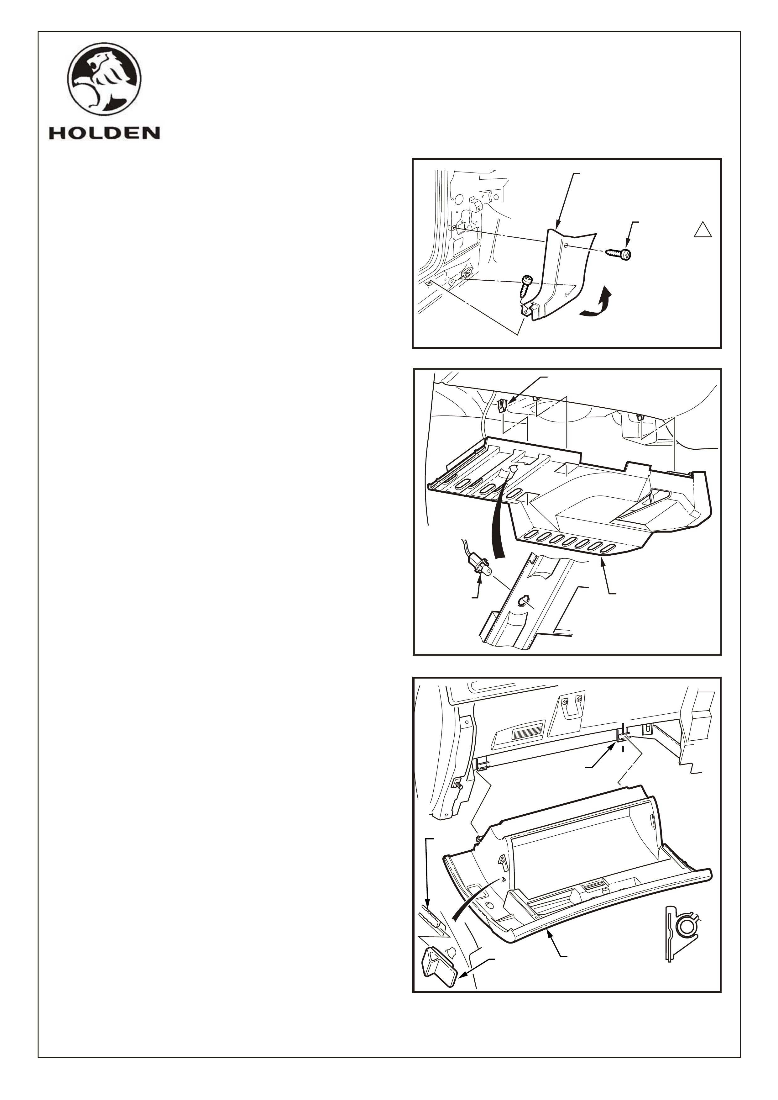
5. Remove the left-hand side hinge pillar trim assembly
as follows:
Remove the two attaching screws from the hinge
pillar trim assembly.
Disengage the hinge pillar trim clip by pulling the
lower edge of the hinge pillar trim assembly up and
away from the sheet metal.
NOTE: When refitting, ensure the outer edge of the
hinge pillar trim assembly engages the door opening
weatherstrip.
Refer Figure 3.
6. Remove the left-hand side instrument panel lower trim
plate assembly as follows:
Grasp the instrument panel lower trim plate
assembly and carefully pull downward to disengage
the retaining clips (3 places).
Lower the plate assembly slightly and if fitted,
remove the stepwell lamp by rotating the socket and
removing from the plate assembly.
Remove the plate assembly.
Refer Figure 4.
7. Remove the instrument compartment assembly as
follows:
Open the instrument compartment assembly.
Using a fine flat-blade screwdriver, flatten the
instrument panel compartment bumper stop each
side and carefully open the compartment assembly
fully.
From the inside of the compartment assembly, push
outwards on the bumper stop and slide the bumper
from the lug. Repeat for the opposite side.
Close the compartment assembly half way and
grasping each side pull rearward to disengage the
compartment assembly from each instrument panel
compartment hinge.
Refer Figure 5.
NOTE: Take care when disengaging the hinges as
removing the compartment assembly on the wrong
angle may cause damage.
FIGURE 5
1
SCREW
(2 PLACES)
LEFT-HAND SIDE
HINGE PILLAR TRIM
ASSEMBLY
FIGURE 3
FD1071
12SE02
COPYRIGHT
Page 4 of 7
HOLDEN SERVICE PARTS OPERATIONS
Reproduction in whole or part
prohibited without written approval
Division of HOLDEN Ltd ACN 006 893 232
G677
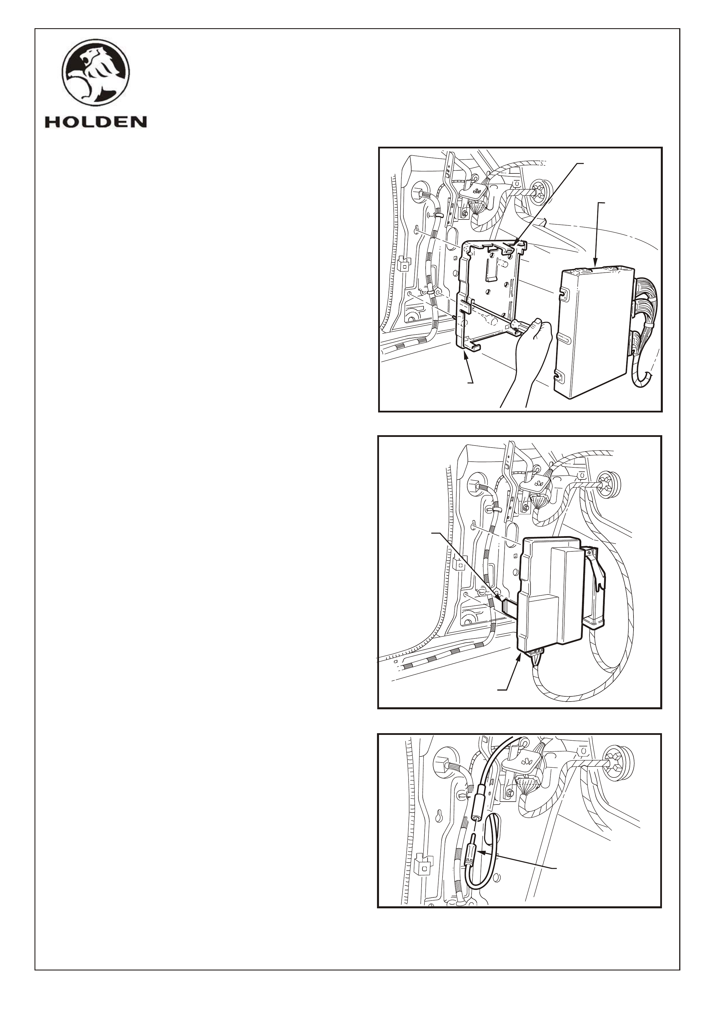
V6 ONLY:
8. Remove the power control module (PCM) as follows:
Leave the wiring harnesses connected to the PCM.
Lift up the mounting bracket to PCM upper retaining
tang, pull the PCM out at the top, then up to remove it
from the mounting bracket.
Remove the PCM mounting bracket by inserting a
screwdriver into the retaining tang slot, lever
screwdriver to release tang. Pull bracket out then
down to release from the cowl panel.
Refer Figure 6.
V8 ONLY:
9. Remove the powertrain interface module (PIM) and
throttle relaxer module (if fitted) as follows:
Leave the wiring harnesses connected to the PIM
and throttle relaxer module.
Press on the bracket locking tang with a flat bladed
screwdriver, then remove both modules from the
shroud panel.
Refer Figure 7.
10. Disconnect the antenna lead connector.
Refer Figure 8.
FIGURE 6
POWER
CONTROL
MODULE
POWER CONTROL
MODULE MOUNTING
BRACKET
FD1071
12SE02
UPPER
RETAINING
TANG
FIGURE 7
POWERTRAIN INTERFACE
MODULE
BRACKET
LOCKING
TANG
ANTENNA LEAD
CONNECTOR
FIGURE 8
COPYRIGHT
Page 5 of 7
HOLDEN SERVICE PARTS OPERATIONS
Reproduction in whole or part
prohibited without written approval
Division of HOLDEN Ltd ACN 006 893 232
G677
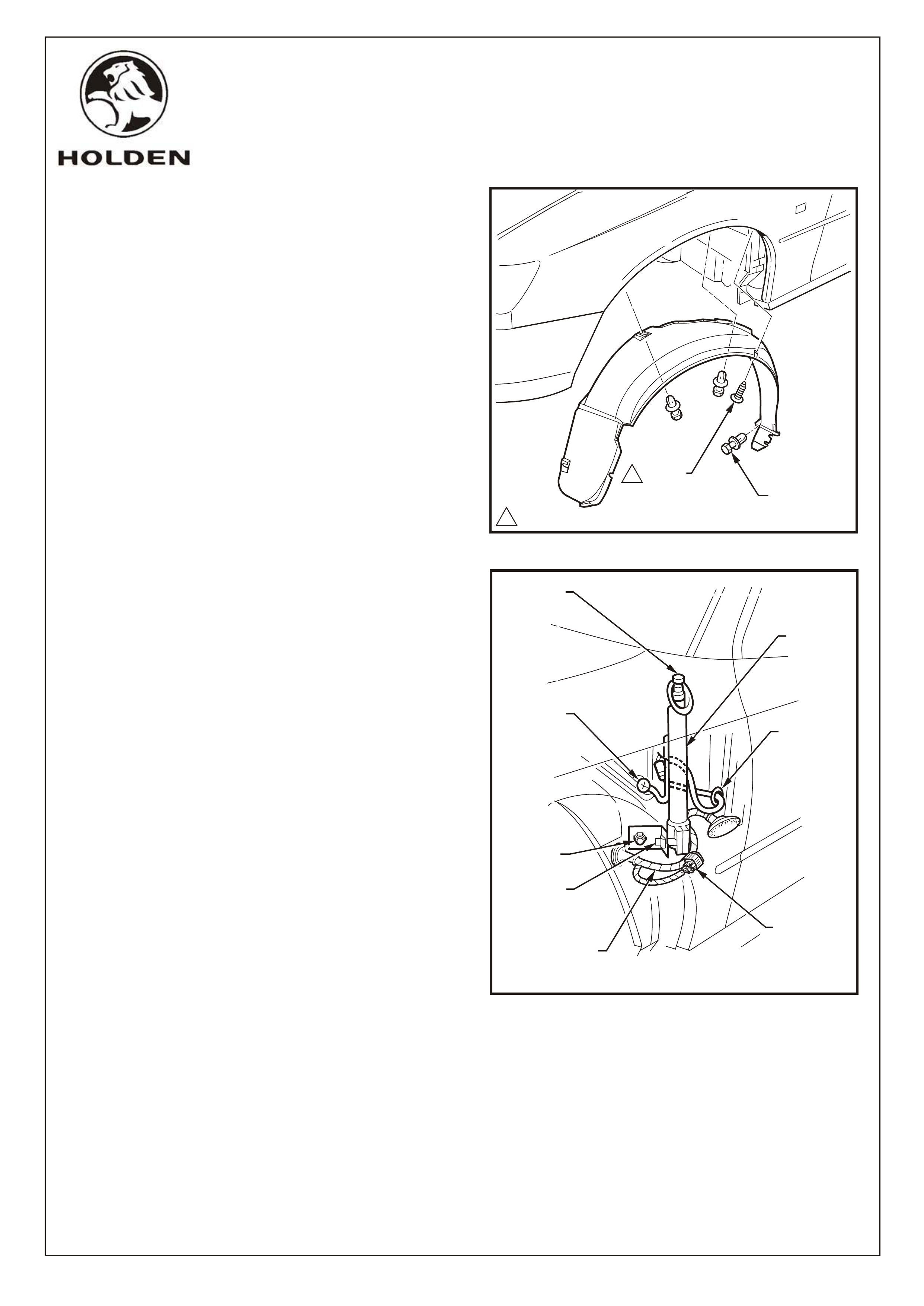
11. Remove the left-hand side front road wheel. Refer to
the vehicle Owners Handbook for the correct jacking
points and removal procedure.
12. Release the rear section of the left-hand side front
wheelhouse liner to gain access to the antenna
assembly as follows:
Remove the screw shown, attaching the liner to the
fender.
Remove the three retainers shown, attaching the
liner to the vehicle.
Carefully pull the rear section of the liner back far
enough to gain access to the antenna.
NOTE: The wheelhouse liner is shown completely
removed for clarity only.
Refer Figure 9.
13. Remove the manual antenna assembly as follows:
Push the antenna mast down to the fully retracted
position.
Remove the screw (retain) connecting the ground
braid to the inner fender ground terminal.
While supporting the antenna, remove the M8 bolt
(retain) attaching the antenna bracket to the inner
fender panel.
Remove the antenna lead grommet from the inner
fender panel and pull the antenna lead out of the
passenger compartment.
Withdraw the antenna downward through the bezel
and remove, complete with the lead and grommet.
If required, loosen the antenna bracket bolt and
remove the bracket from the antenna.
Refer Figure 10.
14. Locate and untape the existing vehicle connector
taped to the front side turn signal lamp wiring harness.
Refer Figure 10.
11.0 - 3.0 Nm
SCREW
RETAINER
(3 PLACES)
1
FD1071
12SE02
FIGURE 10
GROMMET
ANTENNA
BRACKET
BOLT
M8 BOLT
GROUND
BRAID
RETAINING
SCREW
ANTENNA
ASSEMBLY
ANTENNA
MAST
EXISTING
VEHICLE
CONNECTOR
FRONT SIDE
TURN SIGNAL
LAMP HARNESS
FIGURE 9
COPYRIGHT
Page 6 of 7
HOLDEN SERVICE PARTS OPERATIONS
Reproduction in whole or part
prohibited without written approval
Division of HOLDEN Ltd ACN 006 893 232
G677
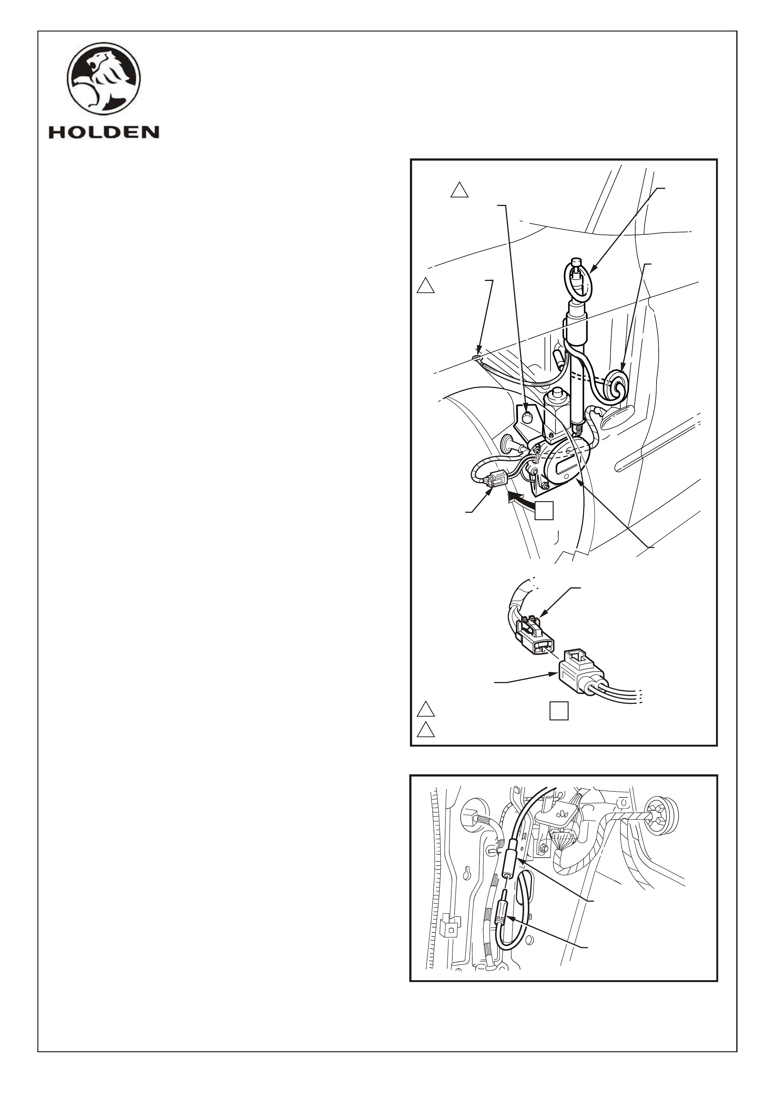
15. Install the power antenna assembly as follows:
Through the left-hand side wheelhouse, fit the
power antenna assembly in position with the
antenna mast locating through the bezel opening.
Secure the antenna support bracket with the original
M8 bolt to the specified torque.
NOTE: Ensure the power antenna is pushed firmly
against the stop in the bezel before tightening the
bracket bolt.
Route the antenna lead through the existing
antenna lead opening.
Fit the antenna lead grommet securely in position.
Secure the ground braid to the panel in the original
position using the original screw. Torque to
specifications.
Connect the power antenna connector to the
existing vehicle connector.
Refer Figure 11.
16. Connect the power antenna lead connector to the radio
antenna lead connector. Refer Figure 12.
FIGURE 11
ORIGINAL
GROUND
BRAID
SCREW
GROMMET
BEZEL
11.0 - 3.0 Nm
2
214.5 - 19.5 Nm
1
POWER
ANTENNA
ASSEMBLY
FD1071
12SE02
FIGURE 12
POWER ANTENNA LEAD
CONNECTOR
RADIO ANTENNA LEAD
CONNECTOR
ORIGINAL POWER ANTENNA
MOUNTING BRACKET
BOLT
EXISTING
VEHICLE
HARNESS
CONNECTOR
POWER
ANTENNA
CONNECTOR
A
A
POWER
ANTENNA
CONNECTOR

PART NUMBER DESCRIPTION QUANTITY
FITTING INSTRUCTIONS
VY POWER ANTENNA (92145378)
PARTS LIST
92047972 POWER ANTENNA (DAA72VT) 1
92096450 BRACKET, MOUNTING (ASSEMBLED TO ANTENNA) 1
FD1071 FITTING INSTRUCTIONS 1
COPYRIGHT
Page 7 of 7
HOLDEN SERVICE PARTS OPERATIONS
Reproduction in whole or part
prohibited without written approval
Division of HOLDEN Ltd Can 006 893 232
G677
17. Check the power antenna and audio system for correct
operation.
Ensure the outer edge of the inner rocker panel
cover engages the door opening weatherstrip.
19. Re-connect the battery negative lead.
20. Reinstate the audio system by entering the security
code, refer to owners manual.
21. Place fitting instructions in glovebox.
18. Refit all removed parts in the reverse order of removal
noting the following:
Torque fasteners to specified torque.
FD1071
12SE02