
FD1072
30AU02
COPYRIGHT
Page 1 of 11
G678
HOLDEN SERVICE PARTS OPERATIONS
Reproduction in whole or part
prohibited without written approval
Division of HOLDEN Ltd ACN 006 893 232
FITTING INSTRUCTIONS FOR
VY ANTI-THEFT ALARM KIT
Part No. 92144974
DEALER
FIT
ONLY
FITTING INSTRUCTIONS:
1. Disconnect the vehicle battery.
IMPORTANT: Disconnect both positive and negative
battery terminals and wait a minimum of 10 seconds
before beginning work on the vehicle to ensure the
airbag/s are disabled.
IMPORTANT: Disconnecting the vehicle battery may
impact or damage electrical systems in the Vehicle:-
Body Control Module, Entertainment System, Electric
Sunroof, etc unless correct instructions are followed.
Please contact your Holden Retailer for further
information.
NOTE: To reinstate the audio system, the security code
will be required.
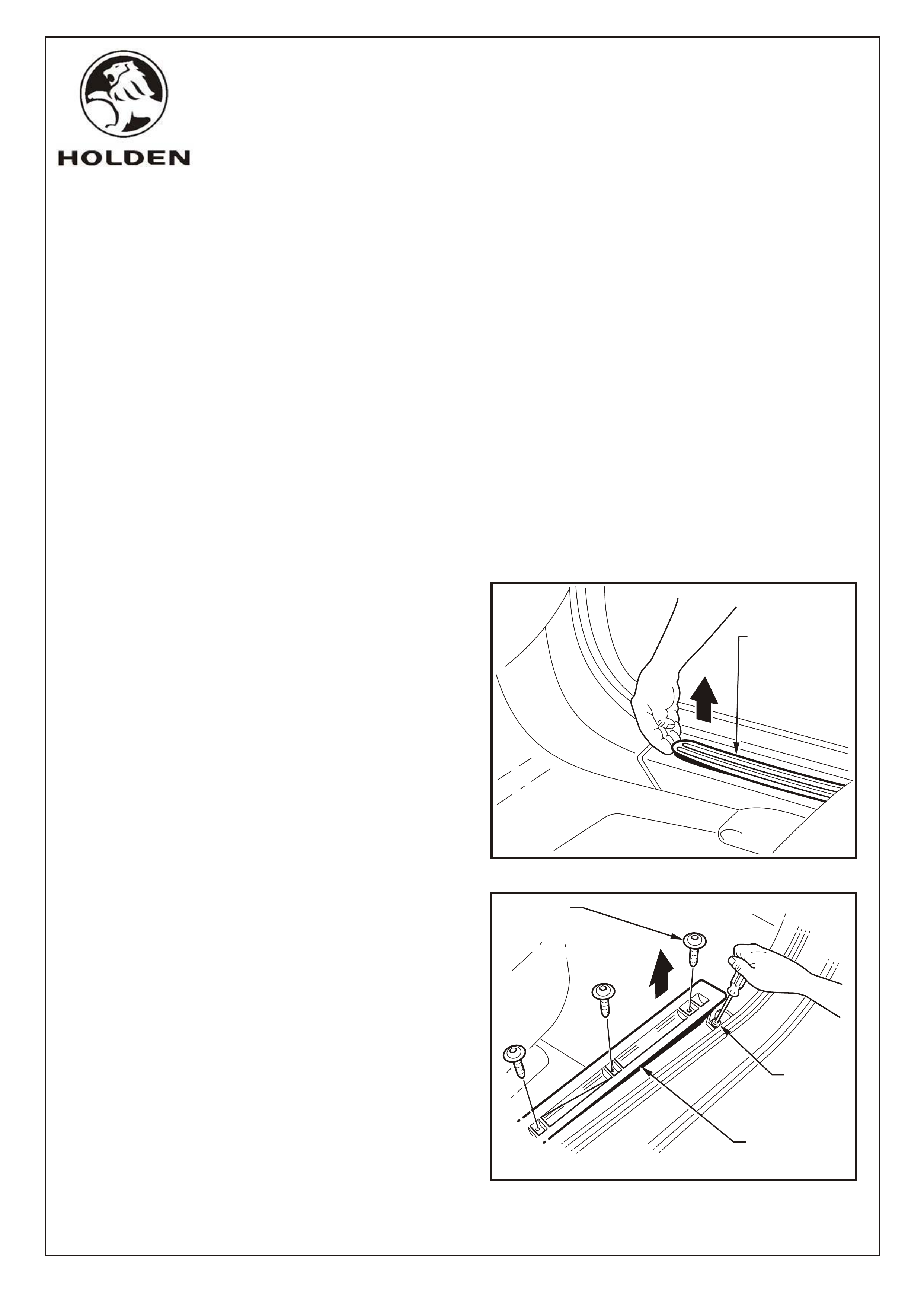
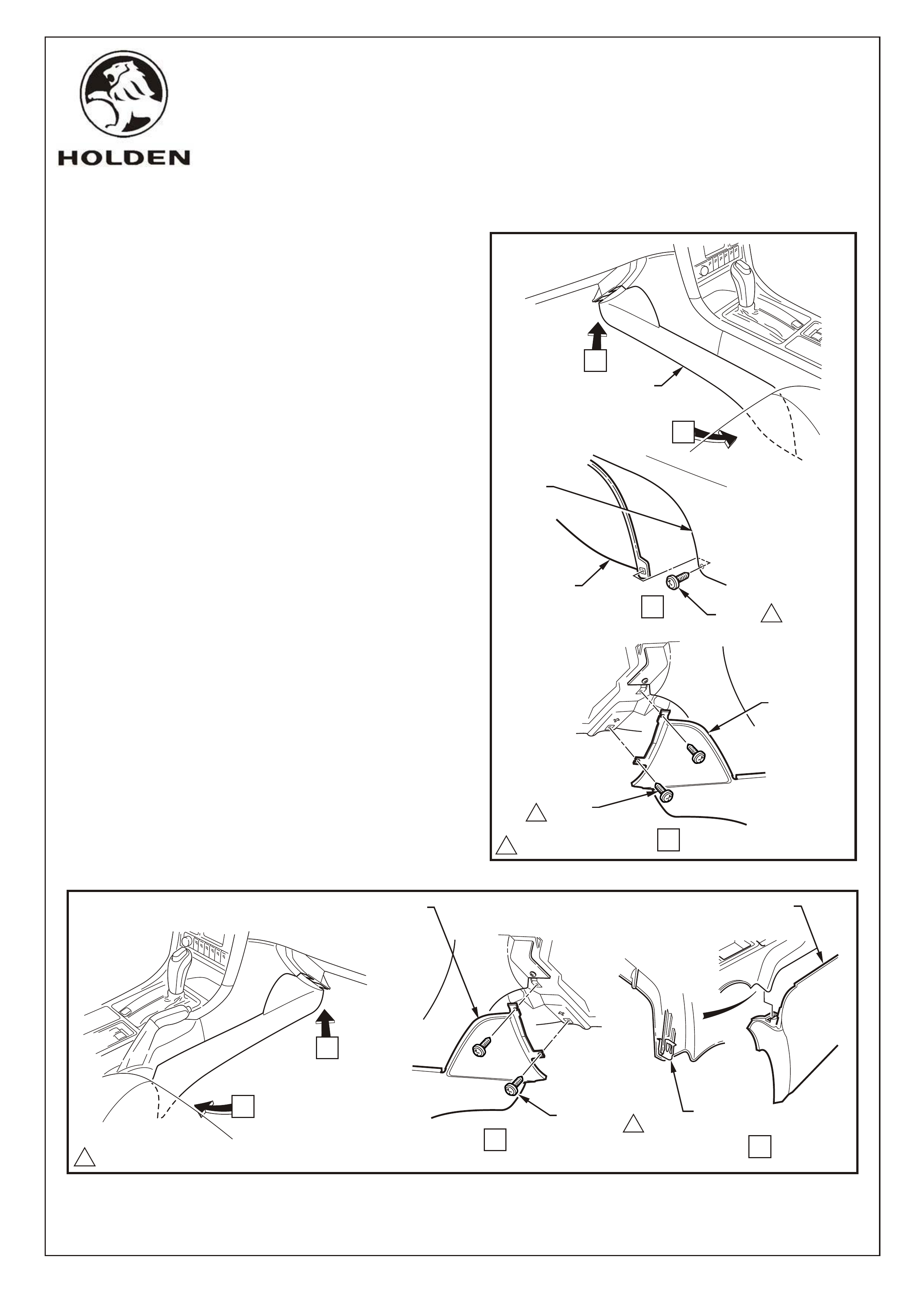
2. Remove the right-hand side rocker panel cover insert.
Refer Figure 1.
3. Remove the front three TORX head screws securing
the right-hand side inner rocker cover panel and loosen
the rear most screw with TORX bit T25. Refer Figure 2.
4. Lift the front of the inner rocker panel cover to gain
access to the screw securing the hinge pillar trim
assembly to the rocker panel. Refer Figure 2.
TOOLS REQUIRED:
Phillips Head Screw Driver, Flat Blade Screwdriver, 10mm
Socket, Torx Bit T25
FITTING INSTRUCTIONS FOR
VY ANTI-THEFT ALARM KIT,
Part No. 92145378
COPYRIGHT
Page 2 of 11
HOLDEN SERVICE PARTS OPERATIONS
Reproduction in whole or part
prohibited without written approval
Division of HOLDEN Ltd ACN 006 893 232
FIGURE 1
FD1072
30AU02
G678
RIGHT-HAND SIDE
ROCKER PANEL
COVER INSERT
TORX HEAD
SCREW
(3 PLACES)
FIGURE 2
SCREW
RIGHT-HAND SIDE
INNER ROCKER
PANEL COVER
COPYRIGHT
Page 3 of 11
HOLDEN SERVICE PARTS OPERATIONS
Reproduction in whole or part
prohibited without written approval
Division of HOLDEN Ltd ACN 006 893 232
FITTING INSTRUCTIONS FOR
VY ANTI-THEFT ALARM KIT
FD1072
30AU02
G678
SCREW
(2 PLACES)
1
1
0.7 - 1.0 Nm
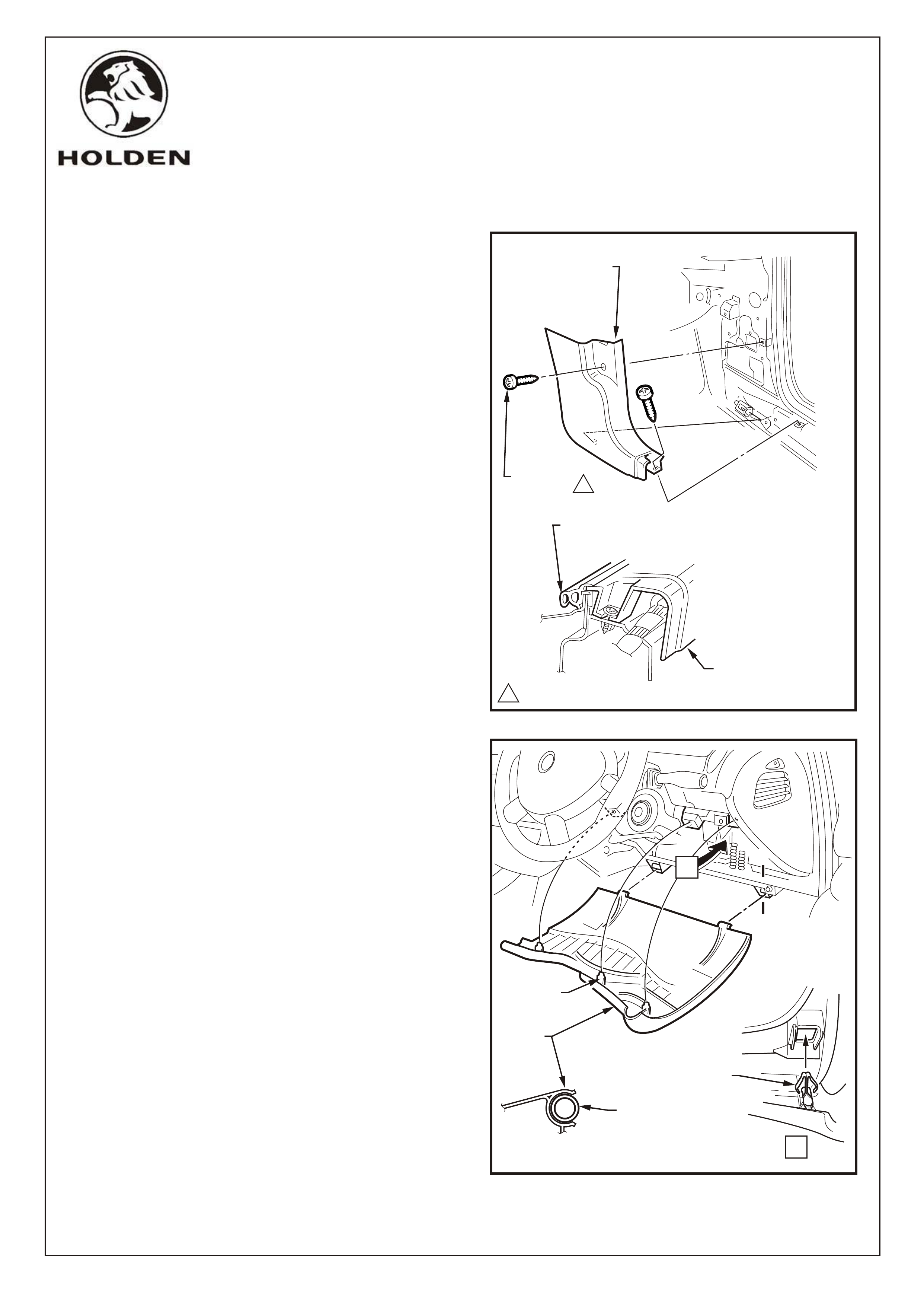
FIGURE 3
RIGHT-HAND SIDE
HINGE PILLAR TRIM
HINGE PILLAR TRIM
DOOR OPENING
WEATHERSTRIP
5. Remove the right hinge pillar trim assembly as follows:
Remove the two attaching screws from the hinge
pillar trim assembly.
Disengage the hinge pillar trim clip by pulling the
lower edge of the hinge pillar trim assembly up and
away from the sheet metal.
NOTE: When refitting, ensure the outer edge of the
hinge pillar trim assembly engages the door opening
weatherstrip.
Refer Figure 3.
6. Remove the instrument panel, lower trim panel
assembly as follows:
Adjust steering wheel to upper most position.
Grasp the upper edge of the instrument panel lower
trim panel assembly and pull outwards to disengage
the three retaining clips.
Swing the panel assembly open.
Holding each side of the panel assembly pull
rearwards to disengage it from the instrument panel
lower trim panel retainer (two places).
Refer Figure 4.
FIGURE 4
LOWER
TRIM
PANEL
A-A
A
A
A
A
RETAINING
CLIP
RETAINING
CLIP
(3 PLACES)
LOWER TRIM
PANEL
RETAINER
(2 PLACES)
COPYRIGHT
Page 4 of 11
HOLDEN SERVICE PARTS OPERATIONS
Reproduction in whole or part
prohibited without written approval
Division of HOLDEN Ltd ACN 006 893 232
FITTING INSTRUCTIONS FOR
VY ANTI-THEFT ALARM KIT
FD1072
30AU02
G678
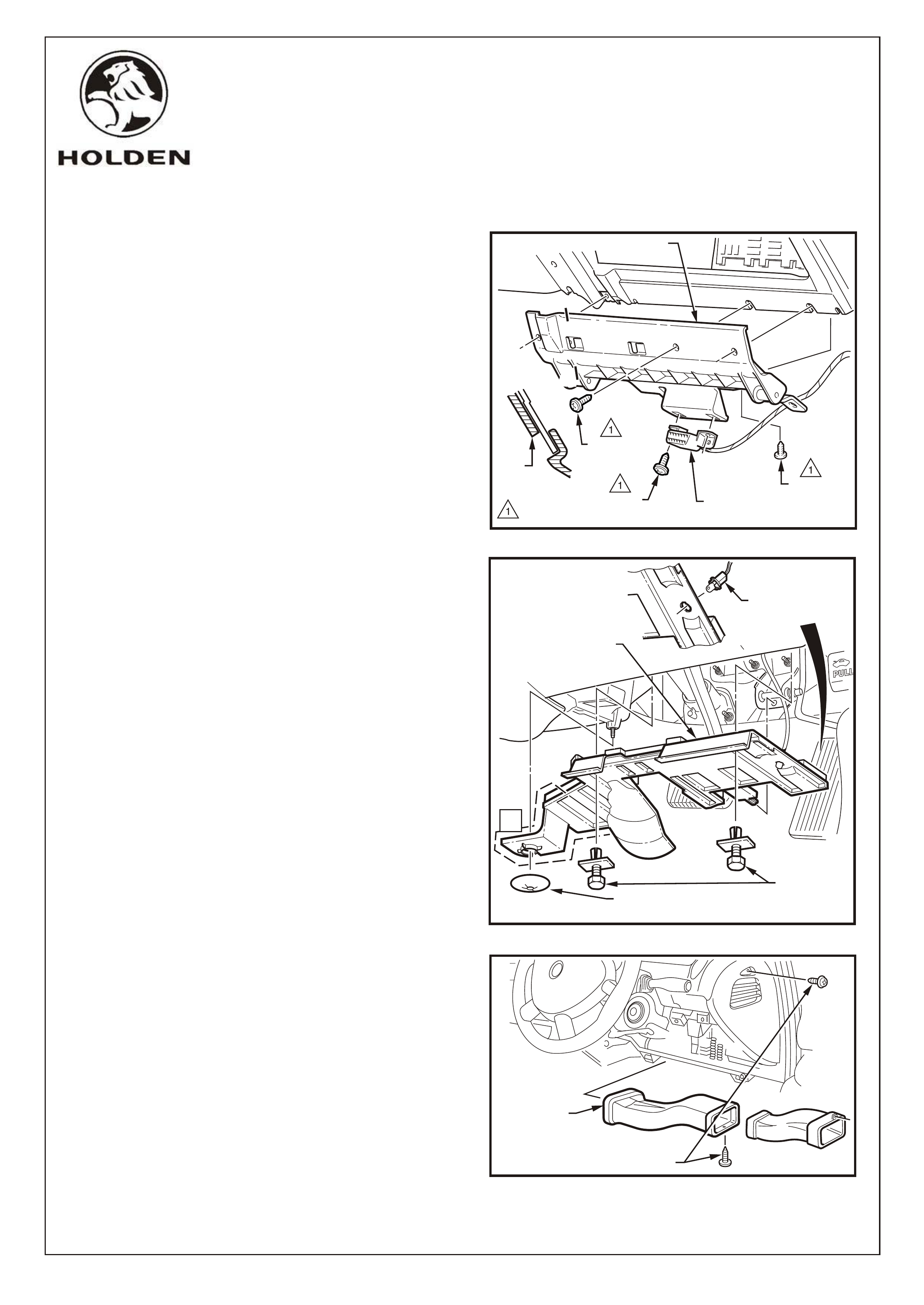
FIGURE 5
1.0 - 3.0 Nm
A
A
A-A DATA LINK
CONNECTOR
SCREW
(2 PLACES)
SCREW
(AIR DUCT)
SCREW
(3 PLACES)
LUG
LOWER TRIM PANEL RETAINER
7. Remove the 2 screws attaching the data link connector
to the instrument panel lower trim panel retainer. Refer
Figure 9.
8. Remove the instrument panel lower trim panel retainer
as follows:
Remove the screw attaching the retainer to the air
duct.
Remove the three screws attaching the retainer to
the instrument panel assembly and the instrument
panel.
Slide the retainer downward to disengage the two
lugs from the instrument panel assembly as shown
at Section A-A and remove the retainer.
Refer Figure 5.
9. Remove the right-hand side instrument panel lower
trim plate assembly as follows:
Remove the retainer attaching the instrument panel
lower trim plate assembly to the HVAC unit
(Automatic Transmission Vehicles only).
NOTE: The area shown A is not present on Manual
Transmission vehicles.
Loosen the screw and remove the retainer (2 places)
attaching the plate assembly to the instrument
panel.
Lower the plate assembly slightly and withdraw the
lug from the pedal bracket.
If fitted, remove the stepwell lamp by rotating the
socket and removing from the plate assembly.
Remove the plate assembly.
Refer Figure 6.
10. Remove the two right-hand side ventilation ducts (2
screws). Refer Figure 7.
FIGURE 6
RETAINER (AUTOMATIC
TRANSMISSION VEHICLES ONLY)
A
RETAINER
(2 PLACES)
INSTRUMENT PANEL
LOWER TRIM PLATE
ASSEMBLY
STEPWELL
LAMP
FIGURE 7
RIGHT-HAND
SIDE
VENTILATION
DUCT
SCREW
COPYRIGHT
Page 5 of 11
HOLDEN SERVICE PARTS OPERATIONS
Reproduction in whole or part
prohibited without written approval
Division of HOLDEN Ltd ACN 006 893 232
FITTING INSTRUCTIONS FOR
VY ANTI-THEFT ALARM KIT
FD1072
30AU02
G678
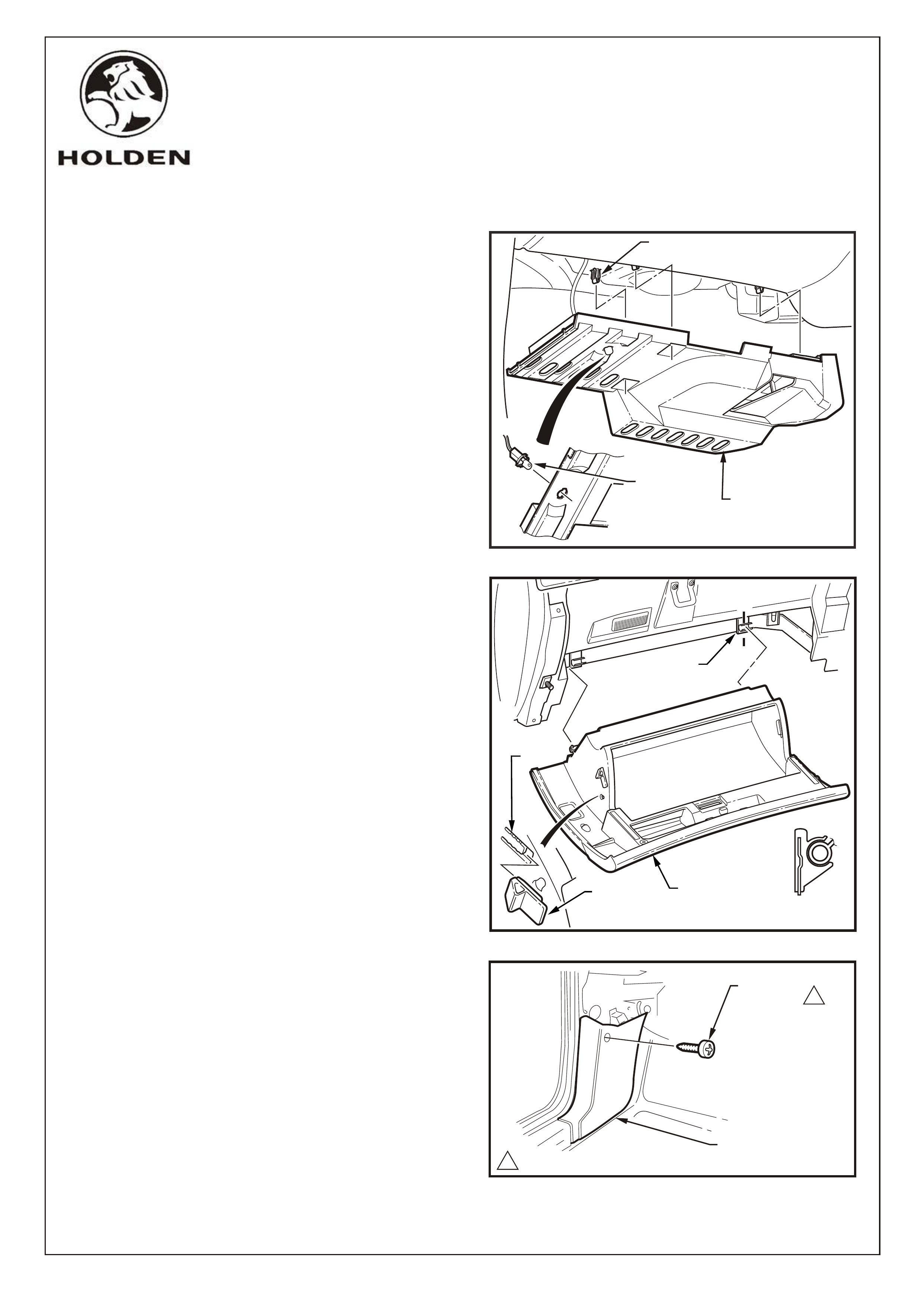
FIGURE 9
STEPWELL
LAMP LEFT-HAND SIDE
INSTRUMENT PANEL
LOWER TRIM PLATE
CLIP
(3 PLACES)
A-A
A
FIGURE 10
A
INSTRUMENT
PANEL
COMPARTMENT
HINGE
BUMPER
STOP
LUG
11. Remove the left-hand side instrument panel lower trim
plate assembly as follows:
Grasp the instrument panel lower trim plate
assembly and carefully pull downward to disengage
the retaining clips (3 places).
Lower the plate assembly slightly and if fitted
remove the stepwell lamp by rotating the socket and
removing from the plate assembly.
Remove the plate assembly.
Refer Figure 8.
12. Remove the instrument compartment assembly as
follows:
Open the instrument compartment assembly.
Using a fine flat-blade screwdriver, flatten the
instrument panel compartment bumper stop each
side and carefully open the compartment assembly
fully.
From the inside of the compartment assembly, push
outwards on the bumper stop and slide the bumper
from the lug. Repeat for the opposite side.
Close the compartment assembly half way and
grasping each side pull rearward to disengage the
compartment assembly from each instrument panel
compartment hinge.
Refer Figure 9.
NOTE: Take care when disengaging the hinges as
removing the compartment assembly on the wrong
angle may cause damage.
13. Remove the left-hand side hinge pillar trim assembly
upper securing screw to allow the carpet and underlay
to be folded back. Refer Figure 10.
14. Remove the firewall grommet from the left-hand side
footwell. Ensure the perimeter of the hole(cabin side) is
clear of sound deadener material.
FIGURE 8
LEFT-HAND SIDE
HINGE PILLAR TRIM
1
SCREW
(2 PLACES)
10.7 - 1.0 Nm
COPYRIGHT
Page 6 of 11
HOLDEN SERVICE PARTS OPERATIONS
Reproduction in whole or part
prohibited without written approval
Division of HOLDEN Ltd ACN 006 893 232
FITTING INSTRUCTIONS FOR
VY ANTI-THEFT ALARM KIT
FD1072
30AU02
G678
FIGURE 11
A
B
1
SCREW
B
1
A
11.0 - 3.0 Nm
FLOOR
CONSOLE
LEFT-HAND
INSTRUMENT
PANEL
LOWER
EXTENSION
SIDE TRIM
INSTRUMENT
PANEL
LOWER
EXTENSION
SIDE TRIM
SCREW
(2 PLACES)
INSTRUMENT
PANEL
LOWER
EXTENSION
SIDE TRIM
15. Remove the left-hand instrument panel lower
extension side trim as follows:
Move the front left hand side seat to its rearmost
position.
Remove the screw attaching the instrument panel
lower extension side trim to the floor console
(View A).
Remove the two screws attaching the side trim to the
instrument panel (View B).
Remove the side trim.
Refer Figure 11.
16. Remove the right-hand instrument panel lower
extension side trim as follows:
Remove the two screws attaching the instrument
panel lower extension side trim to the instrument
panel.
Prise the rear of the trim panel downward to
disengage it form the floor console retaining clip.
Remove the side trim.
Refer Figure 12.
B
A
1
A
B
11.0 - 3.0 Nm
FIGURE 12
RIGHT-HAND INSTRUMENT
PANEL LOWER EXTENSION
SIDE TRIM
SCREW
(2 PLACES)
RETAINING
CLIP
RIGHT-HAND INSTRUMENT
PANEL LOWER EXTENSION
SIDE TRIM
COPYRIGHT
Page 7 of 11
HOLDEN SERVICE PARTS OPERATIONS
Reproduction in whole or part
prohibited without written approval
Division of HOLDEN Ltd ACN 006 893 232
FITTING INSTRUCTIONS FOR
VY ANTI-THEFT ALARM KIT
FD1072
30AU02
G678
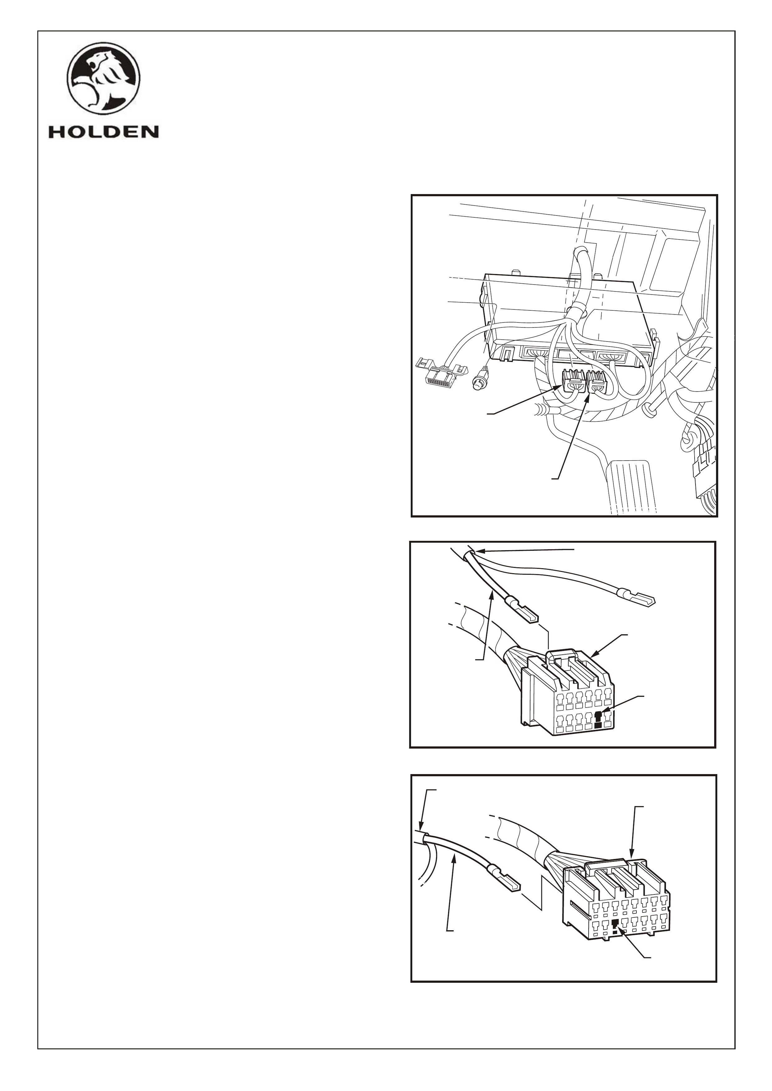
17. Disconnect the 12-Pin and 16-Pin body control module
(BCM) connectors located behind the fuse block.
Refer Figure 13.
18. Remove the locking wedge and insert the RED/WHITE
lead from the anti-theft alarm patch harness
(92144975) into Pin position 11 on the 12-Pin (A15-X2)
BCM connector. Refer Figure 14.
19. Remove the locking wedge and insert the
YELLOW/BLACK lead from the anti-theft patch
harness into pin position 11 on the 16-Pin (A15-X3)
BCM connector. Refer Figure 15.
20. Reconnect the BCM 12-Pin and 16-Pin connectors.
FIGURE 13
BCM 16-PIN
CONNECTOR
(A15-X3)
BCM 12-PIN
CONNECTOR
(A15-X2)
FIGURE 14
FIGURE 15
16
12
7
PIN
POSITION 11
BCM 12-PIN
CONNECTOR
(A15-X2)
RED/WHITE
LEAD
ANTI-THEFT
PATCH HARNESS
1
916
8
BCM 16-PIN
CONNECTOR
(A15-X3)
PIN
POSITION 11
YELLOW/BLACK
LEAD
ANTI-THEFT ALARM
PATCH HARNESS
COPYRIGHT
Page 8 of 11
HOLDEN SERVICE PARTS OPERATIONS
Reproduction in whole or part
prohibited without written approval
Division of HOLDEN Ltd ACN 006 893 232
FITTING INSTRUCTIONS FOR
VY ANTI-THEFT ALARM KIT
FD1072
30AU02
G678
FIGURE 18
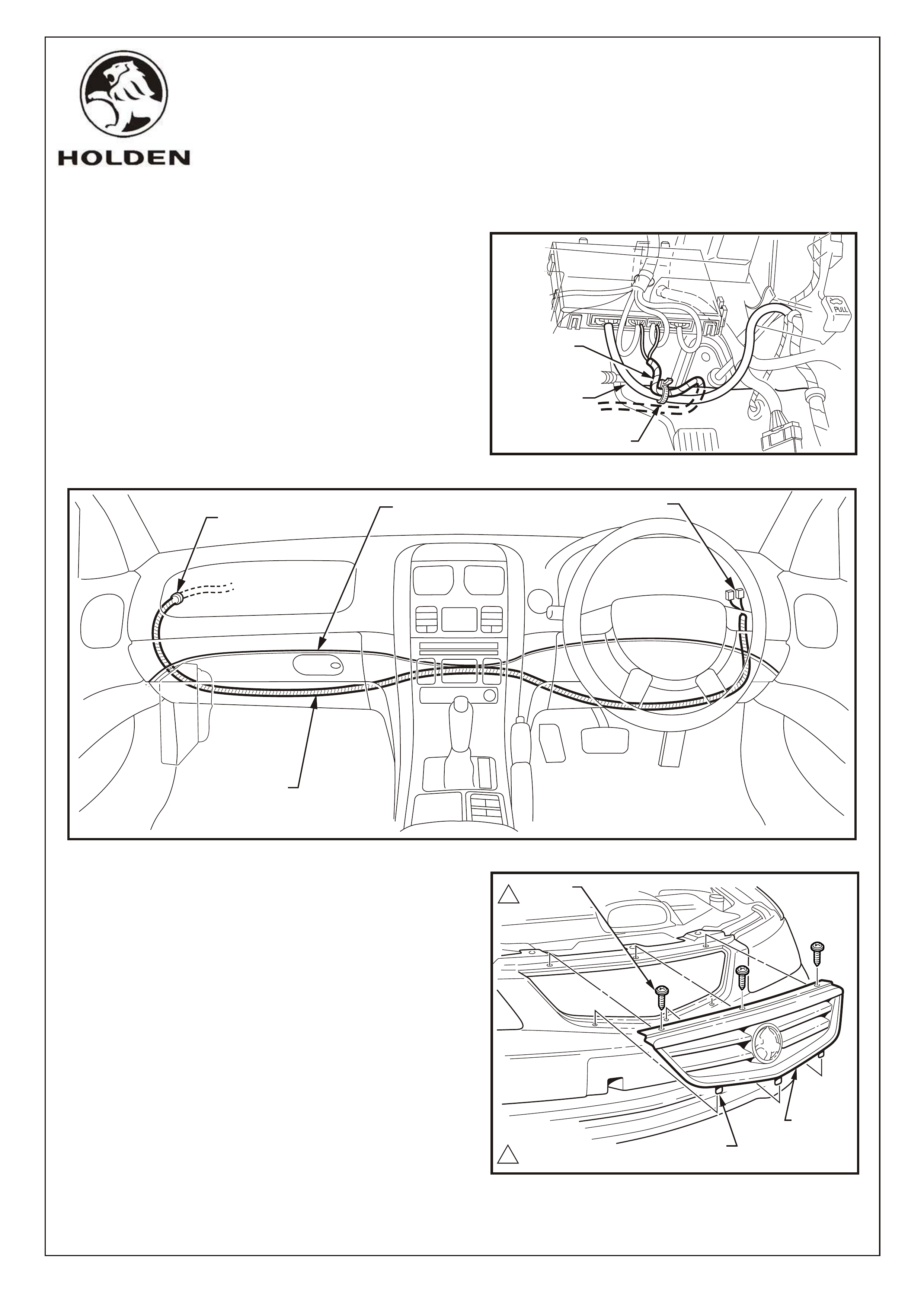
21. Cable tie the anti-theft patch harness to the existing
BCM harness. Refer Figure 16.
22. Route the anti-theft alarm patch harness under the
carpet behind the drivers pedals, behind the HVAC unit
to the left-hand side of the vehicle.
NOTE: Ensure the patch harness is positioned behind
the carpet and is not visible.
Refer Figure 17.
23. Feed the patch harness through the removed grommet
hole into the engine compartment. Secure the
grommet in position and seal with a bead of silicon.
1
1
2.0 - 3.0 Nm
24. Remove the radiator grille assembly as follows:
Remove the three screws attaching the radiator
grille assembly to the bumper fascia.
Tilt the top of the grille assembly forward slightly and
lift it out of the bumper fascia to release the three
pins along the lower edge.
Refer Figure 18.
FIGURE 17
SCREWS
(3 PLACES)
PINS
(3 PLACES)
RADIATOR
GRILLE
ASSEMBLY
BCM CONNECTORS
GROMMET
ANTI-THEFT
PATCH HARNESS
CARPET
FIGURE 16
BCM VEHICLE
HARNESS
ANTI-THEFT
PATCH
HARNESS
CABLE TIE
COPYRIGHT
Page 9 of 11
HOLDEN SERVICE PARTS OPERATIONS
Reproduction in whole or part
prohibited without written approval
Division of HOLDEN Ltd ACN 006 893 232
FITTING INSTRUCTIONS FOR
VY ANTI-THEFT ALARM KIT
FD1072
30AU02
G678
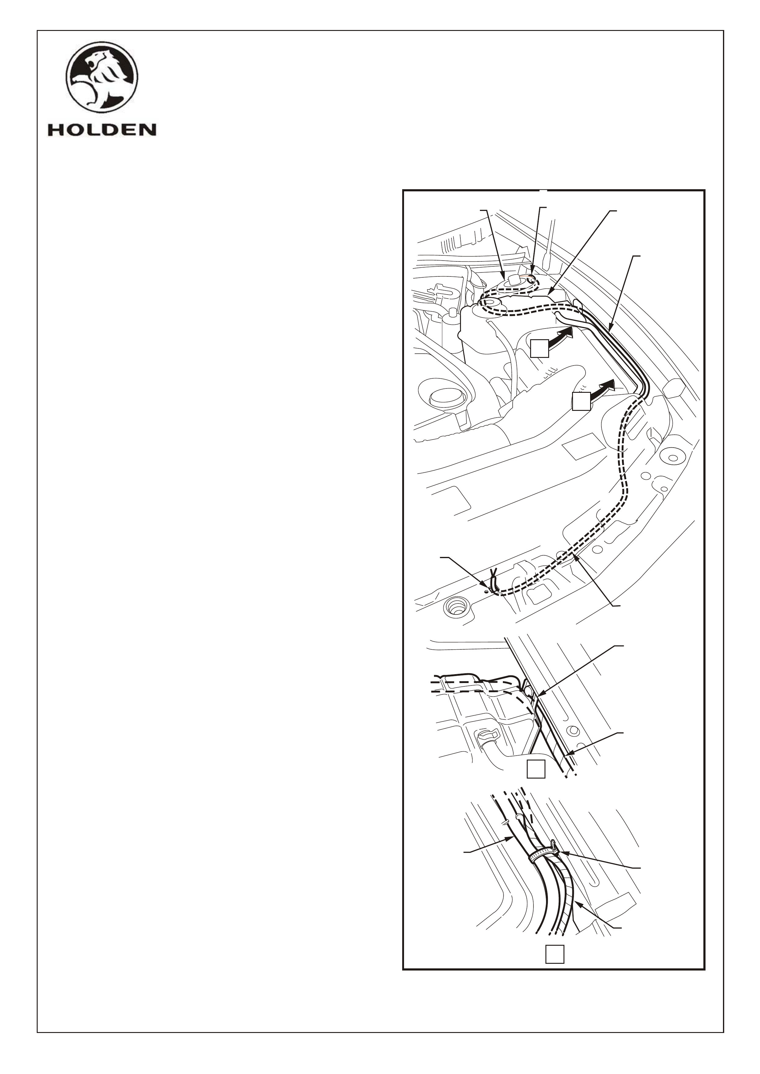
25. Route the anti-theft alarm patch harness to the front
radiator support panel as follows:
Route around the left-hand strut tower between the
radiator overflow reservoir and the tower.
Pass the harness beneath the radiator overflow
reservoir mounting bracket and follow the reservoir
hose to the front of the vehicle.
Route the harness beside the radiator, then below
the radiator support bracket to the existing anti-theft
alarm bonnet switch hole (View A).
Pass wires through the switch hole.
Cable tie the harness to the radiator overflow hose
(View B).
Refer Figure 19.
LEFT-HAND
STRUT TOWER GROMMET RADIATOR
OVERFLOW
RESERVOIR
RADIATOR
OVERFLOW
RESERVOIR
HOSE
ANTI-THEFT
PATCH HARNESS
FIGURE 19
ANTI-THEFT
PATCH HARNESS
RADIATOR
OVERFLOW
RESERVOIR
MOUNTING
BRACKET
A
A
B
SWITCH
BUTTON
HOLE
B
RADIATOR
OVERFLOW
RESERVOIR
HOSE
ANTI-THEFT
PATCH HARNESS
CABLE TIE
COPYRIGHT
Page 10 of 11
HOLDEN SERVICE PARTS OPERATIONS
Reproduction in whole or part
prohibited without written approval
Division of HOLDEN Ltd Can 006 893 232
FITTING INSTRUCTIONS FOR
VY ANTI-THEFT ALARM KIT
FD1072
30AU02
G678
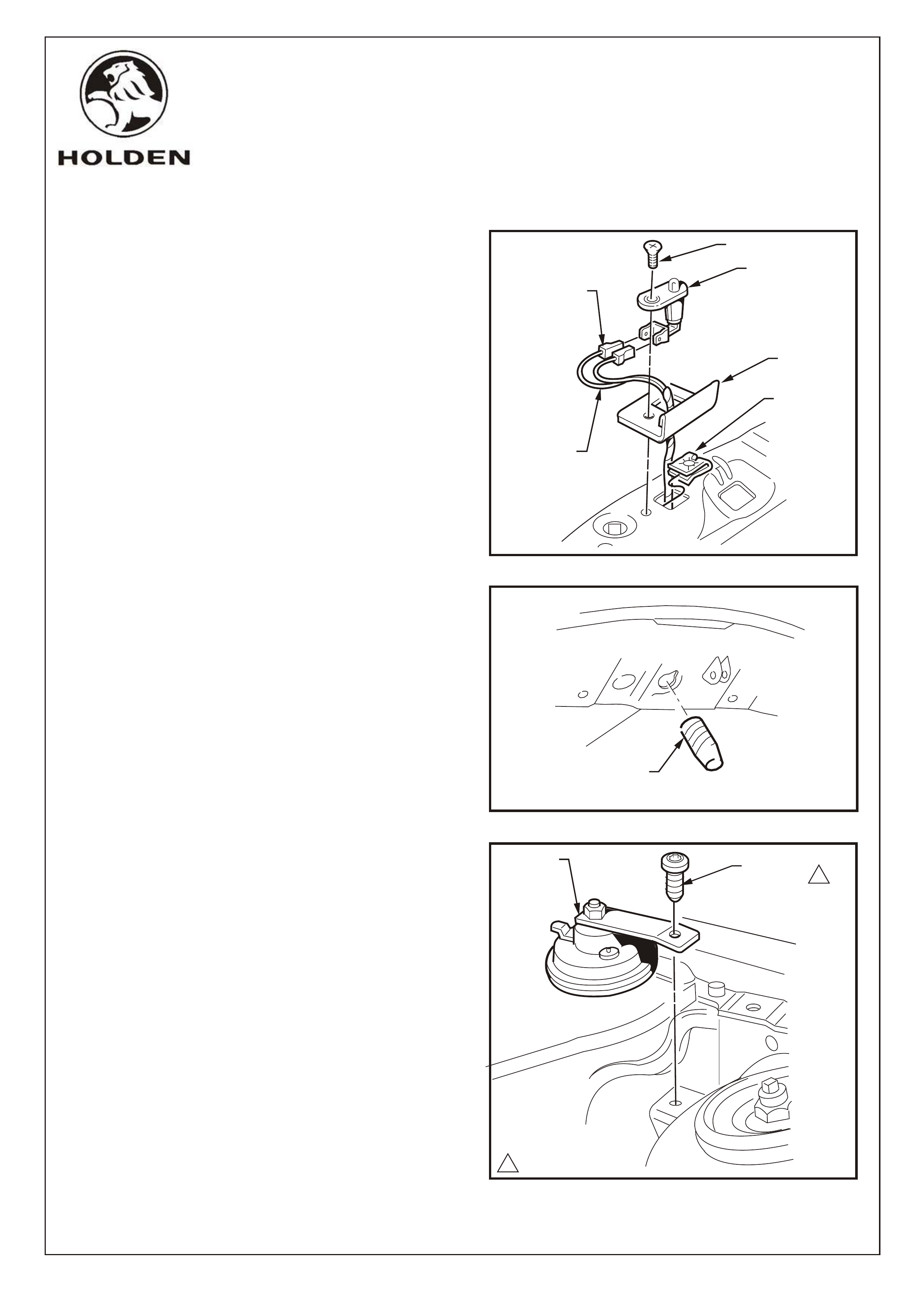
26. Connect the anti-theft harness bonnet switch
connectors to the bonnet switch. Refer Figure 20.
27. Insert the 'J" nut in the bonnet switch hole and fit the
bonnet switch and shield to the radiator support panel
with the screw supplied. Refer Figure 20.
28. Fit the rubber buffer to the bonnet and adjust so that the
bonnet switch is depressed when the bonnet is closed.
Refer Figure 21.
29. Mount the security horn to the bracket on the rear of the
left hand side strut tower using the Torx head screw
supplied. Torque to specifications. Refer Figure 22.
FIGURE 20
FIGURE 21
FIGURE 22
SCREW
BONNET
SWITCH
BONNET
SWITCH
CONNECTOR
SHIELD
"J" NUT
ANTI-THEFT
PATC H
HARNESS
RUBBER
BUFFER
TORX HEAD
SCREW
SECURITY
HORN
14.0 - 6.0 Nm
1
COPYRIGHT
Page 11 of 11
HOLDEN SERVICE PARTS OPERATIONS
Reproduction in whole or part
prohibited without written approval
Division of HOLDEN Ltd Can 006 893 232
FITTING INSTRUCTIONS
VY ANTI-THEFT KIT (92144974)
PARTS LIST
PART NUMBER DESCRIPTION QUANTITY
92144975 WIRING HARNESS 1
92057212 SWITCH 1
92036585 SHIELD 1
11038825 SCREW 1
3466306 BUFFER 1
92056649 SECURITY HORN 1
92138274 TORX HEAD SCREW 1
92138008 J-NUT 1
FD1072 FITTING INSTRUCTIONS 1
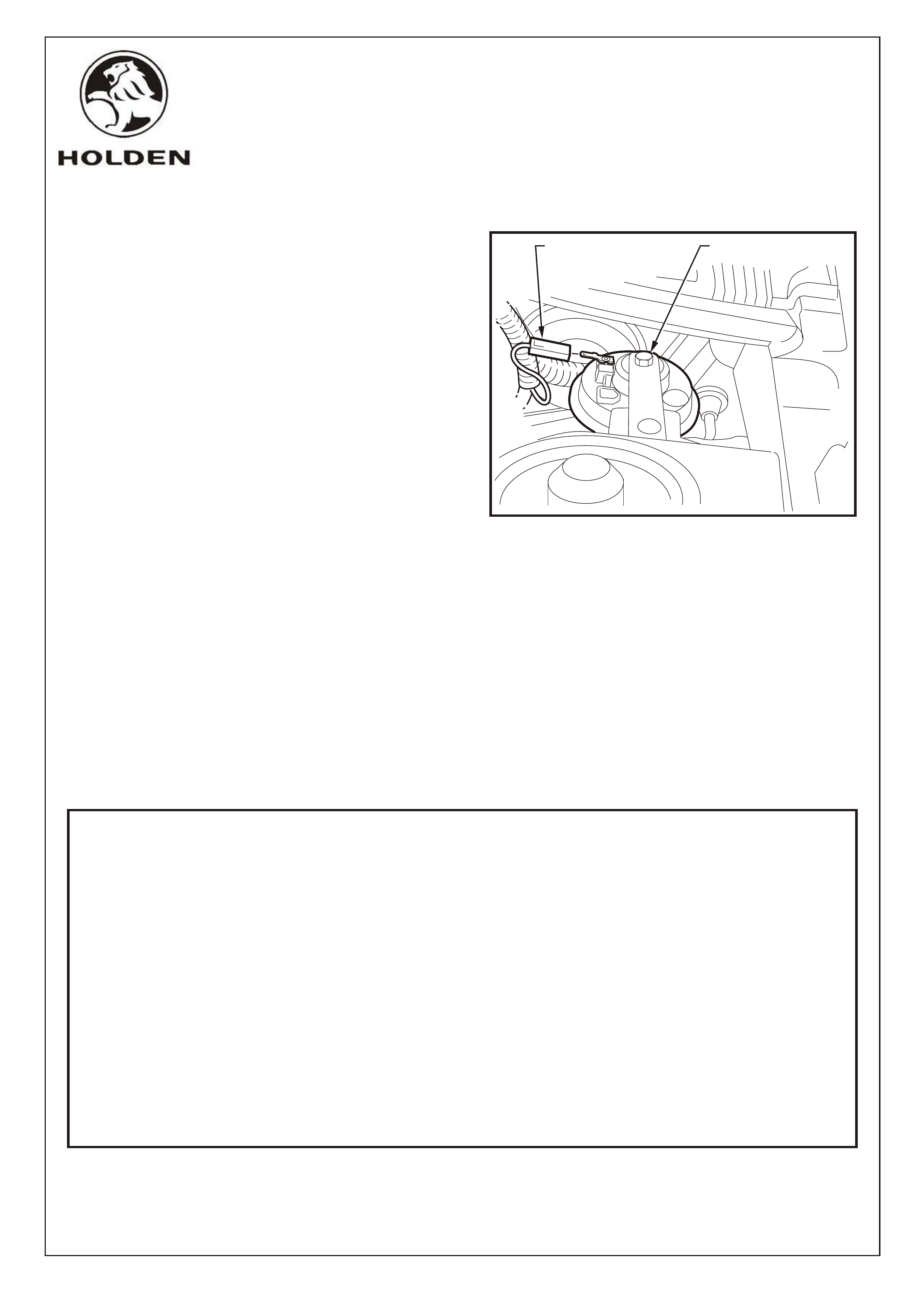
30. Locate the security horn connector on the existing
vehicle wiring harness and connect to the security
horn. Refer Figure 23.
31. Reconnect the battery, refer to notes on Page 2.
32. Using Tech 2, enable the BCM alarm option (refer to the
latest SERVICE INFORMATION on SIP).
33. Test the operation of the alarm system, ie: alarm
triggers off doors and bonnet.
34. Refit all removed parts ensuring fasteners are torqued
to specifications.
35. Place fitting instructions in glovebox.
FITTING INSTRUCTIONS FOR
VY ANTI-THEFT ALARM KIT
FD1072
30AU02
G678
FIGURE 23
EXISTING
VEHICLE
CONNECTOR
SECURITY HORN