Reproduction in whole or part
prohibited without written approval
COPYRIGHT
HOLDEN LTD
Division of HOLDEN Ltd ACN 006 893 232
FD1097
26OCT04
FITTING INSTRUCTIONS
VY NUDGE BAR PACKAGE
Part No. 92146311
Reproduction in whole or part
prohibited without written approval
COPYRIGHT
Page 1 of 2
FITTING INSTRUCTIONS:
Disconnect the battery negative lead.
NOTE: To reinstate the audio system the security code will be required.
1. Disconnect the fog lamps (if fitted).
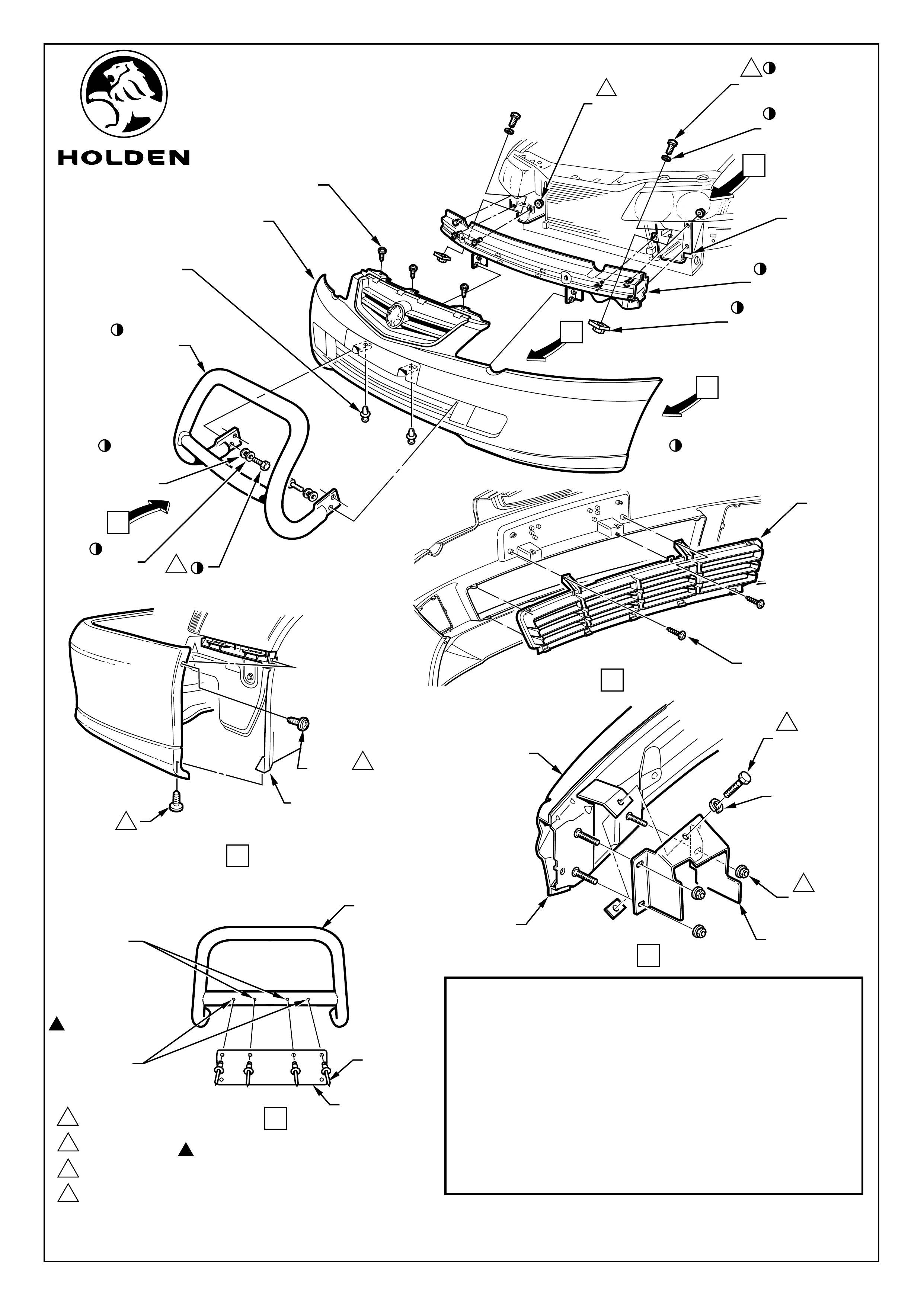
2. Remove the front fascia & disassemble lower mouth fascia grille and place in owners vehicle. Refer Page 2.
Retain all fasteners.
3. Remove the horn/s (one or two depending on model) from the fascia beam.
4. Remove the front fascia support beam from the vehicle, refer page 2.
6. Remove the headlamp assemblies.
7. Install the new front fascia/nudgebar support beam, attach the M8 nuts (6 places) and hand tighten.
8. Install the horn/s to the front fascia/nudge bar support beam.
9. Install the M10 bolt, spring washer and weld nut plate to the front fascia beam bracket and welded tab on the
front fascia/nudge bar support beam. Refer Page 2, View B.
10. Tighten the M8 nuts to 20 - 30Nm (6 places) and the M10 bolts to 45Nm (2 places).
11. Reinstall the headlamp assemblies.
12. Reinstall the front fascia. Refer page 2 .
13. Install the nudge bar onto the front fascia/nudge bar support beam brackets using the M12 bolts, spring
washers and flat washers supplied in the package. Refer Page 2. Tighten the M12 bolts to 75Nm (4 places).
14. Remove the number plate from the front fascia and centralise the upper outermost mounting holes with the
dimples in the nudge bar. Refer page 2, View C.
15. Using the upper outermost number plate holes as a template, drill 4.7mm dia. and attach the number plate
using the rivets supplied (2 places).
16. Again, using the number plate as a template, drill two more 4.7mm dia. holes for the number plate mounting
and fix using the rivets supplied (2 places). Refer Page 2, View C.
17. Reconnect the battery negative lead and reinstate the audio system by entering the security code, refer
owner's manual.
18. Check the alignment of the headlamps and fog lamps (if fitted) and adjust as required, refer Service
Information.
19. On completion of the installation, place the fitting instructions in glove box.
TOOLS REQUIRED:
Philips Head screw Driver, Rachet, 10mm Socket
17mm Socket, 10mm Spanner, 17mm Spanner, Power
Drill, 4.7mm dia. Drill Bit, Pop Rivet Gun.
Reproduction in whole or part
prohibited without written approval
COPYRIGHT
HOLDEN LTD
Division of HOLDEN Ltd ACN 006 893 232
FD1097
26OCT04
D
HOLDEN LTD
Division of HOLDEN Ltd ACN 006 893 232
Page 2 of 2
VIEW D
USE NUMBER
PLATE AS A
TEMPLATE TO
DRILL 4.7
DIA. HOLES
DRILL 4.7 DIA.
HOLES
AT DIMPLE
LOCATIONS
NUDGE BAR
NUMBER
PLATE
PRIOR TO DRILLING AT DIMPLE
LOCATIONS , CHECK NUMBER
PLATE MOUNT HOLES MATCH
DIMPLE LOCATIONS. IF NOT,
DRILL TO SUIT PLATE.
RIVET
(4 PLACES)
VY NUDGE BAR PACKAGE - 92146311
Parts List
PART No. DESCRIPTION QTY
92146311 NUDGE BAR 1
FASCIA/NUDGE BAR SUPPORT BEAM 1
BOLT, M12 4
SPRING WASHER, 12mm DIA. 4
FLAT WASHER, 12mm DIA. 4
BOLT, M10 2
SPRING WASHER, 10mm DIA. 2
WELD NUT PLATE, M10 2
RIVET, 4.5 DIA. 4
FD1097 FITTING INSTRUCTIONS 1
SPRING
WASHER
M8 NUT
(3 PLACES)
M10 WELD
NUT PLATE
FASCIA/NUDGE
BAR SUPPORT BEAM
M10 BOLT
2
2
1
2
375Nm
45Nm
20 - 30Nm
FASCIA BEAM
BRACKET
VIEW C
41 - 3Nm
2
M10 BOLT
2
FASCIA/NUDGE BAR
SUPPORT BEAM
FRONT FASCIA
NUDGE BAR
SCREW
(3 PLACES)
SCRIVET
(2 PLACES)
M8 NUT
(6 PLACES)
M10 BOLT
(2 PLACES)
M10 WELD NUT PLATE
(2 PLACES)
SPRING WASHER
(2 PLACES)
1
FASCIA BEAM
BRACKET
PART OF NUDGE BAR PACKAGE
VIEW B
FRONT FENDER
INNER LINER
SCREW
(2 PLACES)
SCREW
(2 PLACES)
4
4
AAVIEW A
A
SCREW
(2 PLACES)
REMOVE
GRILLE
B
C
FLAT
WASHER
(4 PLACES)
M12 BOLT
(4 PLACES)
3
SPRING
WASHER
(4 PLACES)