HOLDEN LTD
Division of HOLDEN Ltd ACN 006 893 232
FD1105
03DE04
COPYRIGHT
Reproduction in whole or part
prohibited without written approval
FITTING INSTRUCTIONS FOR
REVERSE PARKING SENSOR SYSTEM
MODELS VT, VX SEDANS,
VX BERLINA/CALAIS SEDANS,
VY SEDANS, VZ SEDANS
& WL SEDANS
Page 1 of 18
HOLDEN LTD
Division of HOLDEN Ltd ACN 006 893 232
FD1105
03DE04
COPYRIGHT
Reproduction in whole or part
prohibited without written approval
TOOLS REQUIRED:
Flat-blade Type Screwdriver, Phillips Head Screwdriver,
Hammer, metal Plug, 2.0 mm Drill Bit, Lumen Spade Drill Bit
(P/N 92147946), Cleaning Cloth, Hi-tech Cleaning Pad
(Supplied), Guide Wire (approx. 600 mm).
FITTING INSTRUCTIONS:
1. Copy and cut-out the required templates on pages 9-
18. Check that the scale on the copied template is
correct. Fit the templates on the vehicles as indicated:
L - Left - Template 1 - Page 9, VT, VX Exec.
Template 5 - Page 11, VX Berlina/Calais.
Template 9 - Page 13, VY Sedan.
Template 13 - Page 15, VZ Sedan.
Template 17 - Page 17, WL Sedan
CL - Centre Left - Template 2 - Page 9, VT, VX Exec.
Template 6 - Page 11, VX Berlina/Calais.
Template 10 - Page 13, VY Sedan.
Template 14 - Page 15, VZ Sedan.
Template 18 - Page 17, WL Sedan.
CR - Centre Right - Template 3 - Page 10, VT, VX Exec.
Template 7 - Page 12, VX Berlina/Calais.
Template 11 - Page 14, VY Sedan.
Template 16 - Page 16, VZ Sedan.
Template 20 - Page 18, WL Sedan.
R - Right - Template 4 - Page 10, VT, VX Exec.
Template 8 - Page 12, VX Berlina/Calais.
Template 12 - Page 14, VY Sedan.
Template 15 - Page 16, VZ Sedan.
Template 19 - Page 18, WL Sedan.
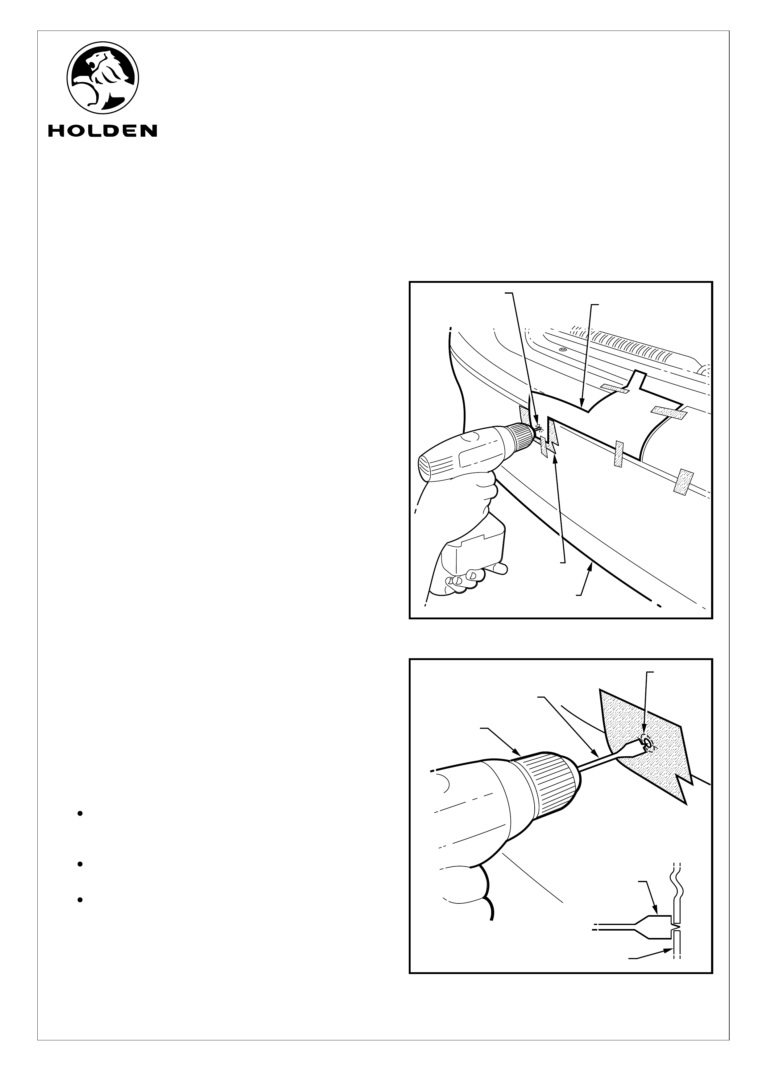
Place masking tape over the area of the bumper fascia
to be drilled. Refer to Figure 1.
2. Drill pilot holes through the templates and fascia (4
places) using a 2.0 mm drill bit. Refer to Figure 1.
3. Remove the templates and drill 22.2mm dia. holes
through the fascia (4 places), using the Lumen spade
drill bit. Refer to Figure 2.
IMPORTANT:
Use only the Lumen spade drill bit as a normal
drill bit or hole saw may damage the bumper
fascia.
Ensure the spade drill bit remains square with
the bumper fascia.
Use 1,500 - 2,000 RPM (slow speed) drill speed
only to avoid damaging the bumper fascia.
Ÿ
Ÿ
Ÿ
FIGURE 1
FITTING INSTRUCTIONS FOR
REVERSE PARKING SENSOR SYSTEM
FIGURE 2
PILOT HOLE
2.0mm DIA
(4 PLACES)
MASKING
TAPE
TEMPLATE
BUMPER
FASCIA
(4 PLACES)
LUMEN SPADE
DRILL BIT
ENSURE DRILL
BIT REMAINS
SQUARE WITH
BUMPER FASCIA
BUMPER FASCIA
1,500 - 2,000 RPM
DRILL SPEED
Page 2 of 18
HOLDEN LTD
Division of HOLDEN Ltd ACN 006 893 232
FD1105
03DE04
COPYRIGHT
Reproduction in whole or part
prohibited without written approval
FITTING INSTRUCTIONS FOR
REVERSE PARKING SENSOR SYSTEM
FITTING INSTRUCTIONS: - continued.
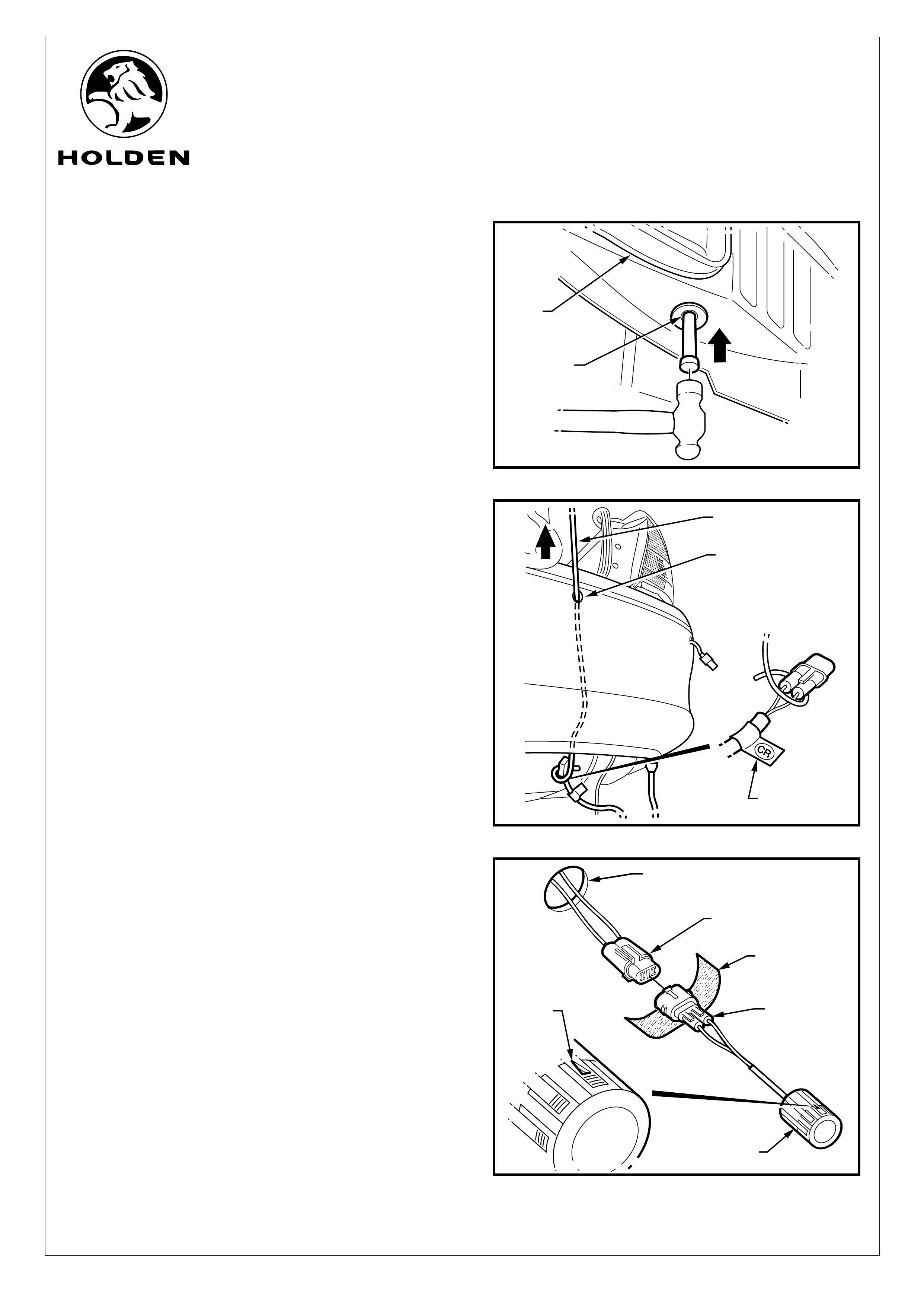
4. Remove the metal plug from behind the right-hand side
wheel arch below the air extraction vent, by knocking out
from beneath the vehicle. Refer to Figure 3.
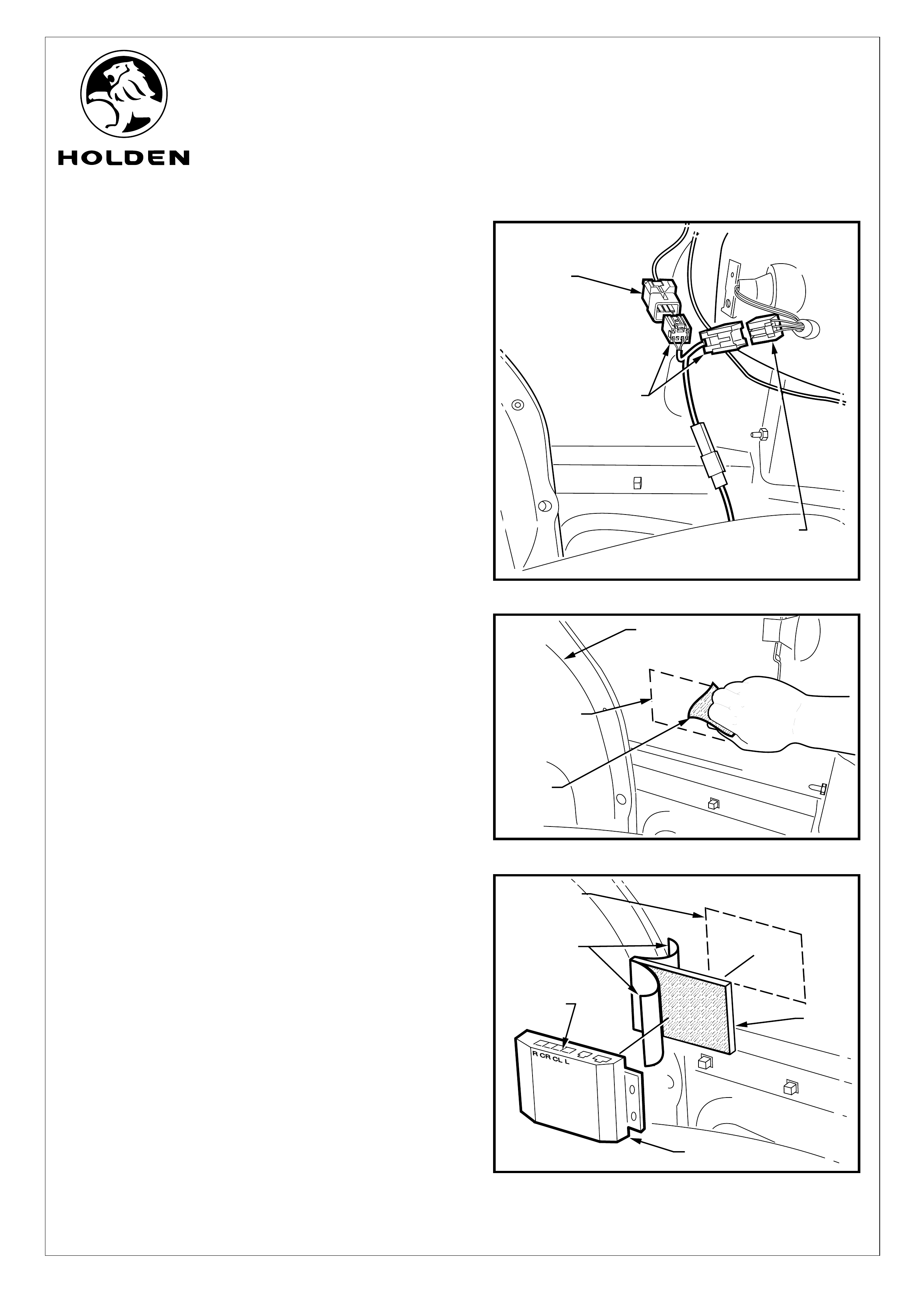
5. From inside the rear compartment, clean sufficient
sealant from around the metal plug hole to allow the new
harness grommet to seal securely.
6. Feed the reverse parking sensor (RPS) harness
connectors through the bumper fascia as follows:
Pass a piece of guide wire through the right-hand side
fascia hole, down between the bumper fascia and the
bumper reinforcement.
Fix the right hand side connector (R) to the wire and
pull back through the hole.
Use care when feeding the connector between the
fascia and bumper reinforcement.
Repeat for the centre-right (CR), the centre left (CL)
and the left (L) connectors.
NOTE: Ensure the harness connectors correspond to
the position of the sensors. This is indicated by a label
situated behind the harness connector as follows:
L- Left
CL - Centre Left
CR - Centre Right
R- Right
Refer to Figure 4.
7. Peel the protective backing off the foam strip and wrap
firmly around the sensor connectors. Refer to Figure 5.
8. Connect the sensors to the RPS harness connectors.
Refer to Figure 5.
9. Pass the connectors back through the holes then press
fit the reverse parking sensors (4 places) into the holes
drilled in the fascia.
IMPORTANT: Ensure the arrow on the sensor body
faces the top of the fascia. Refer to Figure 5.
FIGURE 3
FIGURE 4
FIGURE 5
PULL CONNECTOR
THROUGH HOLE
GUIDE
WIRE
CONNECTOR
IDENTIFICATION
SENSOR
SENSOR
CONNECTOR
FOAM STRIP
(WRAP AROUND
CONNECTOR)
HARNESS
CONNECTOR
RPS HARNESS
CONNECTOR
22mm DIA.
BUMPER FASCIA
HOLE
'TOP'
MARK
METAL
PLUG
AIR
EXTRACTION
VENT
Page 3 of 18
HOLDEN LTD
Division of HOLDEN Ltd ACN 006 893 232
FD1105
03DE04
COPYRIGHT
Reproduction in whole or part
prohibited without written approval
FITTING INSTRUCTIONS FOR
REVERSE PARKING SENSOR SYSTEM
FITTING INSTRUCTIONS: - continued.
Refer to Figure 6 for the following:
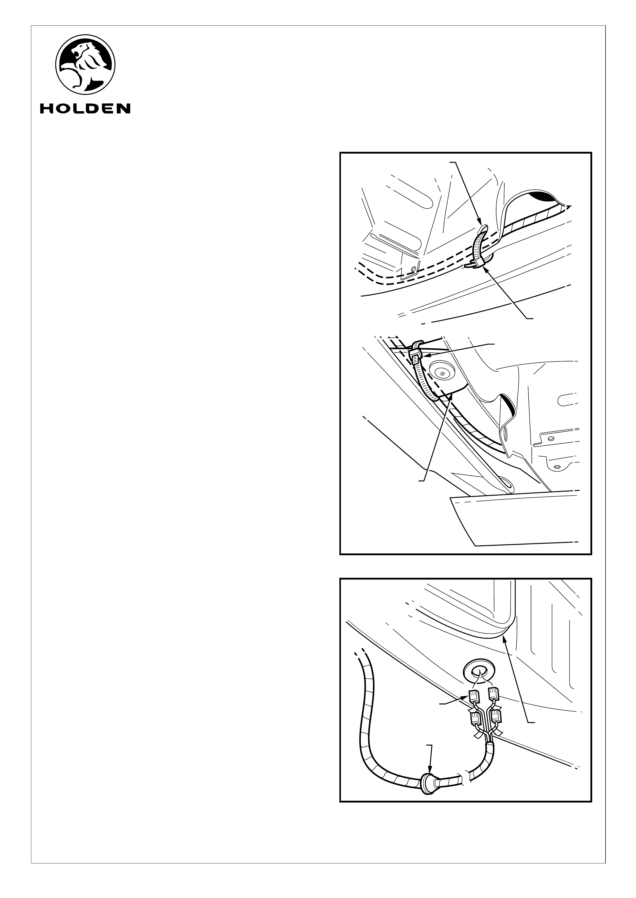
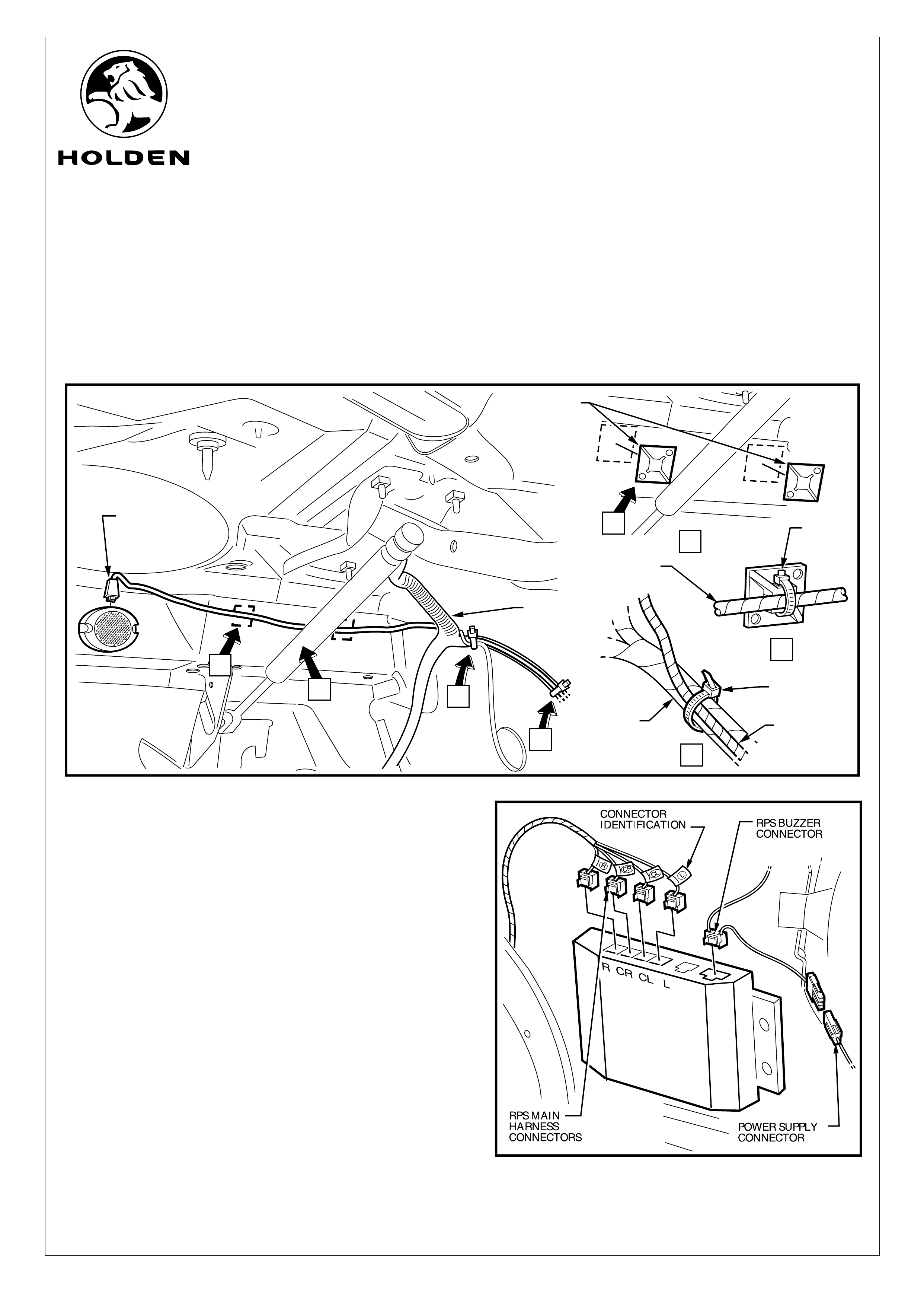
10. Tie strap the RPS harness (2 places) as follows:
a. Tie strap securely to the hole on the right-hand side
of the lower rear panel.
b. Tie strap loosely to the left-hand side bumper fascia
support bracket.
11. Feed the RPS harness module connectors through the
hole behind the right-hand side rear wheel arch below
the air extraction vent, and fit the grommet securely in
position. Refer to Figure 7.
NOTE: Ensure the grommet mounting hole surround is
clean and free from sealant to allow the grommet to seal
securely.
AIR
EXTRACTION
VENT
FIGURE 6
FIGURE 7
CABLE TIE
BUMPER FASCIA
SUPPORT BRACKET
(LEFT-HAND SIDE
CABLE TIE
LOWER REAR HOLE
(RIGHT-HAND SIDE)
GROMMET
RPS HARNESS
MODULE
CONNECTORS
Page 4 of 18
HOLDEN LTD
Division of HOLDEN Ltd ACN 006 893 232
FD1105
03DE04
COPYRIGHT
Reproduction in whole or part
prohibited without written approval
FITTING INSTRUCTIONS FOR
REVERSE PARKING SENSOR SYSTEM
FITTING INSTRUCTIONS: - continued.
12. Unclip the rear compartment liner from the right-hand
side rear quarter panel and parcel shelf area.
Disconnect the existing right-hand side rear
compartment tail light connector. Refer to Figure 8.
13. Fit the corresponding connectors on the RPS main
wiring harness between the connectors on the right-
hand side rear compartment tail light harness.
Refer to Figure 8.
14. The RPS module mounts on the inside of the right-hand
side rear quarter panel behind the wheel arch as
indicated.
NOTE: Before fitting the module, clean the mounting
area then wipe with the hi-tech cleaning pad supplied
(retain pad for later use). Also wipe the back of the RPS
module. Refer to Figure 9.
15. Peel the backing off one side of the RPS module velcro
mounting pad and press fit firmly to the back of the RPS
module. Refer to Figure 10.
16. Peel the backing off the remaining side of the velcro
mounting pad and press fit the RPS module onto the
inner rear quarter panel in the position indicated,
ensuring the WIRING CONNECTOR SOCKETS FACE
"UP". Apply pressure to the RPS module unit to ensure
a secure fit. Refer to Figure 10.
FIGURE 8
EXISTING
RIGHT-HAND
SIDE TAIL LAMP
CONNECTOR
RPS MAIN
WIRING HARNESS
CONNECTORS
EXISTING
RIGHT-HAND
SIDE TAIL LAMP
CONNECTOR
FIGURE 9
RPS MODULE
MOUNTING
LOCATION
HI-TECH
CLEANING
PAD
RIGHT-HAND SIDE
REAR WHEEL ARCH
PROTECTIVE
BACKING
RPS MODULE
MOUNTING
LOCATION
RPS MODULE
VELCRO
PAD
FIGURE 10
WIRING
SOCKETS
Page 5 of 18
HOLDEN LTD
Division of HOLDEN Ltd ACN 006 893 232
FD1105
03DE04
COPYRIGHT
Reproduction in whole or part
prohibited without written approval
SWITCH SET
TO 'Hi' POSITION
FIGURE 11
FIGURE 12
FITTING INSTRUCTIONS FOR
REVERSE PARKING SENSOR SYSTEM
FITTING INSTRUCTIONS: - continued.
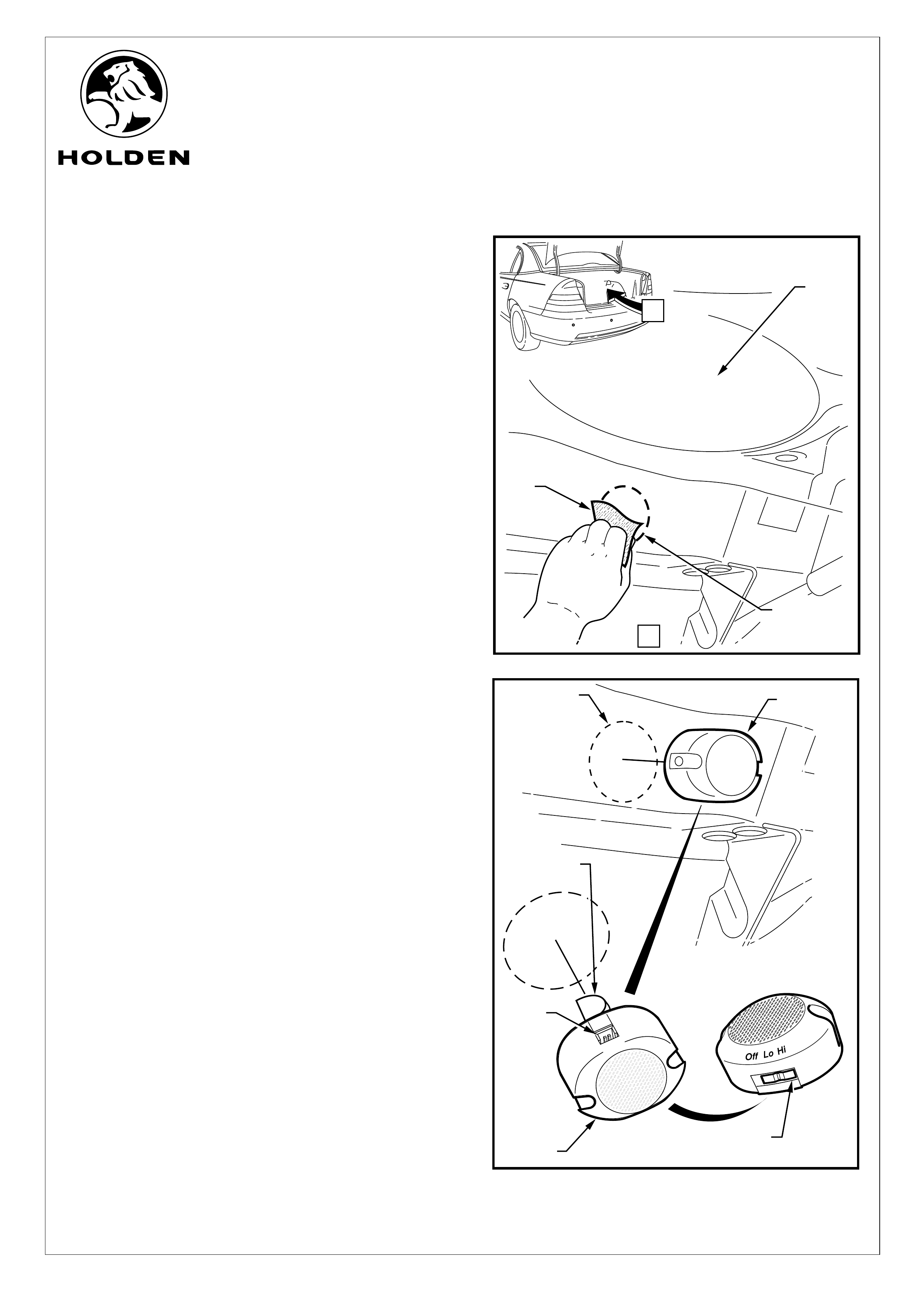
17. The RPS buzzer mounts in the rear compartment under
the rear parcel shelf as indicated. Clean the mounting
area then wipe with the hi-tech cleaning pad supplied
(retain pad for later use). Refer to Figure 11.
Refer to Figure 12 for the following:
18. Peel the protective backing off the RPS buzzer and
press fit in the position indicated ensuring the WIRING
SOCKET FACES "UP". Apply pressure to the buzzer
unit to ensure a secure fit.
NOTE: Prior to fitting the buzzer, ensure the switch is set
to 'Hi'. Refer to Figure 12.
REAR
PARCEL
SHELF
RPS BUZZER
MOUNTING
LOCATION
HI-TECH
CLEANING
PAD
RPS BUZZER
RPS BUZZER
MOUNTING
LOCATION
RPS
BUZZER
WIRING
SOCKET
PROTECTIVE
BACKING
A
Page 6 of 18
VIEW A
HOLDEN LTD
Division of HOLDEN Ltd ACN 006 893 232
FD1105
03DE04
COPYRIGHT
Reproduction in whole or part
prohibited without written approval
CABLE TIE
SECURING
PADS
FIGURE 13
FITTING INSTRUCTIONS FOR
REVERSE PARKING SENSOR SYSTEM
21. Connect the RPS buzzer harness connector to the
RPS module. Refer to Figure 14.
22. Connect the four RPS harness connectors into the RPS
module. Ensure the harness connectors correspond to
the positions in the module. This is indicated by a label
situated behind the connectors and on the front face of
the RPS module as follows:
L- Left
CL - Centre Left
CR - Centre Right
R- Right
Refer to Figure 14.
23. Connect the RPS power supply harness connector to
the corresponding RPS main wiring harness connector.
Refer to Figure 14.
FITTING INSTRUCTIONS: - continued.
19. Connect the RPS buzzer harness connector to the buzzer and route to the right-hand side of the parcel shelf and
follow the existing vehicle harness to the RPS module. Tie strap the RPS buzzer harness to the existing vehicle
harness in two places. Refer to Figure 13 (View C).
20. Clean the underside of the rear parcel shelf in the positions indicated (2 places) and wipe with the high-tech cleaning
pad supplied. Press fit the two cable tie securing pads in the positions indicated (View A). Secure the RPS buzzer
harness to the parcel shelf at these two locations with cable ties. Refer to Figure 13 (View B).
A
B
C
A
B
C
RPS BUZZER
HARNESS
CONNECTOR
C
RPS BUZZER
HARNESS
EXISTING
VEHICLE
HARNESS
CABLE TIE
CABLE
TIE
RPS BUZZER
HARNESS
EXISTING
VEHICLE
HARNESS
B
FIGURE 14
Page 7 of 18
HOLDEN LTD
Division of HOLDEN Ltd ACN 006 893 232
FD1105
03DE04
COPYRIGHT
Reproduction in whole or part
prohibited without written approval
FITTING INSTRUCTIONS FOR
REVERSE PARKING SENSOR SYSTEM
VT, VX, VY & WL REVERSE PARKING SENSOR SYSTEM
PARTS LIST
FITTING INSTRUCTIONS: - continued.
24. Neatly cable tie excess wiring harness.
25. Fix the caution label in a prominent position (above tyre
placard on drivers side door).
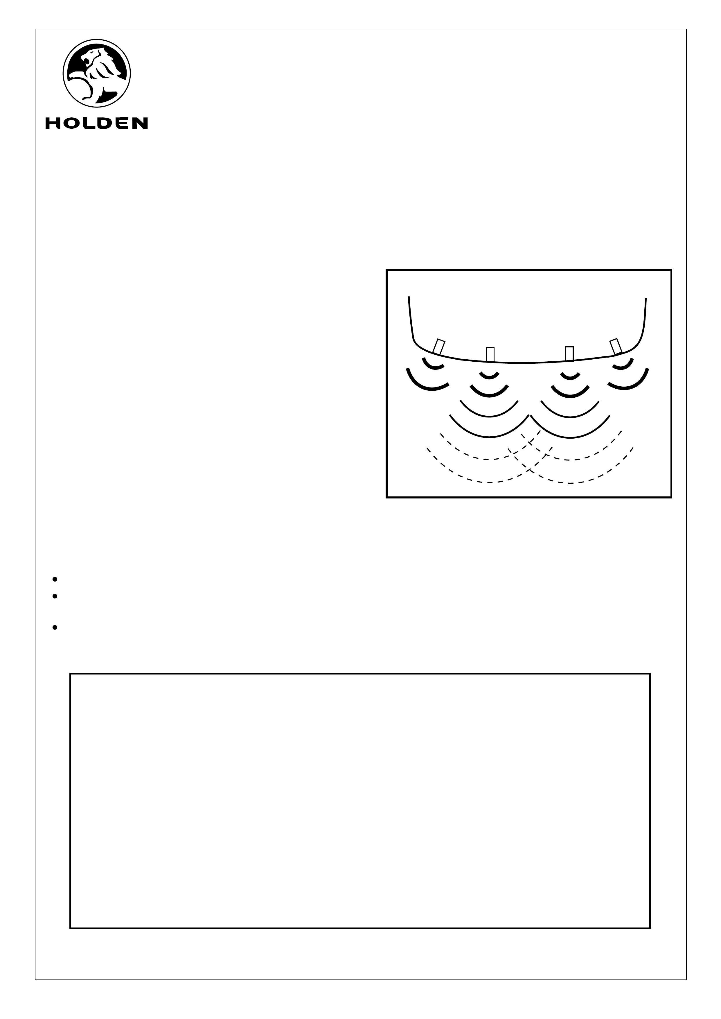
26. Test the reverse parking sensor system for correct
operation as follows:
Turn the ignition to the "ON" position (engine not
running).
Place the gear lever in reverse (R).
From behind the vehicle, walk towards each sensor.
The two centre sensors have 3 stages.
The two corner sensors only have 1 stage of final
warning. Refer to Figure 15.
Refer to the owners manual for further information
and trouble shooting.
Turn the ignition to the "OFF" position.
27. Refit all removed parts and torque fasteners to
specifications.
28. Place fitting instructions in the glovebox.
IMPORTANT:
DO NOT paint over the reverse parking sensor.
Ensure the reverse parking sensor remains clean
and free from road grime, mud, car polish etc.
If the sensor or the groove on the sensor surface
becomes contaminated, the performance may be
affected.
Ÿ
Ÿ
Ÿ
PART NUMBER DESCRIPTION QUANTITY
92144863 REVERSE PARKING SENSOR SYSTEM
REVERSE PARKING SENSOR MAIN HARNESS 1
REVERSE PARKING SENSOR HARNESS 1
REVERSE PARKING SENSOR BUZZER HARNESS 1
REVERSE PARKING SENSOR 4
REVERSE PARKING BUZZER 1
REVERSE PARKING SENSOR MODULE VELCRO MOUNTING PAD 1
REVERSE PARKING SENSOR FOAM SEAL 4
REVERSE PARKING SENSOR BUZZER HARNESS ADHESIVE PADS 2
CABLE TIE 10
HI-TECH CLEANING PAD 1
INSTRUCTION MANUAL 1
FD 1105 FITTING INSTRUCTIONS 1
FIGURE 15
Page 8 of 18