11.0~3.0 Nm
REMOVE
RETAINERS
(4 PLACES)
1
REMOVE
ATTACHING
SCREWS
(5 PLACES)
FRONT OF
VEHICLE
FIGURE 1
COPYRIGHT
Page 1 of 15
HOLDEN LTD
Reproduction in whole or part
prohibited without written approval
Division of HOLDEN Ltd ACN 006 893 232
FITTING INSTRUCTIONS FOR
CREW CAB REVERSE PARKING AID SENSOR PACKAGE
Part No. 92148000
FD1166
18JULY03
FITTING INSTRUCTIONS:
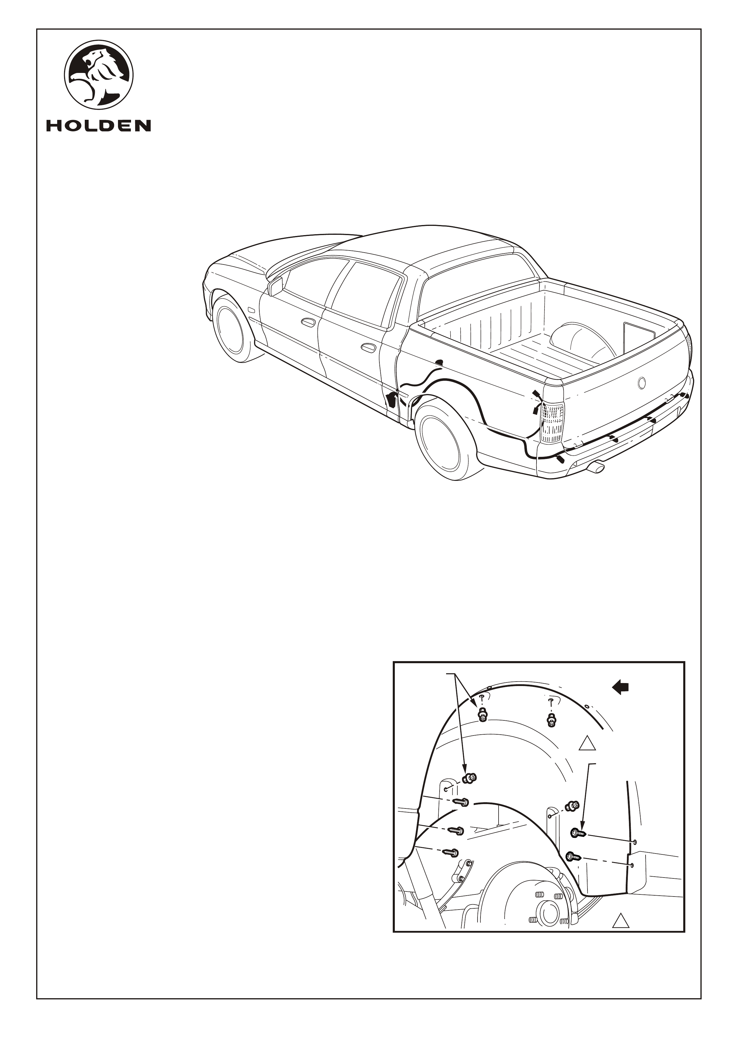
1. If fitted, remove any wheel trim covering the wheel nuts
from the rear left-hand wheel and place to one side.
Loosen wheel nuts, raise vehicle and remove nuts and
wheel. Refer to vehicles owners handbook for further
information.
2. Remove the five rear left-hand side wheelhouse liner
attaching screws and the four retainers attaching the
liner to the wheelhouse panel, refer to Figure 1.
3. Manipulate the liner from behind the wheelhouse panel
and remove.
TOOLS REQUIRED:
Wheel Wrench, Philips Head Screwdriver, Flat Blade
Screwdriver, Socket Wrench and 13 mm Socket, Hoist
(Recommended), 2.0 mm Drill Bit, 22.0 mm Wood Spade
Drill Bit, Cleaning Cloth, Hi-tech Cleaning Pad (Supplied),
Guide Wire (approx. 600 mm).
COPYRIGHT
Page 2 of 15
HOLDEN LTD
Reproduction in whole or part
prohibited without written approval
Division of HOLDEN Ltd ACN 006 893 232
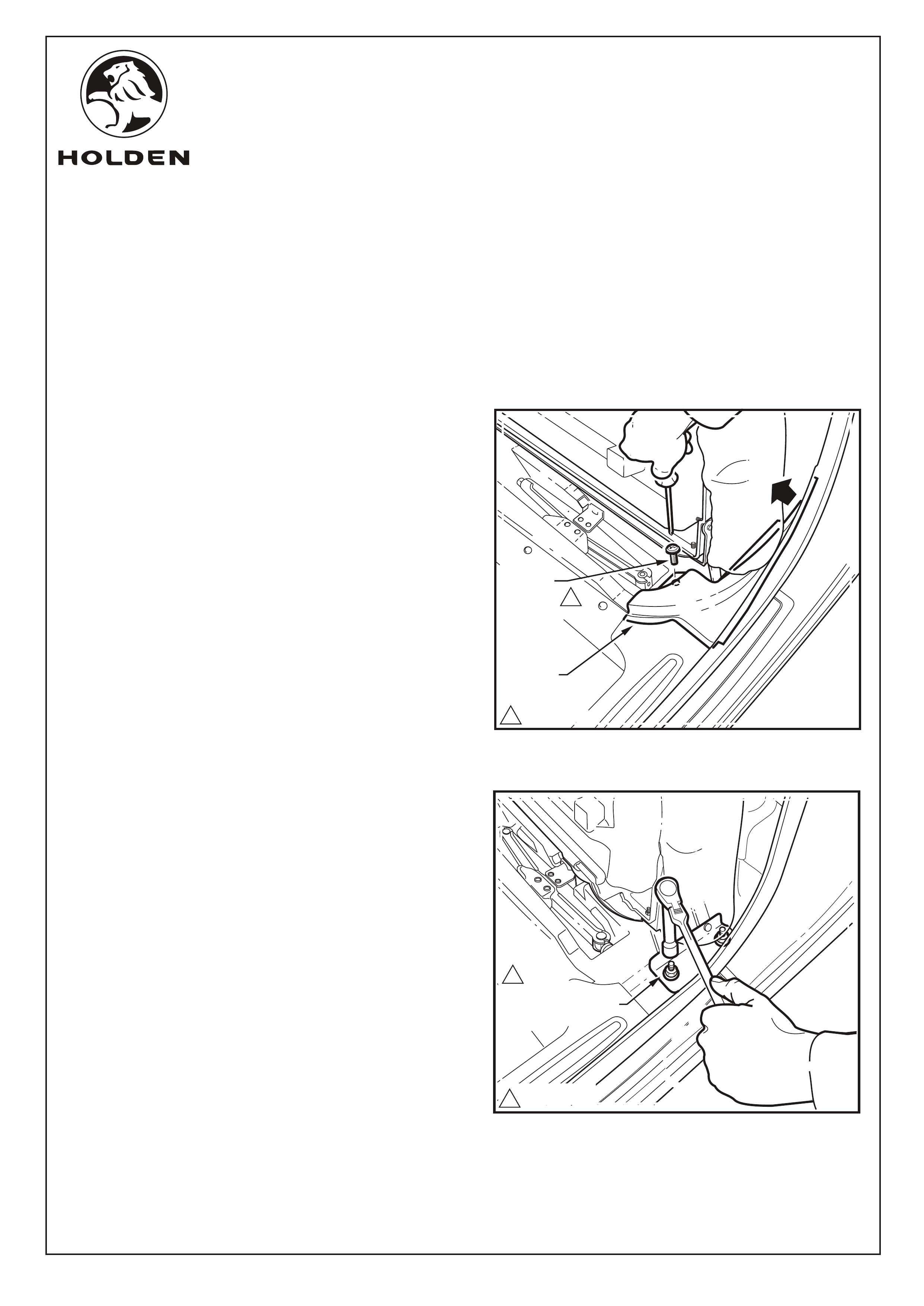
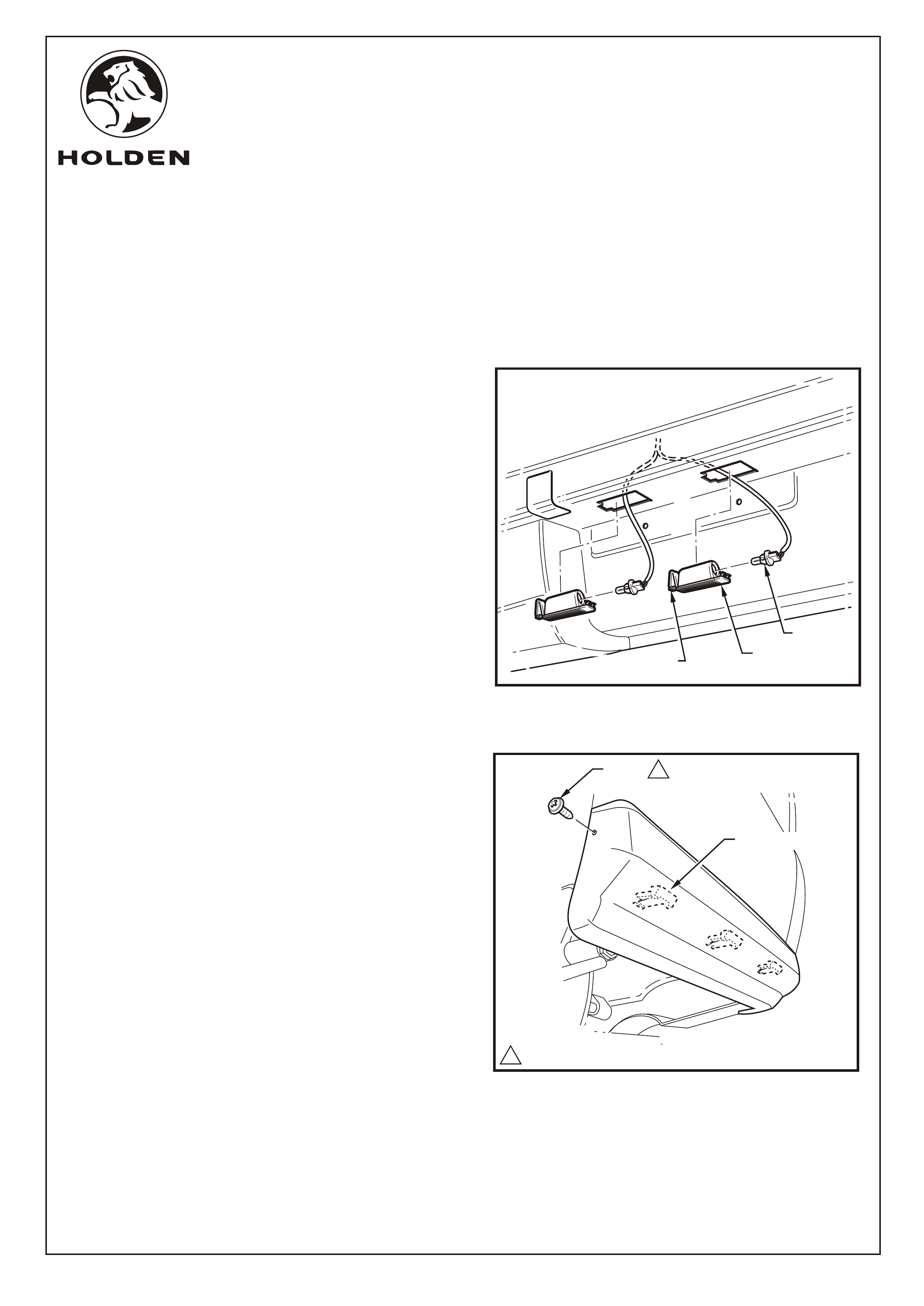
Refer to Figure 2 for the following:
4. Press the rear seat base release handle and fold and
hold the seat base in the upright position.
5. Remove attaching screw from the left-hand side interior
rocker panel extension moulding. Grasp the moulding
and pull to remove it from behind the seat cushioning
and door sill. Repeat on opposite side of vehicle.
6. Remove the two left-hand side seat bracket to floor
panel attaching nuts. Repeat on opposite side of vehicle.
Refer to Figure 3.
7. Lift the seat base up and off the floor studs and remove
from vehicle.
FITTING INSTRUCTIONS: - continued
FIGURE 2
REMOVE
FINISHER
REMOVE
ATTACHING
SCREW
REMOVE SEAT
BRACKET ATTACHING
NUT (4 PLACES)
FIGURE 3
FITTING INSTRUCTIONS FOR
CREW CAB REVERSE PARKING AID SENSOR PACKAGE
11.0~3.0 Nm
1
1
125 ~ 35 Nm
FD1166
18JULY03
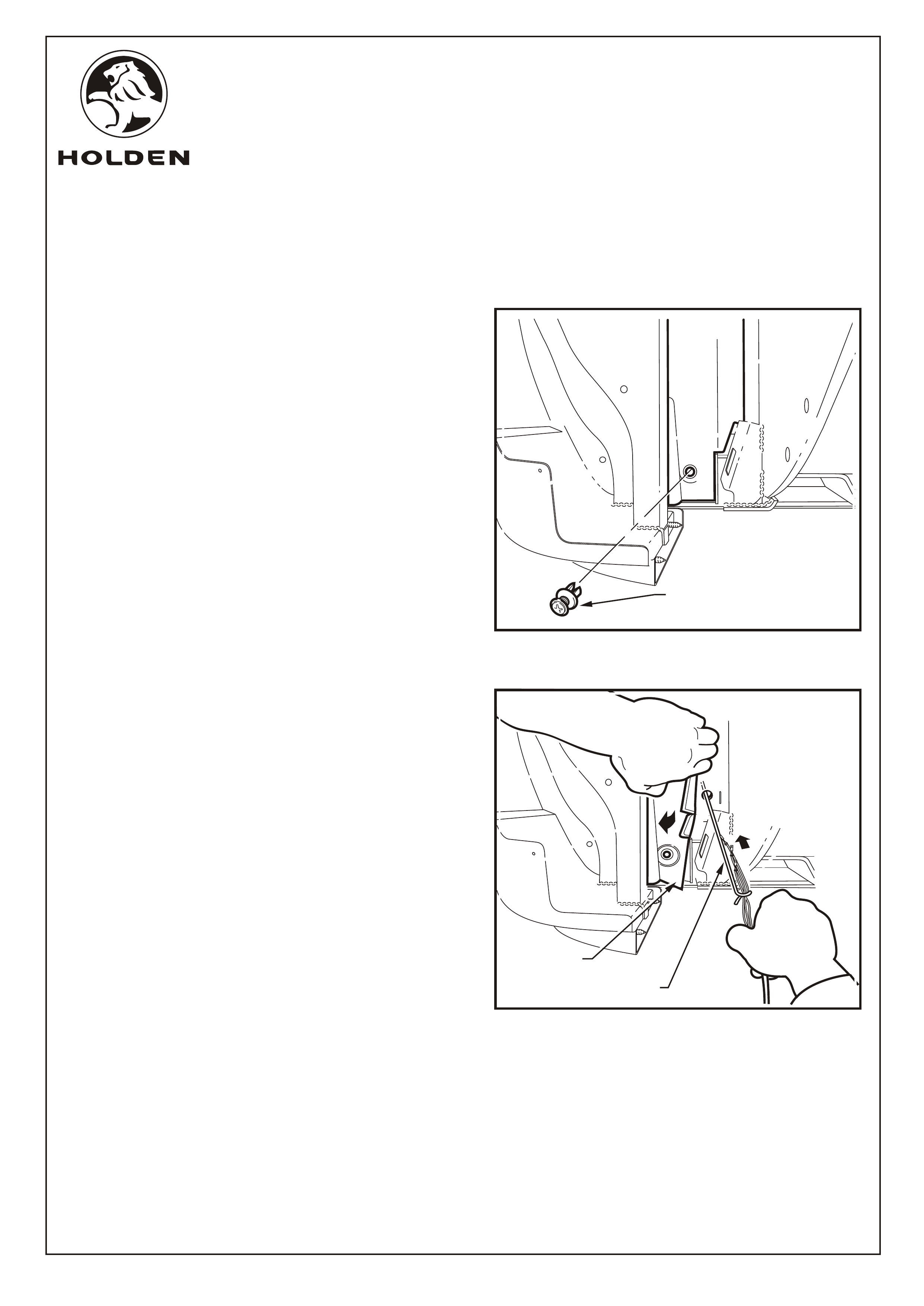
FIGURE 4
COPYRIGHT
Page 3 of 15
HOLDEN LTD
Reproduction in whole or part
prohibited without written approval
Division of HOLDEN Ltd ACN 006 893 232
8. Remove the outer panel scrivet from the lower left-hand
side outside quarter of the cabin. Refer to Figure 4.
Refer to Figure 5 for the following:
9. Fold back the outer panel and reposition foam insulation
to allow access to the existing 12mm cabin hole.
10. Feed a guide wire through the hole.
11. Attach the main RPS harness to the guide wire with the
terminals staggered and pull harness through hole until
the RPS harness grommet meets with the hole. If
required, wrap electrical tape around guide wire and
terminals to aid installation.
12. Secure grommet into place.
NOTE: Ensure the hole surround is clean and free from
sealant or adhesive to allow the grommet to seal
correctly.
FITTING INSTRUCTIONS: - continued
FIGURE 5
REMOVE SCRIVET
GUIDE WIRE
PULL BACK
OUTER PANEL
FITTING INSTRUCTIONS FOR
CREW CAB REVERSE PARKING AID SENSOR PACKAGE
FD1166
18JULY03
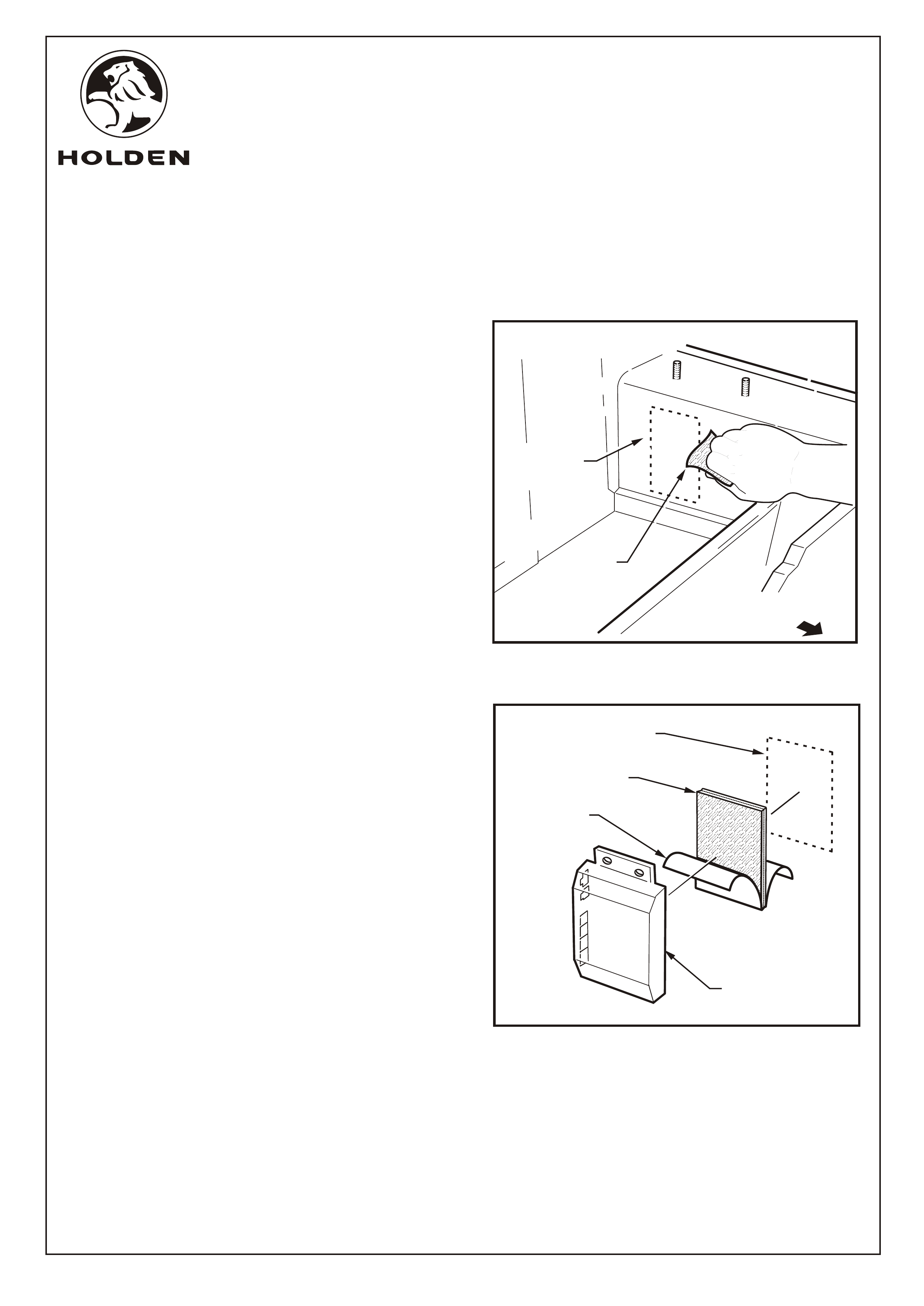
FIGURE 6
13. From inside the cabin, along the left-hand side inner sill
clean the RPS module mounting location using high-
tech cleaning pad supplied. Refer to Figure 6.
14. Wipe the back face of the RPS module using high-tech
cleaning pad.
Refer to Figure 7 for the following:
15. Peel one side of protective backing from RPS module
velcro and press fit velcro pad firmly to the back face of
the RPS module.
16. Peel backing off remaining side of the velcro pad. Press
fit the RPS module onto left hand side inner sill.
17. Apply pressure to the RPS module to ensure a secure fit
and full adhesion.
COPYRIGHT
Page 4 of 15
HOLDEN LTD
Reproduction in whole or part
prohibited without written approval
Division of HOLDEN Ltd ACN 006 893 232
FIGURE 7
RPS MODULE
MOUNTING
LOCATION
FITTING INSTRUCTIONS: - continued
HI-TECH
CLEANING
PAD
PROTECTIVE
BACKING
RPS MODULE
MOUNTING
LOCATION
VELCRO
PAD
RPS
MODULE
FITTING INSTRUCTIONS FOR
CREW CAB REVERSE PARKING AID SENSOR PACKAGE
FD1166
18JULY03
FRONT OF
VEHICLE
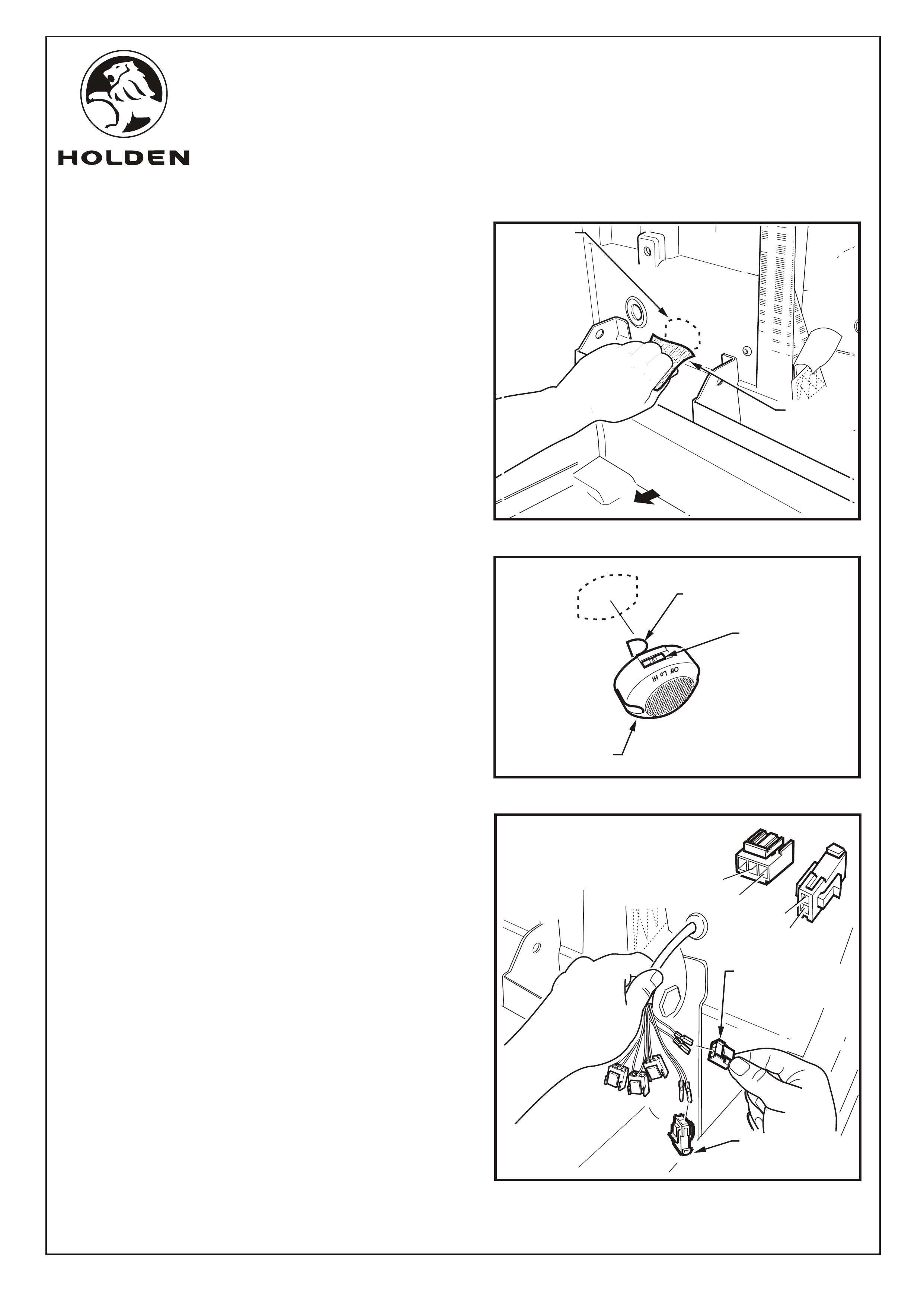
FIGURE 10
2
3
1
1
2
COPYRIGHT
Page 5 of 15
HOLDEN LTD
Reproduction in whole or part
prohibited without written approval
Division of HOLDEN Ltd ACN 006 893 232
FIGURE 8
18. Clean the RPS buzzer mounting location using high-
tech cleaning pad, at the location indicated, along the
lower left-hand side of the rear cabin paneling. Refer to
Figure 8.
Refer to Figure 9 for the following:
19. Attach RPS buzzer velcro pad supplied onto the existing
RPS buzzer velcro patch.
20. Peel backing from velcro pad and press fit the buzzer
onto the cabin panel as indicated, with the switch facing
up.
21. Apply pressure to the RPS buzzer unit to ensure a
secure fit and full adhesion.
Refer to Figure 10 for the following:
22. Connect tagged RPS main harness wire terminals to the
3-way female connectors supplied, according to table
below:
PIN 1 PIN 2 PIN 3
Left N/A BK/BL RD/WH
Centre Left N/A BN BL
Centre Right N/A GN WH
Right N/A GY YL
FITTING INSTRUCTIONS: - continued
RPS BUZZER
MOUNTING
LOCATION
HI-TECH
CLEANING
PAD
SET SWITCH
TO 'Hi' POSITION
RPS
BUZZER
PROTECTIVE
BACKING
FIGURE 9
FD1166
18JULY03
FRONT OF
VEHICLE
FEMALE 3-WAY
MAIN HARNESS TO
MODULE CONNECTOR
(4 PLACES)
23. Connect two remaining male terminal wires into the two
way female connector supplied, according to table
below:
PIN 1 PIN 2
Buzzer/Power BK RD
FEMALE 2-WAY
POWER SUPPLY
CONNECTOR
FITTING INSTRUCTIONS FOR
CREW CAB REVERSE PARKING AID SENSOR PACKAGE
P2
P3
P1
P2
TAPE BUNDLED
HARNESS TO
CABIN PANEL
FEED HARNESS FROM
MODULE TO BUZZER
AND CONNECT
CONNECTOR
IDENTIFICATION
POWER
SUPPLY
CONNECTOR
2-WAY
MAIN HARNESS TO
MODULE CONNECTORS
3-WAY
RPS BUZZER
CONNECTOR
4-WAY
L
CL
CR
R
COPYRIGHT
Page 6 of 15
HOLDEN LTD
Reproduction in whole or part
prohibited without written approval
Division of HOLDEN Ltd ACN 006 893 232
FIGURE 12
FIGURE 11
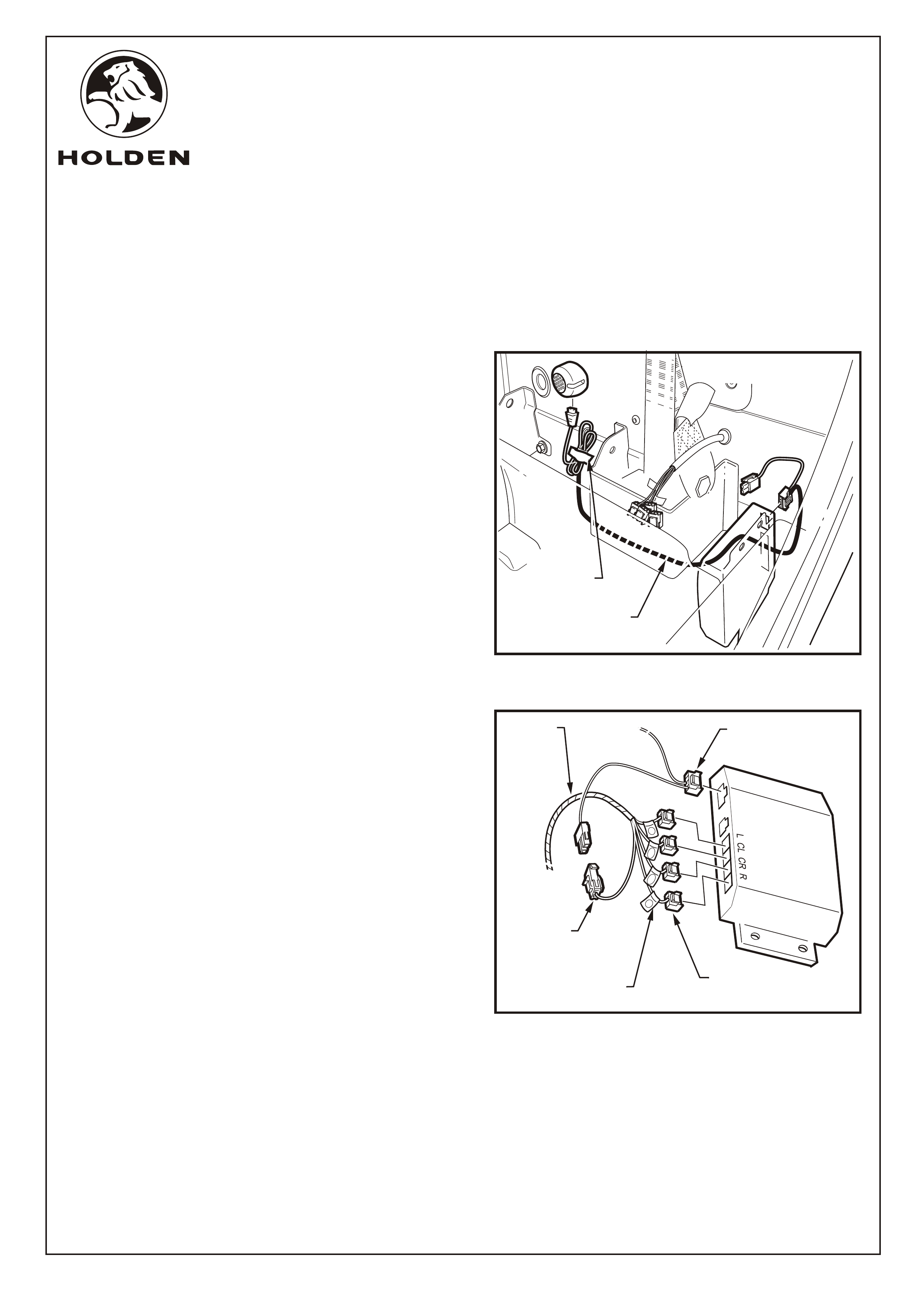
FITTING INSTRUCTIONS: - continued
Refer to Figure 11 for the following:
24. Feed the buzzer harness from the RPS module to the
RPS buzzer by running the harness underneath the
seatbelt retractor bracket. Connect the buzzer
connector to the buzzer.
Refer to Figure 12 for the following:
25. Connect all four of the 3-way main RPS harness to
module connectors into the RPS module.
26. Connect the 4-way RPS buzzer connector into the RPS
module.
27. Connect the 2-way main RPS harness power supply
female connector to the flying 2-way RPS buzzer
harness connector.
NOTE: Ensure each tagged wire and connector is
installed against its corresponding connector as marked
on the RPS module.
28. Bundle and tape excess RPS buzzer harness and
secure to the cabin paneling using suitable tape. Refer
to Figure 11.
FITTING INSTRUCTIONS FOR
CREW CAB REVERSE PARKING AID SENSOR PACKAGE
FD1166
18JULY03
MAIN RPS
HARNESS
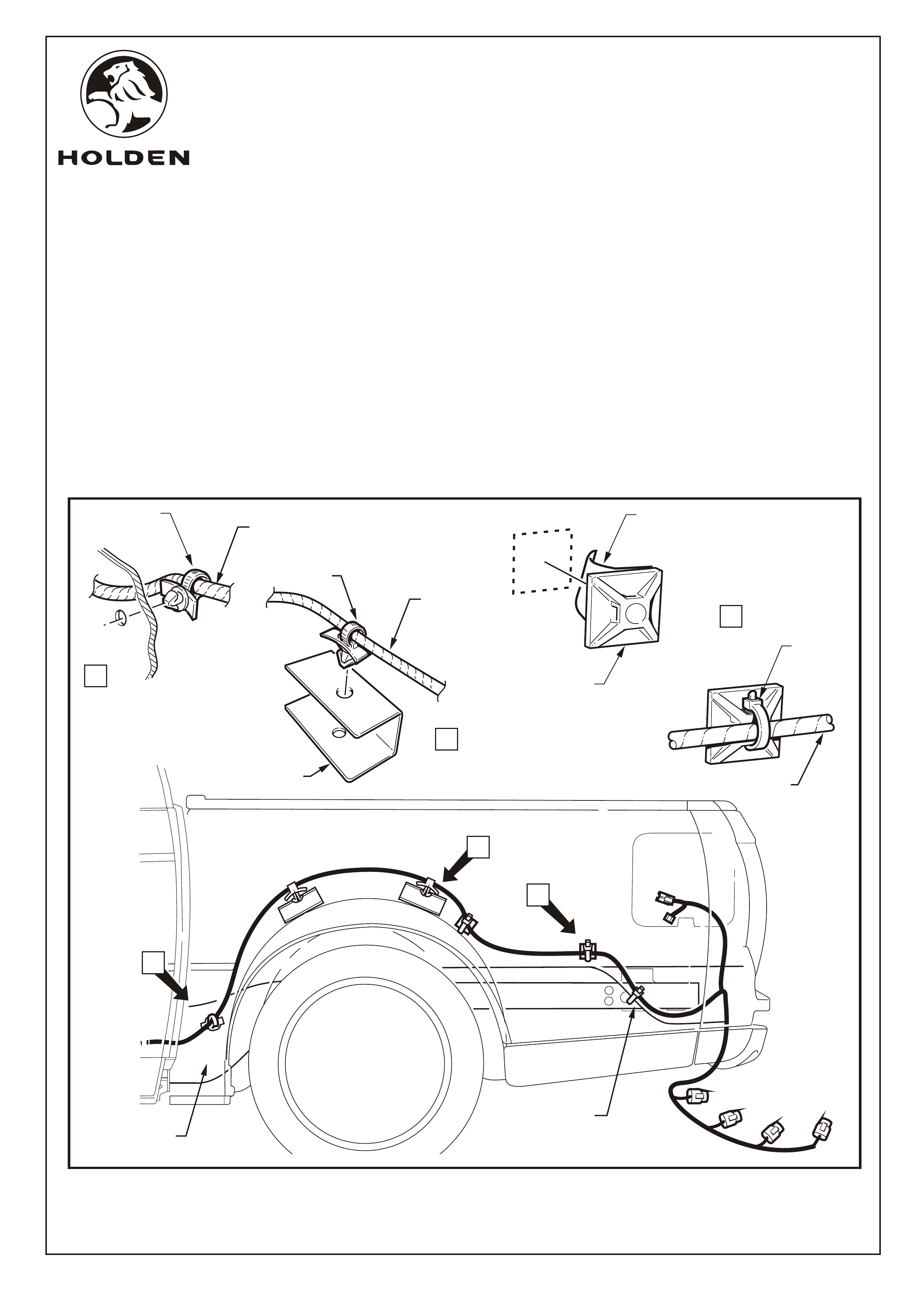
FITTING INSTRUCTIONS: - continued
Refer to Figure 13 for the following:
29. On the left-hand underside of the vehicle, clean the vehicle surface at all securing points indicated below. Wipe
cable tie securing pad mounting surfaces with high-tech cleaning pad supplied.
30. Route harness as shown below and clip the harness by the cable tie clips to the rear body chassis rail, View A, and
the wheel arch bracket, View B.
31. Remove protective backing from cable tie attaching pads and press fit at two locations shown, refer to View C.
32. Loosely tie strap the harness to each of the securing pads as indicated, refer to View C.
33. Loosely tie strap the harness to the lower skirting of the tub paneling using the existing hole in the panel.
COPYRIGHT
Page 7 of 15
HOLDEN LTD
Reproduction in whole or part
prohibited without written approval
Division of HOLDEN Ltd ACN 006 893 232
FITTING INSTRUCTIONS FOR
CREW CAB REVERSE PARKING AID SENSOR PACKAGE
FD1166
18JULY03
B
B
ATTACH
SECURING
PAD (2 PLACES)
REMOVE
PROTECTIVE
BACKING
A
REAR BODY
CHASSIS RAIL
TIE STRAP HARNESS
TUB PANELING LOWER
SKIRTING
CABLE
TIE
MAIN RPS
HARNESS
A
MAIN RPS
HARNESS
C
CABLE
CLIP
C
MAIN RPS
HARNESS
WHEEL ARCH
BRACKET
(2 PLACES)
CABLE
CLIP
FIGURE 13
SCREW
(8 PLACES)
COVER PANEL
1
11.0 ~ 3.0 Nm
PULL PATCH OF
RPS HARNESS
THROUGH CAVITY
COPYRIGHT
Page 8 of 15
HOLDEN LTD
Reproduction in whole or part
prohibited without written approval
Division of HOLDEN Ltd ACN 006 893 232
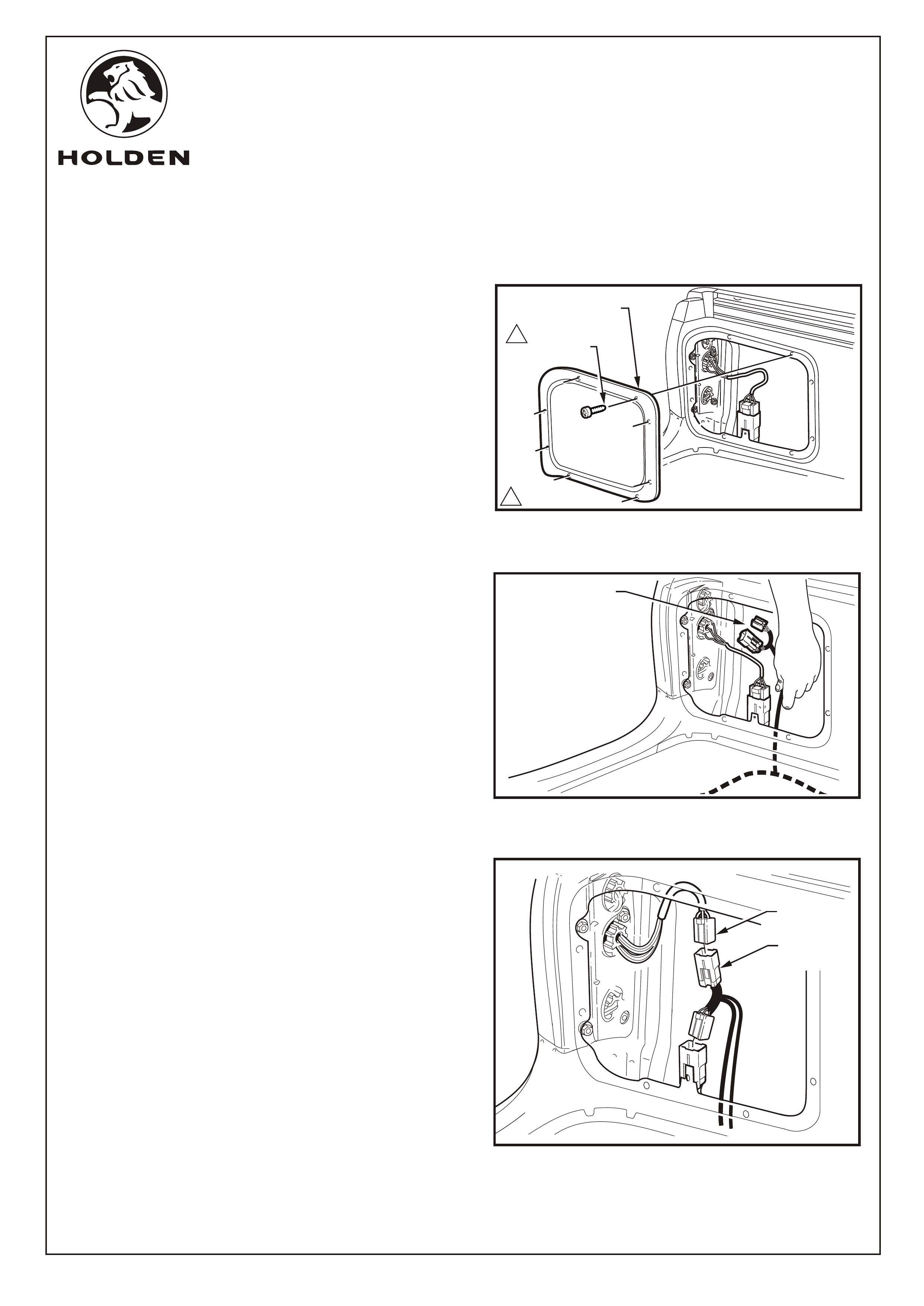
FITTING INSTRUCTIONS: - continued
34. Remove the rear inner LHS cover panel by removing
the eight attaching screws and prising the cover away
from the side panel. Refer to Figure 14.
35. Remove water proof foam from cavity and pull the RPS
patch harness branch of the main RPS harness up to
the tail lamp assembly. Refer to Figure 15.
Refer to Figure 16 for the following:
36. Disconnect the tail lamp connector from the main
harness.
37. Connect the RPS patch harness to the tail lamp and
main harness connectors.
COPYRIGHT
TAILL LAMP
CONNECTOR
PPS PATCH
CONNECTOR
FIGURE 14
FIGURE 15
FIGURE 16
FD1166
18JULY03
FITTING INSTRUCTIONS FOR
CREW CAB REVERSE PARKING AID SENSOR PACKAGE
FITTING INSTRUCTIONS: - continued
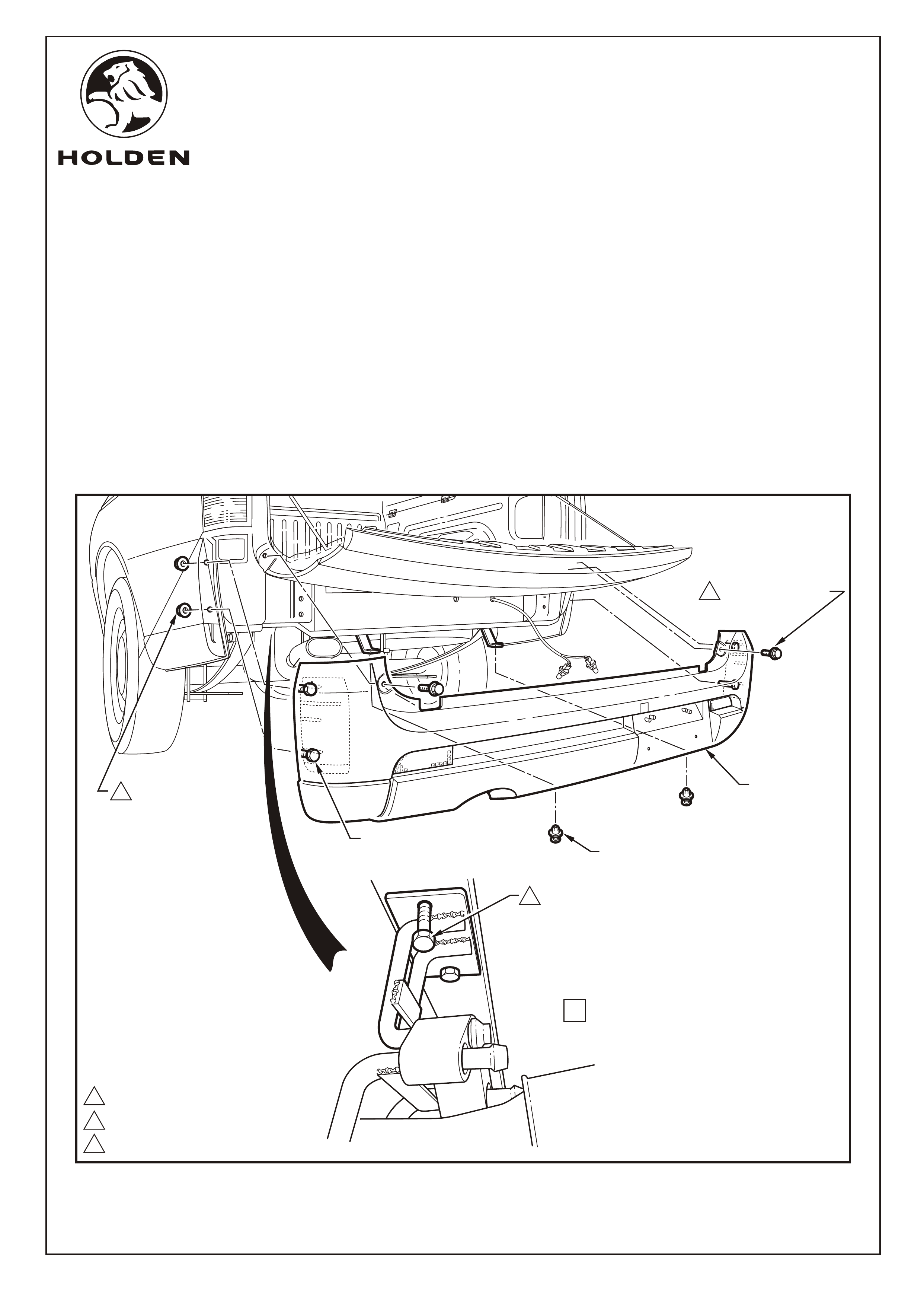
NOTE: Removal of the rear bumper fascia is necessary to
perform the rear bumper sensor hole drilling operations.
Refer to Figure 17 for the following:
38. Push the locking tang located at the end of the lamp
housing towards the lens. Pivot the lamp housing down
and remove it from the aperture.
39. Remove the bulb socket from the lamp housing and
place the lamp housing in a safe location.
40. Pass the bulb socket through the aperture in the rear
bumper fascia assembly.
41. Repeat Steps 38 to 40 for the other lamp assembly.
Refer to Figure 18 for the following:
42. For SS vehicles only:
a. Remove the rear body rear rocker moulding
attaching screw.
b. From behind the rear body panel unclip the retainer
clips in three places.
c. Repeat for the opposite side of the vehicle.
11.0 - 3.0 Nm
HOLDEN LTD
Division of HOLDEN Ltd ACN 006 893 232
Page 9 of 15
Reproduction in whole or part
prohibited without written approval
COPYRIGHT
FIGURE 17
FIGURE 18
FD1166
18JULY03
PRESS
LOCKING TANG
LAMP
HOUSING
BULB
SOCKET
RETAINER
CLIPS
SCREW 1
FITTING INSTRUCTIONS FOR
CREW CAB REVERSE PARKING AID SENSOR PACKAGE
118.0 - 25.0 N.m
26.0 - 9.0 N.m
SCRIVET (2 PLACES)
1
2
VIEW A
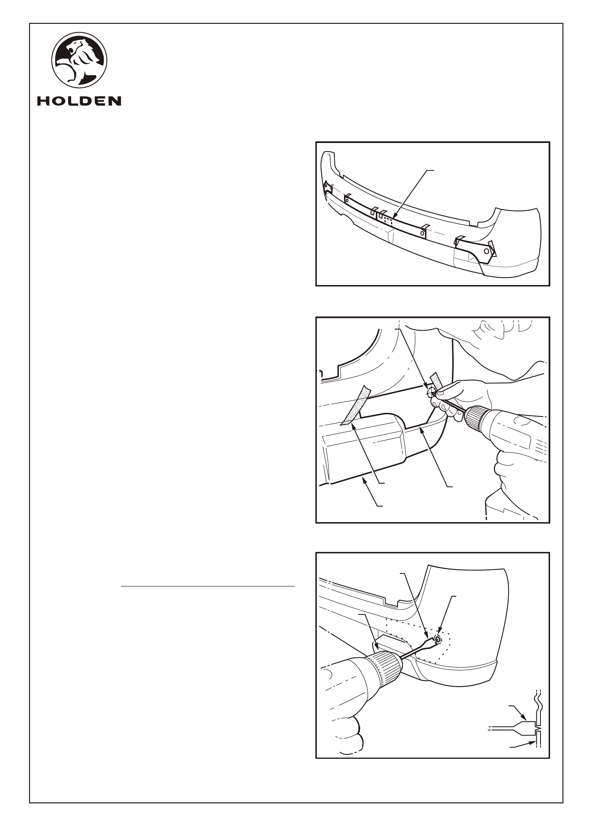
FITTING INSTRUCTIONS: - continued
Refer to Figure 19 for the following:
43. Remove the two scrivets from beneath the lower edge of the rear bumper fascia assembly.
44. Open the endgate, remove the two screws and close the endgate.
45. Remove the nuts from the studs, two places, from inside the rear side panel, on both sides.
46. Disengage the rear bumper fascia assembly from the fascia assembly supports. To assist rear bumper fascia
removal, loosen off the exhaust assembly support bracket attaching bolts, two places, to lower the exhaust tip
clear of the bumper fascia, refer to View A.
47. With the aid of an assistant, remove the rear bumper fascia assembly from the vehicle.
345 - 50 N.m
3
HOLDEN LTD
Division of HOLDEN Ltd ACN 006 893 232
Page 10 of 15
Reproduction in whole or part
prohibited without written approval
COPYRIGHT
FIGURE 19
FD1166
18JULY03
REAR BUMPER
FASCIA
STUD (4 PLACES)
NUT (4 PLACES)
BOLT (2 PLACES)
SCREW (2 PLACES)
FITTING INSTRUCTIONS FOR
CREW CAB REVERSE PARKING AID SENSOR PACKAGE
HOLDEN LTD
Division of HOLDEN Ltd ACN 006 893 232
Page 11 of 15
Reproduction in whole or part
prohibited without written approval
COPYRIGHT
22
22
ENSURE DRILL BIT REMAINS
SQUARE WITH BUMPER FASCIA
BUMPER FASCIA
22
22mm DIA. WOOD
SPADE DRILL BIT
TEMPLATE
MASKING
TAPE
PILOT HOLE
2.0mm DIA
(4 PLACES)
PILOT HOLE
2.0mm DIA
(4 PLACES)
BUMPER
FASCIA
PILOT HOLE
2.0mm DIA
(4 PLACES)
SLOW
DRILL
SPEED
SLOW
DRILL
SPEED
SLOW
DRILL
SPEED
22mm DIA. HOLE
(4 PLACES)
22mm DIA. HOLE
(4 PLACES)
22mm DIA. HOLE
(4 PLACES)
ALIGN CENTRE RIGHT
TEMPLATE OVER HOIST
ACCESS TAB
FIGURE 20
FIGURE 21
FIGURE 22
FD1166
18JULY03
FITTING INSTRUCTIONS FOR
CREW CAB REVERSE PARKING AID SENSOR PACKAGE
FITTING INSTRUCTIONS: - continued
48. Cut-out the templates provided at the end of this fitting
instruction booklet. Hold the templates in position on the
bumper fascia and place masking tape on the bumper
fascia over the area to be drilled. Refer to Figure 20.
IMPORTANT: CHECK LENGTH OF THE 50mm
SCALE MARKER ON TEMPLATE TO ENSURE
TEMPLATE IS PRINTED TO CORRECT SCALE.
NOTE: Align and attache the centre right template over
the hoist access tab before attaching the centre left
template.
49. With the bumper fascia supported, drill pilot holes
through the templates and fascia (4 places) using a
2.0 mm drill bit. Refer to Figure 21.
50. Remove the templates and drill 22.0mm diameter holes
through the fascia (4 places), using a wood spade drill
bit. Refer to Figure 22.
IMPORTANT: ONLY USE A WOOD SPADE DRILL BIT.
A NORMAL DRILL BIT OR HOLE SAW WILL DAMAGE
THE BUMPER FASCIA. ENSURE THE SPADE DRILL
BIT REMAINS SQUARE WITH THE BUMPER FASCIA.
USE A SLOW DRILL SPEED ONLY TO AVOID
DAMAGING THE BUMPER FASCIA.
COPYRIGHT
Page 12 of 15
HOLDEN LTD
Reproduction in whole or part
prohibited without written approval
Division of HOLDEN Ltd ACN 006 893 232
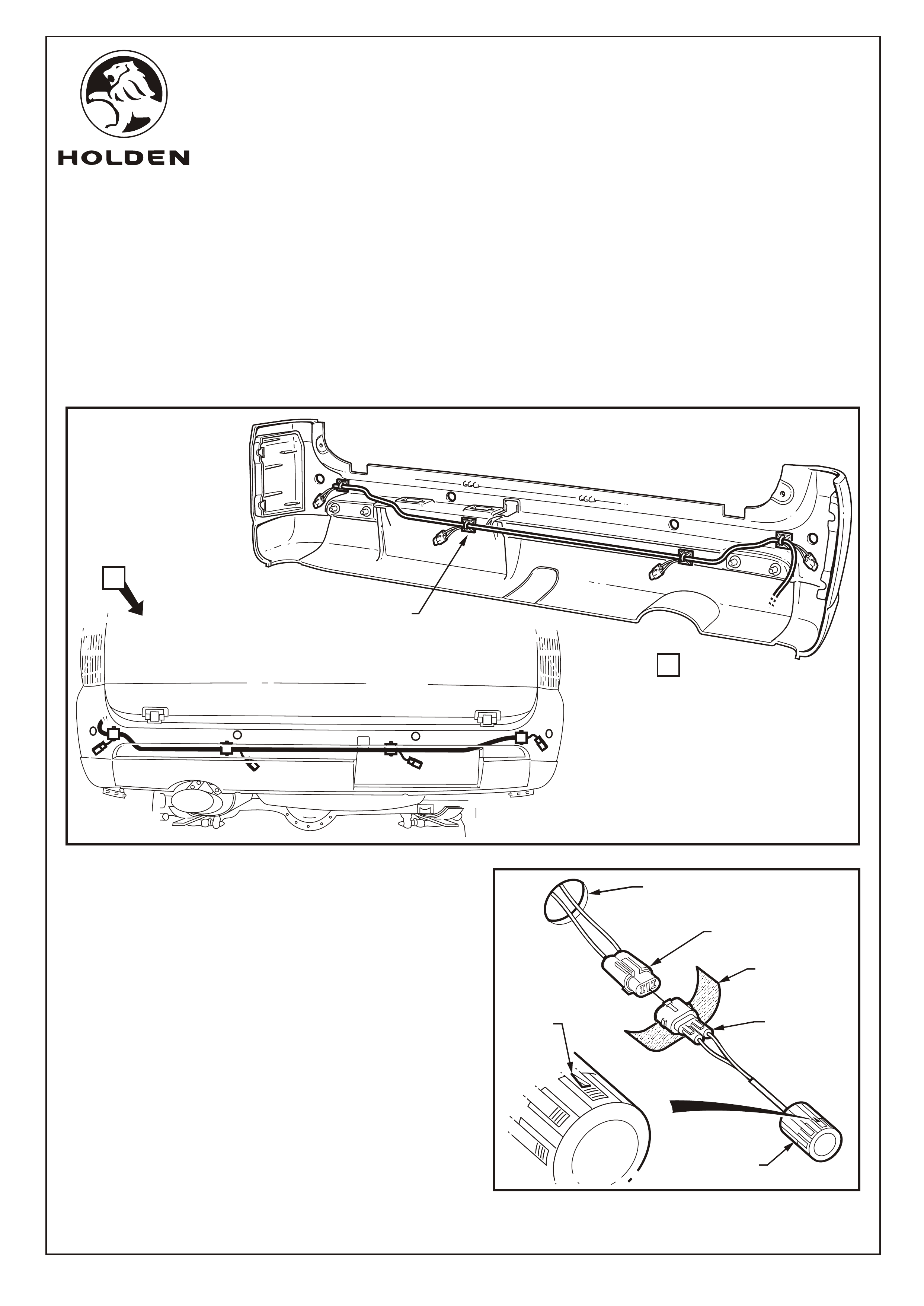
FITTING INSTRUCTIONS: - continued
Refer to Figure 23 for the following:
51. Wipe cable tie securing pad mounting points on the inside of the bumper fascia with high-tech cleaning pad
supplied.
52. Remove protective backing from cable tie attaching pads and press fit to bumper fascia at locations shown.
53. With the aid of an assistant, hold bumper fascia assembly close to vehicle and rout harness along fascia. Loosely tie
strap harness to the securing pads, four places.
FD1166
18JULY03
Refer to Figure 24 for the following:
54. Peel the protective backing off the foam strips supplied
and wrap firmly around each of the four sensor male
connectors.
55. Pass the male connectors with foam through the
bumper fascia holes and with the arrow on the sensor
body facing up, press fit the reverse parking sensors to
sit flush with the fascia.
SENSOR
SENSOR
CONNECTOR
FOAM STRIP
(WRAP AROUND
CONNECTOR)
RPS HARNESS
CONNECTOR
22mm DIA.
BUMPER FASCIA
HOLE
'TOP'
MARK
FIGURE 24
A
A
FIGURE 23
CABLE TIE SECURING
PAD (4 PLACES)
FITTING INSTRUCTIONS FOR
CREW CAB REVERSE PARKING AID SENSOR PACKAGE
COPYRIGHT
Page 13 of 15
HOLDEN LTD
Reproduction in whole or part
prohibited without written approval
Division of HOLDEN Ltd ACN 006 893 232
FITTING INSTRUCTIONS: - continued
56. Fit the rear bumper fascia assembly to the vehicle and
reassemble in the reverse order to removal. Tighten all
rear bumper fascia fasteners to the specified torque.
NOTE: Ensure that the rear bumper fascia assembly
snaps and engages onto the rear bumper fascia
assembly supports.
57. Fix the caution label in a prominent position (above tyre
placard on driver’s side door).
58. Test the reverse parking sensor system for correct
operation as follows:
a. Turn the ignition to the ON position (engine not
running).
b. Place the gear lever in reverse (R). Two beeps from
the buzzer should be heard indicating the system is
activated.
c. From behind the vehicle, walk towards each sensor.
d. The two centre sensors have 3 stages.
e. The two corner sensors only have 1 stage of final
warning. Refer Figure 25.
NOTE: Refer to the owners manual for further
information and trouble shooting.
59. Refit all removed parts in the reverse order to removal
and torque fasteners to specifications.
60. Place fitting instructions in the glovebox.
IMPORTANT: DO NOT paint over the reverse parking
sensor. Ensure the reverse parking sensor remains
clean and free from road grime, mud, car polish etc.
If the sensor or the groove on the sensor surface
becomes contaminated, the performance may be
affected.
FIGURE 25
FD1166
18JULY03
FITTING INSTRUCTIONS FOR
CREW CAB REVERSE PARKING AID SENSOR PACKAGE

COPYRIGHT
Page 14 of 15
HOLDEN LTD
Reproduction in whole or part
prohibited without written approval
Division of HOLDEN Ltd ACN 006 893 232
CREW CAB REVERSE PARKING SENSOR SYSTEM PACKAGE
PARTS LIST
PART NUMBER DESCRIPTION QUANTITY
92148000 REVERSE PARKING SENSOR SYSTEM PACKAGE 1
- REVERSE PARKING SENSOR MAIN HARNESS 1
- REVERSE PARKING SENSOR BUZZER/POWER HARNESS 1
- REVERSE PARKING SENSOR MAIN HARNESS TO BUZZER
HARNESS MALE 2-WAY CONNECTOR 1
- REVERSE PARKING SENSOR MAIN HARNESS TO MODULE
FEMALE 3-WAY CONNECTOR 4
- REVERSE PARKING SENSOR 4
- REVERSE PARKING BUZZER & VELCRO MOUNT PAD 1
- REVERSE PARKING SENSOR MODULE 1
- REVERSE PARKING SENSOR FOAM SEAL 4
- CABLE TIE 10
- HI-TECH CLEANING PAD 2
- VELCRO MOUNT PAD 1
- CABLE TIE MOUNT 7
INSTRUCTION MANUAL 1
FD796 PROOF OF WARRANTY CARD 1
FD 1166 FITTING INSTRUCTIONS 1
FD1166
18JULY03
FITTING INSTRUCTIONS FOR
CREW CAB REVERSE PARKING AID SENSOR PACKAGE
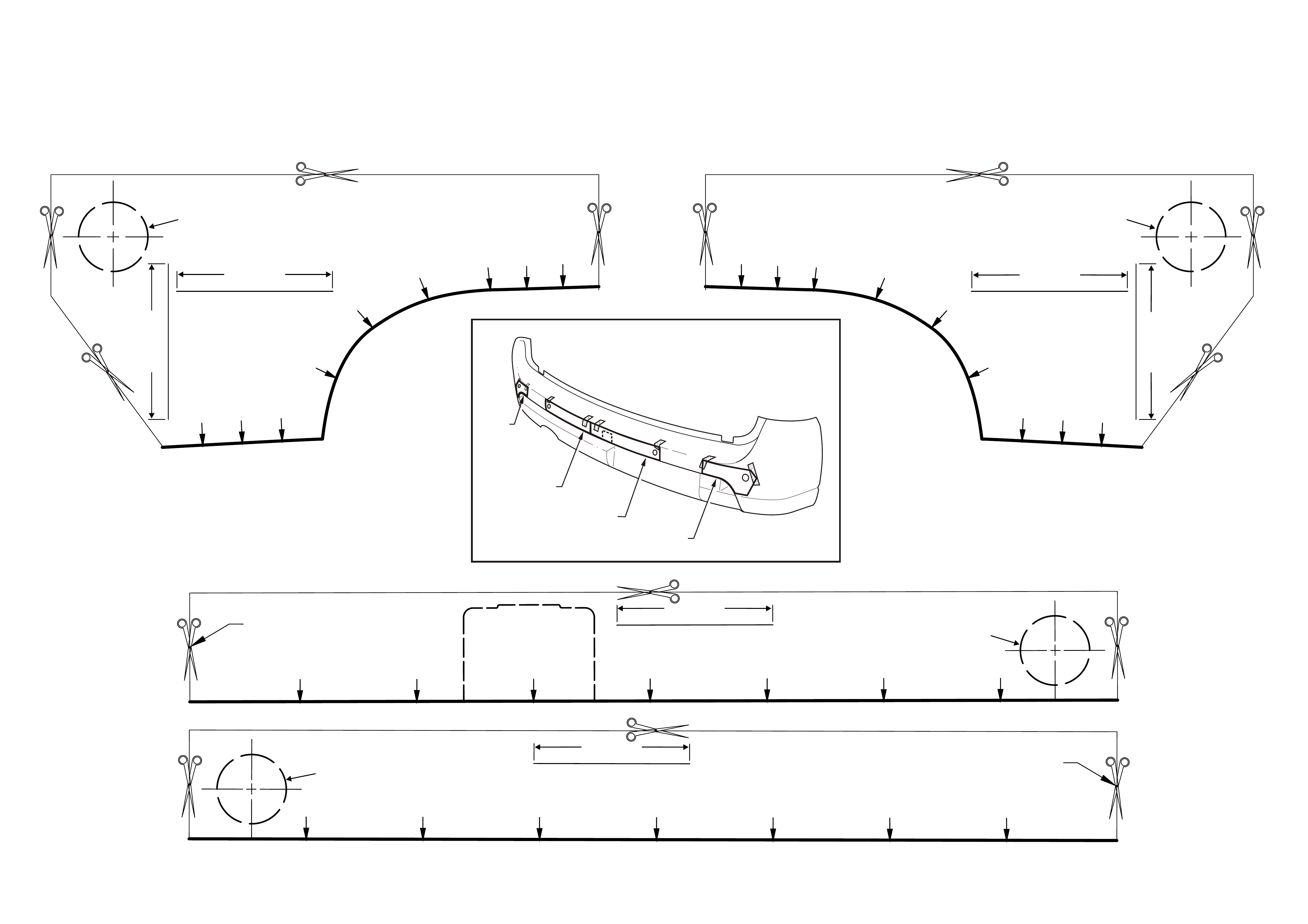
TEMPLATE
4 HEAD SYSTEM
IMPORTANT !!!
ALWAYS CONFIRM LENGTH OF
50mm SCALE MARKERS
BEFORE DRILLING
4 HEAD SYSTEM (RIGHT)
IMPORTANT !!! - CONFIRM LENGTH OF 50MM SCALE MARKERS BEFORE DRILLING
50mm
50mm
22.2 +0.3/ -0
IMPORTANT !!! - CONFIRM LENGTH OF 50MM SCALE MARKERS BEFORE DRILLING
50mm
50mm
22.2 +0.3/ -0
4 HEAD SYSTEM (LEFT)
RIGHT
LEFT
CENTRE LEFT
CENTRE RIGHT
Page 15 of 15
CENTRE OF
BUMPER BAR FACIA 4 HEAD SYSTEM (CENTRE LEFT)
IMPORTANT !!! - CONFIRM LENGTH OF
50MM
SCALE MARKERS BEFORE DRILLING
50mm
22.2 +0.3/ -0
CENTRE OF
BUMPER BAR FACIA
4 HEAD SYSTEM (CENTRE RIGHT)
IMPORTANT !!! - CONFIRM LENGTH OF
50MM
SCALE MARKERS BEFORE DRILLING
50mm
22.2 +0.3/ -0
ALIGN TEMPLATE
OVER SPARE WHEEL
HOIST ACCESS TAB