FITTING INSTRUCTIONS FOR
VZ & WL ROOF MOUNTED DVD PLAYER
FD1207
25OCT04
COPYRIGHT
Reproduction in whole or part
prohibited without written approval
HOLDEN LTD
Division of HOLDEN Ltd ACN 006 893 232
Page 1 of 15
TOOLS REQUIRED:
Phillips Head Screwdriver, Small Flat Bladed Screwdriver, No.10, No.15 Torx Bits, Scissors, Sharp Knife, 4mm, 8mm
Drill Bits, Scriber, Felt Tip Pen, Tape Measure, Guide Wire 800mm in length, Centre Punch, Hammer, Masking Tape,
Safety Glasses, Safety Gloves, Drop Sheet.
Part No. 92176681
IMPORTANT: Before installing the DVD unit in a vehicle with a sunroof, the sunroof must be closed to avoid
damaging the sunroof blind.
FITTING INSTRUCTIONS FOR
VZ & WL ROOF MOUNTED DVD PLAYER
FD1207
25OCT04
COPYRIGHT
Reproduction in whole or part
prohibited without written approval
HOLDEN LTD
Division of HOLDEN Ltd ACN 006 893 232
FITTING INSTRUCTIONS:
1. Turn the ignition to the "OFF" position.
PREPARING VEHICLE FOR WIRING ROUTING
2. Move the passenger front seat to its rearmost position
and angle the seat back rearward.
LOCATING THE DVD MOUNTING
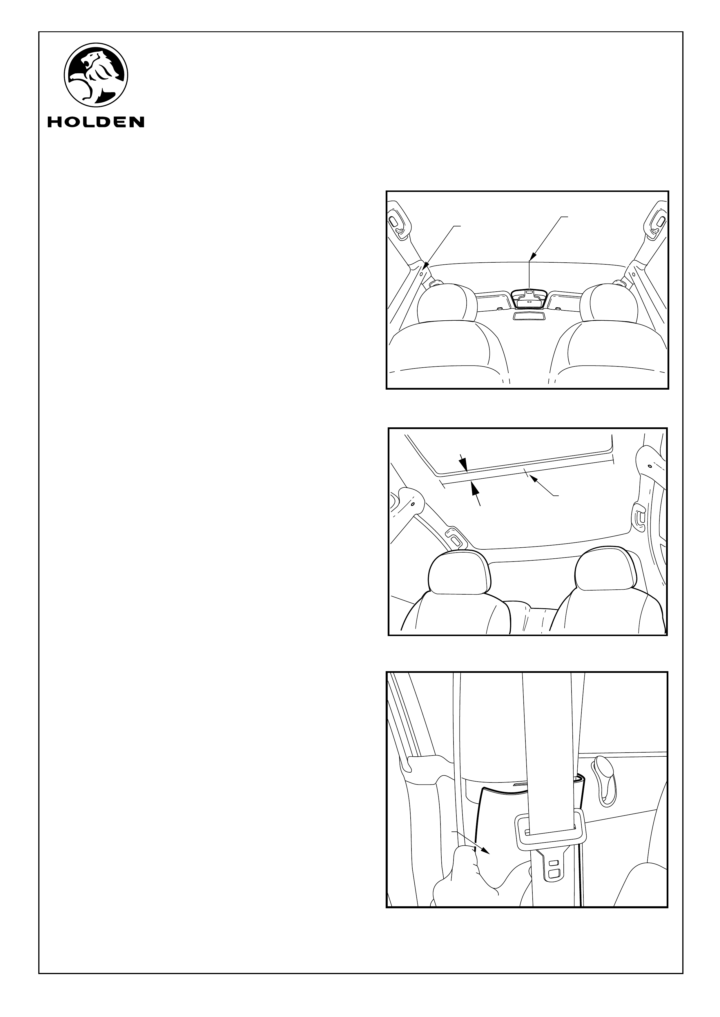
Refer to Figure 1 for the following:
3. Use a tape measure and suitable marking pen to:
(NON SUNROOF VEHICLES)
a. Follow the contour of the roof, measure the total
width between the roof side trims directly above the
“B” pillars retaining screw caps (1) and mark the roof
lining at the half point (2) with a marker pen.
b. Measure 428mm from the centre of the rear edge of
the front sunglass holder to the centre of the roof
following the contour of the roof lining and mark the
position with a marker pen.
(VEHICLES WITH SUN ROOF ONLY)
a. Measure across the width of the sunroof to find the
halfway point (1) of the sunroof and mark the
position 30mm back from the rear edge of the
sunroof opening, mark with a maker pen. Refer to
Figure 2.
4. Pull off the passenger lower “B” pillar trim panel (1).
Refer to Figure 3.
FIGURE 1
Page 2 of 15
FIGURE 2
428mm
1
2
30mm
1
FIGURE 3
1
FITTING INSTRUCTIONS FOR
VZ & WL ROOF MOUNTED DVD PLAYER
FD1207
25OCT04
COPYRIGHT
Reproduction in whole or part
prohibited without written approval
HOLDEN LTD
Division of HOLDEN Ltd ACN 006 893 232
FITTING INSTRUCTIONS: - continued
NOTE: Where a vehicle is fitted with a height adjustable seat
belt, move the adjuster to one end before removing the trim.
When refitting the trim, ensure the trim adjuster is still in the
same position to ensure the seat belt adjuster re-engages
and operates correctly.
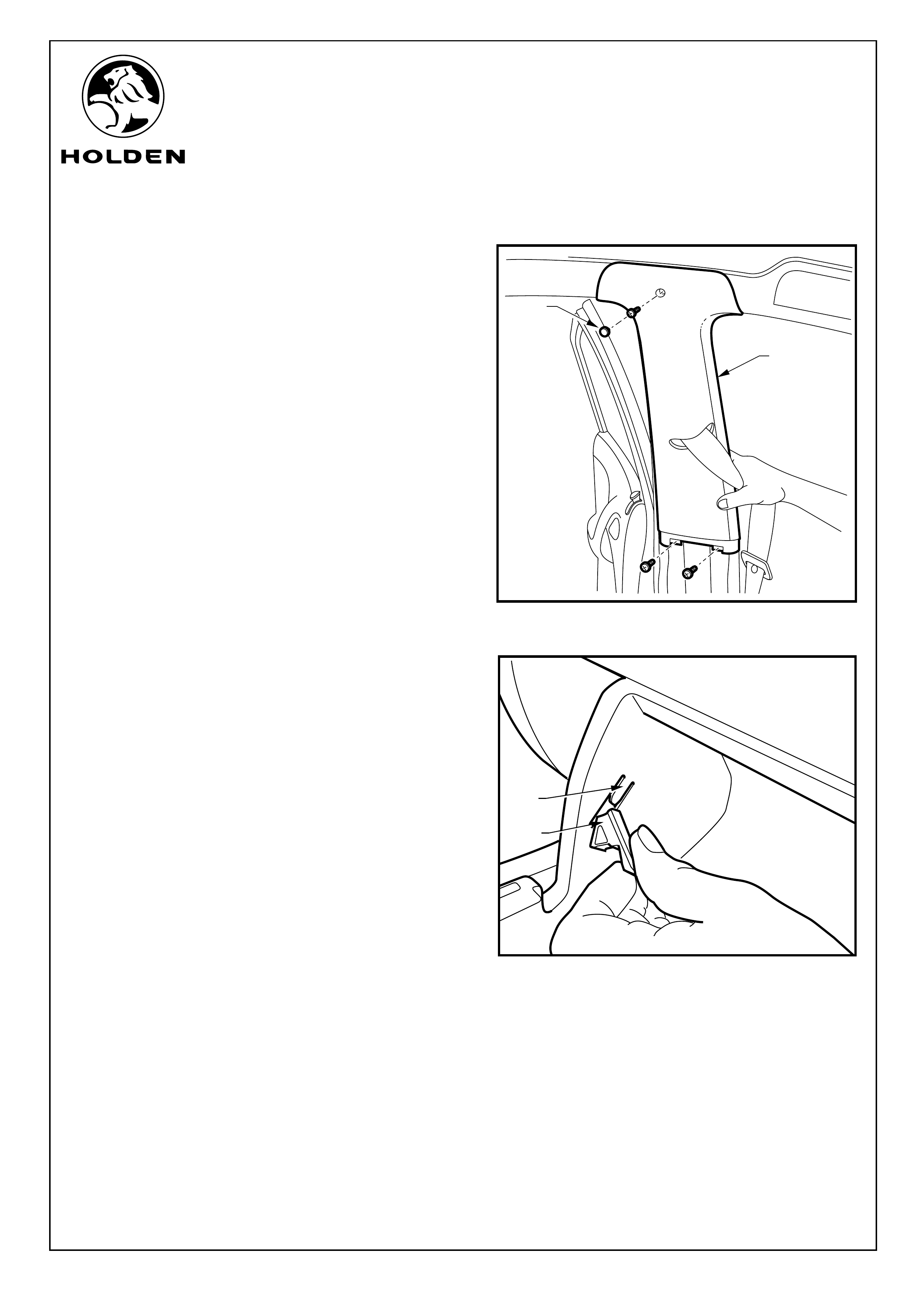
5. Remove passenger side top screw cover (1) and
remove the screws (3 places) holding the "B" pillar
upper trim (2) in position and lower to the floor. Refer to
Figure 4.
Refer to Figure 5 for the following:
6. Open the glovebox and remove the two travel limiting
lugs (1). This is done by carefully raising the rubber tabs
on the limiting lugs and pulling them rearwards. Once
pulled rearwards, gently pull the rubber tabs towards the
center of the glovebox. To release the glovebox, pull
glovebox towards the rear of the vehicle.
NOTE: Care must be taken not to break the tongues (2)
off during glovebox removal.
7. Refit travel limiting lugs and place glovebox to one side.
FIGURE 4
Page 3 of 15
1
2
1
FIGURE 5
2
FITTING INSTRUCTIONS FOR
VZ & WL ROOF MOUNTED DVD PLAYER
FD1207
25OCT04
COPYRIGHT
Reproduction in whole or part
prohibited without written approval
HOLDEN LTD
Division of HOLDEN Ltd ACN 006 893 232
FITTING INSTRUCTIONS: - continued
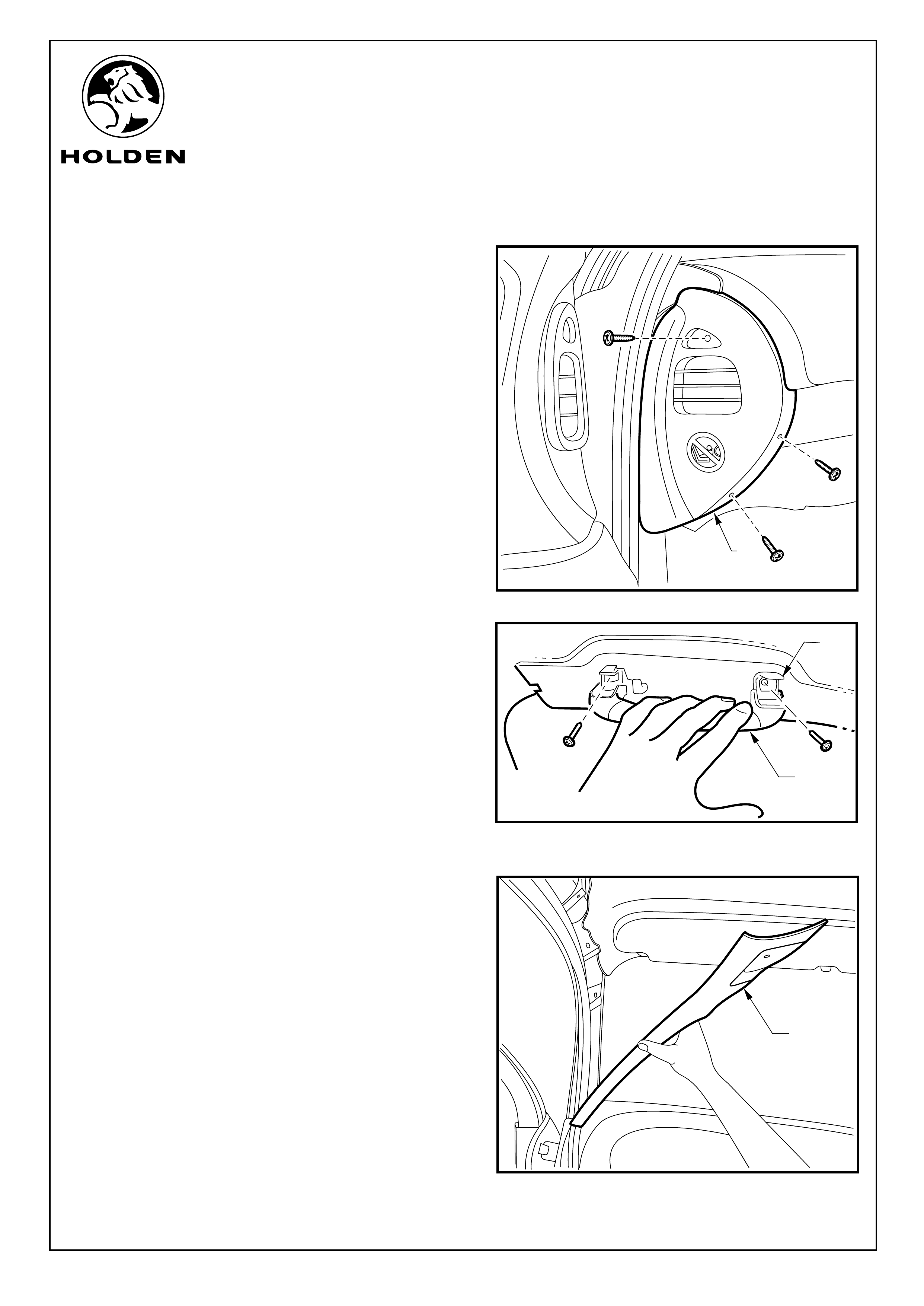
8. Remove the screws (3 places) retaining the passenger
side instrumentation panel end cover (1). Refer to
Figure 6.
9. Open the front roof mounted grab handle (1). Use a
small flat bladed screwdriver to open the screw covers
(2) (2 places), remove the screws and place the handle
aside. Repeat process on the rear passenger grab
handle. Refer to Figure 7.
10. Starting from the top release the retaining clips (3
places) by pulling the “A” pillar trim (1) in towards the
centre of the vehicle to release the three retaining clips
and remove the trim. Refer to Figure 8.
FIGURE 8
Page 4 of 15
FIGURE 7
1
2
1
FIGURE 6
1
FITTING INSTRUCTIONS FOR
VZ & WL ROOF MOUNTED DVD PLAYER
FD1207
25OCT04
COPYRIGHT
Reproduction in whole or part
prohibited without written approval
HOLDEN LTD
Division of HOLDEN Ltd ACN 006 893 232
FIGURE 9
1
2
FITTING INSTRUCTIONS: - continued
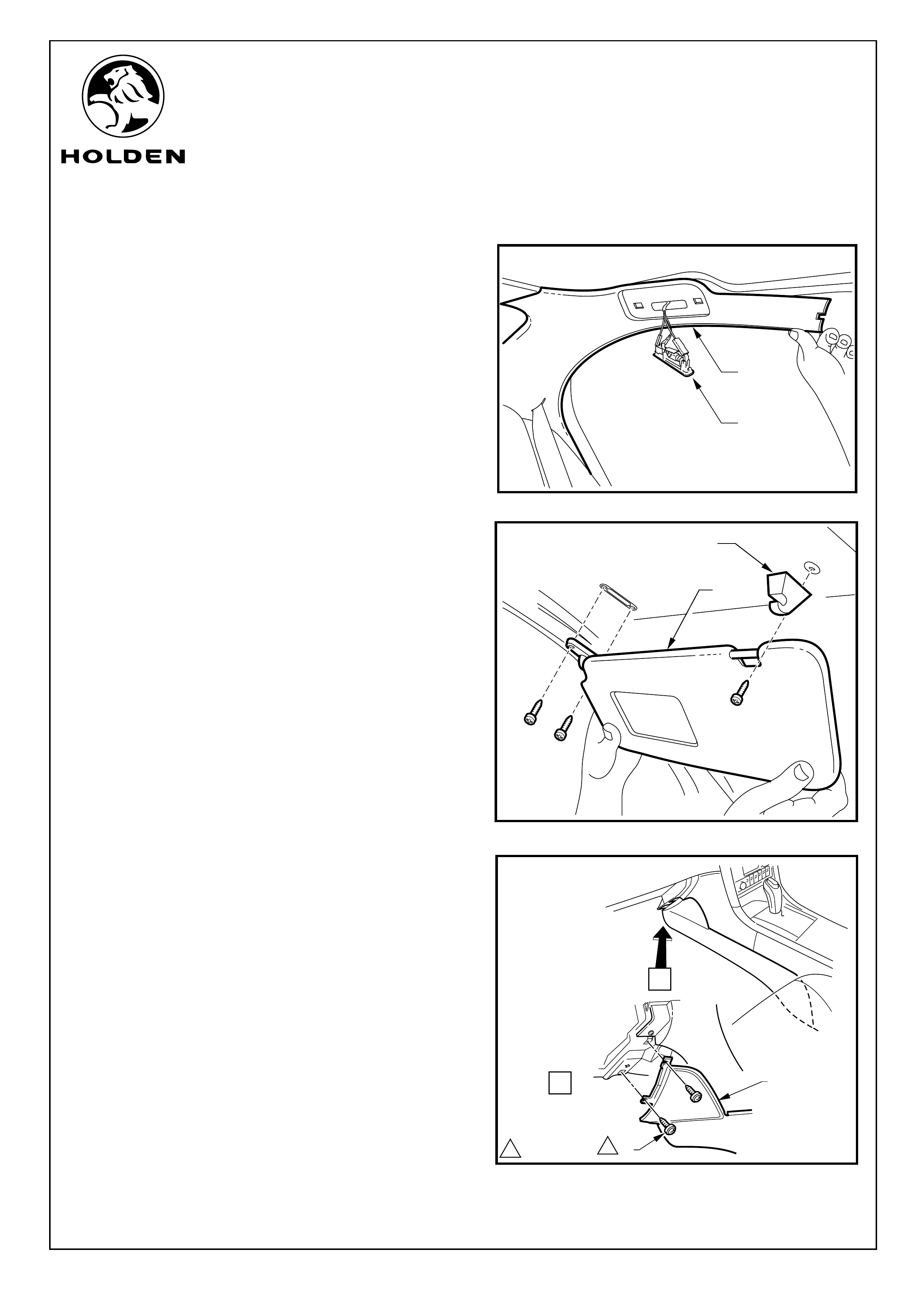
Refer to Figure 9 for the following:
11. Insert a flat bladed screwdriver between the lens and
the “C” pillar roof trim at the globe end of the light fitting
(1) and levering out the light fitting.
12. Unclip the “C” pillar trim (2) along the roof line.
NOTE : Do not remove the "C" pillar trim.
13. Remove the passenger side sun visor (1) and support
(2) . Refer to Figure 10.
14. Remove the screws (1) (2 places) fixing the front end of
the front floor console extension cover (2) on the
passenger side and allow the cover to rotate down to the
floor of the vehicle. Refer to Figure 11.
FIGURE 10
1
2
Page 5 of 15
A
11
2
VIEW
11.0 - 3.0 Nm
A
FIGURE 11
FITTING INSTRUCTIONS FOR
VZ & WL ROOF MOUNTED DVD PLAYER
FD1207
25OCT04
COPYRIGHT
Reproduction in whole or part
prohibited without written approval
HOLDEN LTD
Division of HOLDEN Ltd ACN 006 893 232
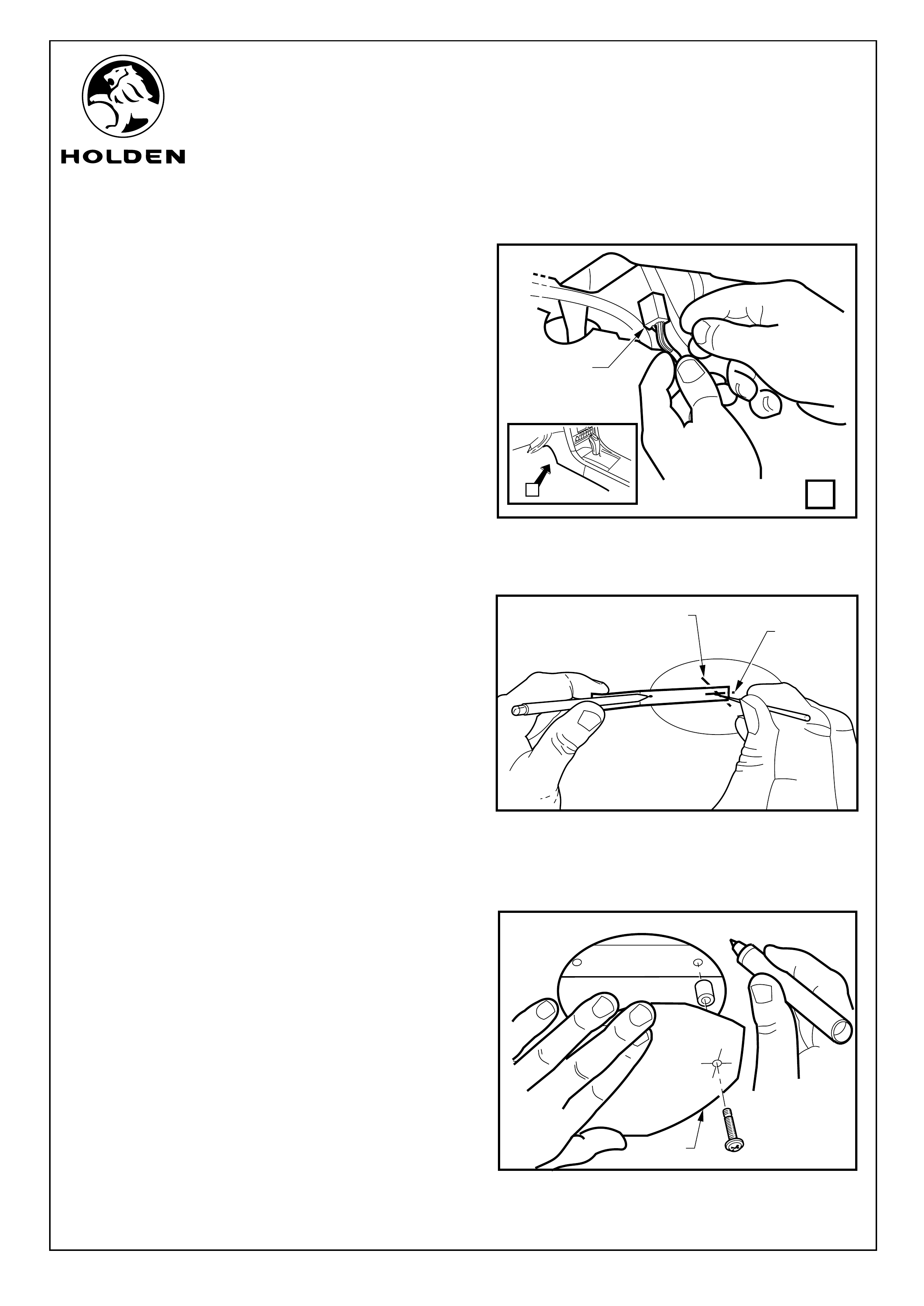
FITTING INSTRUCTIONS: - continued
15. Release the breakout connector (1) for the mobile
phone patch harness from the body harness.
Refer to Figure 12.
NOTE: Hands should be cleaned before working on the roof
lining as the lining will mark easily.
DVD MOUNTING
16. Check the scale on the templates on the last pages of
this instructions. Use a pair of scissors to cut out the
appropriate template for your vehicle (Sunroof, Non
Sunroof). Use the scriber to make the holes in the
template.
NOTE: The template for the sunroof should initially be
cut to the marked "First stage cut".
(NON SUNROOF VEHICLE) FOR VEHICLES WITH
SUNROOF GO TO STEP 19.
Refer to Figure 13 for the following:
17.
a. Use a sharp knife to cut out the circle.
Refer to Figure 14 for the following:
b. Insert screws supplied in the kit into the two holes that
match the two holes in the roof cross rib, put a spacer
on each screw and fit the DVD template in position as
indicated by the DVD template. Do not damage the
template by tightening the screws.
c. Draw around the template (1), then remove and retain
for future use.
Use the circle template from the NON SUNROOF
template page with a scriber in the position marked
and a suitable marker in the other position marked.
Rotate the template around as you would a compass
to draw a 75mm diameter circle in the centre of the
roof identified in step 4.
Page 6 of 15
1
2
FIGURE 12
VIEW
B
B
1
FIGURE 13
FIGURE 14
1
FITTING INSTRUCTIONS FOR
VZ & WL ROOF MOUNTED DVD PLAYER
FD1207
25OCT04
COPYRIGHT
Reproduction in whole or part
prohibited without written approval
HOLDEN LTD
Division of HOLDEN Ltd ACN 006 893 232
FITTING INSTRUCTIONS: - continued
Refer to Figure 15 for the following:
NOTE:
The lines drawn across the front of the template and
along the left hand side of the template are close to the
extremity of the DVD unit so care should be taken
when cutting along these lines on the roof lining.
Using a clean drop sheet is recommended for catching
waste material whilst working.
d. Cut along the line and remove the roof lining material.
e. Refit the DVD template and mark the front and back
mounting holes. Refer to step 17. b. for fitting the DVD
template. Remove the DVD template and centre
punch the two marks on the front and back ribs to
prevent the drill from wandering off the mark.
DVD MOUNTING
(VEHICLES WITH SUN ROOFS ONLY)
Refer to figure 16 for the following:
18. Place the front edge of the DVD template (1) along the
rear edge of the sunroof opening with the centre line on
the template aligned with the half way mark made in step
3. b. and mark the three positions of the mounting holes.
a. Cut out the template to the “second stage cut” line.
Refer to Figure 17 for the following:
b. Realign the template with the three holes
previously marked and draw around the template
with a marker pen.
c. Use a sharp knife to cut around the line.
d. Replace the template back in position and use a
suitable instrument to remark the three mounting
hole positions (1) on the ribs.
IMPORTANT: Make certain that the hole
positions are in the middle of the ribs so that
the bridges will fit in the bottom of the rib and
not contact the sunroof blind.
e. Lightly centre punch the three positions to prevent
the drill from wandering off the mark when drilling
through.
Page 7 of 15
FIGURE 15
FIGURE 16
FIGURE 17
1
1
FITTING INSTRUCTIONS FOR
VZ & WL ROOF MOUNTED DVD PLAYER
FD1207
25OCT04
COPYRIGHT
Reproduction in whole or part
prohibited without written approval
HOLDEN LTD
Division of HOLDEN Ltd ACN 006 893 232
FITTING INSTRUCTIONS: - continued
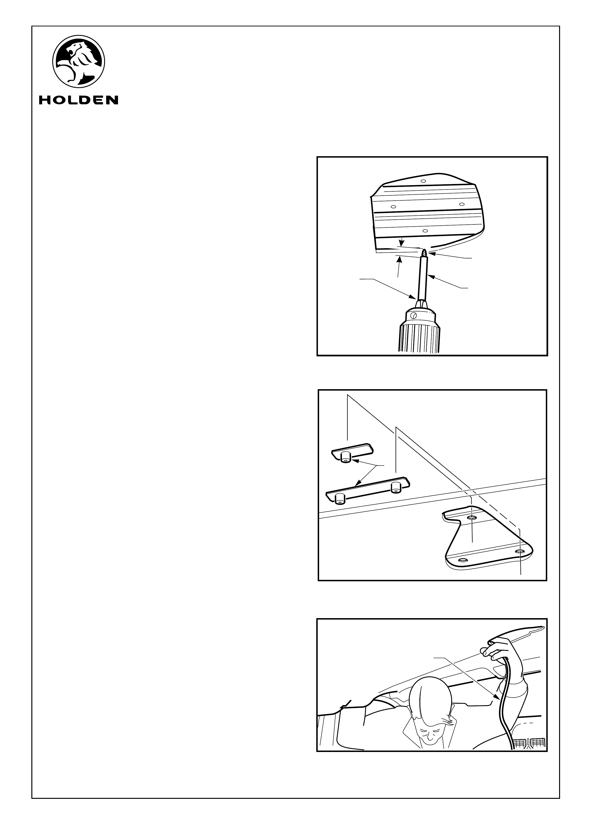
Refer to Figure 18 for the following:
19. Insert the 4mm drill (1) bit into the plastic sleeve (2)
supplied with the kit. Push the sleeve along the drill bit
until the end is 3mm passed the drill tip. Put the drill bit in
the chuck of the drill with the opposite end of the sleeve
up against the jaws of the chuck (3) and tighten the
chuck.
SAFETY NOTE: Wear appropriate eye protection for
this operation.
20. Drill the two holes marked and centre punched on the
roof cross bar for the non sunroof vehicles and three
holes for vehicles with a sun roof. Drill the existing two
holes out on the centre beam (non-sunroof vehicles
only).
(VEHICLES WITH SUN ROOFS ONLY)
a. Fit the large drill sleeve to a 8mm drill bit and fit to
the drill in the same manner as in step 19
maintaining 3mm tip to drill sleeve clearance. Drill
the three holes out to 8mm.
NOTE: If there are bosses present in the rib at the
hole locations drill them out with the 8mm drill bit.
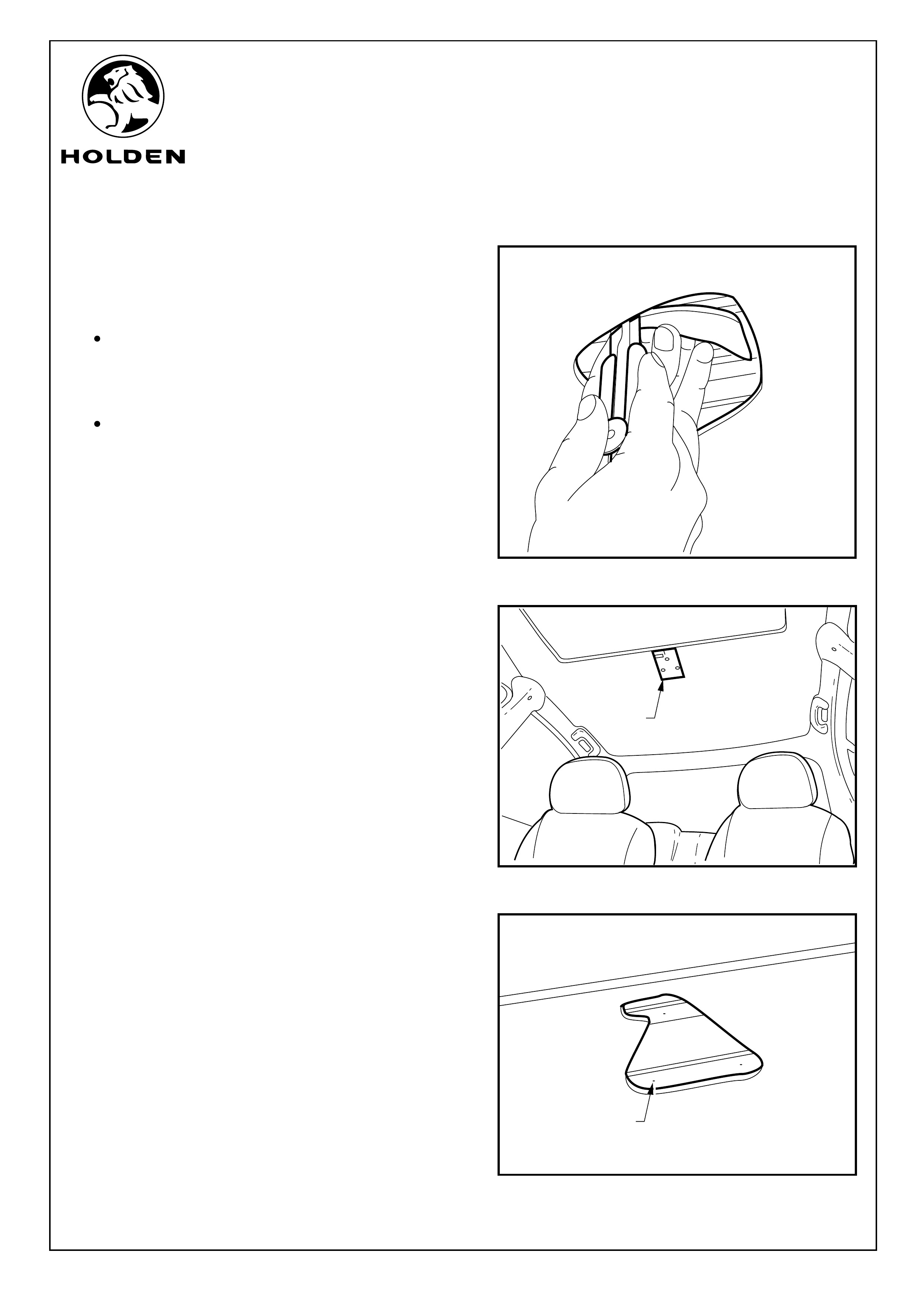
b. Slide the standoff brackets (1) into the sunroof
cavity and drop the standoffs down through the
8mm clearance holes. The standoff bracket with
the two captivated standoffs will go into the rib with
the two holes in and the standoff bracket with the
single standoff in the rib with one hole in. Refer to
Figure 19.
CAUTION: When fitting the DVD mounting bracket
make sure the standoff bracket with the single
standoff is still flush with the bottom of the rib.
NOTE: For vehicles fitted with Holden by Design
sun roofs. Pull the door seals off from around the tops of
the passenger side doors. Release the roof lining from
the side f the vehicle behind the "B" pillar.
21. Pass a semi rigid guide wire (1) through the hole in the
roof lining across to the passenger side “B” pillar.
Refer to Figure 20.
CAUTION: Sharp edges maybe present, the use of
safety gloves is recommended.
FIGURE 20
Page 8 of 15
1
FIGURE 18
1
2
3
3mm
FIGURE 19
1
FITTING INSTRUCTIONS FOR
VZ & WL ROOF MOUNTED DVD PLAYER
FD1207
25OCT04
COPYRIGHT
Reproduction in whole or part
prohibited without written approval
HOLDEN LTD
Division of HOLDEN Ltd ACN 006 893 232
FITTING INSTRUCTIONS: - continued
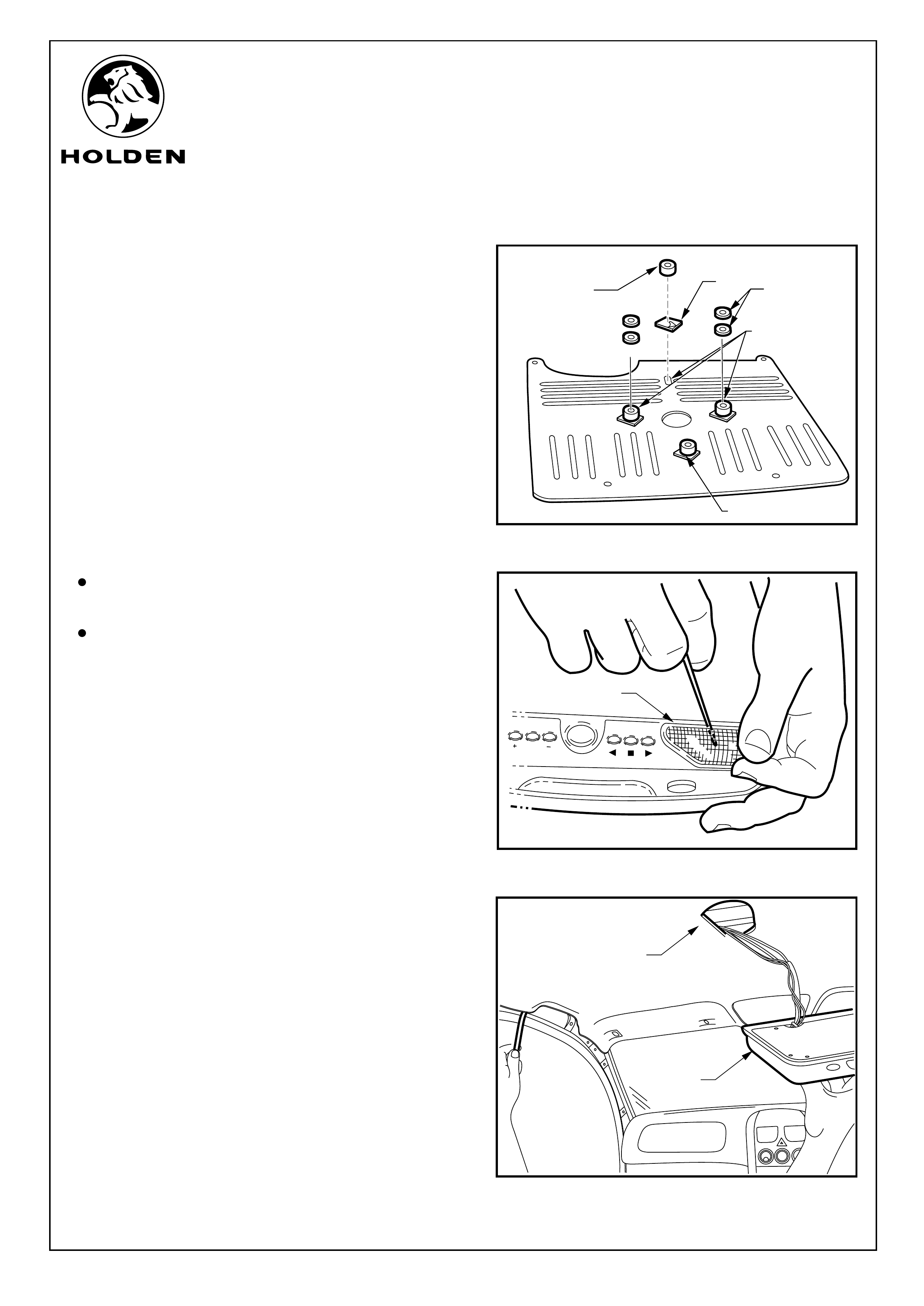
Refer to Figure 21 for the following:
22. Peel off one side of the double sided tape (1) and press
firmly down over the mounting holes (3 and also 4 for
vehicles without a sunroof) on the top surface of the
DVD mounting bracket. The bottom side of the mounting
bracket has two locating lugs diagonally apposed to
each other, the top surface is smooth.
23. Peel off the backing tape from the double sided tape
over the four holes in the mounting bracket and align the
spacers (2) with the mounting holes on the top surface of
the DVD mounting bracket (3), use the scriber to clear
the holes.
NOTE:
Two washers (5) are taped to the top of the two middle
spacers.
Use the three spacers with an internal hole diameter of
8mm for a vehicle fitted with a sunroof and the spacers
with the 4mm internal hole diameter for vehicle without a
sunroof.
Refer to Figure 22 for the following:
24. Use small flat bladed screwdriver to remove the two
DVD light lenses (1).
25. Place the DVD player (screen downwards)on the
armrest of the front floor centre console. Tape the DVD
cables to the guide wire.
NOTE: Before preceding with step 26 read through
instructions to step 28.
Refer to Figure 23 for the following:
26. With the aid of an assistant, raise the DVD (1) up to the
hole in the roof lining (2) whilst feeding the DVD
connections up through the roof lining and carefully
pulling the wires out the passenger side “B” pillar area.
NOTE: When passing the harness through the
headlining, make sure the ribbon wires are flat and
running in between the ribs in the sunroof casement.
Page 9 of 15
FIGURE 21
1
2
3
FIGURE 23
1
2
4
FRONT
OF
DVD
PRESS. PRESS.
POWER. POWER.
PICT.
PICT.
1
FIGURE 22
5
FITTING INSTRUCTIONS FOR
VZ & WL ROOF MOUNTED DVD PLAYER
FD1207
25OCT04
COPYRIGHT
Reproduction in whole or part
prohibited without written approval
HOLDEN LTD
Division of HOLDEN Ltd ACN 006 893 232
FITTING INSTRUCTIONS: - continued
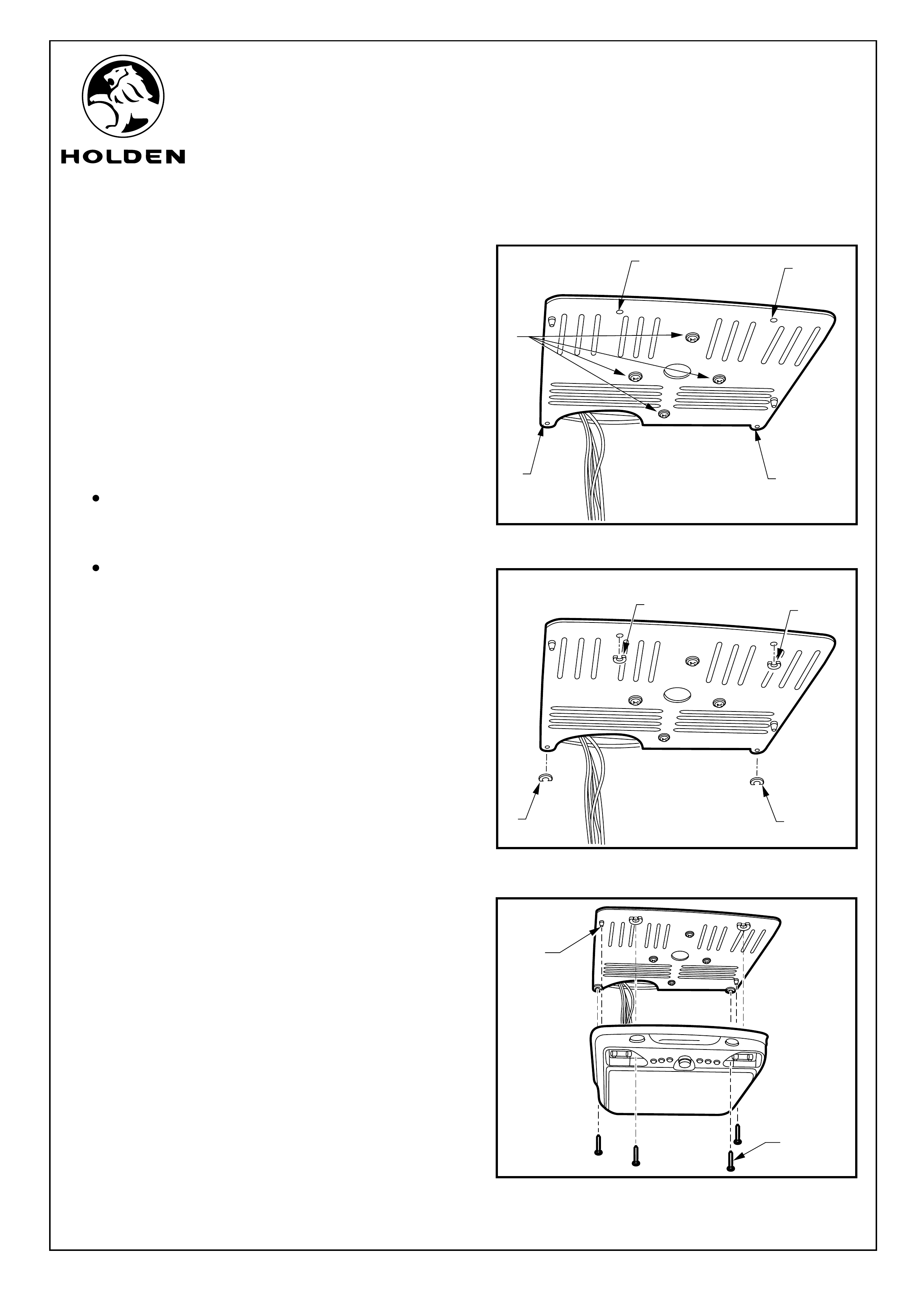
IMPORTANT: Prior to installing mounting screws, ALWAYS
ensure that spacers and washers are installed to avoid
damage to the vehicle roof. Do not pre-install the mounting
screws or thread tap the mounting holes as this will increase
the risk of roof damage.
27. Fit the DVD mounting bracket to the vehicle using
screws provided (1) adjust and tighten. Push the scriber
through the four DVD mounting holes (2) in the bracket
to make holes in the roof lining. Refer to Figure 24.
NOTE:
Adjust the mounting bracket by pushing to the rear of
the vehicle and ensure the bracket is square with the
vehicle before tightening.
Do not push the scriber past the head liner into the
steel roof.
28. Remove the backing tap from the back of the cut
washers and position the washers around the threaded
DVD mounting holes, the straight edge should be
parallel to the edge of the mounting plate. Refer to
Figure 25.
29. Align the DVD with the alignment lugs (1) on the
mounting bracket. Use the four Torx screws provided (2)
in the DVD fixing points two inside each of the light
recesses and two screws in the forward holes.
Refer to Figure 26.
30. Reinstall lens covers and fit rubber plugs in the forward
screw holes.
FIGURE 24
22
2
2
1
Page 10 of 15
FIGURE 25
11
1
1
FIGURE 26
1
2
FITTING INSTRUCTIONS FOR
VZ & WL ROOF MOUNTED DVD PLAYER
FD1207
25OCT04
COPYRIGHT
Reproduction in whole or part
prohibited without written approval
HOLDEN LTD
Division of HOLDEN Ltd ACN 006 893 232
FITTING INSTRUCTIONS: - continued
NOTE: The guide wire should be used to pass the five-pin
power wire through the roof lining from the "A" pillar to the
DVD connectors at the "B" pillar.
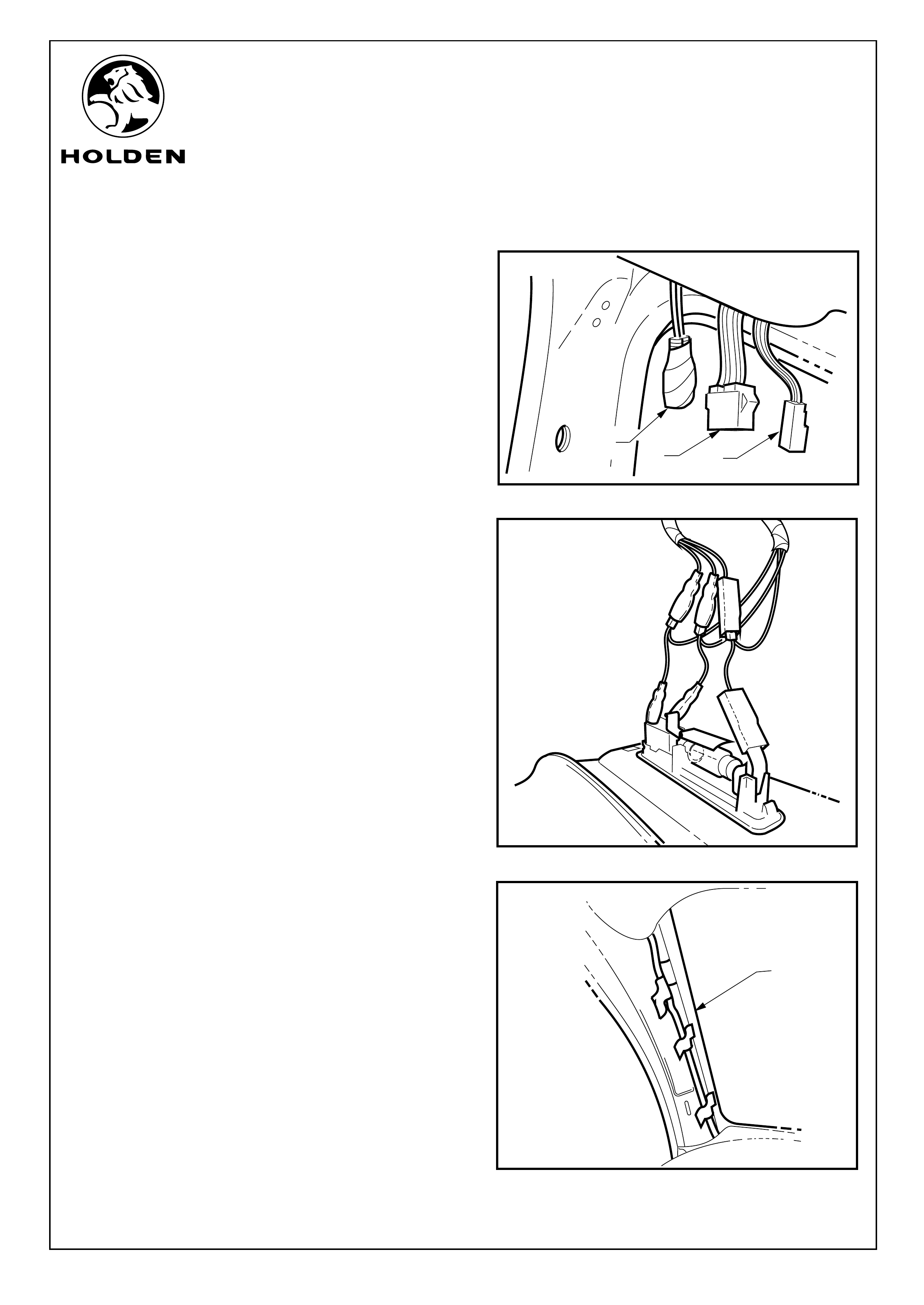
31. Connect the five-pin DVD connector to the power wiring
harness (1) and connect the lighting harness to the
lighting harness connector (2).
Refer to Figure 27.
NOTE: The connectors (3), are taped up, this tape
should not removed.
OPTIONAL FM MODULATOR
If the optional FM modulator has been purchased, the
audio wire should be run along the same route and at the
same time as the power lead to the base of the "A" pillar,
see steps 33-35.
NOTE: Remove the tape from the connectors (3) and
connect the audio lead. Refer to Figure 28.
ROUTING WIRING
32. Connect the DVD lighting harness to the female
connectors of the rear passenger side lighting harness,
then connect the female DVD lighting connectors onto
the male interior light connector. Refer to Figure 28.
33. Run the power lead to the front of the Vehicle and down
the vehicle's “A” pillar (1). Apply tape in three places
along the “A” pillar. Refer to Figure 29.
FIGURE 27
3
2
1
FIGURE 29
FIGURE 28
1
Page 11 of 15
FITTING INSTRUCTIONS FOR
VZ & WL ROOF MOUNTED DVD PLAYER
FD1207
25OCT04
COPYRIGHT
Reproduction in whole or part
prohibited without written approval
HOLDEN LTD
Division of HOLDEN Ltd ACN 006 893 232
FIGURE 30
1
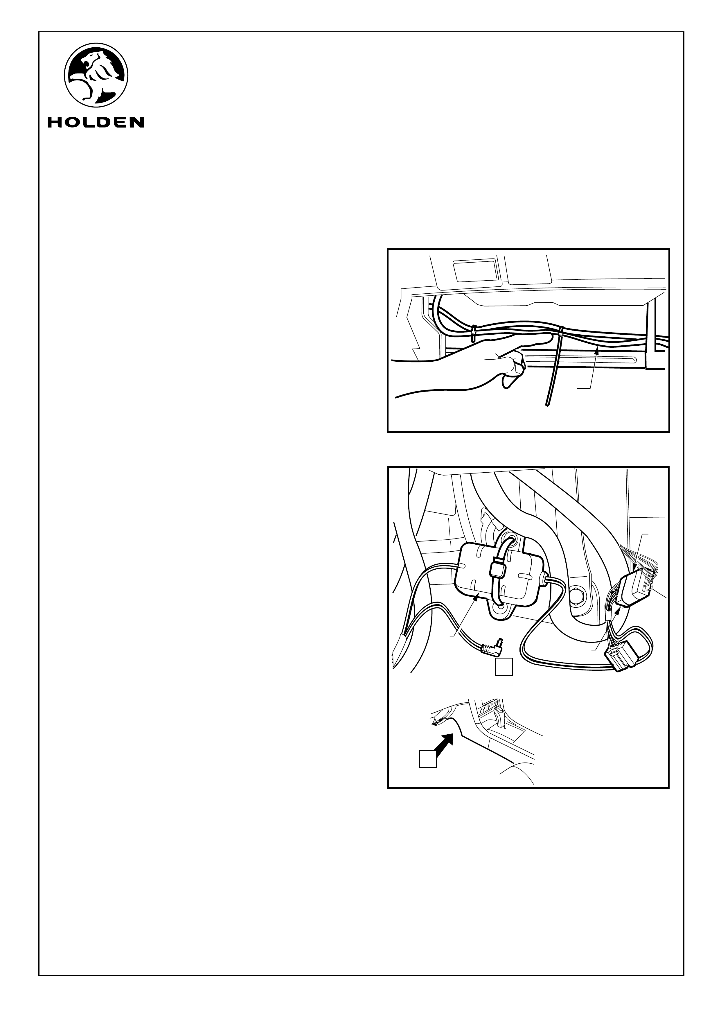
FITTING INSTRUCTIONS: - continued
Refer to Figure 30 for the following:
34. Run the power wires (1) through the vehicle dashboard
behind the glovebox and into the cavity between the
dashboard and the front floor mounted console.
NOTE: The wires must not cross each other when
passing across the back of the glovebox or the wire will
interfere with the glovebox operation.
35. Cable tie in two places to prevent movement.
Refer to Figure 31 for the following:
36. Cable tie the in-line filter (1) in the cavity.
37. Connect the power connector (2) into the body harness
mobile phone breakout connector (3). Check the DVD
operation.
38. Carefully peel off the protective clear plastic film from the
DVD viewing screen.
39. Tuck the connectors at the “B” pillar into the roof cavity
forward of the roof cross bar.
40. Tuck the harness into roof cavity.
41. Refit the interior trim and the grab handle.
42. Refit all remaining parts removed in reverse order.
43. Put fitting instructions in glovebox.
FIGURE 31
A
A
VIEW
2
3
1
Page 12 of 15

FITTING INSTRUCTIONS FOR
VZ & WL ROOF MOUNTED DVD PLAYER
FD1207
25OCT04
COPYRIGHT
Reproduction in whole or part
prohibited without written approval
HOLDEN LTD
Division of HOLDEN Ltd ACN 006 893 232
PARTS LIST
PART NUMBER DESCRIPTION QUANTITY
92176681 ROOF MOUNTED DVD SYSTEM - NON SUNROOF 1
DVD UNIT 1
SMALL PARTS KIT 1
DRILL SLEEVE - 8MM 1
DRILL SLEEVE - 4MM 1
DOUBLE SIDED TAPE 1
SCREW - SECURITY 4
CAP 2
CABLE TIES 4
WASHERS - CUT 4
SMALL PARTS KIT NON SUNROOF 1
SCREW - SELF TAPPING 4
SPACER 4
WASHERS 4
SMALL PARTS KIT SUNROOF 1
BRACKET- -STANDOFF SINGLE 1
BRACKET - STANDOFF DOUBLE 1
SLEEVE 3
FD1281 OWNER'S HANDBOOK 1
FD1207 FITTING INSTRUCTIONS 1
FD796 PROOF OF WARRANTY CARD 1
NOT PROVIDED IN THIS KIT BUT AVAILABLE SEPARATELY:
92176736 HEADPHONE KIT 1
FM MODULATOR 1
92172089 DVD - REMOTE CONTROL 1
DVD - MOUNTING BRACKET 1
DVD - WIRING HARNESS 1
SIDE LIGHT - WIRING HARNESS 1
SCREW - M4x12mm 3
92176737
PARTS LISTPARTS LIST
Page 13 of 15
FITTING INSTRUCTIONS FOR
VZ & WL ROOF MOUNTED DVD PLAYER
FD1207
25OCT04
COPYRIGHT
Reproduction in whole or part
prohibited without written approval
HOLDEN LTD
Division of HOLDEN Ltd ACN 006 893 232
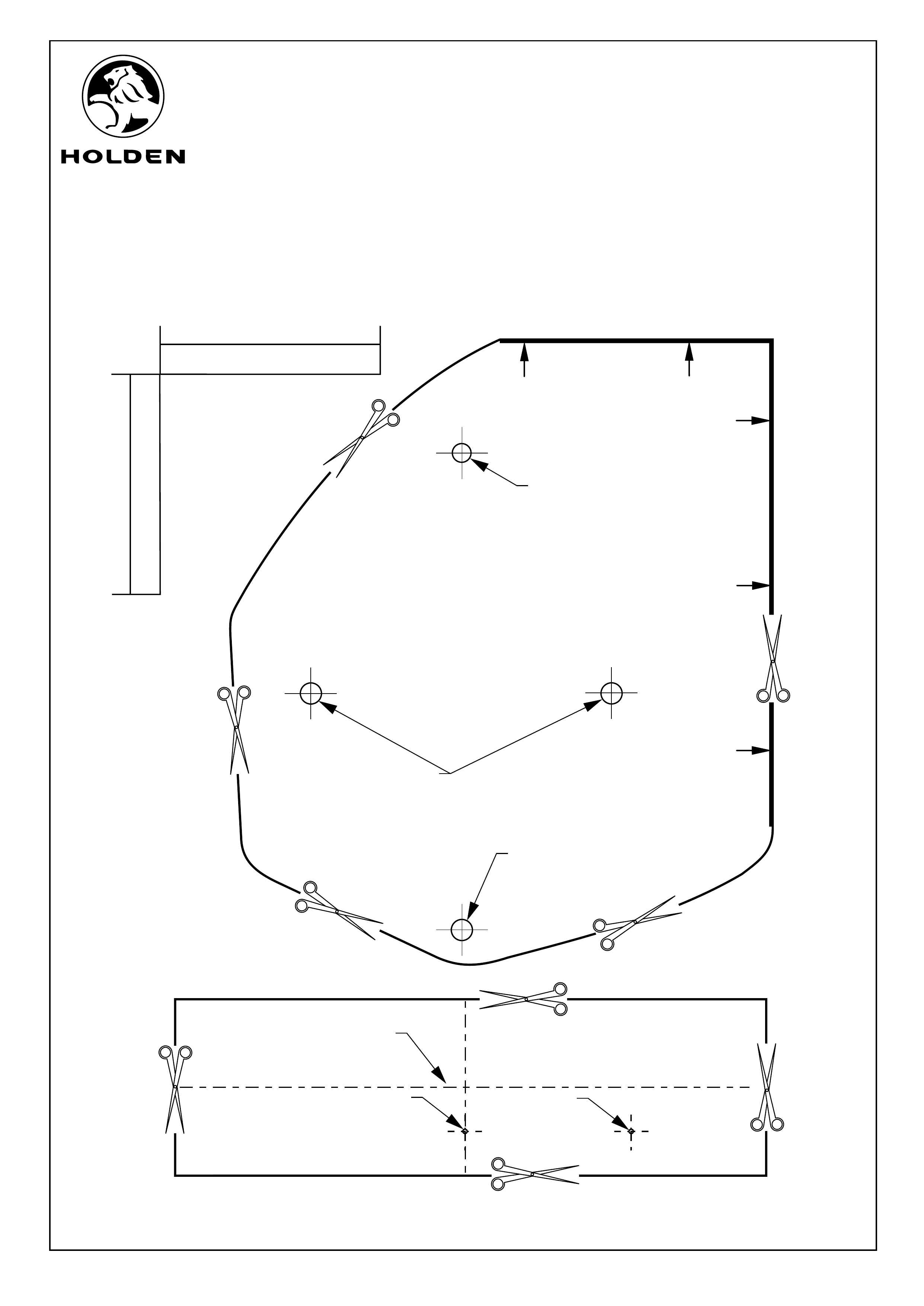
50 MM
50 MM
FRONT
OF VEHICLE
PARALLEL TO PASSENGER SIDE OF VEHICLE
ROOF TEMPLATE
NON SUN ROOF
ROOF CIRCLE TEMPLATE
INSERT PEN INSERT
SCRIBER
Page 14 of 15
ALIGN WITH EXISTING HOLES
IN ROOF CROSS BAR
MARK THE HOLE POSITION
ON THE ROOF CROSS BAR
MARK THE HOLE POSITION
ON THE ROOF CROSS BAR
SCALE
TEMPLATES FOR
NON SUNROOF VEHICLE
Strengthen template
by folding in half
FITTING INSTRUCTIONS FOR
VZ & WL ROOF MOUNTED DVD PLAYER
FD1207
25OCT04
COPYRIGHT
Reproduction in whole or part
prohibited without written approval
HOLDEN LTD
Division of HOLDEN Ltd ACN 006 893 232
Page 15 of 15
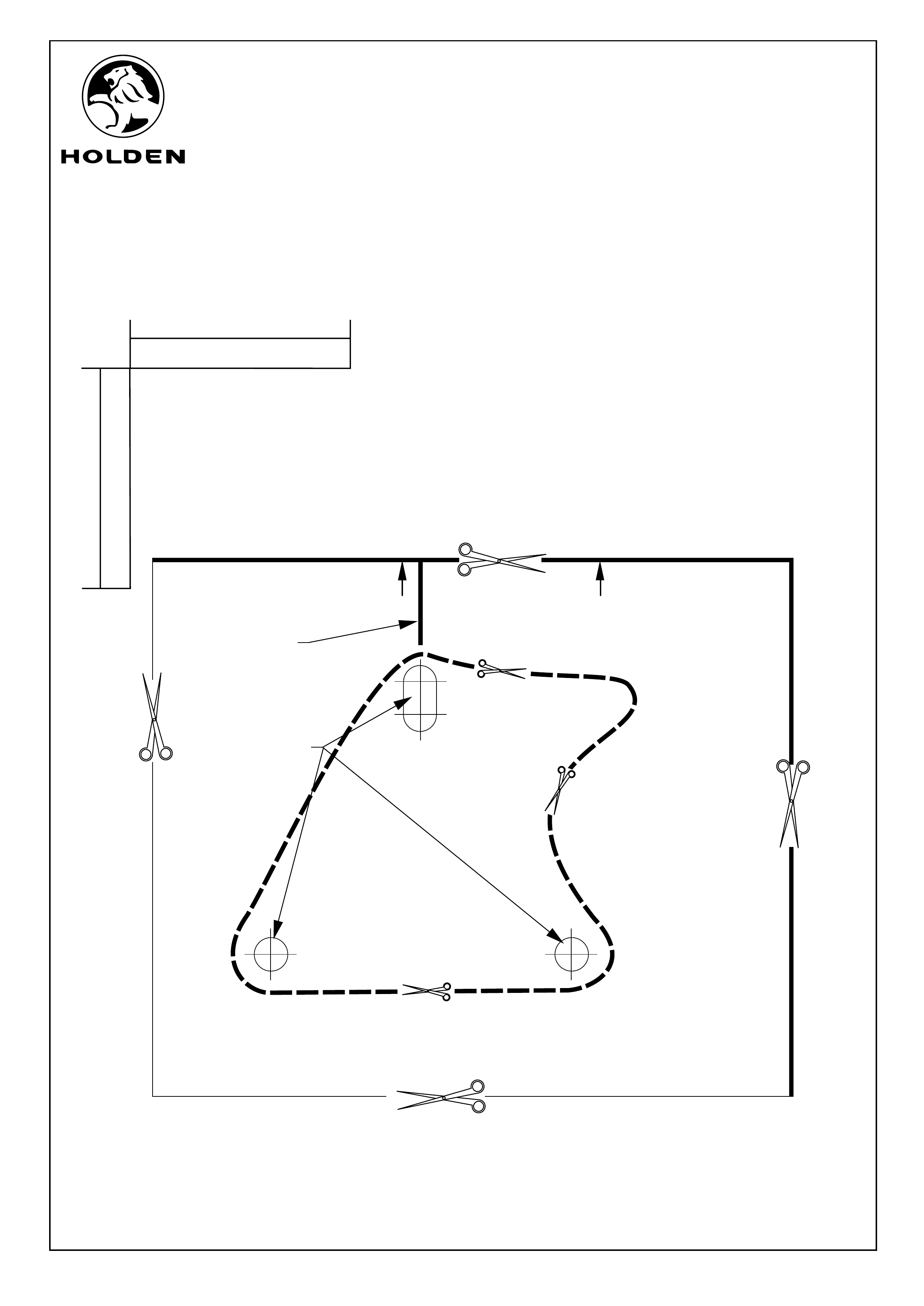
FRONT
OF VEHICLE
ALIGN
WITH MARK
ON ROOF
DRILLING TEMPLATE FOR VEHICLE
WITH SUNROOF
MARK THE
THREE HOLE
POSITIONS
50 MM
50 MM
SECOND STAGE CUT
SECOND STAGE CUT
SECOND STAGE
CUT
FIRST STAGE CUT
FIRST STAGE CUT
FIRST STAGE CUT
FIRST STAGE CUT
SCALE
TEMPLATE FOR
SUNROOF VEHICLE