FITTING INSTRUCTIONS FOR
VY, VY2 & VZ COMMODORE
BLUETOOTH PHONE KIT
COPYRIGHT
Reproduction in whole or part
prohibited without written approval
FD1208
03SE04
HOLDEN LTD
Division of HOLDEN Ltd ACN 006 893 232
1
2
3
5
6
4
3
4
Page 1 of 8
Part No. 92166680
TOOLS REQUIRED:
Phillips Head Screwdriver, Trim Removal Tool, Side Cutters.
FITTING INSTRUCTIONS:
1. Turn ignition to the "OFF" position.
2. Move both front seats to their rear most position.
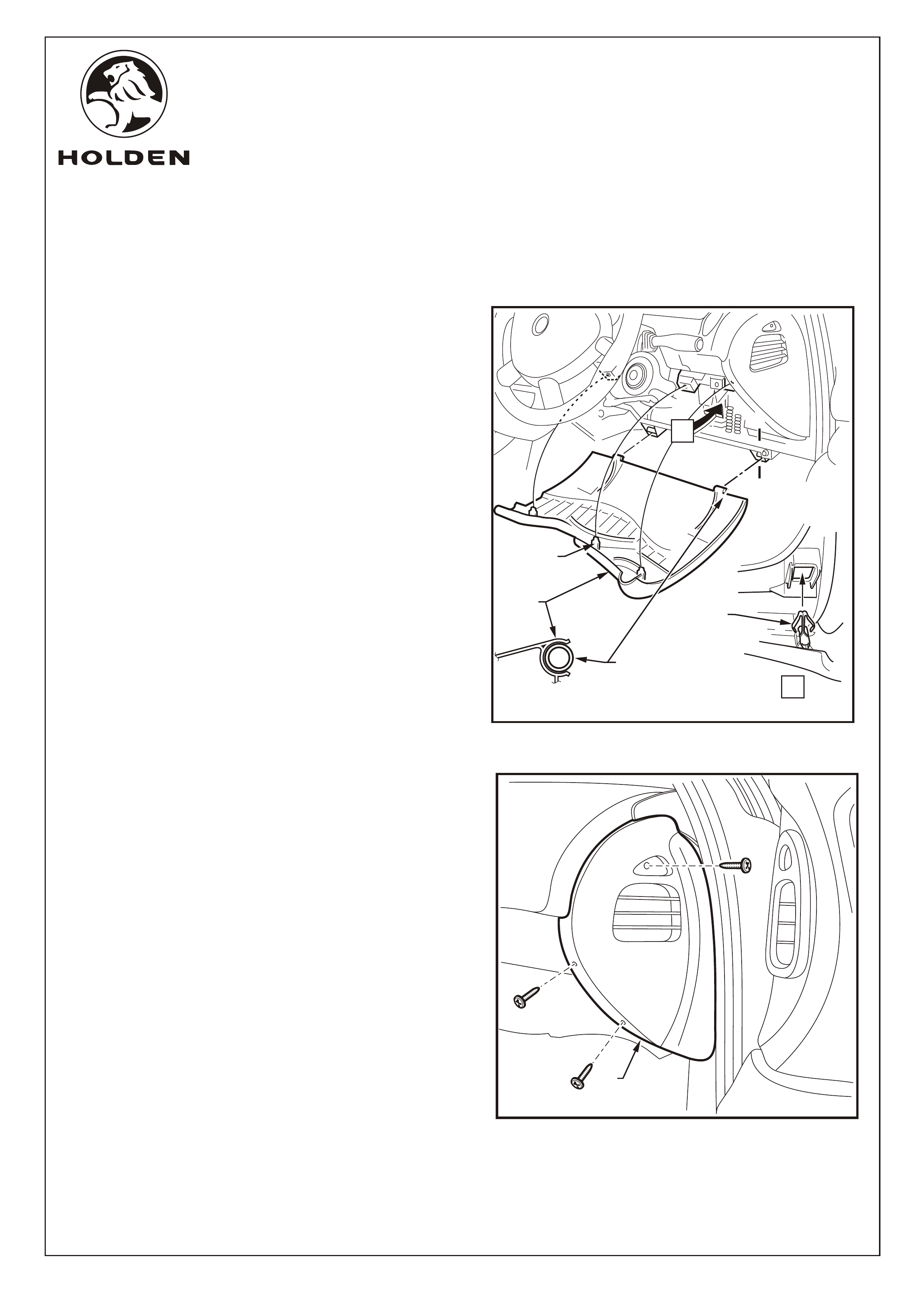
Refer to Figure 1 for the following:
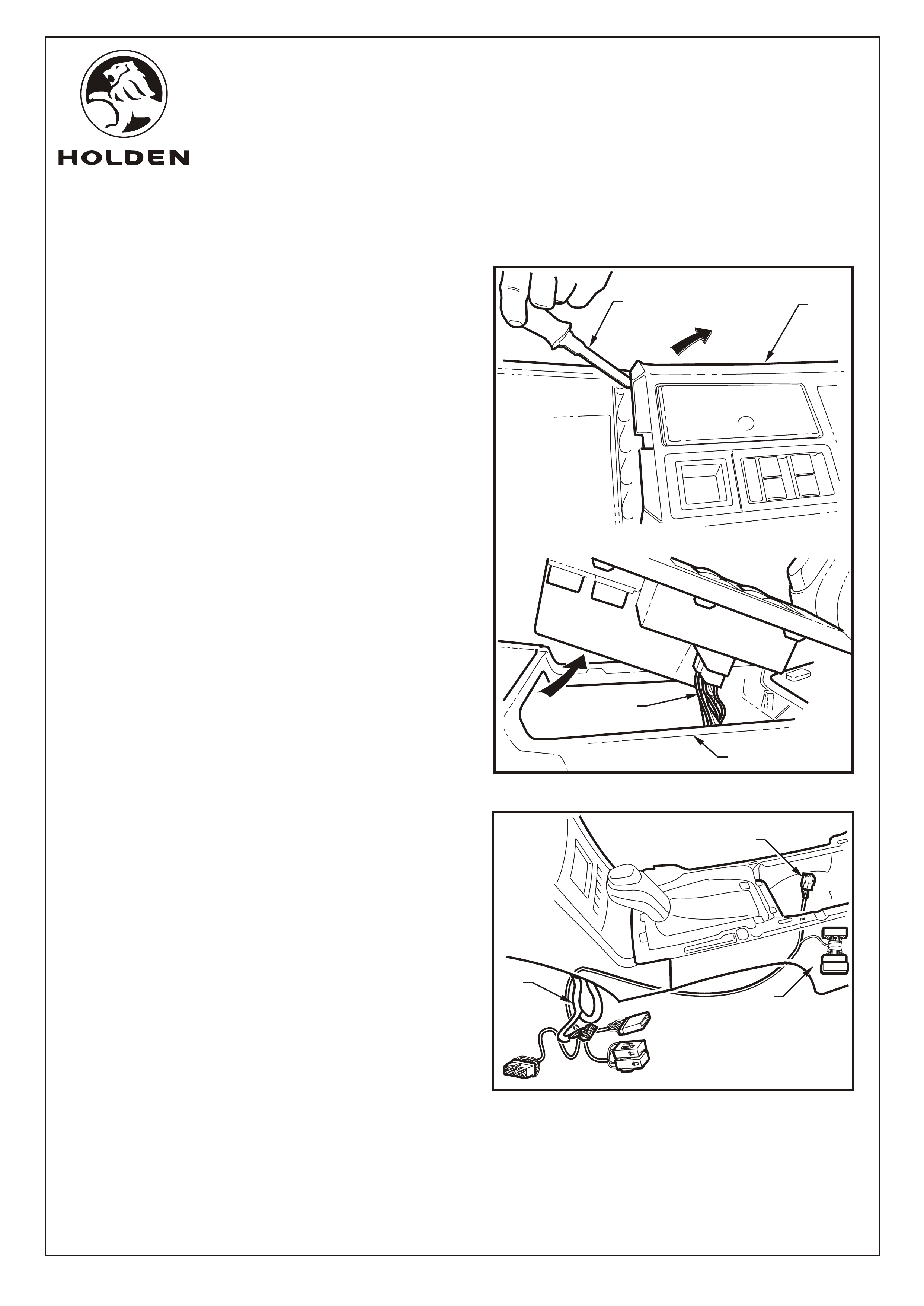
3. Open the glovebox and remove the two travel limiting
lugs (1). This is done by carefully raising the rubber tabs
on the limiting lugs and pulling them rearwards. Once
pulled rearwards, gently pull the rubber tabs towards
the center of the glovebox. To release the glovebox, pull
glovebox towards the rear of the vehicle.
NOTE: Care must be taken not to break the tongues (2)
off during travel limiting lug removal.
4. Refit travel limiting lugs and place glovebox to one side.
1
FIGURE 1
FITTING INSTRUCTIONS FOR
VY, VY2 & VZ COMMODORE
BLUETOOTH PHONE KIT
COPYRIGHT
Reproduction in whole or part
prohibited without written approval
FD1208
03SE04
HOLDEN LTD
Division of HOLDEN Ltd ACN 006 893 232
1
2
3
5
6
4
3
4
Page 2 of 8
FIGURE 2
A
11.0 - 3.0 Nm
A
11
2
VIEW
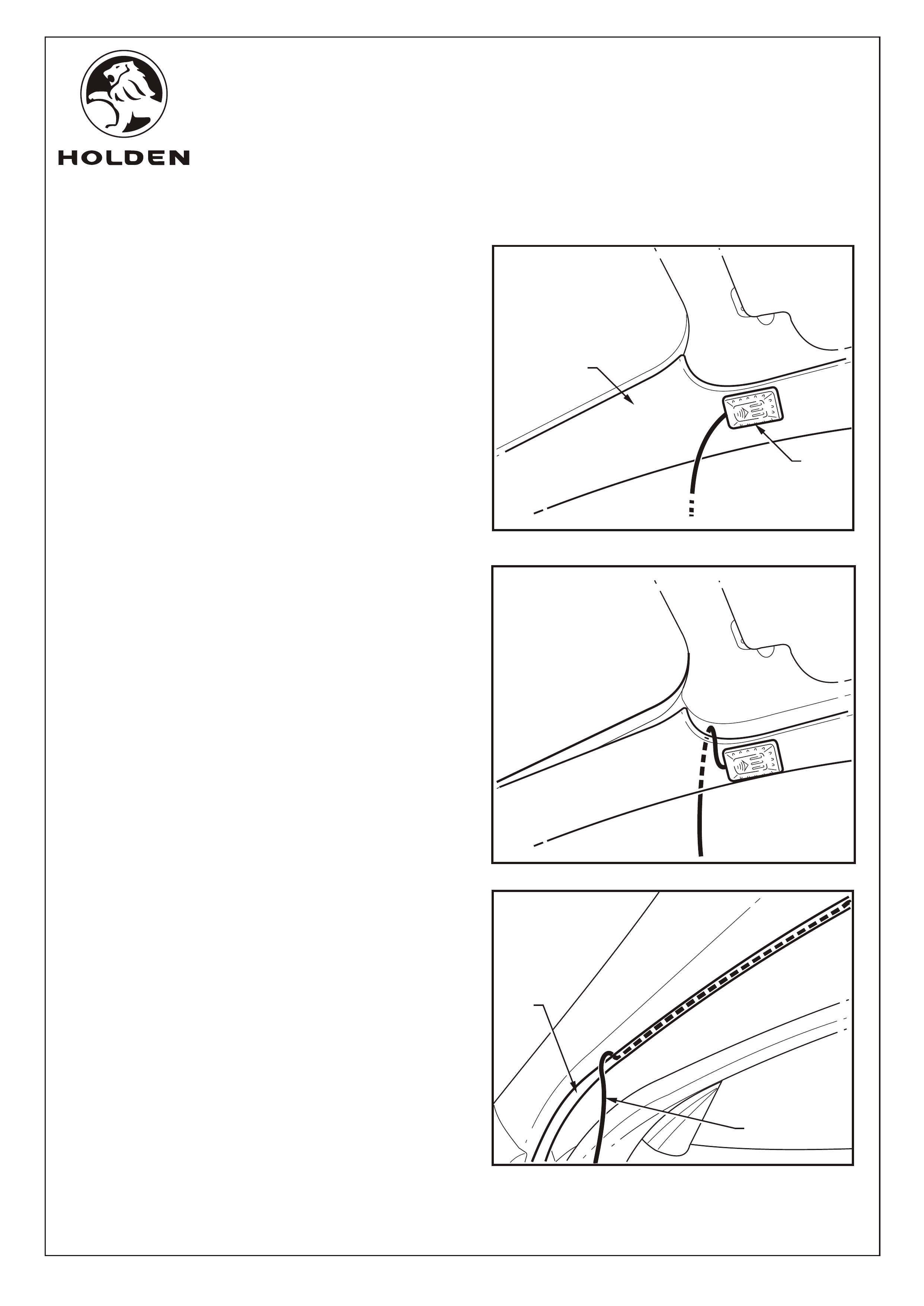
FITTING INSTRUCTIONS: Continued...
Refer to Figure 2 for the following:
5. Remove the passenger side front floor console
extension side trim as follows:
a. Remove the two screws (1) (2 places) attaching the
console extension side trim (2) to the instrument
panel.
6. Release the mobile phone breakout connector (1) from
the body harnesses. Refer to Figure 3.
FIGURE 3
1
FITTING INSTRUCTIONS FOR
VY, VY2 & VZ COMMODORE
BLUETOOTH PHONE KIT
COPYRIGHT
Reproduction in whole or part
prohibited without written approval
FD1208
03SE04
HOLDEN LTD
Division of HOLDEN Ltd ACN 006 893 232
1
2
3
5
6
4
3
4
Page 3 of 8
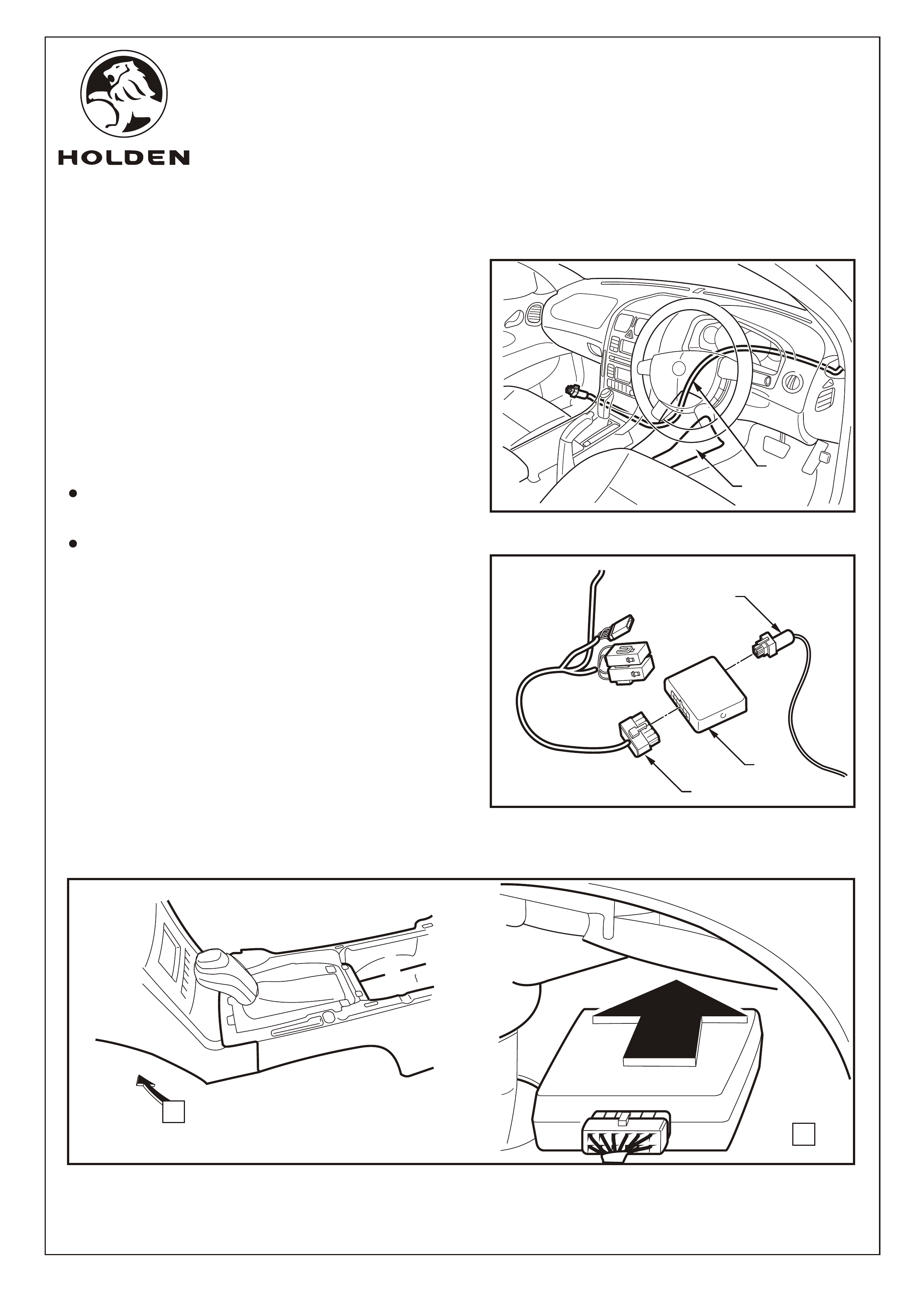
FITTING INSTRUCTIONS: Continued...
7. Raise the armrest; starting at the rear of the console
cover assembly (1), use a trim removing tool (2) to lever
up and release the first 4 console cover tabs to allow
sufficient access. Disconnect the power window switch
harness (4). Refer to Figure 4.
NOTE: If sat nav is fitted remove remote control cradle.
Refer to Figure 5 for the following:
8. Feed the bluetooth harness switch and power window
connectors (1) behind the vehicle body harness (2) and
tuck under the side of the front floor console (3) between
the AC/Heating duct and the vehicle carpet into the rear
switch cavity of the console. Shown with console cover
removed for clarity.
FIGURE 5
FIGURE 4
1
2
3
4
1
3
2
1
2
4
3
5
FITTING INSTRUCTIONS FOR
VY, VY2 & VZ COMMODORE
BLUETOOTH PHONE KIT
COPYRIGHT
Reproduction in whole or part
prohibited without written approval
FD1208
03SE04
HOLDEN LTD
Division of HOLDEN Ltd ACN 006 893 232
1
2
3
5
6
4
3
4
Page 4 of 8
FITTING INSTRUCTIONS: Continued...
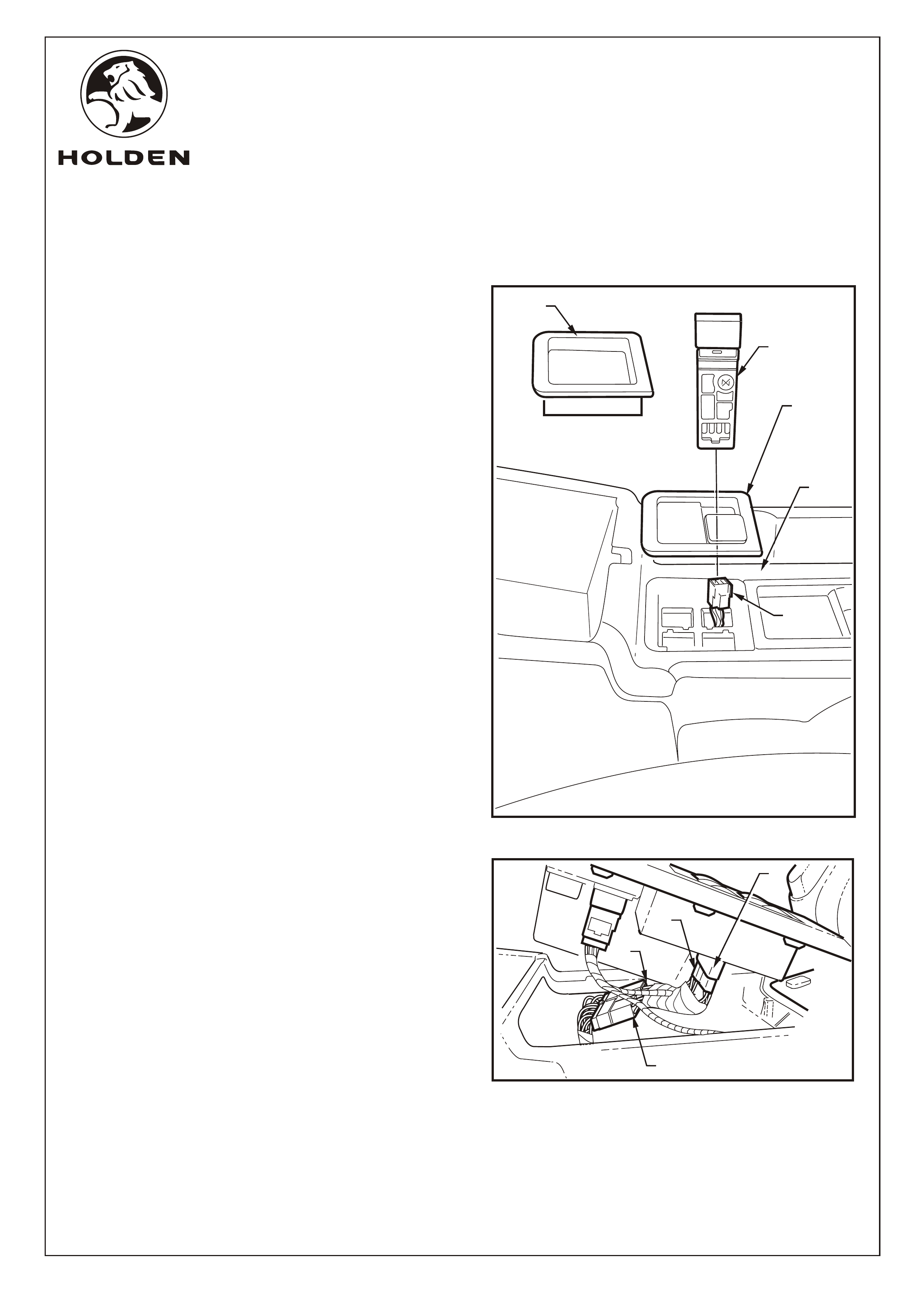
9. Remove the console switch blanking plate or rubber
liner (1) from the rear right corner of the centre console
cover (2). Fit the replacement cover (3) into the
console. Fit the bluetooth switch (4) into the switch
position identified in the bluetooth order form. Connect
the switch to the bluetooth harness connector (5). Fit
the switch blank if required Refer to Figure 6.
Refer to Figure 7 for the following:
10. Connect the bluetooth male (1) and female (2) 13 pin
connectors between the window control harness
connector (3) and connectors of the vehicles window
control switches(4).
FIGURE 6
1
2
3
4
FIGURE 7
1
A-A
A
A
A
A
2
2
(3 PLACES)
3
(2 PLACES)
FIGURE 8
FITTING INSTRUCTIONS FOR
VY, VY2 & VZ COMMODORE
BLUETOOTH PHONE KIT
COPYRIGHT
Reproduction in whole or part
prohibited without written approval
FD1208
03SE04
HOLDEN LTD
Division of HOLDEN Ltd ACN 006 893 232
1
2
3
5
6
4
3
4
FITTING INSTRUCTIONS: Continued...
Refer to Figure 8 for the following:
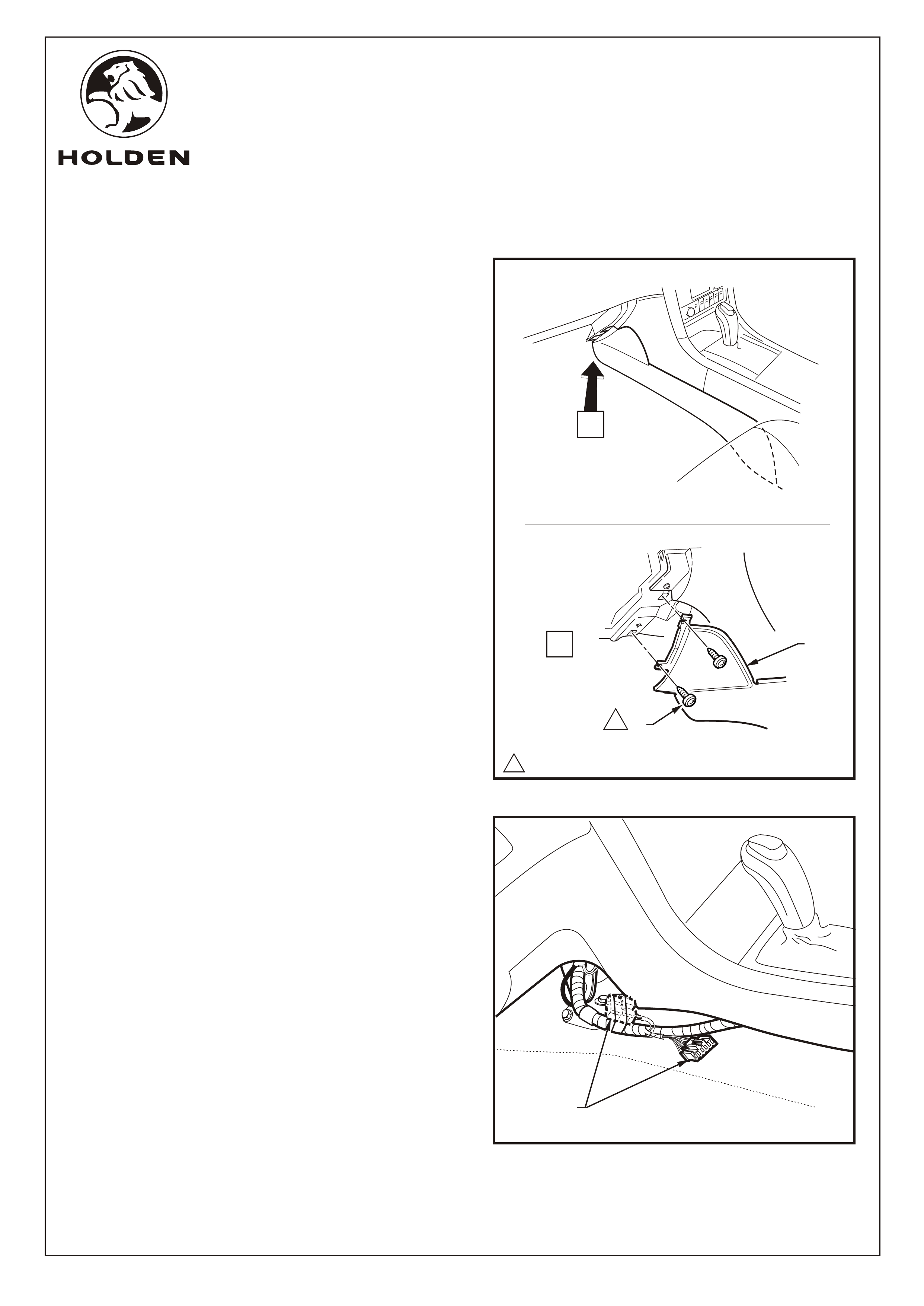
11. Remove the lower instrument trim panel (1) assembly
as follows:
a. Adjust the steering wheel to upper-most position.
b. Grasp the top edge of the lower instrument trim
panel assembly and pull outwards to disengage the
three retaining clips (2).
c. Swing the panel assembly open.
d. Holding each side of the panel assembly pull
rearwards to disengage it from the instrument
panel lower trim panel retainer (3) (2 places).
12. Remove the screws (3 places) retaining the passenger
side dashboard end cover (1). Refer to Figure 9.
FIGURE 9
1
Page 5 of 8
1
2
1
2
FITTING INSTRUCTIONS FOR
VY, VY2 & VZ COMMODORE
BLUETOOTH PHONE KIT
COPYRIGHT
Reproduction in whole or part
prohibited without written approval
FD1208
03SE04
HOLDEN LTD
Division of HOLDEN Ltd ACN 006 893 232
1
2
3
5
6
4
3
4
FITTING INSTRUCTIONS: Continued...
Refer to Figure 10 for the following:
13. Wipe the area where the microphone (1) will attach to
the"A" pillar trim (2) (Not applicable for cloth trim).
14. Peel off the backing tape from the microphone and
push firmly into position for a few second to ensure
permanent adhesion.
Refer to Figure 11 for the following:
15. Pull the "A" pillar trim in to release the two retaining
clips either side of the microphone position (do not
remove trim completely).
16. Pass the microphone wire over the top and behind the
trim. With the microphone wire held taut push the trim
back in position.
Refer to Figure 12 for the following:
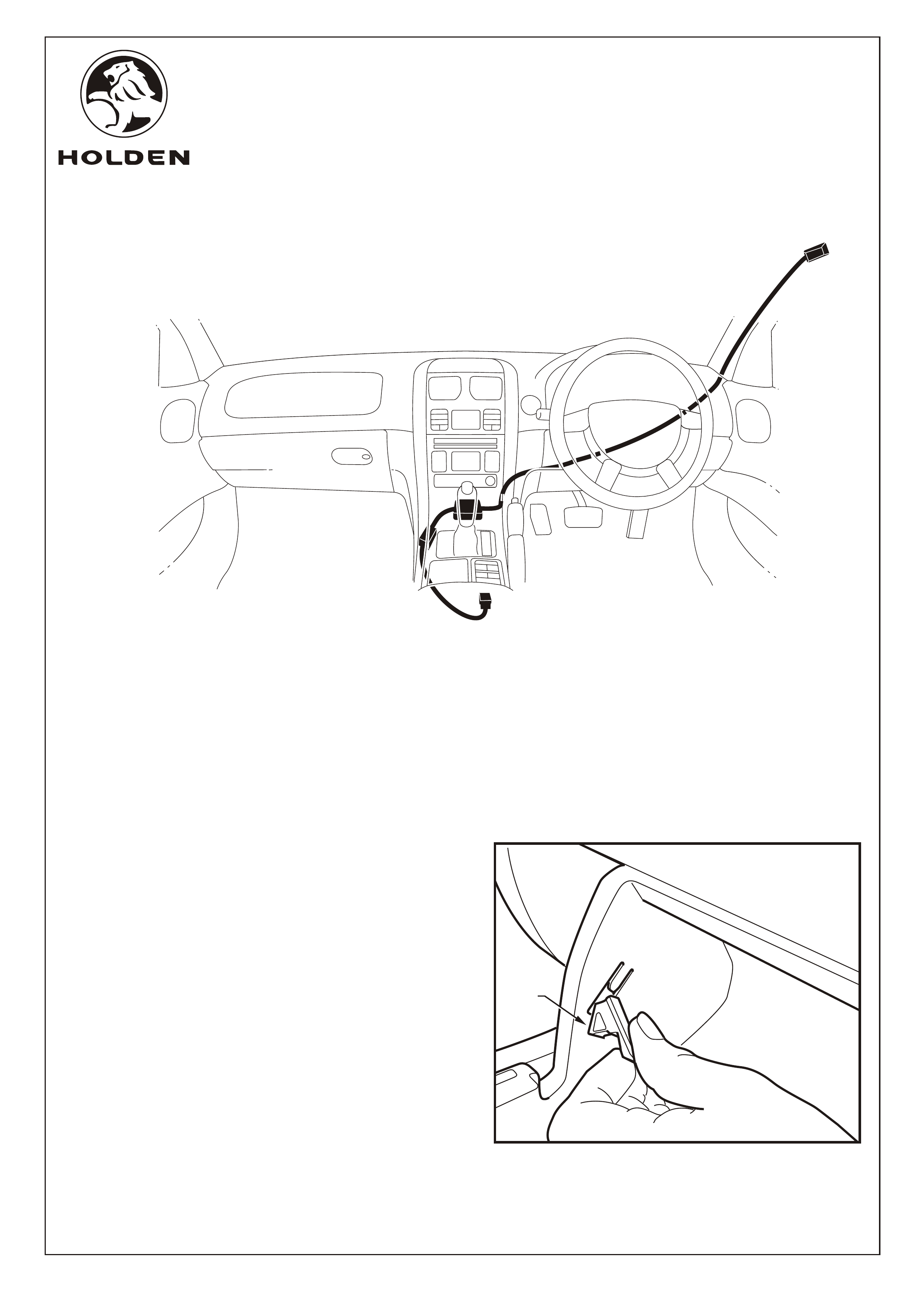
17. Feed the microphone wire (1) down the "A" pillar
between the "A"pillar trim and the rubber door frame
seal (2).
FIGURE 11
FIGURE 10
FIGURE 12
Page 6 of 8
1
2
1
2
3
FITTING INSTRUCTIONS FOR
VY, VY2 & VZ COMMODORE
BLUETOOTH PHONE KIT
COPYRIGHT
Reproduction in whole or part
prohibited without written approval
FD1208
03SE04
HOLDEN LTD
Division of HOLDEN Ltd ACN 006 893 232
1
2
3
5
6
4
3
4
Page 7 of 8
FITTING INSTRUCTIONS: Continue
Refer to Figure 13 for the following:
18. Remove the screws (2 places) retaining the drivers
side lower centre floor console extension trim (1) and
allow to rest on the floor. Refer to step 5.
19. Run the microphone wire (2) through the dashboard
and across to the passenger side of the cavity in front
of the floor mounted centre console.
NOTE:
Ensure wire is routed clear of the steering column
mechanisms.
Ensure wire is retained correctly and can not loop
down into foot well.
Refer to Figure 14 for the following:
20. Connect the microphone connector (1) into the
bluetooth control unit (2).
21. Connect the bluetooth harness (3) into the bluetooth
control unit.
22.
Tuck and push
down the bluetooth control box into the cavity
attaching the Velcro pad to the carpet. Shown with
console cover removed for clarity. Refer to Figure 15.
Connect the bluetooth harness into the vehicle body
mobile harness breakout connector.
FIGURE 14
FIGURE 13
FIGURE 15
VIEW A
A
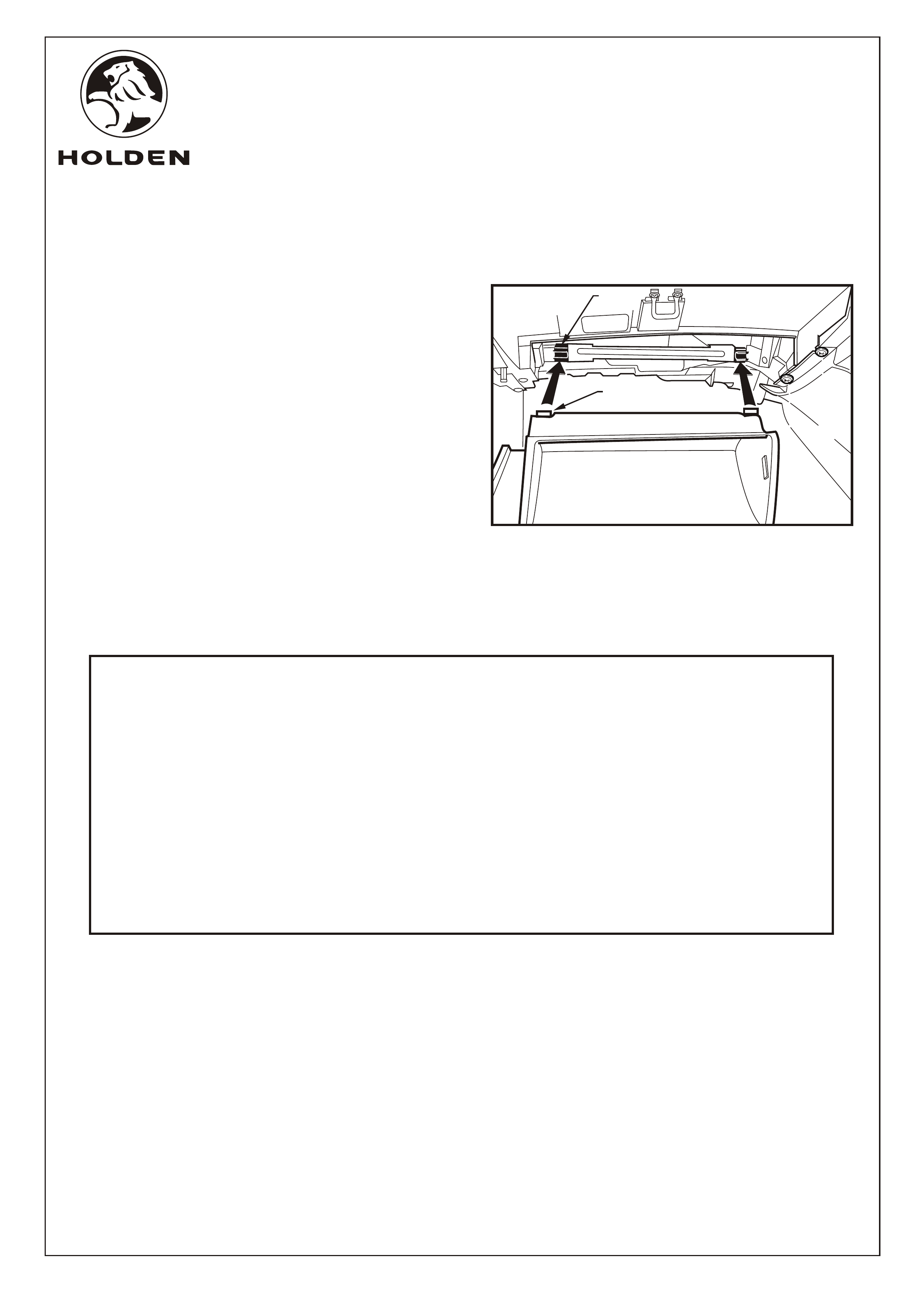
FITTING INSTRUCTIONS: Continued...
23. Apply cable ties to retain the microphone wire where
required.
24. To refit the glovebox, align the pivots (1) (2 places) on
the back of the glovebox with the receiving lugs (2) (2
places) in the glovebox cavity; push home and close
the glovebox. Refer to Figure 16.
25. Refit all remaining parts in reverse order.
26. Check bluetooth switch illuminates with the door
opening.
27. Place the fitting instructions in the glovebox.
FITTING INSTRUCTIONS FOR
VY, VY2 & VZ COMMODORE
BLUETOOTH PHONE KIT
COPYRIGHT
Reproduction in whole or part
prohibited without written approval
FD1208
03SE04
HOLDEN LTD
Division of HOLDEN Ltd ACN 006 893 232
1
2
3
5
6
4
3
4
Page 8 of 8
FIGURE 16
1
2
PARTS LIST
PART No. DESCRIPTION QUANTITY
92176680 BLUETOOTH HANDS FREE PHONE KIT 1
92179549 CONTROL MODULE 1
92179547 MICROPHONE 1
92179548 HARNESS 1
OPERATING SWITCH (SS Black 92172330) (Dark Tempest 92172331) 1
SWITCH BLANKS as supplied
CABLE TIES 5
VELCRO PAD (50mm x 50mm x 3mm) 1
FD1279 OWNERS MANUAL 1
FD1208 FITTING INSTRUCTIONS 1
FD796 PROOF OF WARRANTY CARD 1
NOTE: Bluetooth phone kits are ordered specifically to dealer requirements (see bluetooth phone kit order