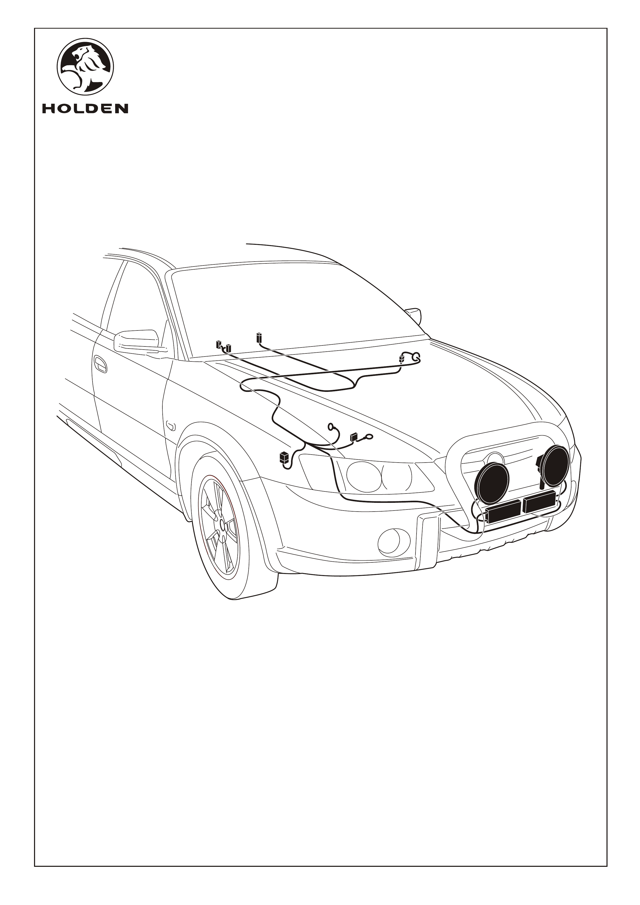
FITTING INSTRUCTIONS FOR
DRIVING LAMPS
FD1232
18NOV04
COPYRIGHT
Reproduction in whole or part
prohibited without written approval
HOLDEN LTD
Division of HOLDEN Ltd ACN 006 893 232
Page 1 of 12
IMPORTANT NOTE:
The driving lamps fitted via these instructions are extremely bright lamps, which can cause discomfort to other road
users if used inappropriately.
NOTE:
The nudge/bull bar (available separately) must be fitted before mounting the driving lamps.
TOOLS REQUIRED:
Phillips Head Screwdriver, Small Flat-bladed Screwdriver, Torx No. 30 Security Bit, Side Cutters, 10mm Socket,
12mm Socket, 10mm Spanner, Trim Removal Tool,
Part No: 92177441 (HALOGEN)
92177442 (HID)
FITTING INSTRUCTIONS FOR
DRIVING LAMPS
FD1232
18NOV04
COPYRIGHT
Reproduction in whole or part
prohibited without written approval
HOLDEN LTD
Division of HOLDEN Ltd ACN 006 893 232
FITTING INSTRUCTIONS:
1. Turn off the ignition switch
2. Disconnect the vehicle battery.
3. Remove the vehicle battery.
4.
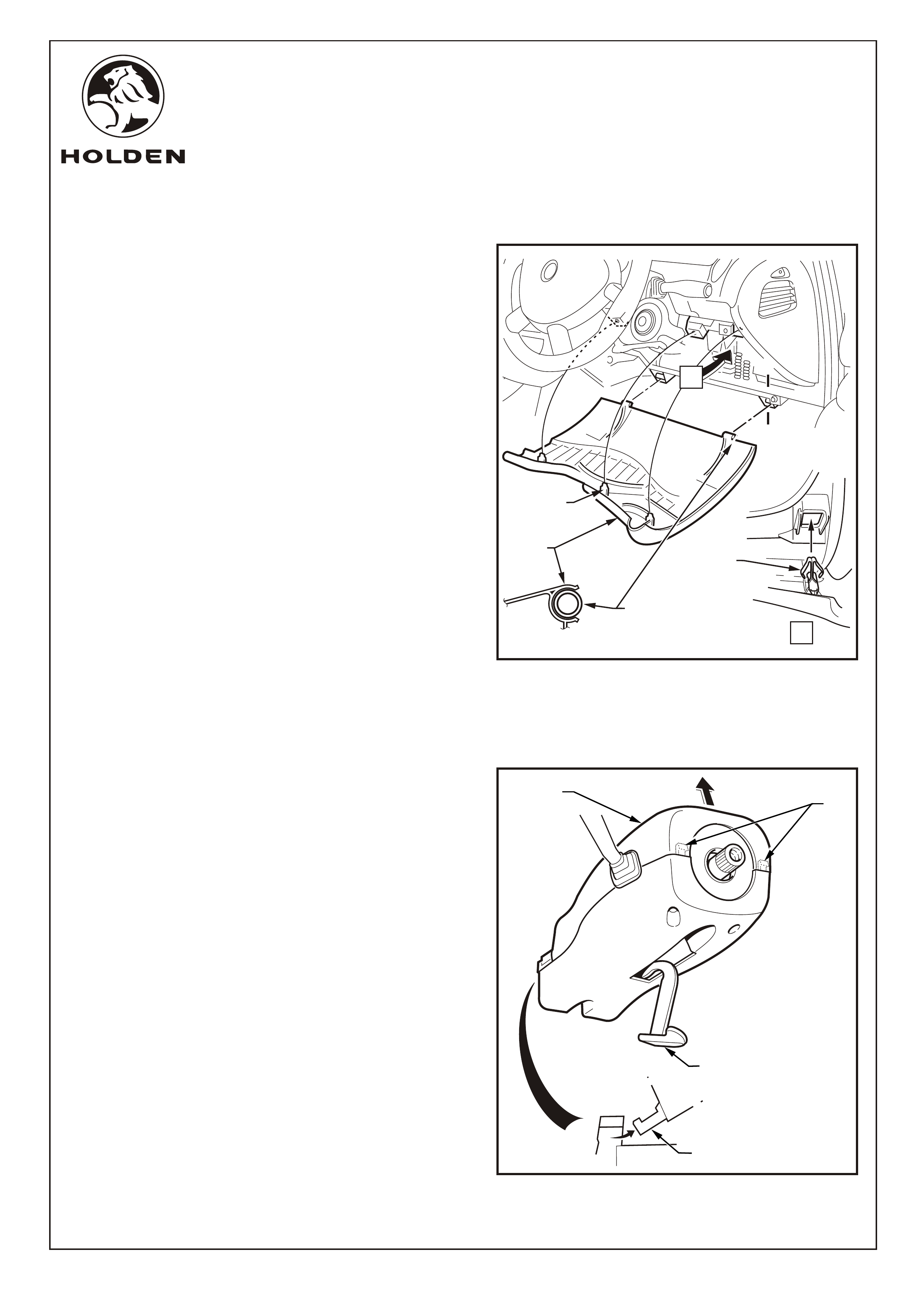
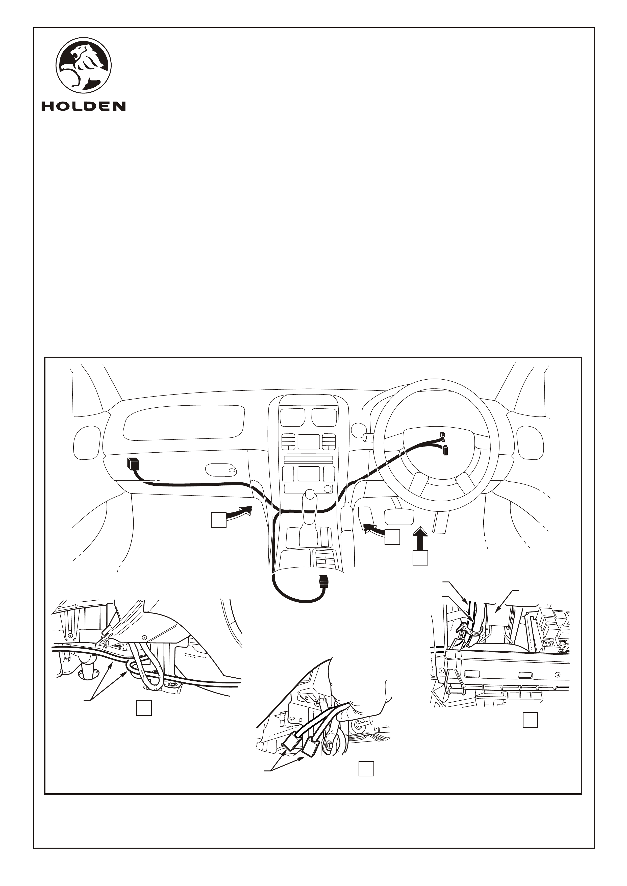
Refer to Figure 1 for the following:
5. Remove the lower instrument panel trim panel (1)
assembly as follows:
a. Adjust the steering wheel to upper-most position.
b. Grasp the upper edge of the lower instrument panel
assembly and pull outwards to disengage the three
retaining clips (2).
c. Swing the panel assembly open.
d. Holding each side of the panel assembly, pull
rearwards to disengage it from the instrument panel
lower trim panel retainer (3) (two places).
Move both front seats to their rear-most position.
Refer to Figure 2 for the following:
6. Remove the upper steering column cover (1) as follows:
a. Release the steering column adjustment lever (2)
and move the column to its lowest position.
NOTE: The steering wheel does not need to be
removed. It is not shown for clarity only.
b. Press the face of the lower cover inwards to
disengage the tabs (3) and lift the steering column
upper cover.
c. Raise the upper cover as high as possible to
disengage the lugs (4) and remove the cover.
1
A-A
A
A
A
A
2
2
3
FIGURE 1
1
2
3
4
FIGURE 2
Page 2 of 12
FITTING INSTRUCTIONS FOR
DRIVING LAMPS
FD1232
18NOV04
COPYRIGHT
Reproduction in whole or part
prohibited without written approval
HOLDEN LTD
Division of HOLDEN Ltd ACN 006 893 232
FITTING INSTRUCTIONS: - continued..
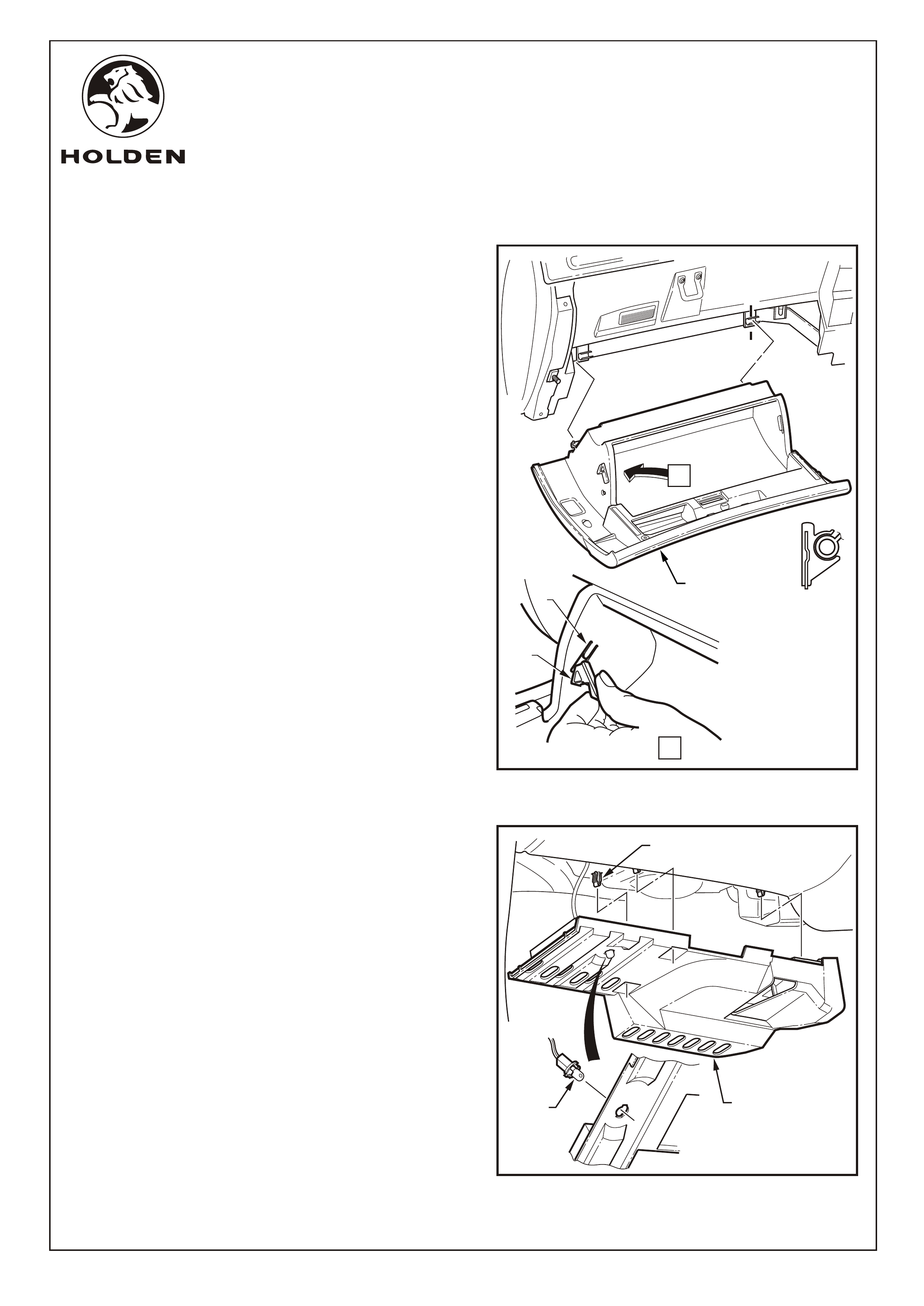
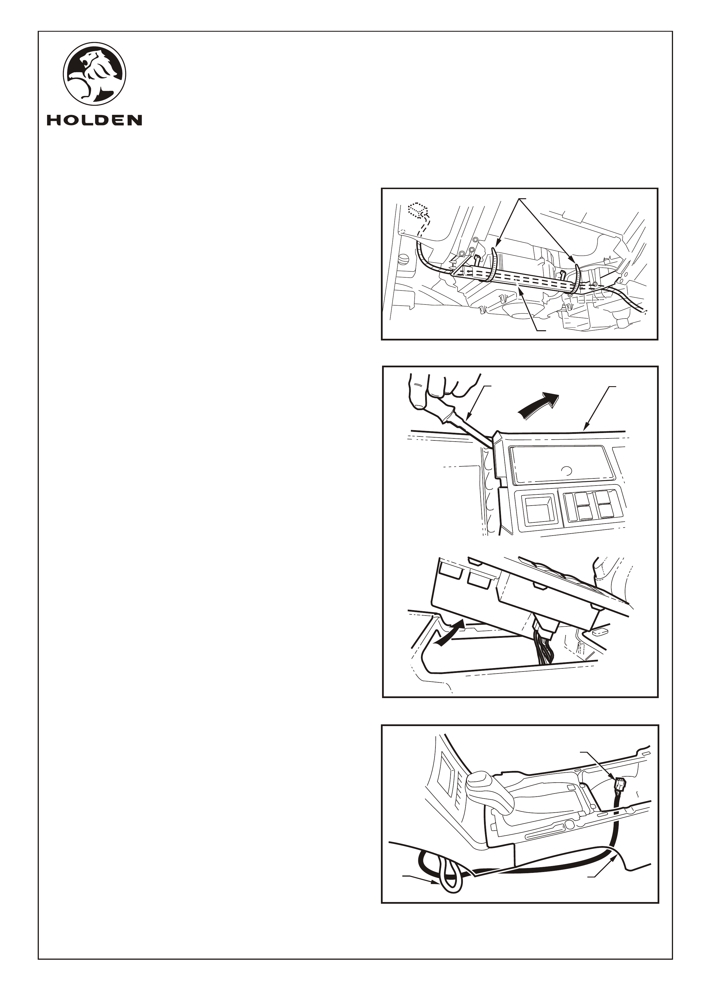
Refer to Figure 3 for the following:
7. Open the glovebox (1) and remove the two travel limiting
lugs (2). This is done by carefully raising the rubber tabs
on the limiting lugs and pulling them rearwards. Once
pulled rearwards, gently pull the rubber tabs towards the
center of the glovebox. To release the glovebox, pull the
glovebox towards the rear of the vehicle.
NOTE: Care must be taken not to break the tongues (3)
off during travel limiting lug removal.
8. Refit travel limiting lugs and place glovebox to one side.
Refer to Figure 4 for the following:
9. Grasp the passenger side hush panel (1) and carefully
pull downward to disengage the retaining clips (2) (3
places).
10. Lower the hush panel slightly and remove the footwell
lamp (3), if fitted.
11. Remove the hush panel.
A-A
A
A
1
FIGURE 3
2
VIEW A
A
31
2
FIGURE 4
3
Page 3 of 12
FITTING INSTRUCTIONS FOR
DRIVING LAMPS
FD1232
18NOV04
COPYRIGHT
Reproduction in whole or part
prohibited without written approval
HOLDEN LTD
Division of HOLDEN Ltd ACN 006 893 232
FIGURE 5
FITTING INSTRUCTIONS: - continued..
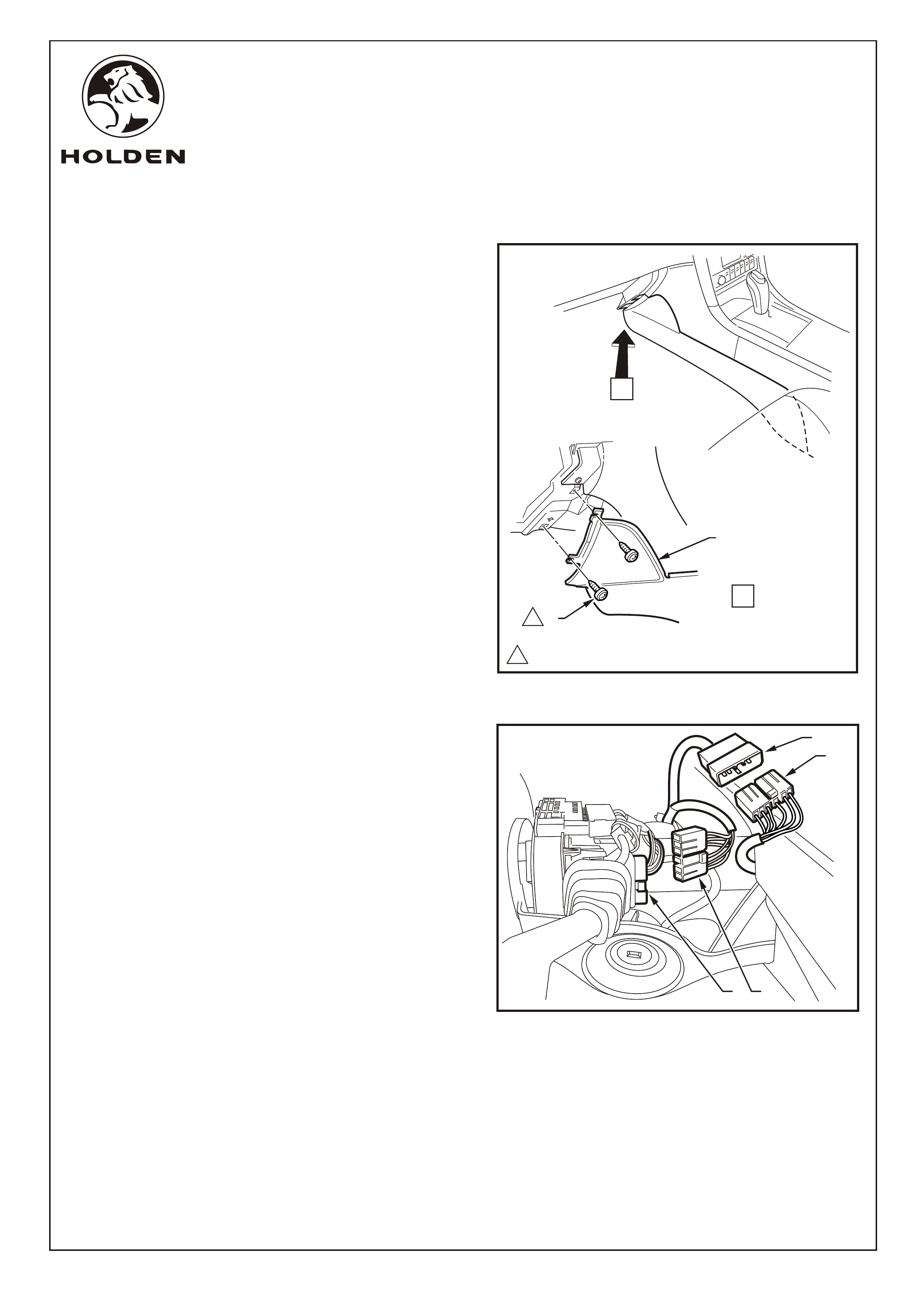
Refer to Figure 5 for the following:
Refer to Figure 6 for the following:
14. Remove the connector (1) from the indicator stalk
connector (2).
15. Connect the connector (3) on the driving lamp harness
to the indicator stalk connector.
16. Connect the existing connector (1) to the connector on
the driving lamp harness (4).
12. Remove the screws (1) (2 places) attaching the front end
of the of the front floor console extension cover (2) on the
passenger side and allow the cover to rotate down to the
floor of the vehicle.
13. Repeat on the driver's side of the vehicle.
A
11.0 - 3.0 Nm
1
2
VIEW A
1
Page 4 of 12
FIGURE 6
4
1
2 3
FITTING INSTRUCTIONS FOR
DRIVING LAMPS
FD1232
18NOV04
COPYRIGHT
Reproduction in whole or part
prohibited without written approval
HOLDEN LTD
Division of HOLDEN Ltd ACN 006 893 232
FITTING INSTRUCTIONS: - continued..
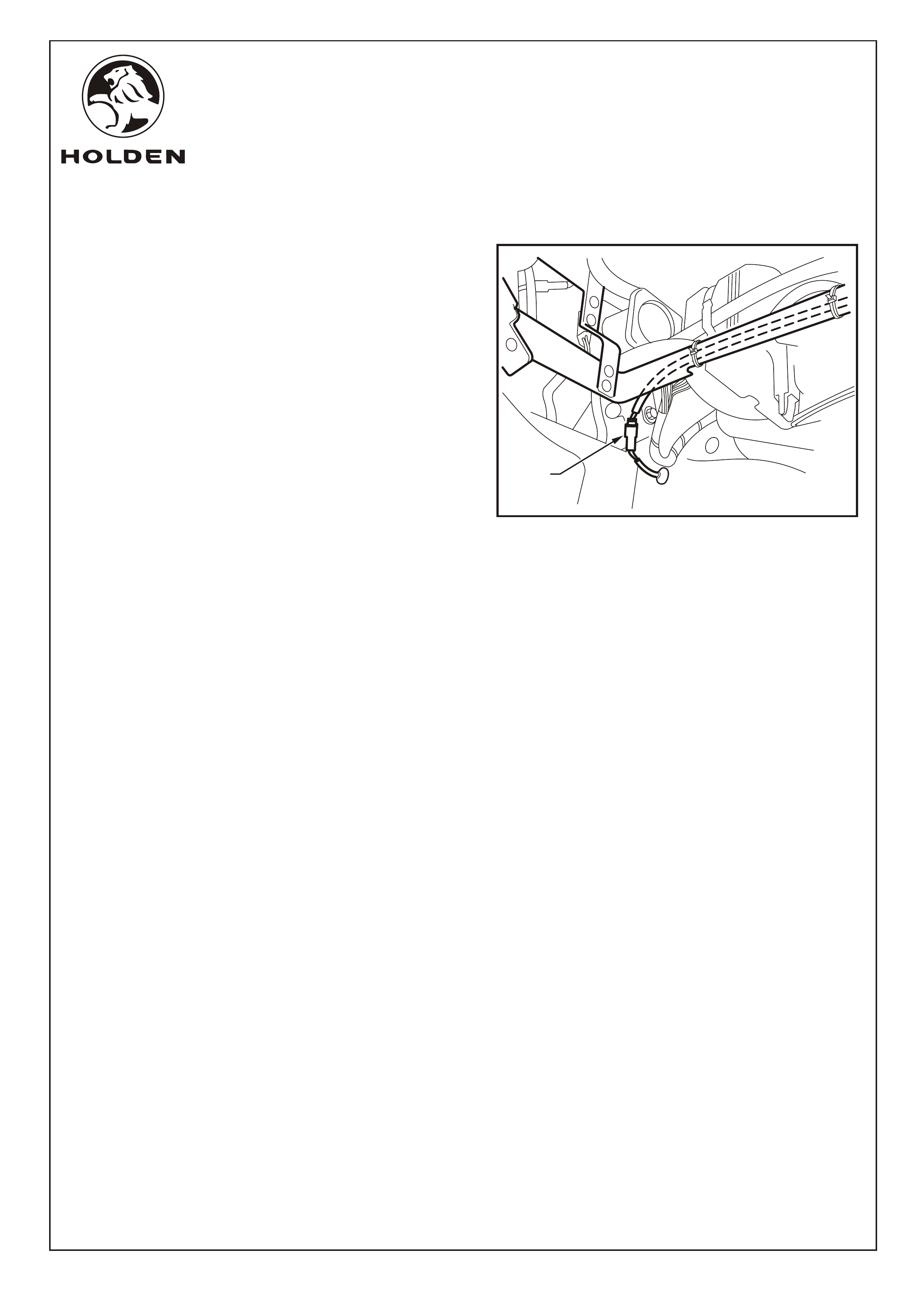
Refer to Figure 7 for the following:
behind
the centre console to the passenger side of the centre
console.
17. Pass the driving lamp harness (1) down the steering
column along the existing vehicle body harness (2).
Attach the wiring harness to the existing vehicle body
harness (3) using cable ties. Refer to View A.
NOTE:Route the wiring harness away from the steering
wheel adjustment mechanism and other moving parts.
18. Pass the driving lamp harness through the cavity
FIGURE 7
VIEW A
VIEW B
VIEW C
B
C
A
2
1
3
Page 5 of 12
1
1
FITTING INSTRUCTIONS FOR
DRIVING LAMPS
FD1232
18NOV04
COPYRIGHT
Reproduction in whole or part
prohibited without written approval
HOLDEN LTD
Division of HOLDEN Ltd ACN 006 893 232
FITTING INSTRUCTIONS: - continued..
Refer to Figure 8 for the following:
NOTE: The AWD wagon has the rear window wash tube
passing through the grommet .
Refer to Figure 9 for the following:
19. Pass the driving lamp harness along the rear glovebox
support (1) member and up towards the grommet hole.
20. Cable tie in two places (2) to prevent movement.
21. Raise the armrest.
22. Starting at the rear of the console cover assembly (1),
use a trim removing tool (2) to lever up and release the
first 4 console cover tabs to allow sufficient access.
NOTE: If sat nav is fitted remove remote control cradle.
Refer to Figure 10 for the following:
23. Feed the driving lamp harness switch connector (1)
behind the vehicle body harness (2) and tuck under the
side of the front floor console (3) between the
AC/Heating duct and the vehicle carpet into the rear
switch cavity of the console. Shown with console cover
removed for clarity.
FIGURE 8
1
2
FIGURE 9
1
2
Page 6 of 12
FIGURE 10
1
3
2
FITTING INSTRUCTIONS FOR
DRIVING LAMPS
FD1232
18NOV04
COPYRIGHT
Reproduction in whole or part
prohibited without written approval
HOLDEN LTD
Division of HOLDEN Ltd ACN 006 893 232
FITTING INSTRUCTIONS: Continued...
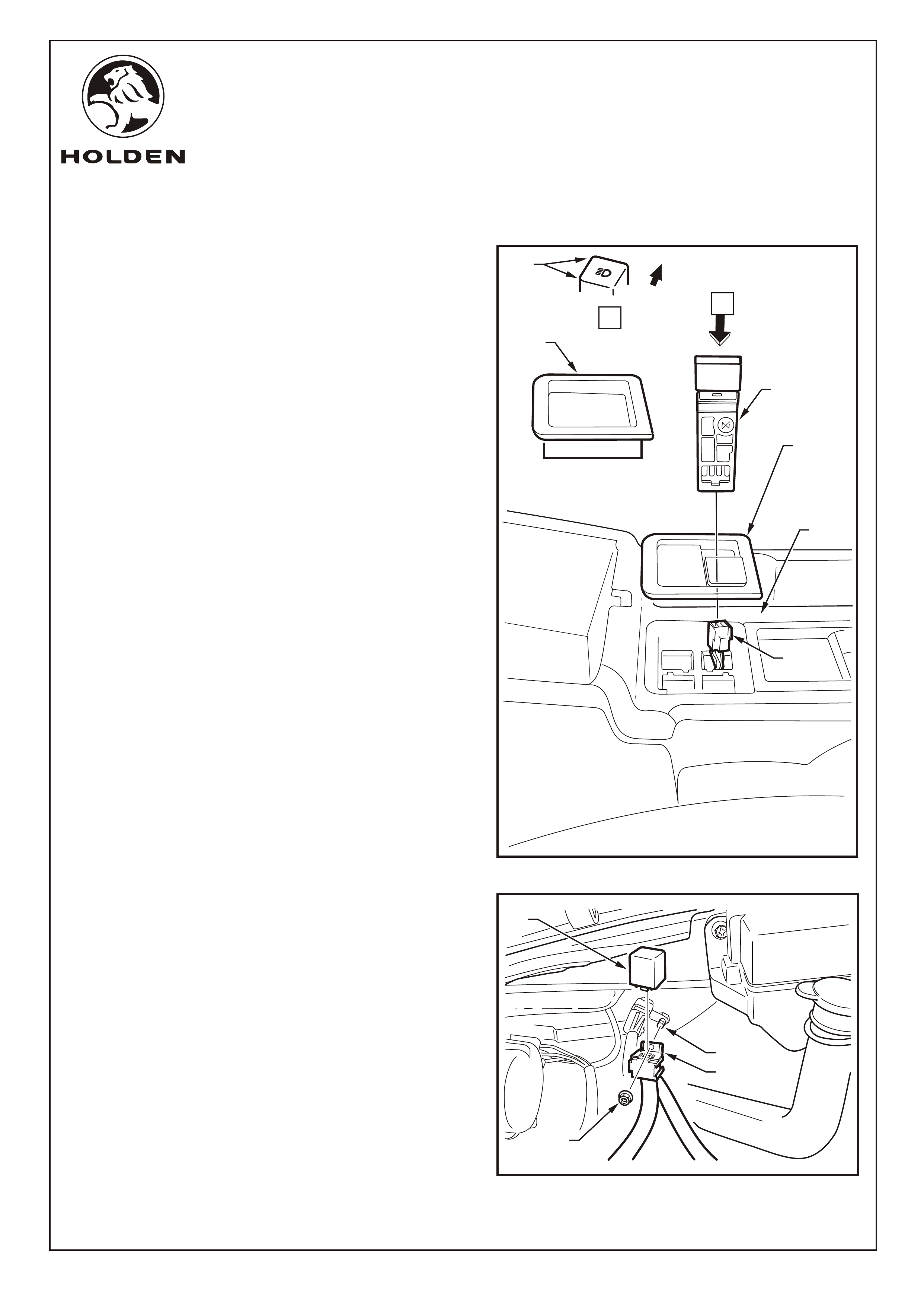
Refer to Figure 11 for the following:
NOTE: The driving lamp switch location and bezel
configuration is customised for each vehicle as
requested on the driving lamp order form.
24. Remove the console switch blanking plate or rubber
liner (1) from the rear right corner of the centre console
cover (2).
25. Fit the driving lamp switch (4) into a vacant switch
position so that the driving lamp symbol is positioned as
shown. Connect the switch to the driving lamp harness
connector (5).
26. Fit the switch blank(s) if required.
27. Fit the replacement cover (3) into the console.
Refer to Figure 12 for the following:
28. Using the existing nut (1), attach the relay socket (2) on
the stud (3) on the inside of the right front quarter panel
using the existing nut.
29. Insert the relay (4) into the relay socket.
1
2
4
3
FIGURE 11
Page 7 of 12
A
VIEW A
5
FIGURE 12
3
2
4
1
FRONT
5
FITTING INSTRUCTIONS FOR
DRIVING LAMPS
FD1232
18NOV04
COPYRIGHT
Reproduction in whole or part
prohibited without written approval
HOLDEN LTD
Division of HOLDEN Ltd ACN 006 893 232
FIGURE 13
FIGURE 14
FITTING INSTRUCTIONS: Continued...
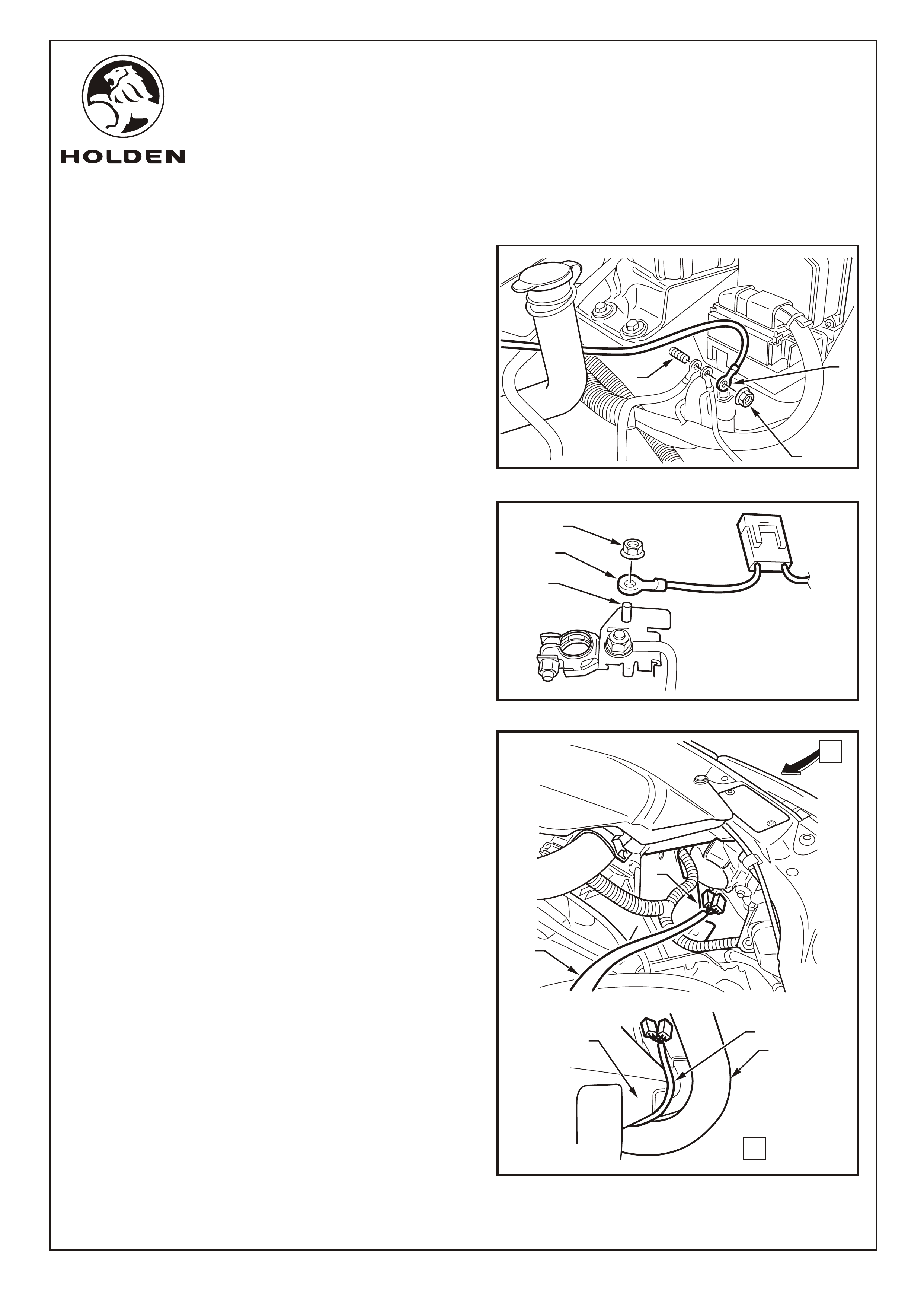
30. Using the existing nut (1), attach the terminal on the
black wire of the driving lamp harness (2) to the body
ground stud (3). Refer to Figure 13.
31. Using the existing nut (1), attach the terminal on the red
wire on the driving lamp harness (2) to the battery
terminal. Refer to Figure 14.
Refer to Figure 15 for the following:
32. From within the engine bay, pass the driving lamp
harness (1) past the front of the radiator (2).
33. From the outside of the vehicle, pass the driving lamp
harness between the front bumper fascia (4) and the
nudge/bull bar (5).
34. Remove the front licence plate from the nudge/bull bar.
3
1
2
1
2
3
Page 8 of 12
FIGURE 15
A
VIEW A
5
1
4
2
1
FITTING INSTRUCTIONS FOR
DRIVING LAMPS
FD1232
18NOV04
COPYRIGHT
Reproduction in whole or part
prohibited without written approval
HOLDEN LTD
Division of HOLDEN Ltd ACN 006 893 232
FITTING INSTRUCTIONS: Continued...
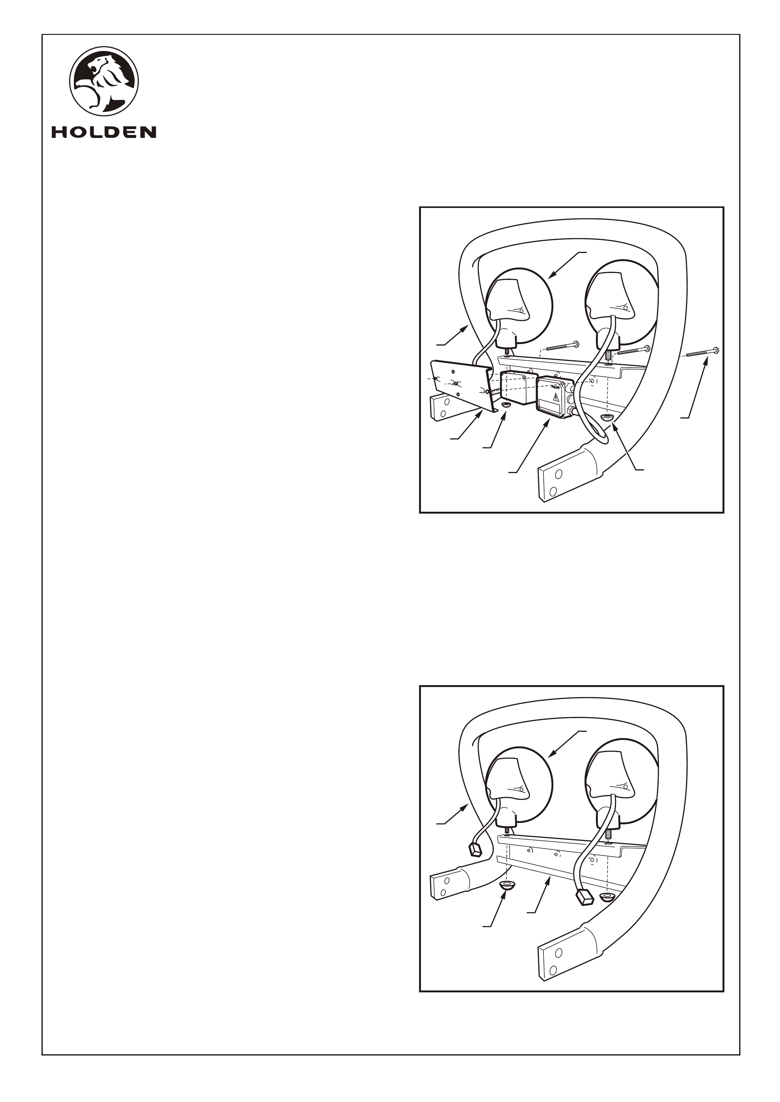
For HID Lamps Only:
Refer to Figure 16 for the following:
35. Attach the driving lamps (1) (2 places) to the nudge/bull
bar (2) using security nuts (3) (1 per lamp).
NOTE: A coded socket is used to fasten the security
nuts.
36. Write the code number of the security socket on the back
page of these fitting instructions and into the front of the
vehicle Owner's Handbook for reference later.
37. Attach the ballast modules (4) (2 places) to the
nudge/bull bar using the attaching plate (6) and security
screws (5) (3 places).
NOTE: Each driving lamp is permanently attached to its
ballast module.
38. Connect the driving lamp harness to the ballast module
(2 places). Ensure that the locking connectors on the
driving lamp harness are correctly oriented on the
ballast modules.
39. Use a cable tie to retain the driving lamp harness behind
the attaching plate.
For Halogen Lamps Only:
Refer to Figure 17 for the following:
40. Attach the driving lamps (1) (2 places) to the nudge/bull
bar (2) using nuts (3) (1 place each lamp).
41. Connect the driving lamp harness to the lamps (2
places).
42. Use cable ties to retain the driving lamp harness at the
rear of the nudge/bull bar horizontal member (4).
For All Lamps:
43. Refit the licence plate.
Page 9 of 12
FIGURE 16
4
3
1
5
2
6
3
FIGURE 17
3
1
2
4
FITTING INSTRUCTIONS FOR
DRIVING LAMPS
FD1232
18NOV04
COPYRIGHT
Reproduction in whole or part
prohibited without written approval
HOLDEN LTD
Division of HOLDEN Ltd ACN 006 893 232
FITTING INSTRUCTIONS: Continued...
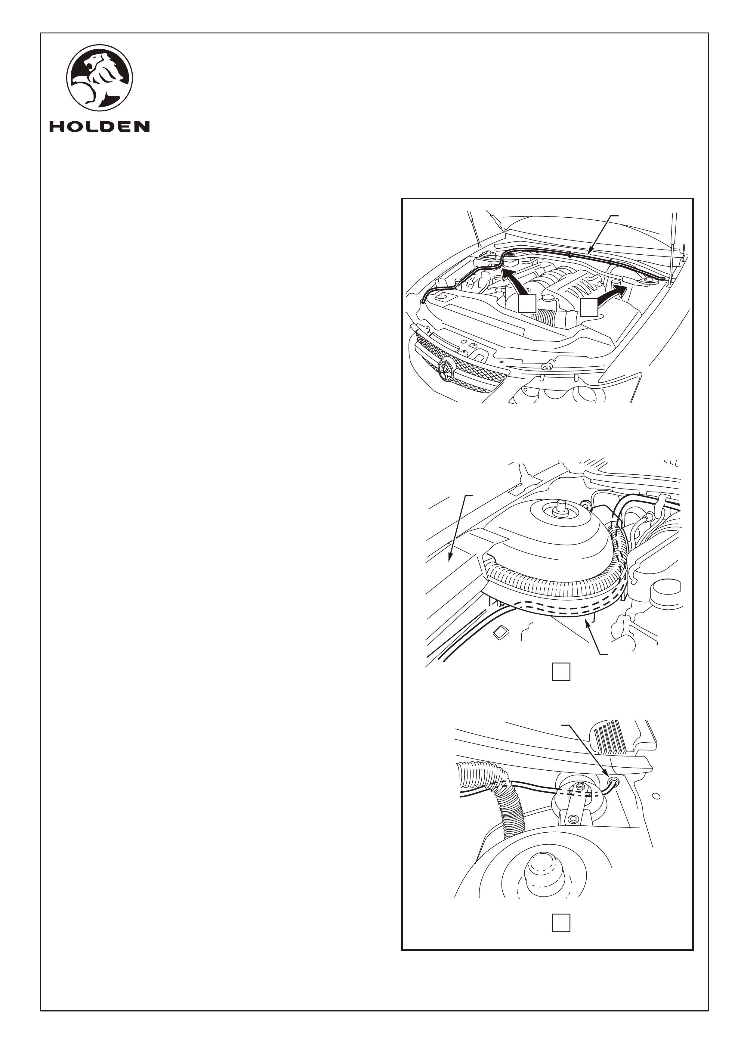
Refer to Figure 18 for the following:
44. Route the driving lamp harness (1) under the fuse box
(2) and around the drivers side strut tower (3). Cable tie
in position.
45. Route the driving lamp harness across the top of the
firewall and retain using the existing cable retainers
46. Use a small screwdriver to remove the existing grommet
from the firewall.
NOTE:
47 Pass the connector on the driving lamp harness through
the hole in the firewall.
48. Fit the grommet (4) on the driving lamp harness into the
hole in the firewall.
The AWD wagon has the rear window wash tube
passing through the grommet .
Page 10 of 12
3
1
AB
VIEW A
VIEW B
2
4
FIGURE 18
FITTING INSTRUCTIONS FOR
DRIVING LAMPS
FD1232
18NOV04
COPYRIGHT
Reproduction in whole or part
prohibited without written approval
HOLDEN LTD
Division of HOLDEN Ltd ACN 006 893 232
Page 11 of 12
FIGURE 19
FITTING INSTRUCTIONS: Continued...
Refer to Figure 19 for the following:
49. Connect the two driving lamp harnesses together (1).
50. Check the operation of the driving lamps.
51. Complete the headlamp aiming procedure as per
Holden service instructions. Refer to MY2003 VY & V2 II
SERIES SERVICE INFORMATION, Section 12B, 2.1
Headlamp and Front Fog Lamp Aiming.
52. Refit all remaining part in reverse order.
53. Place the fitting instructions in the glovebox.
1
FITTING INSTRUCTIONS FOR
DRIVING LAMPS
FD1232
18NOV04
COPYRIGHT
Reproduction in whole or part
prohibited without written approval
HOLDEN LTD
Division of HOLDEN Ltd ACN 006 893 232
PARTS LIST
PART No. DESCRIPTION QUANTITY
92177442 DRIVING LAMP KIT (HID) 1
92171332 DRIVING LAMP (PENCIL BEAM) 1
92178195 DRIVING LAMP (BROAD BEAM) 1
92178198 LENS COVER 2
92178199 SECURITY NUT KIT 1
92178200 HID GLOBE ASM (35W) 2
92171334 WIRING HARNESS 1
92171333 BALLAST MODULE 2
92092444 RELAY 1
SWITCH BLANKS AS SUPPLIED
92179556 DRIVING LAMP SWITCH (SS BLACK)
92179557 DRIVING LAMP SWITCH (DARK TEMPEST)
ATTACHMENT PARTS KIT 1
FD1232 FITTING INSTRUCTIONS 1
FD796 PROOF OF WARRANTY CARD 1
Page 12 of 12
PARTS LIST
PART No. DESCRIPTION QUANTITY
92177441 DRIVING LAMP KIT (HALOGEN) 1
92178196 DRIVING LAMP (PENCIL BEAM) 1
92178197 DRIVING LAMP (BROAD BEAM) 1
92178198 LENS COVER 2
92178201 HALOGEN GLOBE ASM (100W) 2
92171334 WIRING HARNESS 1
92092444 RELAY 1
SWITCH BLANKS AS SUPPLIED
92179556 DRIVING LAMP SWITCH (SS BLACK)
92179557 DRIVING LAMP SWITCH (DARK TEMPEST)
ATTACHMENT PARTS KIT 1
FD1232 FITTING INSTRUCTIONS 1
FD796 PROOF OF WARRANTY CARD 1
SECURITY NUT NUMBER:
(HID LAMPS ONLY)
1
1