FD1235
25AU04
COPYRIGHT
Reproduction in whole or part
prohibited without written approval
HOLDEN LTD
Division of HOLDEN Ltd ACN 006 893 232
FITTING INSTRUCTIONS FOR
VZ AWD CREW CAB & AWD REGULAR CAB
TRANSMISSION COOLER KIT
Page 1 of 6
Part No. 92177284
FITTING INSTRUCTIONS:
IMPORTANT: It is recommended that prior to installing
this kit that the area being worked on be pressure
cleaned to prevent dirt from entering the transmission
lines.
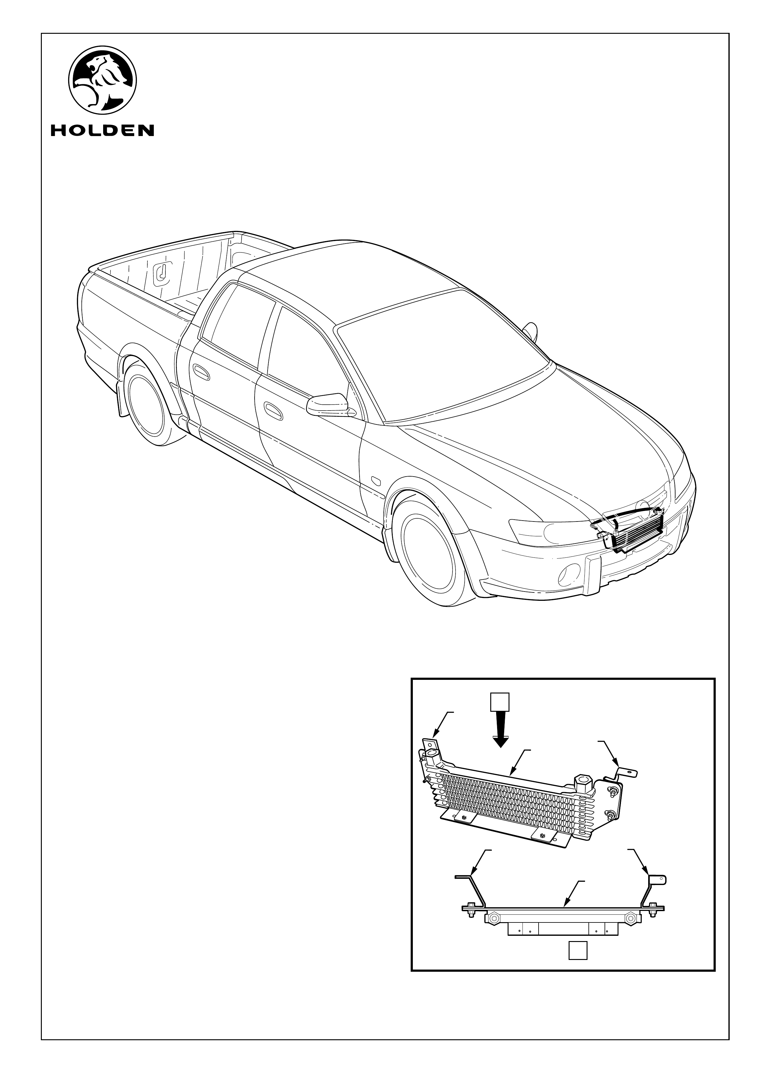
1. Use the nuts and bolts provided to fit the two brackets (1)
onto the transmission cooler (2). Refer to Figure 1.
TOOLS REQUIRED:
Phillips Head Screwdriver, 8mm Socket, 10mm Socket, 450mm Wrench Extension, Wrench, 22mm Open Ended
Spanner, 16mm Open Ended Spanner, Flat Bladed Screwdriver, Hydraulic Snap Connector Release Tool (AU525), Two
Post Hoist (Recommended).
FIGURE 1
A
VIEW A
1
1
11
2
2
FD1235
25AU04
COPYRIGHT
Reproduction in whole or part
prohibited without written approval
HOLDEN LTD
Division of HOLDEN Ltd ACN 006 893 232
FITTING INSTRUCTIONS FOR
VZ AWD CREW CAB & AWD REGULAR CAB
TRANSMISSION COOLER KIT
FIGURE 3
FITTING INSTRUCTIONS: Continued...
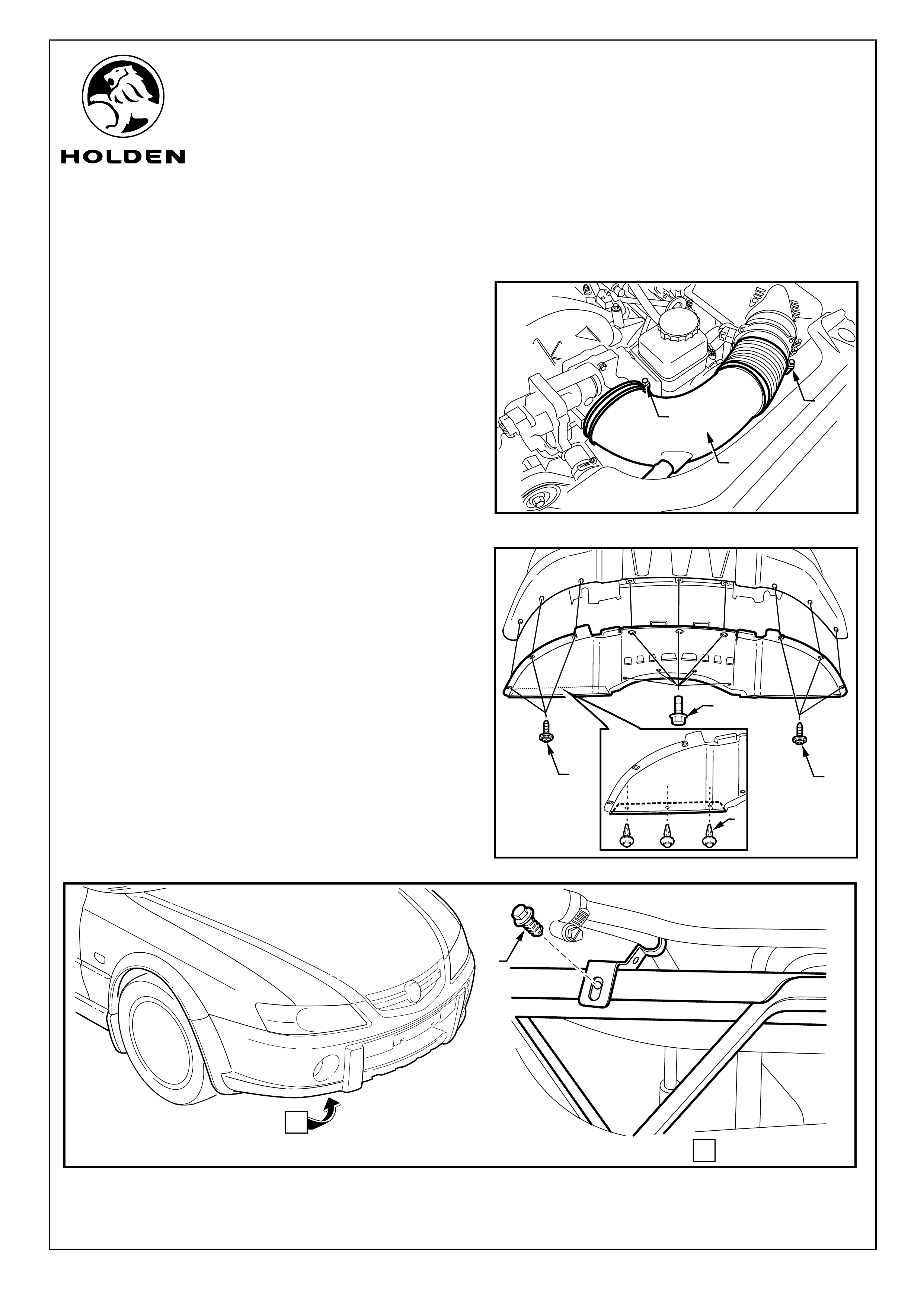
2. Loosen the clamps (1) (2 places) holding the air cleaner
to throttle body duct and move the duct (2) out of the
way. Refer to figure 2.
3. From under the vehicle, remove the bolts (1) (7 places),
screws (2) (6 places) and scrivets (3) (6 places) securing
the front bumper bar lower extension and remove the
front bumper bar lower extension. Refer to Figure 3.
4. Remove the screw from the power steering supply line
support bracket (1). Refer to Figure 4.
Page 2 of 6
FIGURE 4
FIGURE 2
2
1
2
3
1
A
VIEW A
1
1
2
FD1235
25AU04
COPYRIGHT
Reproduction in whole or part
prohibited without written approval
HOLDEN LTD
Division of HOLDEN Ltd ACN 006 893 232
FITTING INSTRUCTIONS FOR
VZ AWD CREW CAB & AWD REGULAR CAB
TRANSMISSION COOLER KIT
Page 3 of 6
FITTING INSTRUCTIONS: Continued...
5. Slide the external cooler assembly over the top of the
lower cross bar and align the right hand bracket of the
external cooler with the power steering pipe support
bracket hole; refit the power steering supply line screw
(1) but do not tighten. Refer to Figure 5.
6. Slide the left hand side cooler support bracket over the
top of front cross member to align the bracket with the
hole in the mounting flange. Fit the self-tapping screw
provided in the kit through the hole in the bracket and
into the mounting flange hole. Refer to Figure 6.
FIGURE 5
1
FIGURE 6
FD1235
25AU04
COPYRIGHT
Reproduction in whole or part
prohibited without written approval
HOLDEN LTD
Division of HOLDEN Ltd ACN 006 893 232
FITTING INSTRUCTIONS FOR
VZ AWD CREW CAB & AWD REGULAR CAB
TRANSMISSION COOLER KIT
Page 4 of 6
FITTING INSTRUCTIONS: Continued...
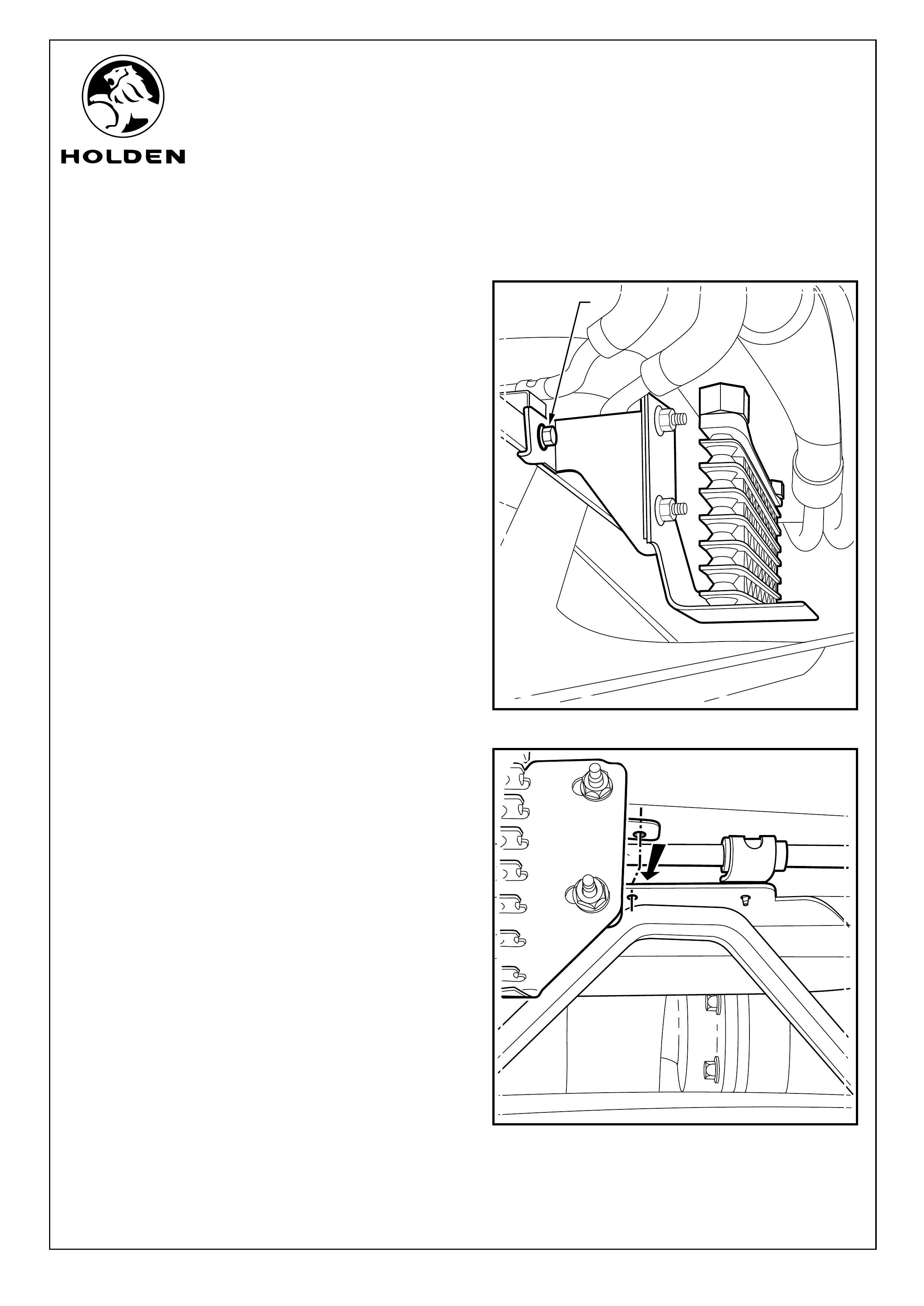
Refer to Figure 7 for the following:
7. Pass a socket with a long extension (1) down between
the radiator and the front of the engine and tighten the
self tapping screw (2) into the cooler mounting bracket
(3).
8. When all screws are fitted, Securely tighten all
fasteners.
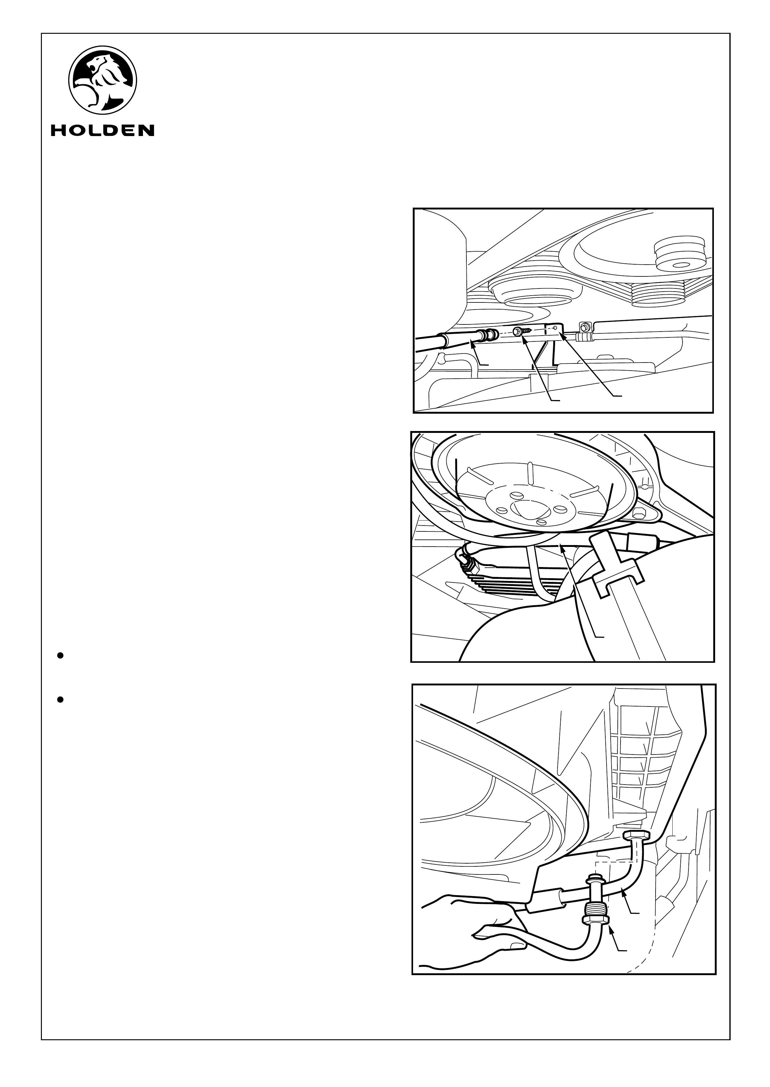
Refer to Figure 8 for the following:
9. Pass the long transmission hose down to the external
cooler assembly so that the end with the flat form will
align with the existing power steering cooler pipe on the
drivers side radiator connector. The other end of the pipe
connects to the passenger side of the external cooler
assembly.
10. Screw the pipe fitting into the external cooler assembly
and tighten.
IMPORTANT: Ensure all connectors are clean prior
to making the connections.
NOTE:
Pre-read steps 11 to 15 so that transmission fluid lose can
be kept to a minimum.
Transmission fluid will be lost in the next steps. Take
action to catch the fluid and discard in an appropriate
manner. Do not reuse the fluid.
Refer to Figure 9 for the following:
11. Use an open-ended spanner to undo the lower
transmission cooling pipe from the radiator (1).
12. Connect the new cooling hose (2) from the external
cooler assembly into the lower radiator and tighten.
FIGURE 7
FIGURE 9
FIGURE 8
1
3
2
1
2
1
FD1235
25AU04
COPYRIGHT
Reproduction in whole or part
prohibited without written approval
HOLDEN LTD
Division of HOLDEN Ltd ACN 006 893 232
FITTING INSTRUCTIONS FOR
VZ AWD CREW CAB & AWD REGULAR CAB
TRANSMISSION COOLER KIT
FITTING INSTRUCTIONS: Continued...
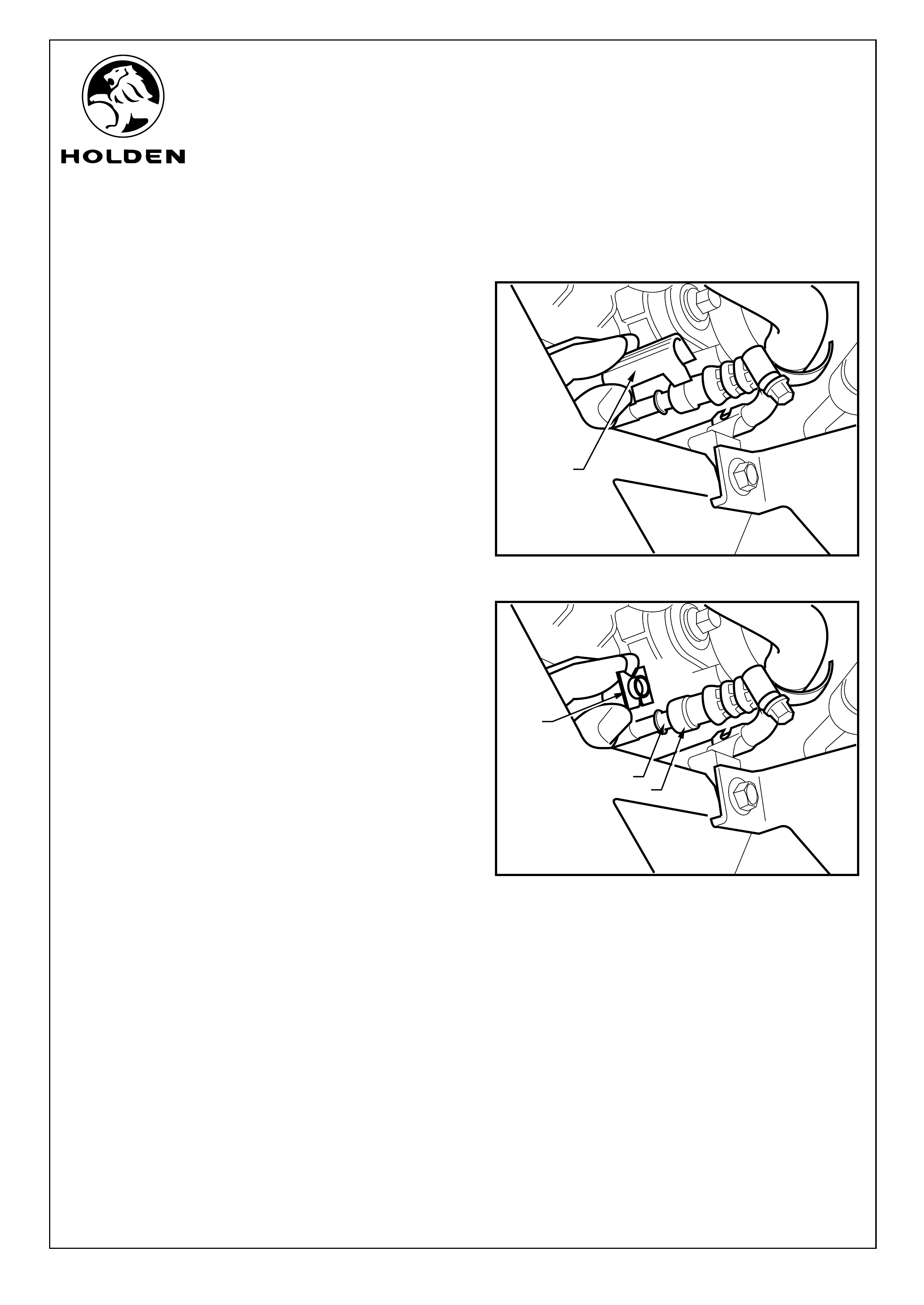
13. Disconnect the other end of the original transmission
line (below engine, drivers side) by removing the white
verification cap (1) that covers the joint. Refer to
Figure 10
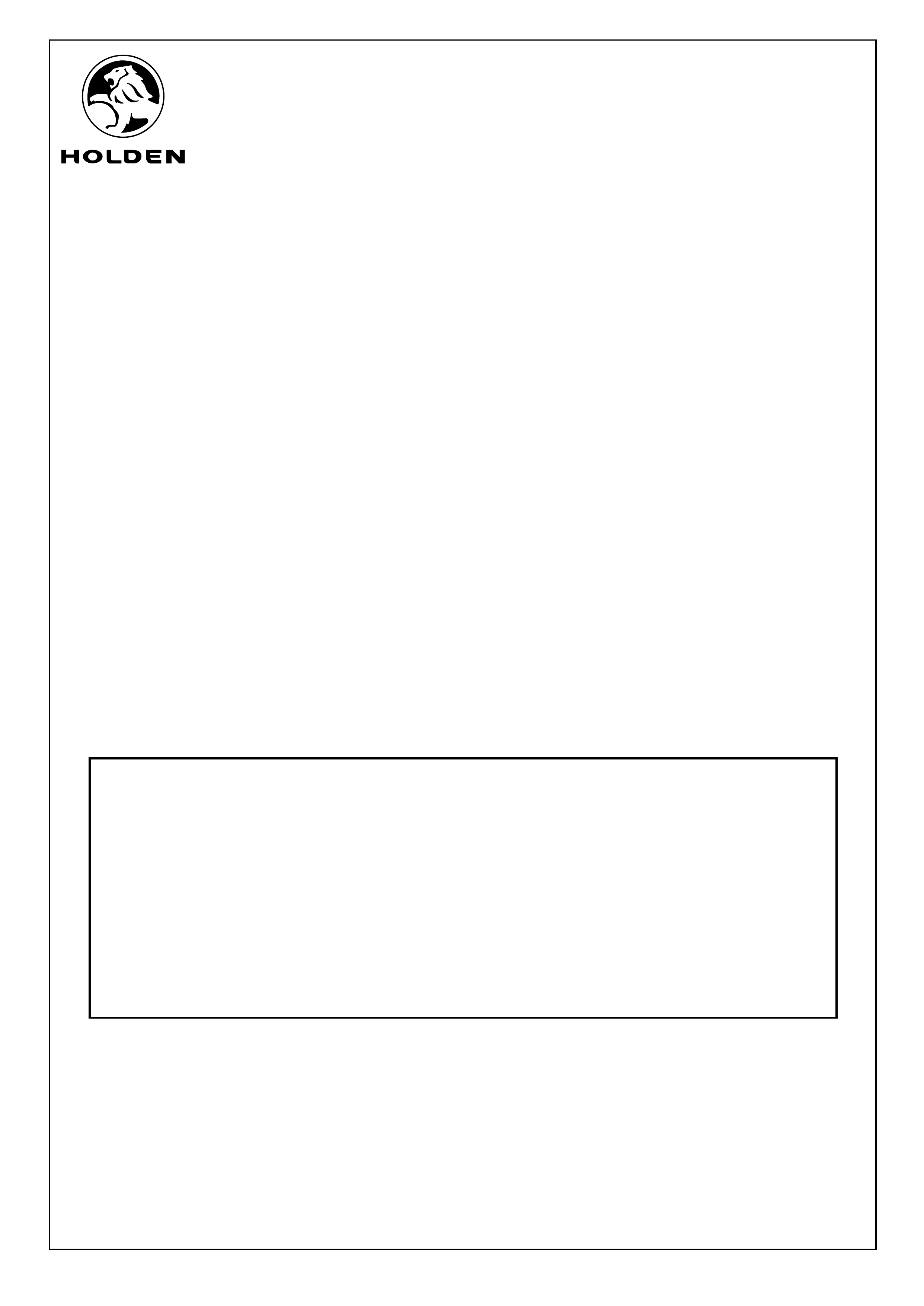
14. Use a hydraulic snap connector release tool (1) to
release the original transmission cooler pipe from the
supply line (2). Place tool over pipe as shown, push into
the fitting (3) and pull the pipe out of the fitting. Use a
clean workshop cloth to catch any transmission fluid.
Refer to Figure 11.
15. Pull the hose off and discard.
16. Connect the new short hose push in connector to the
vehicle transmission pipe and refit locking cover.
NOTE: The verification cap will only fit back in place
when the quick connection is correctly installed.
17. Insert the other end of the new short hose into the
opposite end of the external cooler assembly, screw in
and tighten.
18. Refit the air cleaner to throttle body duct.
FIGURE 10
Page 5 of 6
1
1
2
FIGURE 11
3
FD1235
25AU04
COPYRIGHT
Reproduction in whole or part
prohibited without written approval
HOLDEN LTD
Division of HOLDEN Ltd ACN 006 893 232
FITTING INSTRUCTIONS FOR
VZ AWD CREW CAB & AWD REGULAR CAB
TRANSMISSION COOLER KIT
PARTS LIST
PART NUMBER DESCRIPTION QUANTITY
92177284 TRANSMISSION COOLER KIT 1
92606019 COOLER ASM - TRANS FLUID AUXILIARY 1
92165874 BRACKET - TRANS FLUID AUX CLR (LHS) 1
92165875 BRACKET - TRANS FLUID AUX CLR (RHS) 1
92177285 PIPE ASM - TRANS AUX CLR (RHS) 1
92177286 PIPE ASM - TRANS AUX CLR (LHS) 1
92148958 SMALL PARTS KIT 1
SCREW - SELF TAPPING 1
BOLT - TRANS FLUID AUX CLR 4
NUT - TRANS FLUID AUX CLR 4
FD1235 FITTING INSTRUCTIONS 1
FD796 PROOF OF WARRANTY CARD 1
Page 6 of 6
FITTING INSTRUCTIONS: Continued...
19. Remove the transmission dipstick and add ¼ of a litre of
Dexron® III automatic transmission fluid.
20. Apply the park brake and start the engine, with
accessories turned off. Check all connections for leaks.
21. With the engine idling and the foot brake firmly applied,
move the gear selector through each gear range,
pausing for about 3 seconds in each selected range.
Finally, select the “PARK” position.
22. Let the engine run for 3 minutes with accessories turned
off.
23. Lift the locking lever on the transmission dipstick
indicator, remove dipstick, wipe clean, then reinsert into
the indicator tube. Wait 3 seconds, remove the lever
once again. Check the level of the fluid on each side of
the indicator. The fluid level should be within the “HOT”
indicator section. If necessary add extra fluid until
correct level is achieved.
24. Turn the ignition to the “OFF” position.
25. Refit all remaining parts removed in reverse order.
26. Place fitting instructions in glovebox.