HOLDEN LTD
Division of HOLDEN Ltd ACN 006 893 232
Reproduction in whole or part
prohibited without written approval
COPYRIGHT
FD1237
29JUN04
FITTING INSTRUCTIONS FOR
AWD WAGON TOW BAR TONGUE PACKAGE
Page 1 of 6
Part No. 92171071 (1600 KG)
92171073 (2100 KG)
FIGURE 1
A
TOOLS REQUIRED:
Flat Blade Screwdriver, Drill, Torque Wrench, Ratchet,
10mm and 12mm Sockets, 12.5mm Drill Bit, 1/8” Drill Bit,
Rivet Gun and Rivets.
FITTING INSTRUCTIONS:
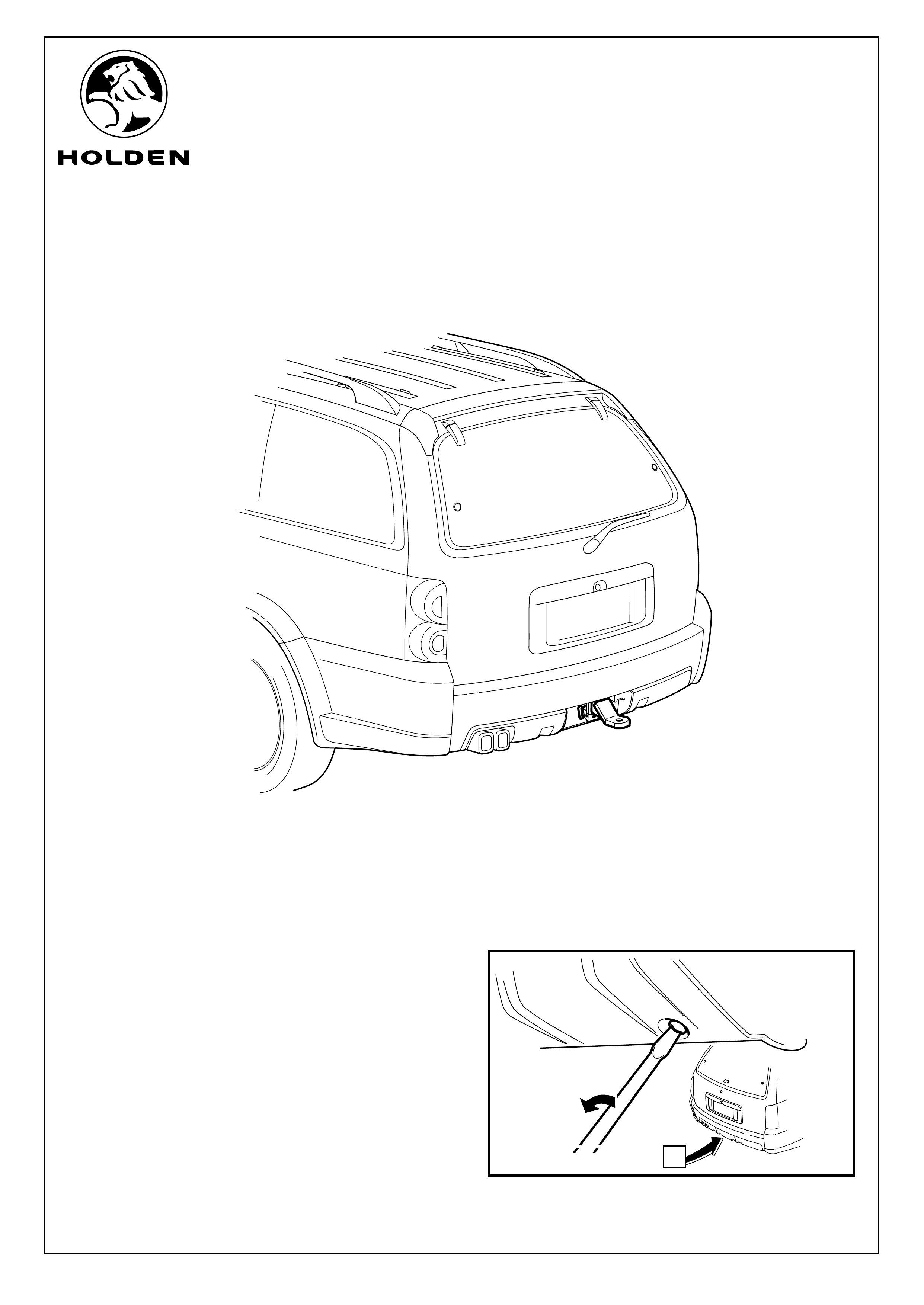
To install towbar tongue:
1. Turn rear fascia tow bar cover fastener, (2 places), a
quarter turn anti-clockwise to unlock, using a flat blade
screwdriver. Refer to Figure 1.
HOLDEN LTD
Division of HOLDEN Ltd ACN 006 893 232
Reproduction in whole or part
prohibited without written approval
COPYRIGHT
FD1237
29JUN04
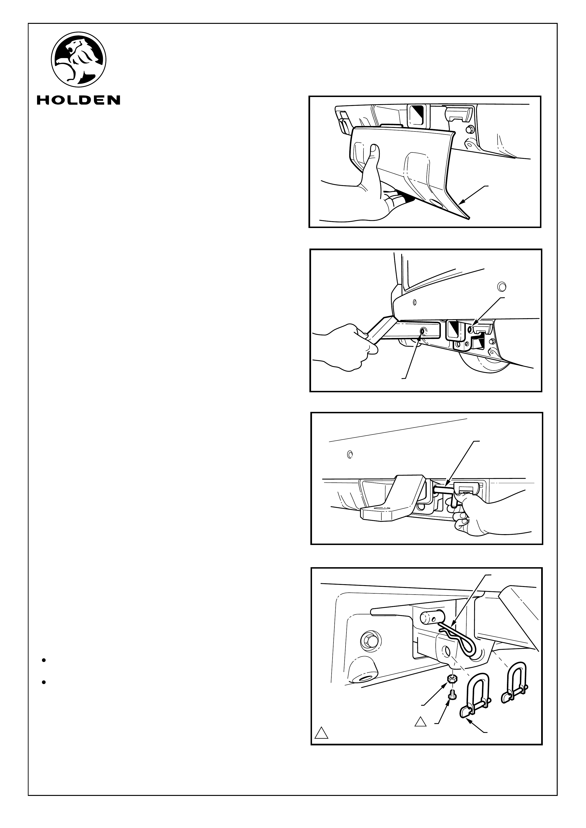
2. Grasp the bottom edge of rear fascia tow bar cover (1)
and pull to remove. Refer to Figure 2.
3. Slide tongue into the tow bar throat so that the tongue
hole (1) and the throat hole (2) are aligned. Refer to
Figure 3.
4. Insert the securing pin (1) through the throat hole and
tongue hole. Refer to Figure 4.
Refer to Figure 5 for the following:
5. Insert the retaining clip (1) into the hole in the securing
pin.
6. Attach the D-shackle (2) (2 places) onto the tow bar as
required.
NOTE:
ŸThe M10 nut (3) and M10x25 anti-rattle bolt (4)
SHOULD BE installed when the towbar is not in use.
ŸThe M10 nut and anti-rattle bolt MUST BE removed
when the towbar is in use.
7. Fit spare wheel well butyl patch heat shield in package
number 92037805 supplied. Refer to fitting instructions
supplied with the package.
Page 2 of 6
1
2
FIGURE 2
FIGURE 3
FIGURE 4
1
FITTING INSTRUCTIONS: - continued
1
FIGURE 5
1
2
3
4
1
40.0 - 50.0 Nm
1
HOLDEN LTD
Division of HOLDEN Ltd ACN 006 893 232
Reproduction in whole or part
prohibited without written approval
COPYRIGHT
FD1237
29JUN04
To upgrade tow bar to 2100kg rating:
10. Remove the scrivets (1) (2 places) from either side of the
towbar opening.
13. Unhook the bumper fascia from the wheelhouse liner.
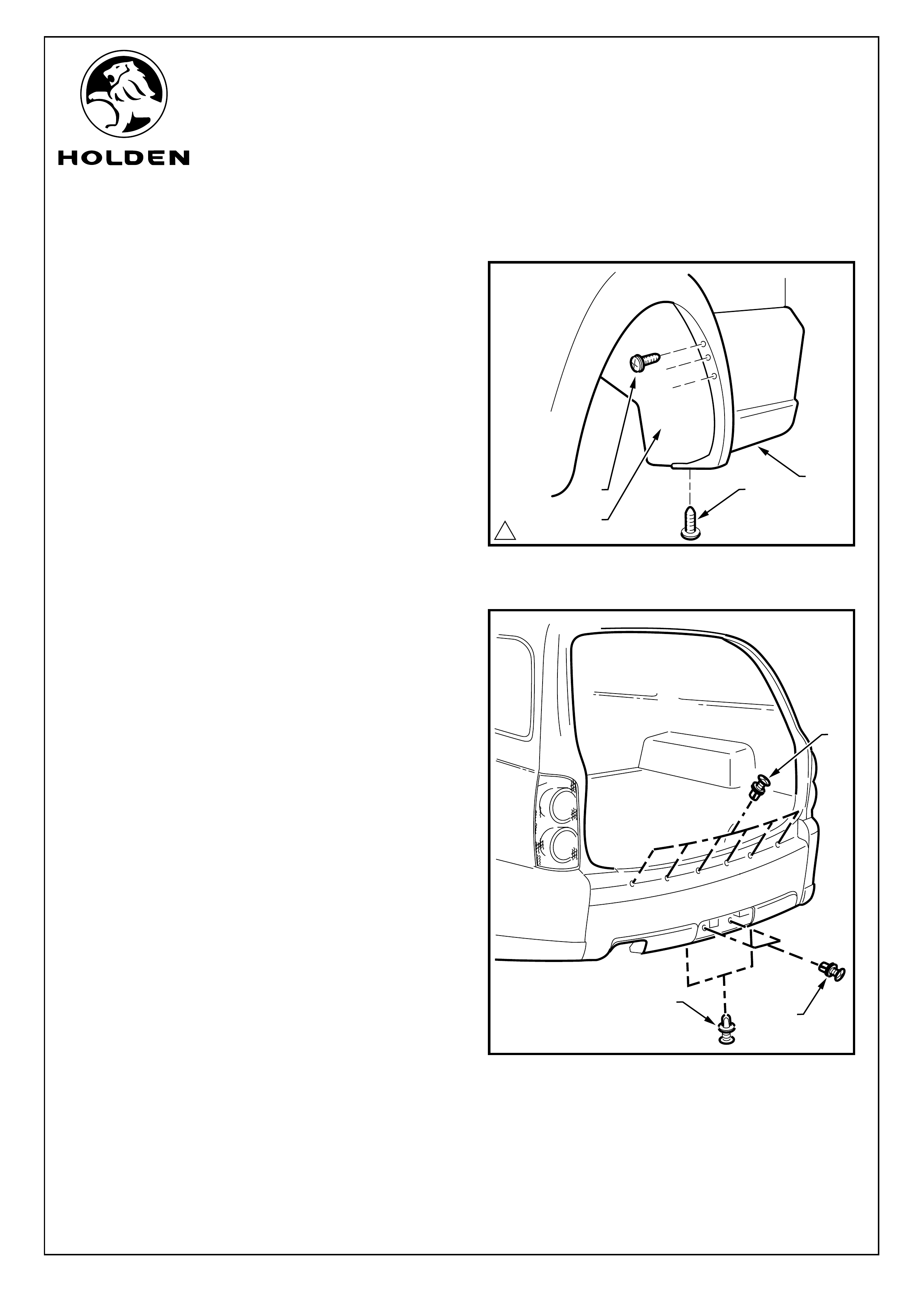
Refer to Figure 6 for the following:
8. Remove the screw (1) (1 place each side of the vehicle)
attaching the rear bumper fascia assembly (2) to the
rear wheelhouse liner (3).
9. Remove the screw (4) (3 places each side of the vehicle)
attaching the rear bumper fascia assembly to the rear
wheelhouse liner (3).
Refer to Figure 7 for the following:
11. Remove the scrivets (2) (2 places) from below the rear
bumper fascia assembly.
12. Remove the scrivets (3) (6 places) from across the
liftgate opening.
FITTING INSTRUCTIONS: - continued
FIGURE 7
Page 3 of 6
FIGURE 6
1
4
2
3
1
2
3
11.0 - 3.0 Nm
HOLDEN LTD
Division of HOLDEN Ltd ACN 006 893 232
Reproduction in whole or part
prohibited without written approval
COPYRIGHT
FD1237
29JUN04
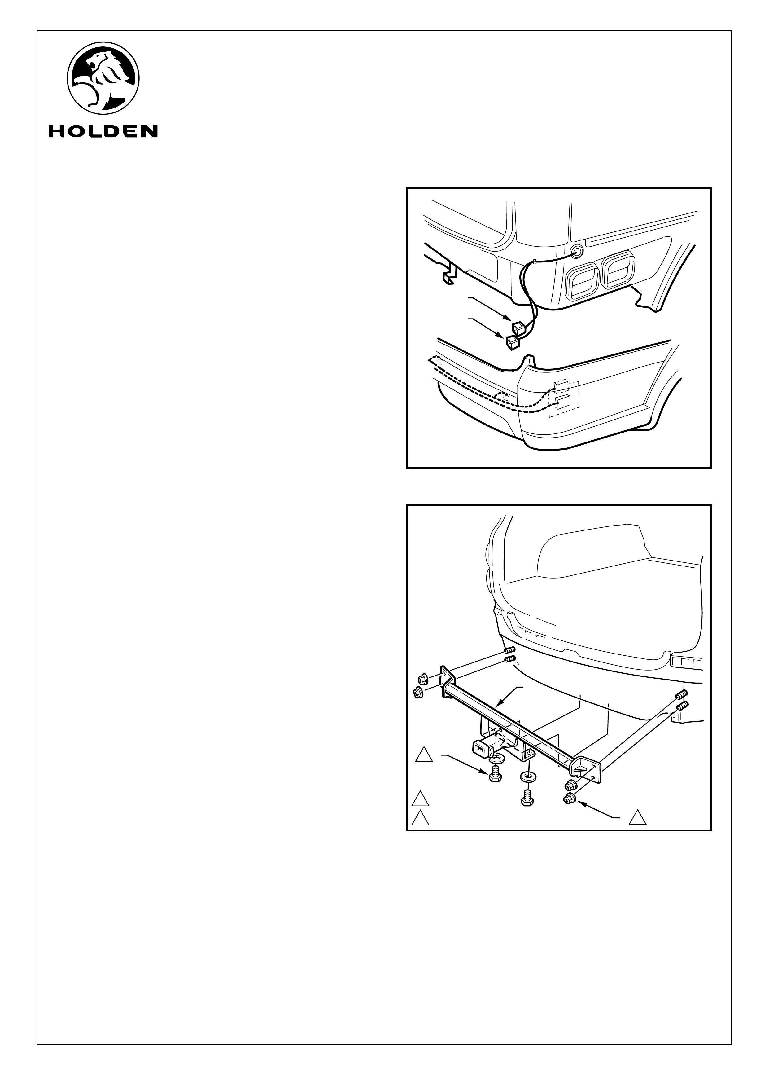
Refer to Figure 8 for the following:
15. With the aid of an assistant, remove the bumper from the
vehicle far enough to access the wiring connectors.
16. Disconnect the towbar wiring harness connector (1).
17. Disconnect the reverse parking aid wiring connector (2).
18. Remove the rear bumper fascia assembly by sliding it
rearward.
Refer to Figure 9 for the following:
19. Remove the bolt (1) (2 places) at the bottom of the
towbar assembly (2).
20. Remove the nuts (3) (2 places each side of the vehicle)
attaching the towbar assembly to the vehicle.
21. Remove the towbar assembly (2).
14. Carefully unclip each side of the bumper fascia
assembly from the guide assembly by grasping and
pulling the upper end of the bumper fascia assembly
until the fascia assembly comes away from the vehicle.
FITTING INSTRUCTIONS: - continued
FIGURE 8
COPYRIGHT
Page 4 of 6
32
1
2
1
FIGURE 9
140.0 - 50.0 Nm
250.0 - 80.0 Nm
1
2
HOLDEN LTD
Division of HOLDEN Ltd ACN 006 893 232
Reproduction in whole or part
prohibited without written approval
COPYRIGHT
FD1237
29JUN04
Page 5 of 6
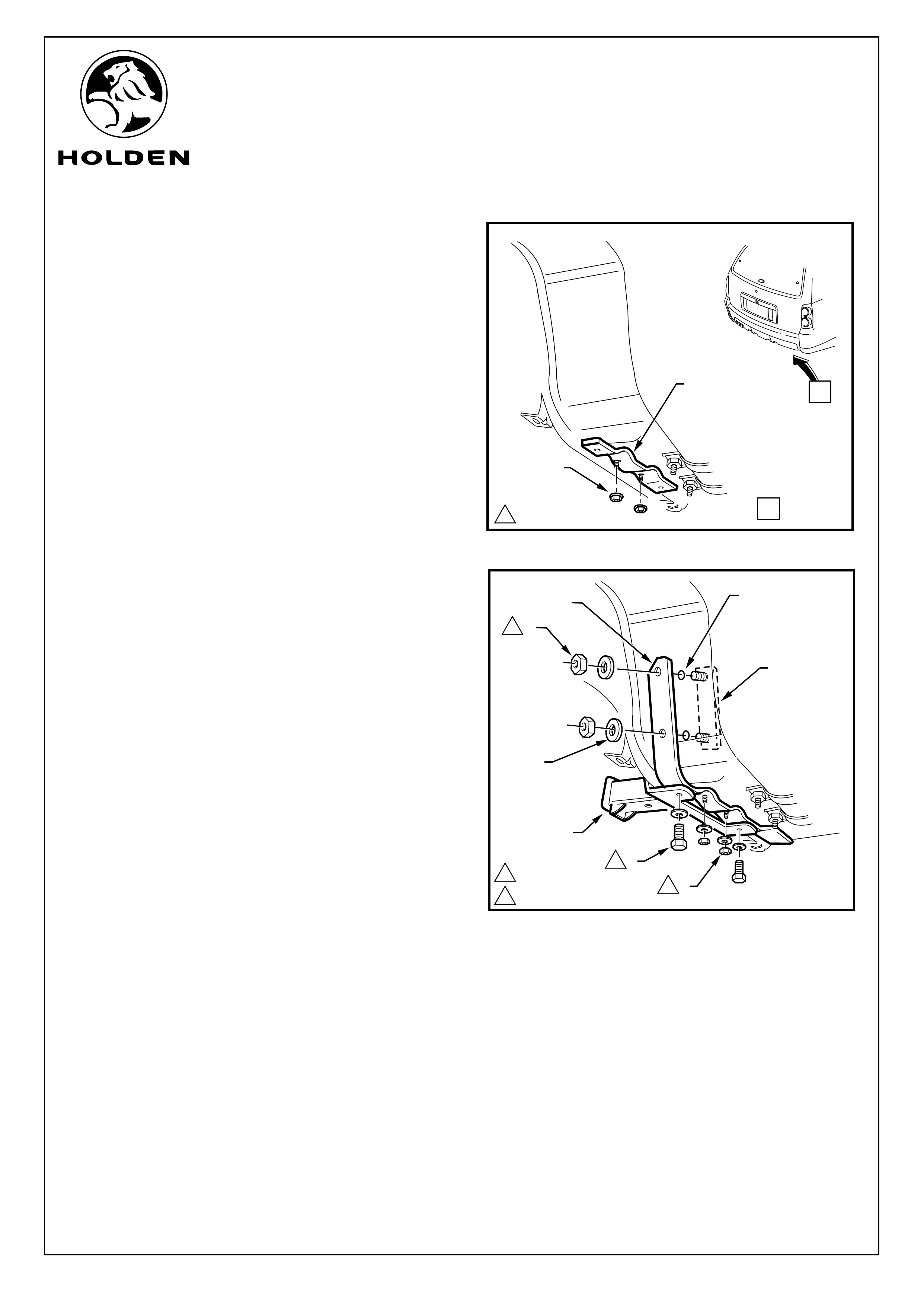
Refer to Figure 10 for the following:
22. Remove M10 flanged nuts (1) (2 places) securing the
existing spare wheel well brace (2) to the underbody
weld studs.
Refer to Figure 11 for the following:
24.
Install M10 nuts and washers (2) (2 places) securing the
new spare whee
o drill two 12.5 dia. holes
(5) in each side through the spare wheel well.
31. Apply silicone or butyl sealer to holes for water sealing &
corrosion protection purposes, (4 places).
32. Remove the backing tape from the two adhesive backed
stud plates (6). Install the
from the inside of the spare wheel well, through holes in
wheel well and spare wheel well brace assembly.
33. From the underside of the vehicle, attach flat washers
(7) and M12 nuts (8) to the studs on the stud plates, (4
places), and tighten to specified torque.
34. Drill out rivets holding existing ADR Load Specification
Plate onto tow bar using 1/8” drill bit and replace plate
with new 2100kg ADR load specification plate supplied.
Rivet the new plate through existing holes to attach.
23. Remove the spare wheel well brace.
Install the new extended spare wheel well brace (1).
25.
l well brace to the wheel well underbody
weld studs and tighten to the specified torque.
26. Reinstall the towbar assembly (3).
27. Install M10 bolts and washers (4) (2 places) securing the
towbar assembly to the new spare wheel brace and
tighten to the specified torque.
28. Reinstall the nuts (3) (2 places each side of the vehicle)
attaching the towbar assembly to the vehicle and tighten
to the specified torque. Refer to Figure 9.
29. Open the tailgate and remove the rear floor and spare
wheel.
30. From the underside of the vehicle, use the new spare
wheel well brace as a template t
CAUTION: Spare wheel must be removed before
performing drilling operations.
adhesive backed stud plates
35. Reinstall the spare wheel and rear floor.
36. Reinstall the rear bumper fascia assembly.
FITTING INSTRUCTIONS: - continued
VIEW A
140.0 - 50.0 Nm
2
FIGURE 10
A
1
FIGURE 11
275.0 - 85.0 Nm
7
6
5
14
3
140.0 - 50.0 Nm
28
12
1
HOLDEN LTD
Division of HOLDEN Ltd ACN 006 893 232
Reproduction in whole or part
prohibited without written approval
COPYRIGHT
FD1237
29JUN04
AWD WAGON TOW BAR TONGUE PACKAGE (1600KG)
PARTS LIST
PART NUMBER DESCRIPTION QUANTITY
92171071 TOWBAR TONGUE PACKAGE - AWD 1600KG 1
- TOWBAR TONGUE 1
92077203 "D" SHACKLE - TOW BAR 2
- PIN & CLIP - TOW BAR 1
- BOLT - ANTI RATTLE. M10X25 1
- NUT - M10 1
92143923 - HEAT SHIELD PACKAGE - SPARE WHEEL WELL 1
FD1237 FITTING INSTRUCTIONS 1
FD796 PROOF OF WARRANTY CARD 1
Page 6 of 6
AWD WAGON TOW BAR TONGUE PACKAGE (2100KG)
PART NUMBER DESCRIPTION QUANTITY
92171073 TOWBAR TONGUE PACKAGE - AWD 2100KG 1
92171071 TOWBAR TONGUE PACKAGE - AWD (CONTENTS AS PER ABOVE) 1
- ADR LOAD SPECIFICATION PLATE (2100KG) 1
- ADR COMPLIANCE LABEL (2100KG) 1
92054275 BRACE ASSEMBLY - TOW BAR 1
92143965 SMALL PARTS KIT 1
- BOLT - M10X25 2
- NUT - M10 2
- WASHER - M10 BRIGHT 4
- STUD PLATE - 2100KG 2
- NUT - M12 4
- WASHER - M12 BRIGHT 4
- RIVET - 1/8” 2
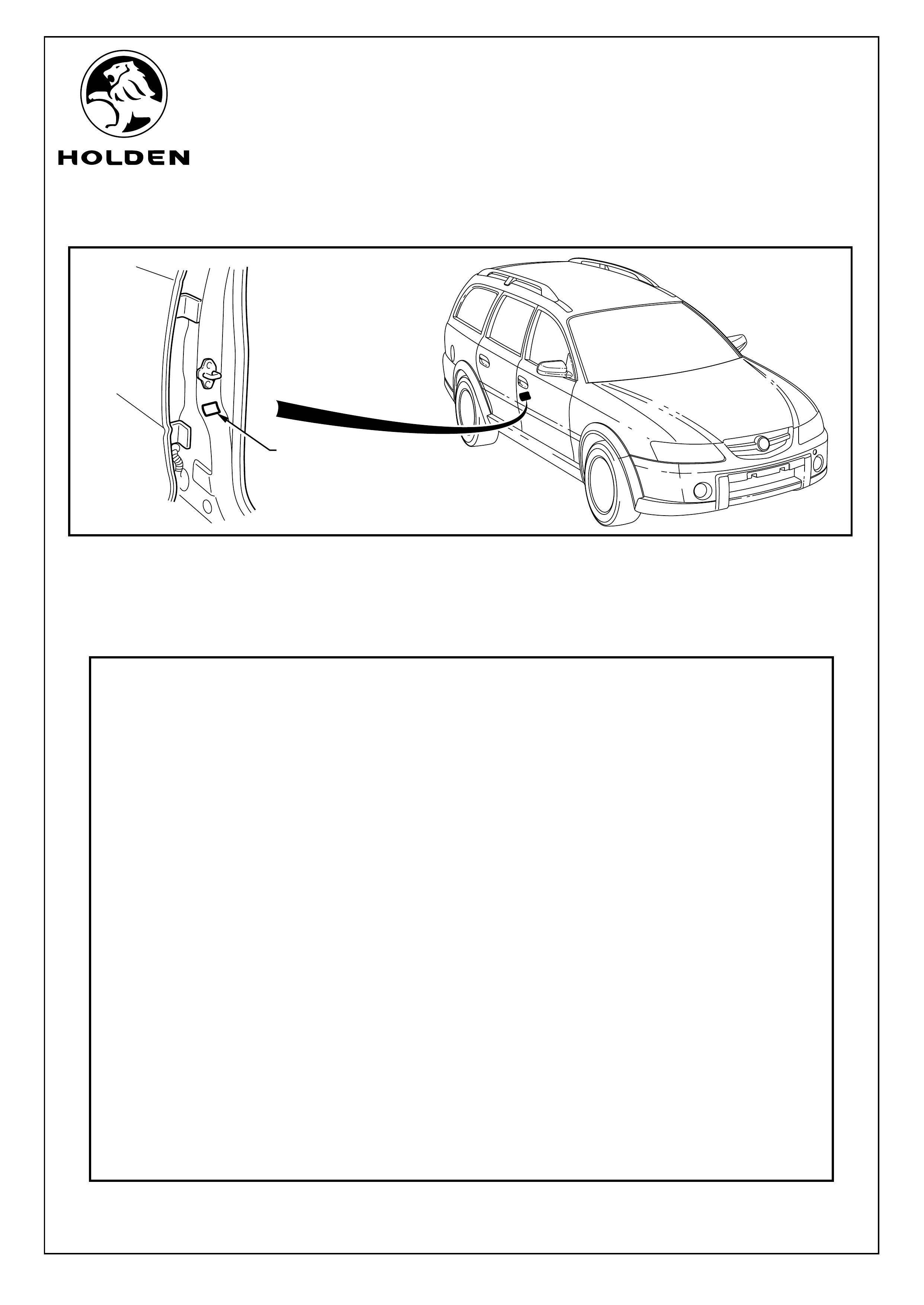
FIGURE 12
WIPE SURFACE CLEAN
PRIOR TO APPLICATION
OF ADR LABEL
37. Clean the surface of the driver's side B-pillar and apply ADR label supplied. Refer to Figure 12.
FITTING INSTRUCTIONS: - continued
For both 1600kg and 2100kg towbar tongue packages:
38. Place fitting instructions in vehicles glove box.