COPYRIGHT
Reproduction in whole or part
prohibited without written approval
HOLDEN LTD
Division of HOLDEN Ltd ACN 006 893 232
FD1240
24SEP04
FITTING INSTRUCTIONS FOR
REVERSE PARKING SENSOR SYSTEM
VY/VZ WAGON
Page 1 of 12
Part No. 92171982
NOTE: NOT SUITABLE IF TOWBAR IS FITTED TO THE VEHICLE.
COPYRIGHT
Reproduction in whole or part
prohibited without written approval
HOLDEN LTD
Division of HOLDEN Ltd ACN 006 893 232
FD1240
24SEP04
FITTING INSTRUCTIONS FOR
REVERSE PARKING SENSOR SYSTEM
VY/VZ WAGON
TOOLS REQUIRED:
Flat-blade Screwdriver, Phillips Head Screwdriver,
2.0 mm Drill Bit, Spade Drill Bit (P/N 92147946), Cleaning
Cloth, Hi-tech Cleaning Pad (Supplied), Guide Wire
(approx. 600 mm), Hammer, Long Drift, Masking Tape.
FITTING INSTRUCTIONS:
1. Copy and cut-out the templates on pages 11 - 12. Check
that the scale on the copied template is correct. Fit the
templates on the vehicle as indicated.
L-Left - Template 1 - Page 11.
CL - Centre Left - Template 2 - Page 11.
CR - Centre Right - Template 3 - Page 12.
R-Right - Template 4 - Page 12.
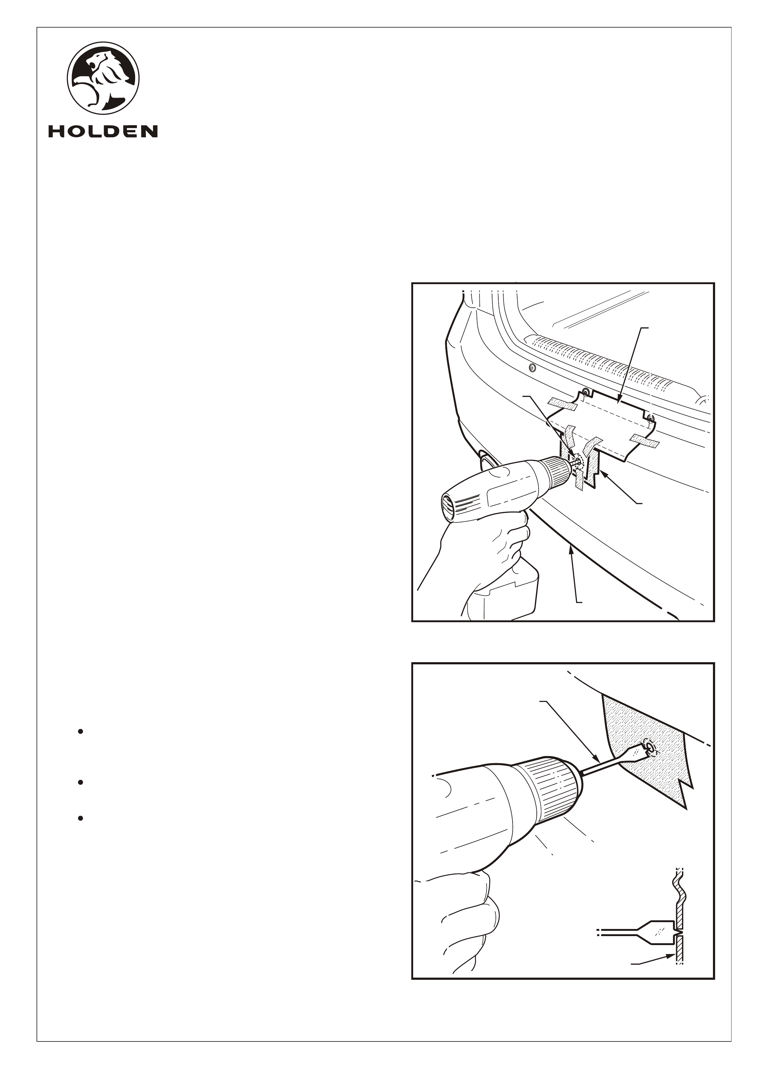
Place masking tape (1) over the area of the bumper (2)
fascia to be drilled. Refer to Figure 1.
2. Drill pilot holes (3) through the templates (4) and fascia
(4 places) using a 2.0 mm drill bit. Refer to Figure 1.
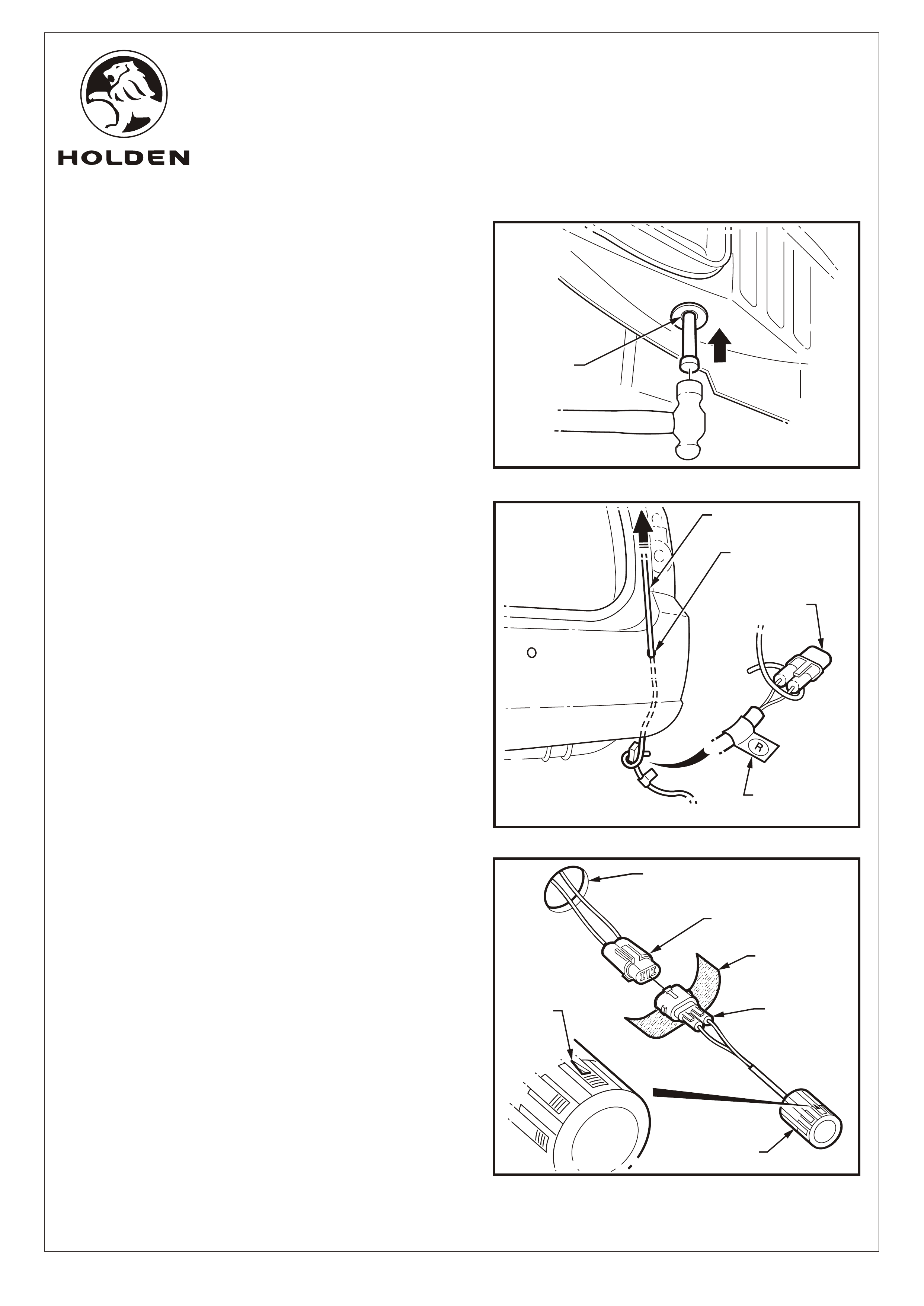
3. Remove the templates and use the spade bit (1) to make
22.2mm dia. holes (4 places) through the fascia (2).
Refer to Figure 2.
IMPORTANT:
Use only the spade drill bit as a normal drill bit or
hole saw may damage the bumper fascia.
Ensure the spade drill bit remains square with
the bumper fascia.
Use 1,500 - 2,000 RPM drill speed only to avoid
damaging the bumper fascia.
Ÿ
Ÿ
Ÿ
FIGURE 1
1
2
Page 2 of 12
FIGURE 2
3
4
1
2
COPYRIGHT
Reproduction in whole or part
prohibited without written approval
HOLDEN LTD
Division of HOLDEN Ltd ACN 006 893 232
FD1240
24SEP04
FITTING INSTRUCTIONS FOR
REVERSE PARKING SENSOR SYSTEM
VY/VZ WAGON
FITTING INSTRUCTIONS: - continued.
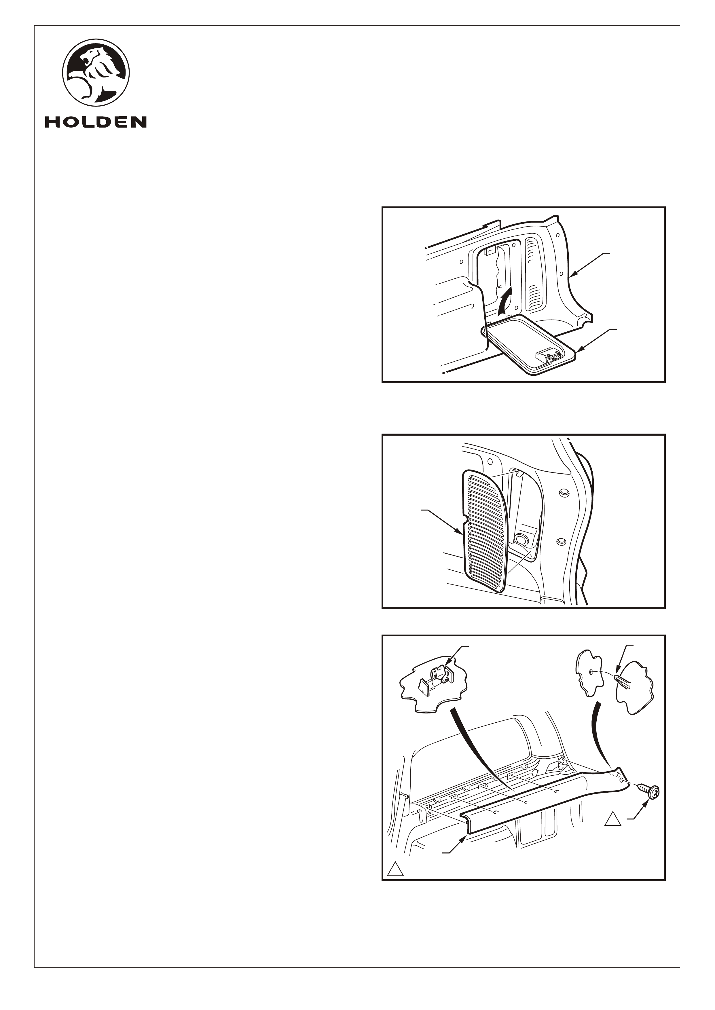
4. Open the door (1) in the trim panel (2) to a position lower
than horizontal. Remove the door vertically.
5. Lever the centre of the rear edge of the vent (1) away
from trim panel. Remove the vent.
Refer to Figure 5 for the following:
6. Remove the screw (1) retaining the upper trim (2).
7. Pull the rear edge of the upper trim away from the body
side panel and working forwards, disengage the garnish
clips (3) (4 places). Ensure that the garnish clips are
retained on the upper trim.
NOTE: When removing the upper trim ensure that care
is taken not to damage the locating pin (4).
FIGURE 3
FIGURE 4
2
1
1
1.0 - 3.0 Nm
1
33
1
1
2
Page 3 of 12
FIGURE 5
COPYRIGHT
Reproduction in whole or part
prohibited without written approval
HOLDEN LTD
Division of HOLDEN Ltd ACN 006 893 232
FD1240
24SEP04
FITTING INSTRUCTIONS FOR
REVERSE PARKING SENSOR SYSTEM
VY/VZ WAGON
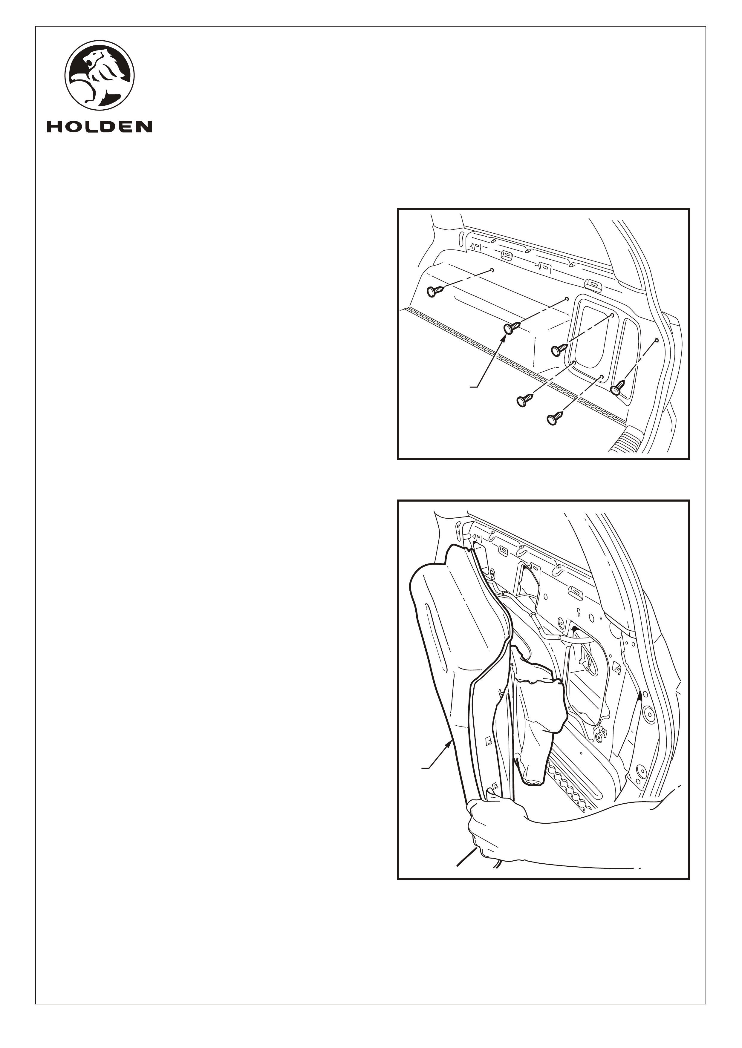
FITTING INSTRUCTIONS: - continued.
8. Remove the retainers (1) (7 places) on the quarter inner
trim panel assembly.
9. Remove the quarter inner trim panel assembly (1) by
raising the edge of the rear compartment floor carpet
and lifting it forward over the rear seat back striker.
FIGURE 6
FIGURE 7
Page 4 of 12
1
1
COPYRIGHT
Reproduction in whole or part
prohibited without written approval
HOLDEN LTD
Division of HOLDEN Ltd ACN 006 893 232
FD1240
24SEP04
FITTING INSTRUCTIONS FOR
REVERSE PARKING SENSOR SYSTEM
VY/VZ WAGON
FITTING INSTRUCTIONS: - continued.
Refer to Figure 8 for the following:
10. Remove the metal plug (1) from behind the right-hand
side wheel arch, by knocking it out from beneath the
vehicle.
11. From inside the rear compartment, clean sufficient
sealant from around the metal plug hole to allow the new
harness grommet to seal securely.
Refer to Figure 9 for the following:
12. Feed the reverse parking sensor (RPS) harness
connectors through the bumper fascia as follows:
a. Pass a piece of guide wire (1) through the right-
hand side fascia hole (2), down between the bumper
fascia and the bumper reinforcement.
b. Fix the right hand side connector (R) (3) to the wire
and pull back through the hole.
c. Use care when feeding the connector between the
fascia and bumper reinforcement.
d. Repeat for the centre-right (CR), the centre left (CL)
and the left (L) connectors.
NOTE: Ensure the harness connectors correspond to
the position of the sensors. This is indicated by a label
(4) situated behind the harness connector as follows:
L- Left
CL - Centre Left
CR - Centre Right
R- Right
Refer to Figure 10 for the following:
13. Peel the protective backing off the foam strip (1) and
wrap firmly around the sensor connector (2).
14. Connect the sensors to the RPS harness connectors (3)
15. Pass the connectors back through the holes (4) then
press fit the reverse parking sensors (5) (4 places) into
the holes drilled in the fascia.
IMPORTANT: Ensure the arrow (6) on the sensor
body is positioned at the top of the sensor when
fitted to the fascia.
FIGURE 8
5
2
1
3
4
6
1
FIGURE 9
2
1
4
3
Page 5 of 12
FIGURE 10
COPYRIGHT
Reproduction in whole or part
prohibited without written approval
HOLDEN LTD
Division of HOLDEN Ltd ACN 006 893 232
FD1240
24SEP04
FITTING INSTRUCTIONS FOR
REVERSE PARKING SENSOR SYSTEM
VY/VZ WAGON
FITTING INSTRUCTIONS: - continued.
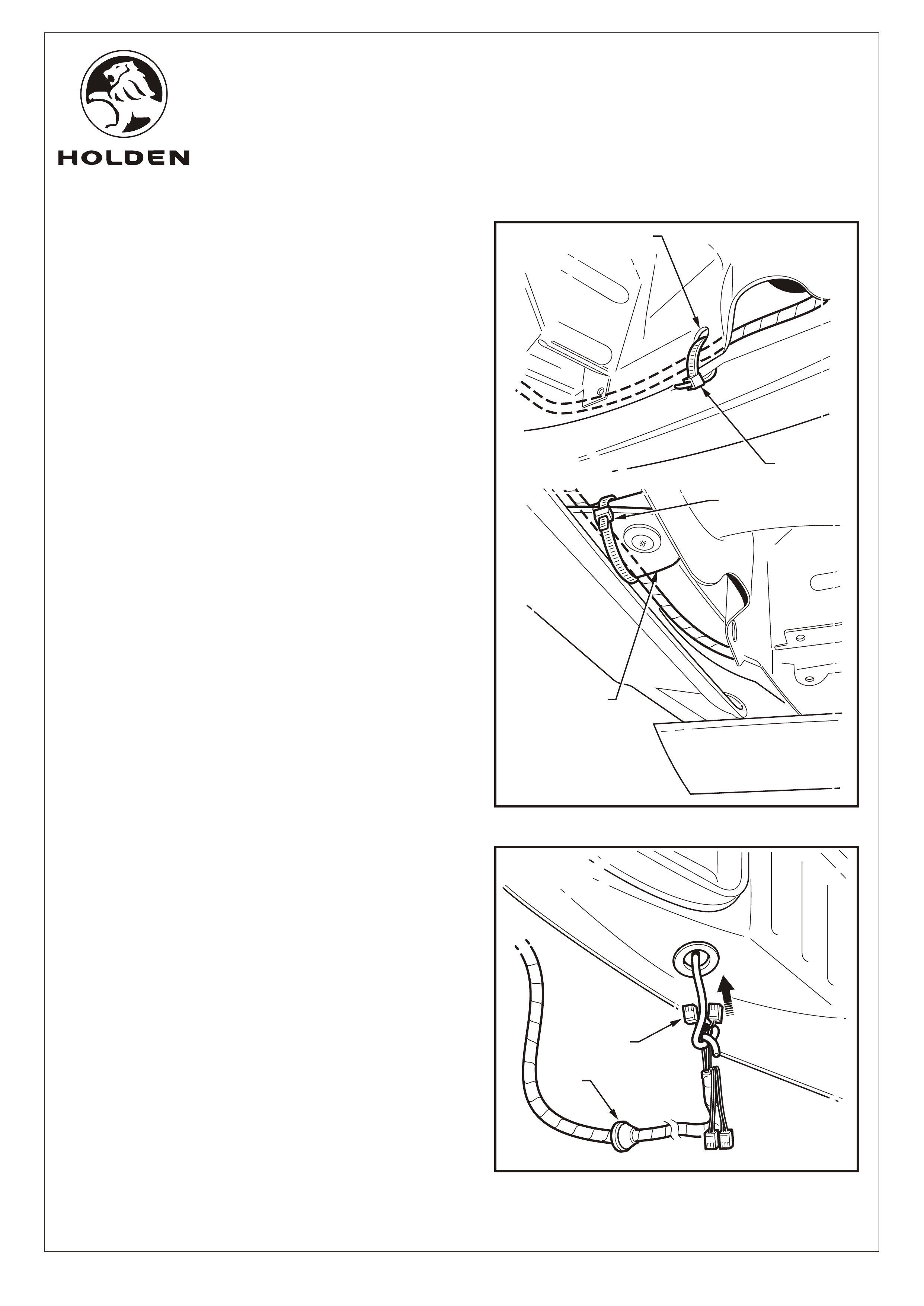
Refer to Figure 11 for the following:
16. Tie strap the RPS harness (2 places) as follows:
a. Tie strap (1) securely to the hole (2) on the right-
hand side of the lower rear panel.
b. Tie strap (3) loosely to the left-hand side bumper
fascia support bracket (4).
17. Feed the RPS harness module connectors (1) through
the hole behind the right-hand side rear wheel arch, and
fit the grommet (2) securely in position. Refer to Figure
12.
NOTE: Ensure the grommet mounting hole surround is
clean and free from sealant.
FIGURE 11
3
4
1
2
FIGURE 12
2
1
Page 6 of 12
COPYRIGHT
Reproduction in whole or part
prohibited without written approval
HOLDEN LTD
Division of HOLDEN Ltd ACN 006 893 232
FD1240
24SEP04
FITTING INSTRUCTIONS FOR
REVERSE PARKING SENSOR SYSTEM
VY/VZ WAGON
FITTING INSTRUCTIONS: - continued.
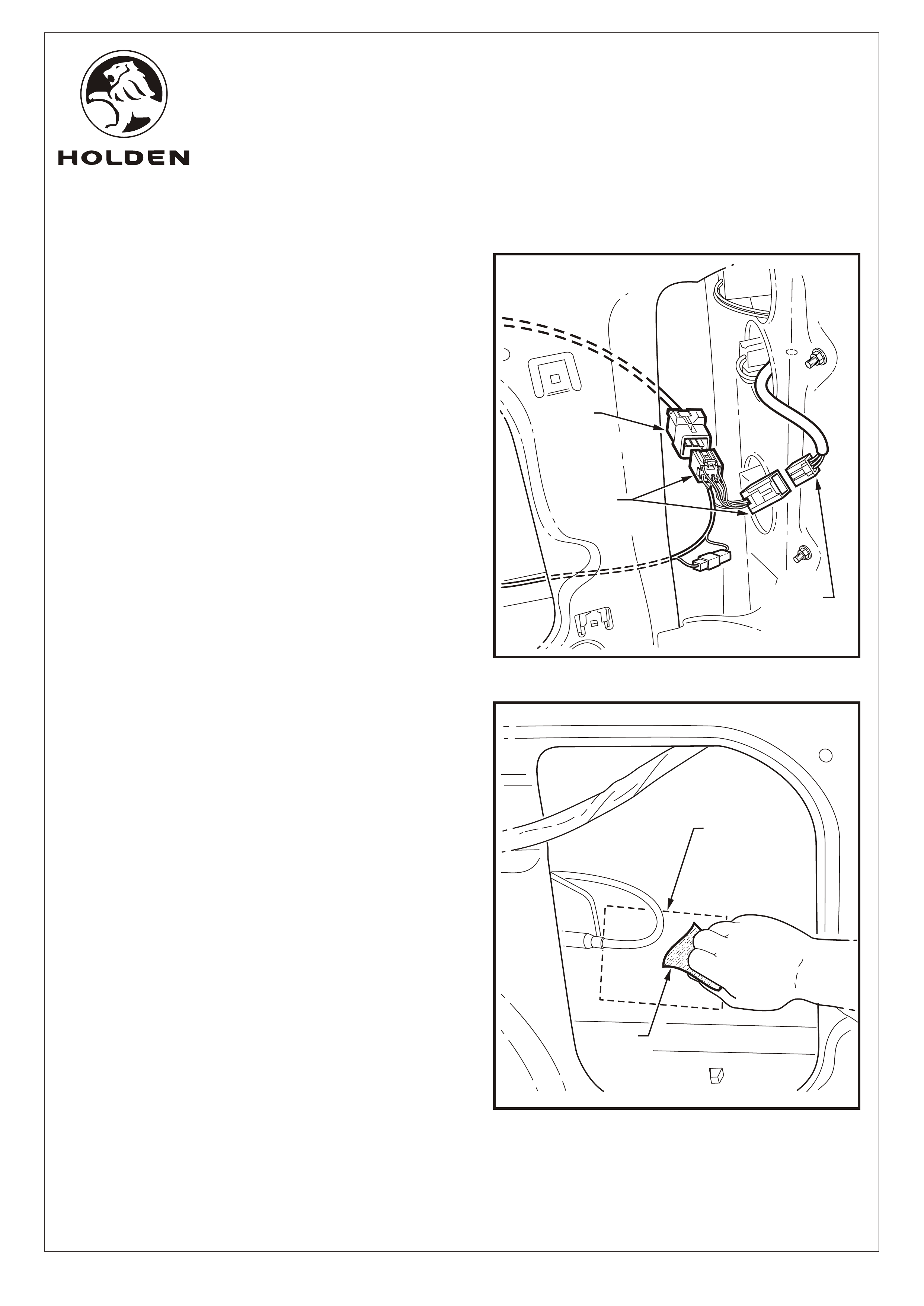
Refer to Figure 13 for the following:
18. Disconnect the existing right-hand side rear
compartment tail light connector (1) from the connector
on the body wiring haness (2).
19. Fit the corresponding connectors on the RPS main
wiring harness (3) between the connectors on the right-
hand side rear compartment tail light harness.
20. The RPS module mounts on the inside of the right-hand
side rear quarter panel behind the wheel arch as
indicated (1).
NOTE: Before fitting the module, clean the mounting
area then wipe with the hi-tech cleaning pad (2) supplied
(retain pad for later use). Also wipe the back of the RPS
module. Refer to Figure 14.
2
3
1
2
FIGURE 13
1
Page 7 of 12
FIGURE 14
COPYRIGHT
Reproduction in whole or part
prohibited without written approval
HOLDEN LTD
Division of HOLDEN Ltd ACN 006 893 232
FD1240
24SEP04
FITTING INSTRUCTIONS FOR
REVERSE PARKING SENSOR SYSTEM
VY/VZ WAGON
1
4
3
2
FIGURE 15
5
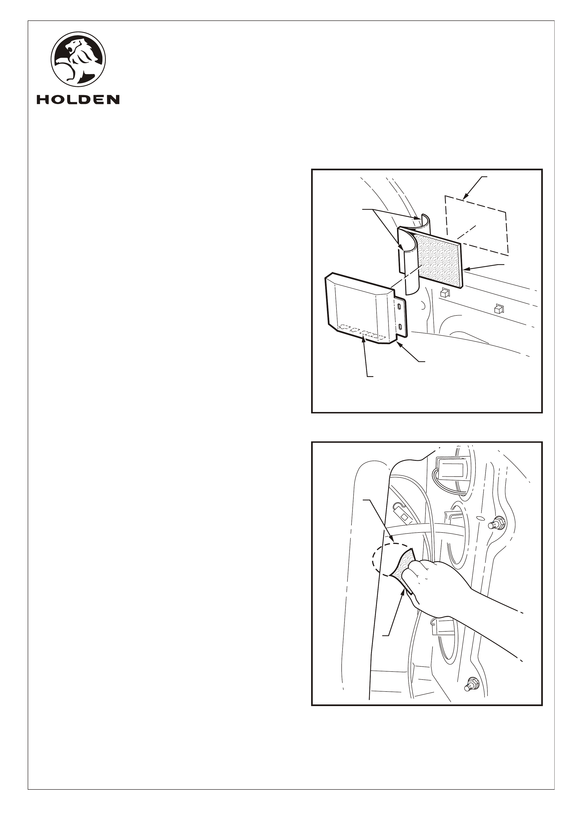
FITTING INSTRUCTIONS: - continued.
Refer to Figure 15 for the following:
21. Peel the backing (1) off one side of the RPS module
velcro mounting pad (2) and press fit firmly to the back of
the RPS module (3).
22. Peel the backing off the remaining side of the velcro
mounting pad and press fit the RPS module onto the
inner rear quarter panel in the position indicated (4),
ensuring the WIRING CONNECTOR SOCKETS (5)
FACE "DOWN". Apply pressure to the RPS module unit
to ensure a secure fit.
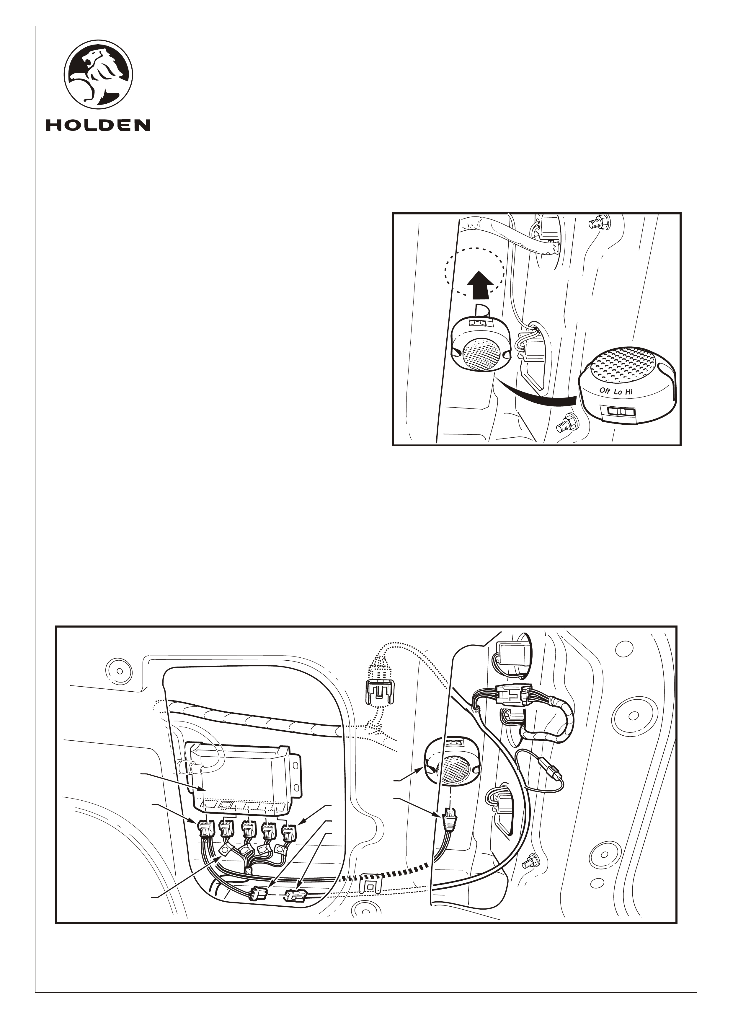
23. The RPS buzzer mounts in the right rear quarter panel
(1) as indicated. Clean the mounting area then wipe with
the hi-tech cleaning pad (2) supplied (retain pad for later
use). Refer to Figure 16.
2
1
Page 8 of 12
FIGURE 16
COPYRIGHT
Reproduction in whole or part
prohibited without written approval
HOLDEN LTD
Division of HOLDEN Ltd ACN 006 893 232
FD1240
24SEP04
FITTING INSTRUCTIONS FOR
REVERSE PARKING SENSOR SYSTEM
VY/VZ WAGON
FITTING INSTRUCTIONS: - continued.
Refer to Figure 17 for the following:
24. Peel the protective backing off the RPS buzzer and
press fit in the position indicated ensuring the WIRING
SOCKET FACES "DOWN". Apply pressure to the
buzzer unit to ensure a secure fit.
NOTE: Prior to fitting the buzzer, ensure the switch is set
to 'Hi'.
Refer to Figure 18 for the following:
25. Connect the RPS buzzer harness connector (1) to the
buzzer (2).
26. Connect the RPS buzzer harness connector (3) to the
connector (4) on the RPS power harness.
27. Connect the four RPS harness connectors (5) into the
corresponding positions on the RPS module (6). The
connectors on the RPS main harness are identified with
labels (7) as follows:
L- Left
CL - Centre Left
CR - Centre Right
R- Right
28. Connect the connector (8) on the RPS power harness to
the RPS module.
29. Neatly cable tie excess wiring harness.
LL
CL
CL
CR
CR
R
R
CL
CR
6
L
R
8
7
1
5
FIGURE 17
OffOff
LoLo
HiHi
OffOff
LoLo
HiHi
Page 9 of 12
FIGURE 18
2
3
4
COPYRIGHT
Reproduction in whole or part
prohibited without written approval
HOLDEN LTD
Division of HOLDEN Ltd ACN 006 893 232
FD1240
24SEP04
FITTING INSTRUCTIONS FOR
REVERSE PARKING SENSOR SYSTEM
VY/VZ WAGON
PARTS LIST
FITTING INSTRUCTIONS: - continued.
30. Locate a suitable position for the caution label (above
tyre placard on drivers side door). Clean the area using
the hi-tech cleaning pad. Attach the caution label.
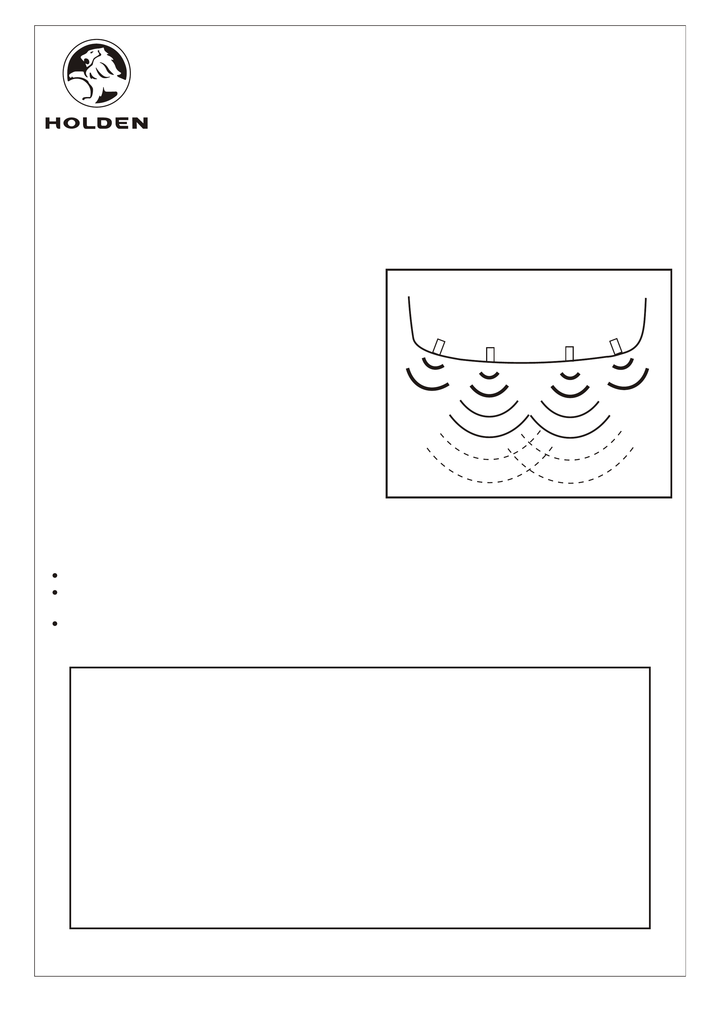
31. Test the reverse parking sensor system for correct
operation as follows:
Turn the ignition to the "ON" position (engine not
running).
Place the gear lever in reverse (R).
From behind the vehicle, walk towards each sensor.
The two centre sensors have 3 stages.
The two corner sensors only have 1 stage of final
warning. Refer to Figure 20.
Refer to the owners manual for further information
and trouble shooting.
Turn the ignition to the "OFF" position.
32. Refit all removed parts and torque fasteners to
specifications.
33. Place fitting instructions in the glovebox.
IMPORTANT:
DO NOT paint over the reverse parking sensor.
Ensure the reverse parking sensor remains clean
and free from road grime, mud, car polish etc.
If the sensor or the groove on the sensor surface
becomes contaminated, the performance may be
affected.
Ÿ
Ÿ
Ÿ
PART NUMBER DESCRIPTION QUANTITY
92171982 REVERSE PARKING SENSOR SYSTEM
REVERSE PARKING SENSOR MAIN HARNESS 1
REVERSE PARKING SENSOR HARNESS 1
REVERSE PARKING SENSOR BUZZER HARNESS 1
REVERSE PARKING SENSOR 4
REVERSE PARKING BUZZER 1
REVERSE PARKING SENSOR MODULE VELCRO MOUNTING PAD 1
REVERSE PARKING SENSOR FOAM SEAL 4
REVERSE PARKING SENSOR BUZZER HARNESS ADHESIVE PADS 2
CABLE TIE 10
HI-TECH CLEANING PAD 1
INSTRUCTION MANUAL 1
FD1240 FITTING INSTRUCTIONS 1
FD796 PROOF OF WARRANTY CARD 1
FIGURE 19
Page 10 of 12