FITTING INSTRUCTIONS FOR
REAR POWER OUTLET
FD1292
14SE04
COPYRIGHT
Reproduction in whole or part
prohibited without written approval
HOLDEN LTD
Division of HOLDEN Ltd ACN 006 893 232
Page 1 of 15
TOOLS REQUIRED:
Knife, Marker, Masking Tape, Phillips Screwdriver, Scriber, Side Cutters, Small Flat Screwdriver, 10mm Spanner,
Tape Measure, Torx 24 Bit, (Pointed Pliers, Power Drill, 5.5mm Drill Bit, Wagon only).
Part No. 92171326
FITTING INSTRUCTIONS FOR
REAR POWER OUTLET
FD1292
14SE04
COPYRIGHT
Reproduction in whole or part
prohibited without written approval
HOLDEN LTD
Division of HOLDEN Ltd ACN 006 893 232
FIGURE 1
1
A-A
A
A
A
A
2
2
(3 PLACES)
3
(2 PLACES)
FIGURE 2
FITTING INSTRUCTIONS:
Sedan and Wagon
1. Turn the ignition to the “OFF” position.
2. Disconnect the vehicle's battery.
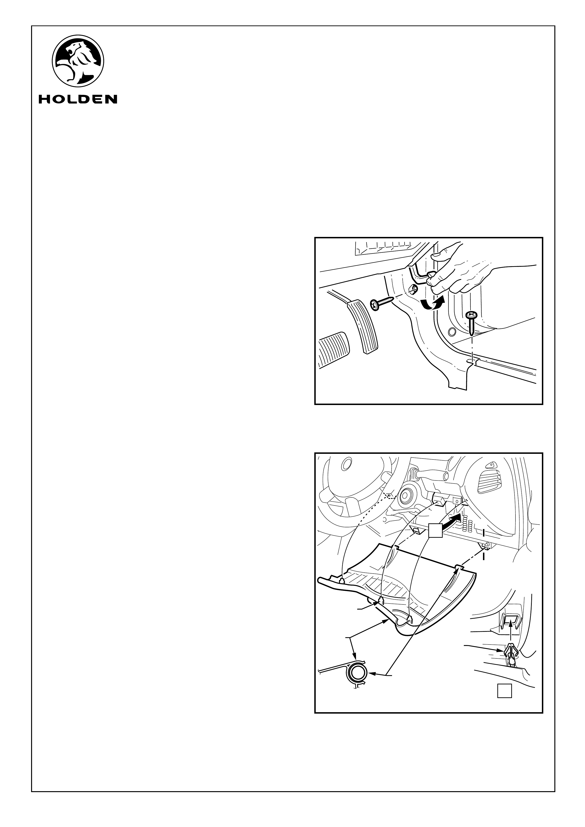
Refer to Figure 1 for the following:
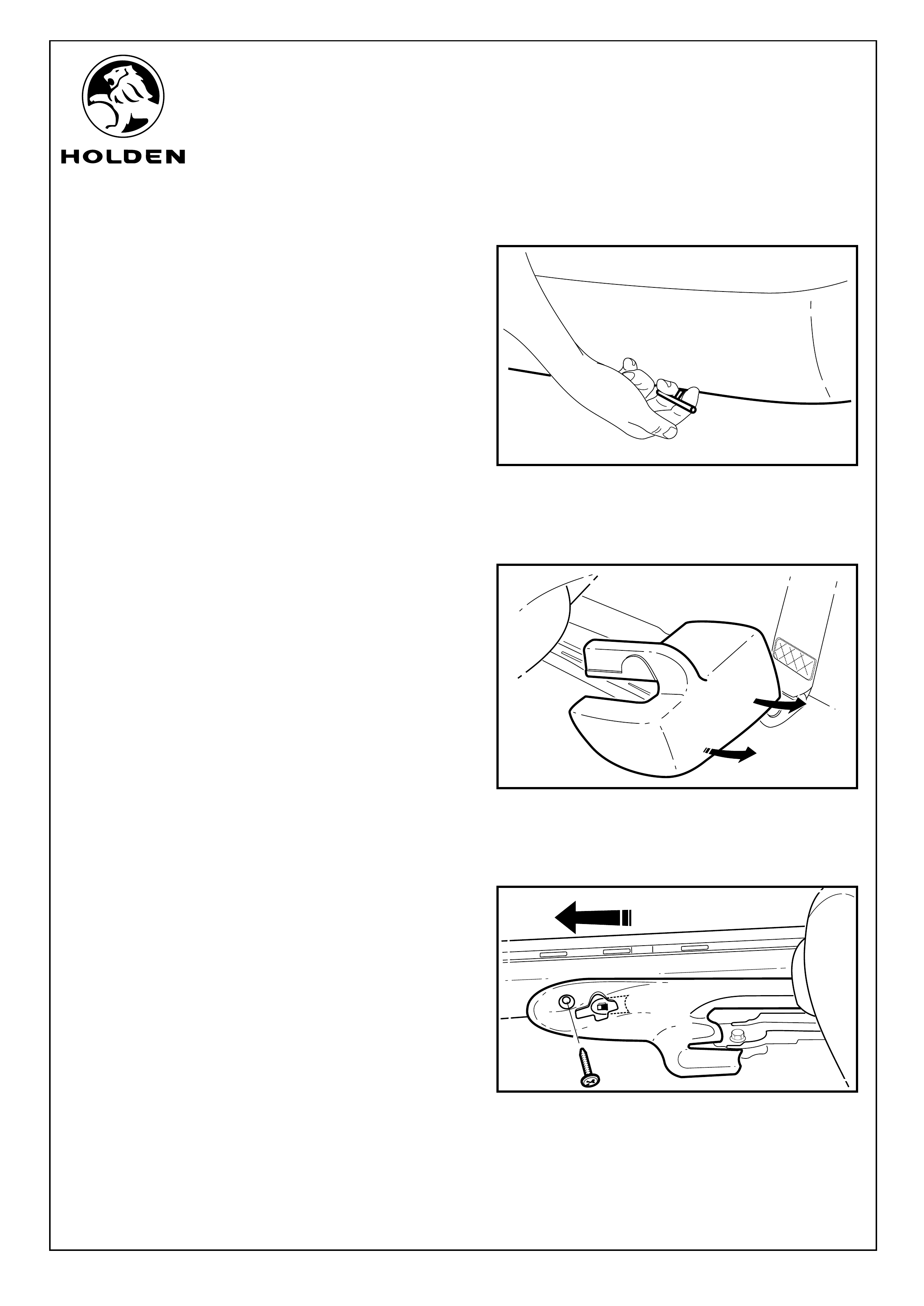
3. Remove the screws (2 places) holding the front drivers
side kick plate in position and pull back on the front kick
plate to release the two clips. Remove the side kick
plate.
NOTE: The Bonnet release handle will need to be pulled
back to expose the screw head of one of the screws.
Refer to Figure 2 for the following:
4. Remove the lower instrument trim panel (1) assembly
as follows:
a. Adjust the steering wheel to upper-most position.
b. Grasp the upper edge of the lower instrument trim
panel assembly and pull outwards to disengage the
three retaining clips (2).
c. Swing the panel assembly open.
d. Holding each side of the panel assembly pull
rearwards to disengage it from the instrument panel
lower trim panel retainer (3) (2 places).
Page 2 of 15
FITTING INSTRUCTIONS FOR
REAR POWER OUTLET
FD1292
14SE04
COPYRIGHT
Reproduction in whole or part
prohibited without written approval
HOLDEN LTD
Division of HOLDEN Ltd ACN 006 893 232
FITTING INSTRUCTIONS: - continued...
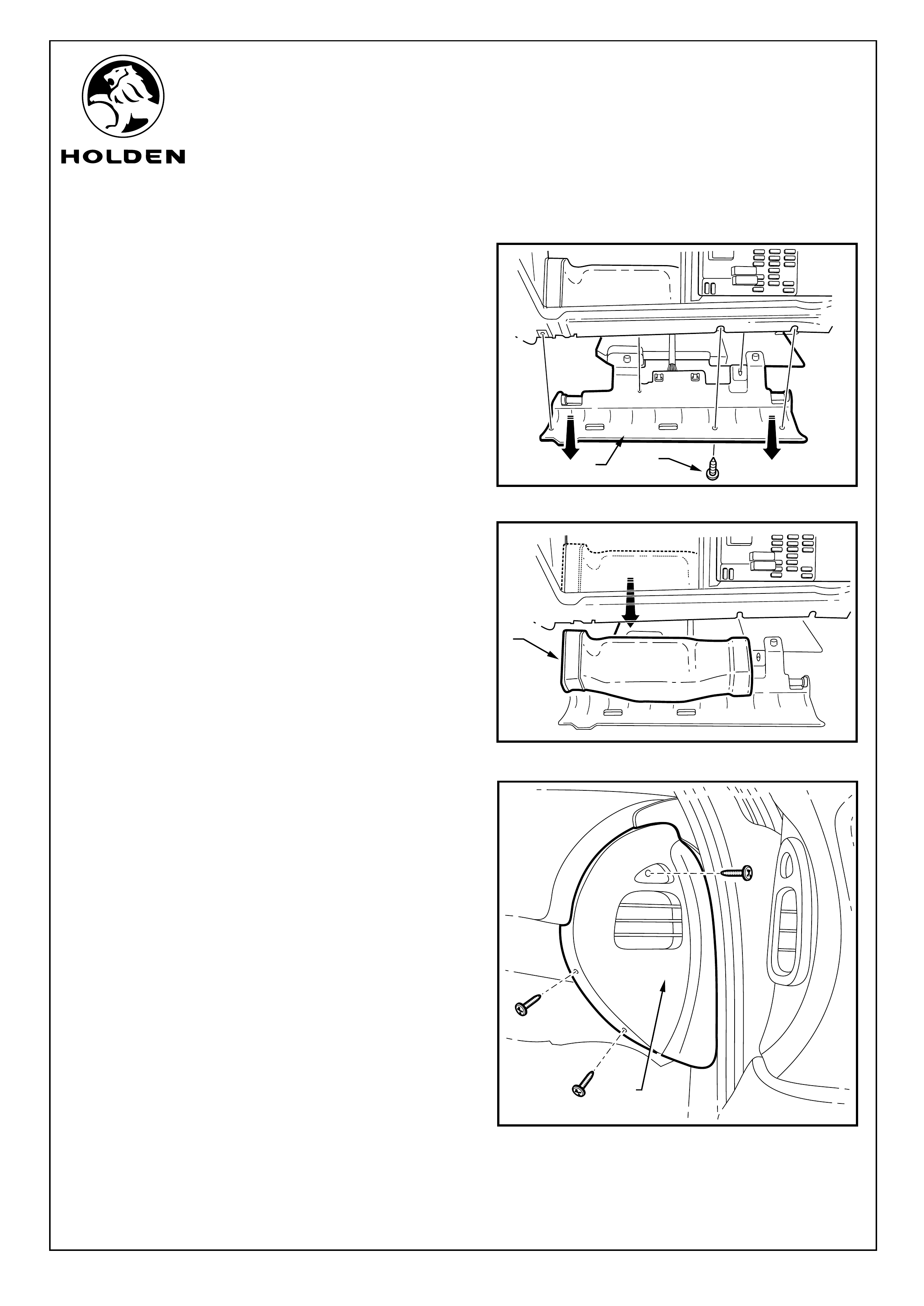
5. On the driver's side, remove the screws (1) (5 places)
holding the hush panel (2). Slide the panel downward
and rearward to remove and allow it to hang down. Refer
to Figure 3
6. On the driver's side, remove the lower air duct (1) by
pushing outboard and pulling down. Refer to Figure 4
7. Remove the screws (3 places) retaining the drivers side
dashboard end cover (1) and remove. Refer to Figure 5
FIGURE 4
FIGURE 3
Page 3 of 15
1
1
FIGURE 5
1
2
FITTING INSTRUCTIONS FOR
REAR POWER OUTLET
FD1292
14SE04
COPYRIGHT
Reproduction in whole or part
prohibited without written approval
HOLDEN LTD
Division of HOLDEN Ltd ACN 006 893 232
FITTING INSTRUCTIONS: - continued...
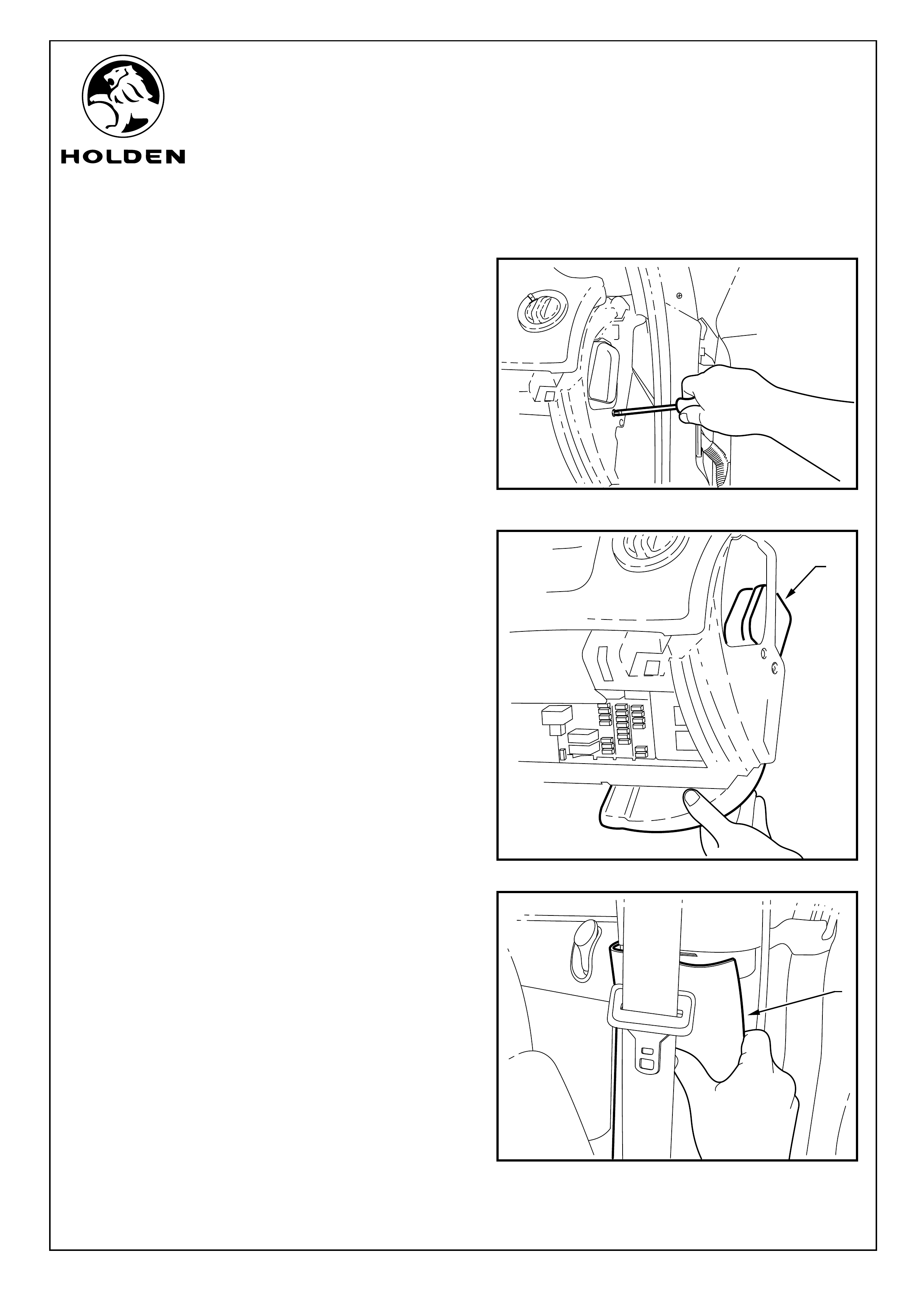
8. Remove the screw holding the air duct in position. Refer
to Figure 6
Refer to Figure 7 for the following: (drivers side only).
9. Push the duct (1) into the dash and rotate the duct
towards the front of the vehicle whilst pulling the duct
down and out from the dashboard.
10. Pull off the drivers lower “B” pillar trim panel (1).
Refer to Figure 8.
FIGURE 7
Page 4 of 15
FIGURE 6
1
1
FIGURE 8
FITTING INSTRUCTIONS FOR
REAR POWER OUTLET
FD1292
14SE04
COPYRIGHT
Reproduction in whole or part
prohibited without written approval
HOLDEN LTD
Division of HOLDEN Ltd ACN 006 893 232
FITTING INSTRUCTIONS: - continued...
11. Pull the release handles (2 place) under the rear seat
base and remove the seat base. Refer to Figure 9
12. Unclip the rear section of the front seat rail cover (driver
side only) by pushing down on the join between the front
and rear covers and pull the rear cover back and up to
remove. Refer to Figure 10.
13. Remove screw from behind fuel release lever (drivers
side only). Slide the front section of the front seat rail
cover out towards the front of the vehicle. Refer to
Figure 11.
Page 5 of 15
FIGURE 9
FIGURE 10
FIGURE 11
FITTING INSTRUCTIONS FOR
REAR POWER OUTLET
FD1292
14SE04
COPYRIGHT
Reproduction in whole or part
prohibited without written approval
HOLDEN LTD
Division of HOLDEN Ltd ACN 006 893 232
FITTING INSTRUCTIONS: - continued...
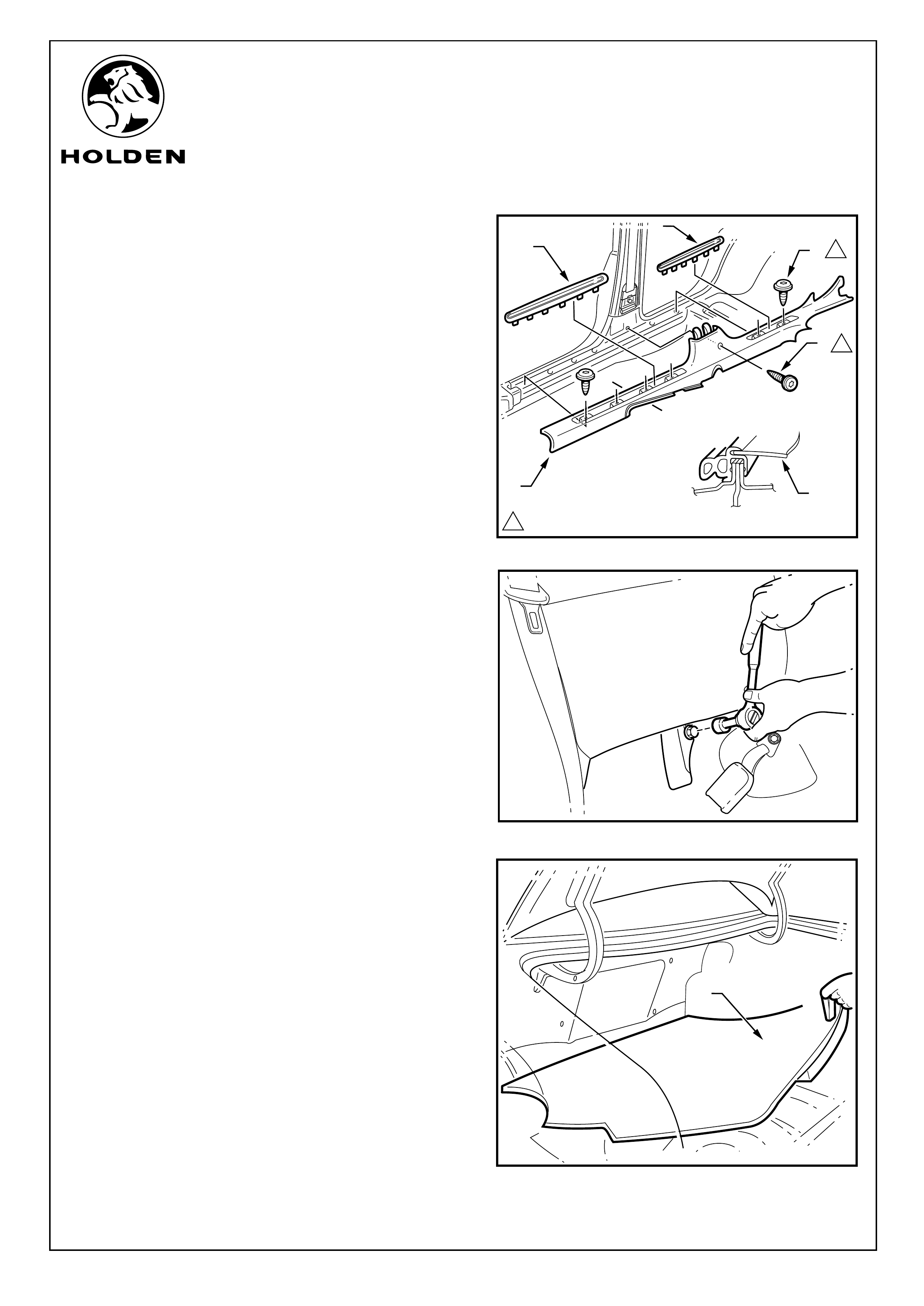
Refer to Figure 12 for the following:
14. Carefully lever the front and rear side sill trim plates (1)
from the side sill trim (2), starting at the front of each
plate and moving rearwards, revealing the attaching
screws.
CAUTION: Take care not to break the sill trim plates.
15 Remove the Torx head screws (3) (4 places in front door
opening, 2 places rear door opening) from the side sill
trim.
16 Remove the screw (4) from the side sill trim to the centre
pillar.
17. Remove the side sill trim.
(Ste ) SEDAN ONLY
18 Use a socket to remove the bolt securing the rear drivers
side seat back. Push up on the seat back to release and
remove from the vehicle. Refer to Figure 13.
19. Remove the rear compartment floor carpet assembly (1)
from the vehicle. Refer to Figure 14.
ps 18 - 24
FIGURE 12
FIGURE 13
Page 6 of 15
1.0 - 3.0 Nm
1
1
1
1
A-A
A
A
2
4
3
2
1
FIGURE 14
1
FITTING INSTRUCTIONS FOR
REAR POWER OUTLET
FD1292
14SE04
COPYRIGHT
Reproduction in whole or part
prohibited without written approval
HOLDEN LTD
Division of HOLDEN Ltd ACN 006 893 232
FITTING INSTRUCTIONS: - continued...
27. Open the door (1) on drivers side of wagon boot trim
Refer to Figure 17.
Refer to Figure 15 for the following:
20. Carefully prise off the drivers side rear shock absorber
cover (1).
21. Using a trim removing tool, carefully remove the retainer
(2) away from the drivers side quarter inner rear side
carpet (3).
22. Unhook the carpet flap from the rear compartment lid
hinge bracket.
23. Carefully remove the drivers side rear quarter inner
carpet.
24. Disconnect the rear boot net (if fitted) and unscrew and
remove the drivers side boot net fixing (4)
(Ste WAGON ONLY
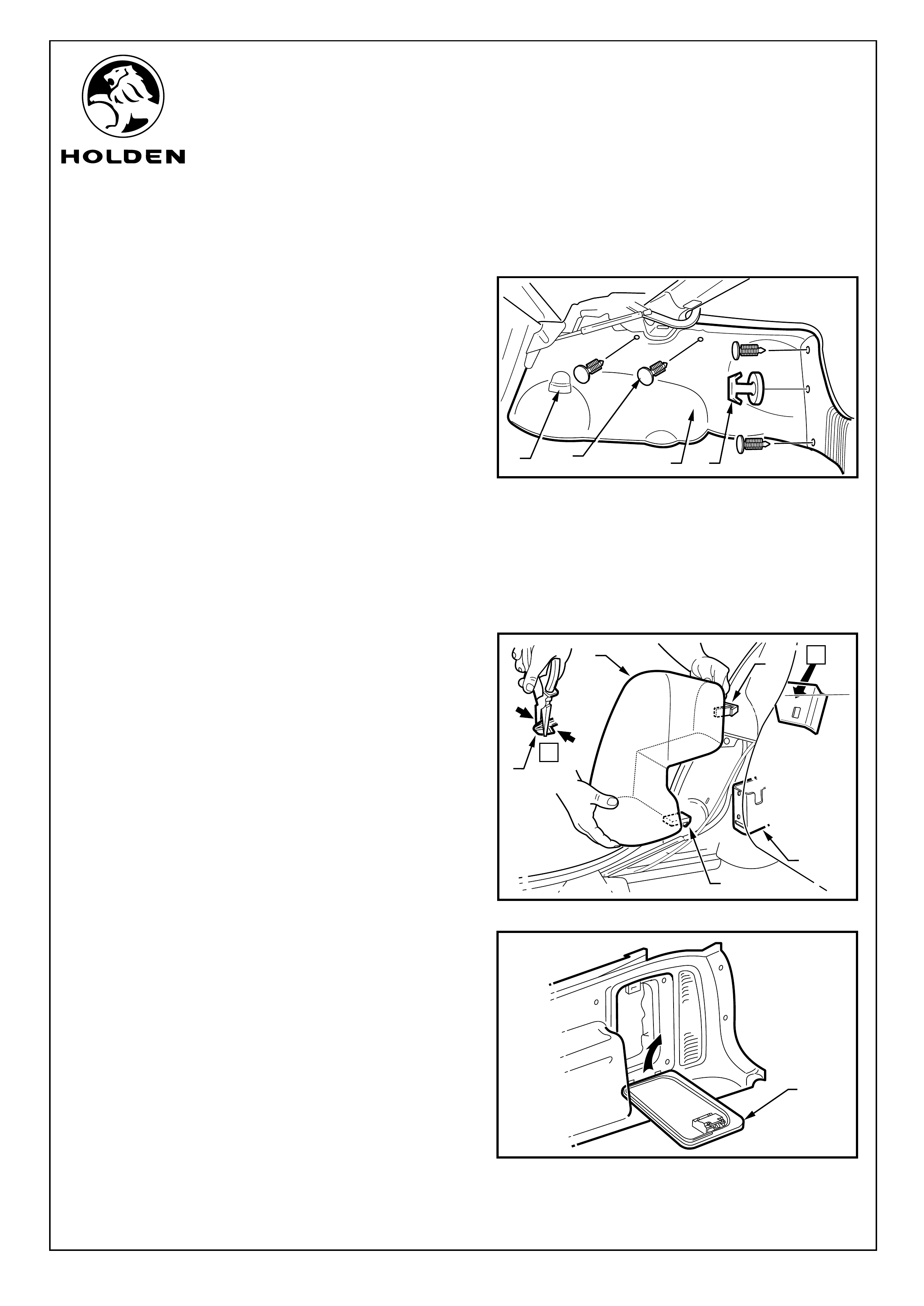
Refer to Figure 16 for the following:
25. Using pliers, squeeze the tangs of the rear drivers side
seat upper bolster retaining clip (1) together and pull the
rear bolster assembly (2) towards the front of the
vehicle.
26. To disengage, lift the lower retainer retaining tang (3) up
and pull the bolster forward, out of the seat-back
retaining bracket (4) towards the front of the vehicle.
ps 25 - 32)
FIGURE 15
Page 7 of 15
123 4
FIGURE 17
1
FIGURE 16
A
A
2
1
1
4
3

FITTING INSTRUCTIONS FOR
REAR POWER OUTLET
FD1292
14SE04
COPYRIGHT
Reproduction in whole or part
prohibited without written approval
HOLDEN LTD
Division of HOLDEN Ltd ACN 006 893 232
FITTING INSTRUCTIONS: - continued...
28. Lever the centre of the rear edge of the vent (1) away
from trim panel on the drivers side. Refer to Figure 18.
Refer to Figure 19 for the following:
29. Remove the screw (1) retaining the upper trim on the
drivers side (2).
30. Pull the rear edge of the upper trim away from the body
side panel and working forwards, disengage the garnish
clips (3) (4 places). Ensure that the garnish clips are
retained on the upper trim.
NOTE: When removing the upper trim ensure that care
is taken not to damage the locating pin (4).
31. Use a trim removal tool to remove the retainers (1) (7
places) on the quarter inner trim panel assembly. Refer
to Figure 20.
FIGURE 18
1
Page 8 of 15
1.0 - 3.0 Nm
1
34
1
1
2
FIGURE 19
FIGURE 20
1
FITTING INSTRUCTIONS FOR
REAR POWER OUTLET
FD1292
14SE04
COPYRIGHT
Reproduction in whole or part
prohibited without written approval
HOLDEN LTD
Division of HOLDEN Ltd ACN 006 893 232
FITTING INSTRUCTIONS: - continued.
32. Remove the driver side boot quarter trim panel
assembly (1) by raising the edge of the rear
compartment floor carpet and lifting it forward over the
rear seat back striker. Refer to Figure 21.
Sedan and Wagon
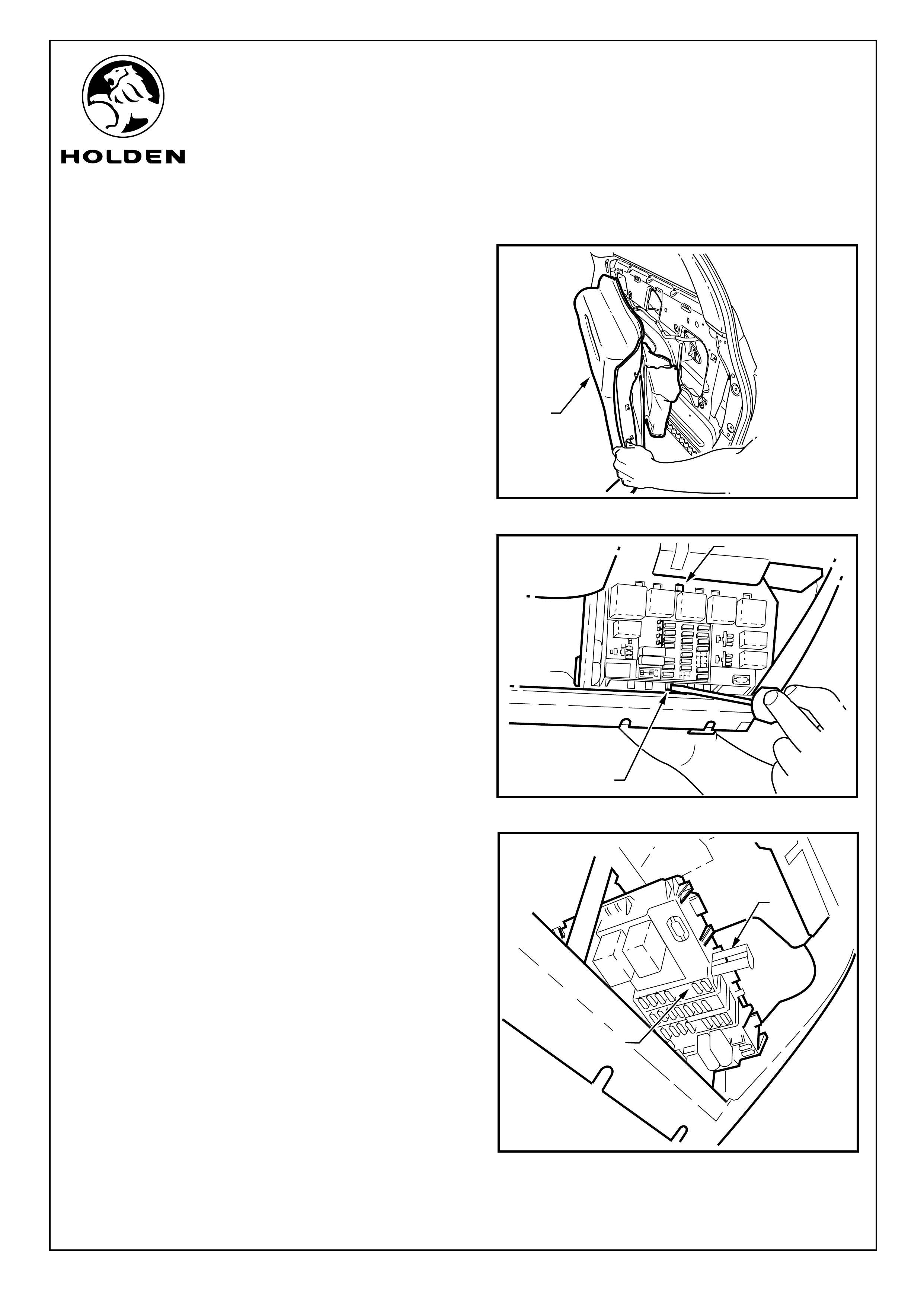
Refer to Figure 22 for the following:
33. Identify fuse position 25.
34. Release the main fuse and relay panel by using a small
flat bladed screwdriver to push in the top and bottom
locking tabs (1), slide the fuse panel to the left and push
the panel inwards.
35. Push the fuse and relay panel into the dash and remove
the back-out protector (1) for the column that houses
fuse 25 (2). Refer to Figure 23.
FIGURE 21
1
Page 9 of 15
-10- -10-
-15- -15-
-10-
-10-
-15-
-15-
-15- -15-
-15- -15- -15- -15-
-15- -15-
-15-
-15-
-10- -10-
-10-
-10-
-20- -20-
-7.5- -7.5-
-7.5- -7.5-
-7.5-
-7.5-
-7.5- -7.5-
-20- -20-
-20- -20-
-20-
-20-
-10- -10-
FIGURE 22
1
1
FIGURE 23
1
2
FITTING INSTRUCTIONS FOR
REAR POWER OUTLET
FD1292
14SE04
COPYRIGHT
Reproduction in whole or part
prohibited without written approval
HOLDEN LTD
Division of HOLDEN Ltd ACN 006 893 232
FITTING INSTRUCTIONS: - continued...
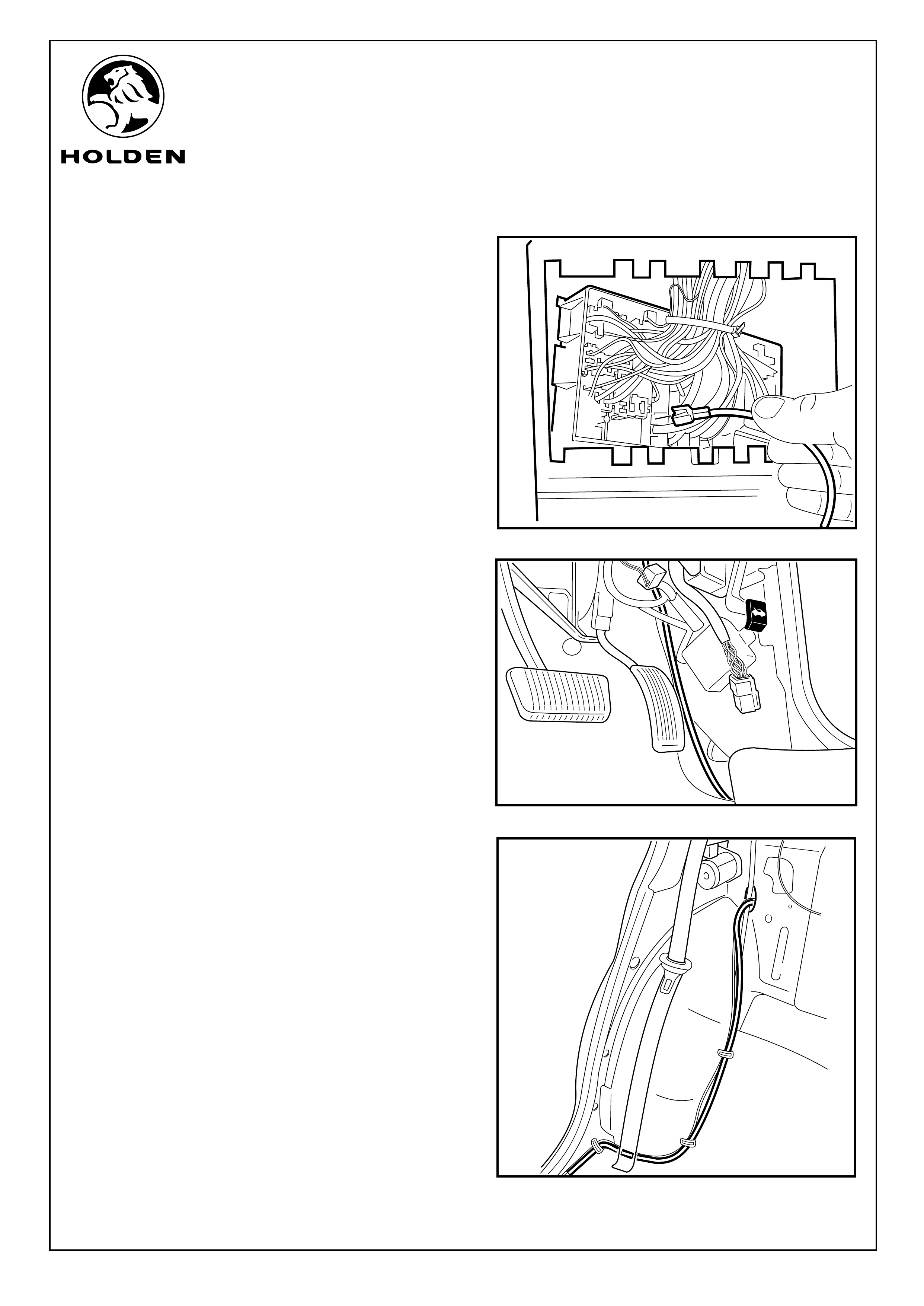
Refer to Figure 24 for the following:
36. Insert the power outlet harness terminal into position 25
and refit the back-out protector.
37. Turn the fuse panel around and refit into the fuse panel
carrier and slide across to the lock position.
38. Run the power outlet harness from the fuse panel, down
the side of the vehicle behind the bonnet release cable.
Refer to Figure 25.
39. Run the power outlet harness along the drivers side
inner sill. Apply cable ties at vehicle body mounted
cable tie positions.
s 40 - 46
40. Run along
.
(Step ) SEDAN ONLY
the wheel arch, through the hole in the rear
seat back panel Refer to Figure 26.
FIGURE 24
Page 10 of 15
FIGURE 25
FIGURE 26
FITTING INSTRUCTIONS FOR
REAR POWER OUTLET
FD1292
14SE04
COPYRIGHT
Reproduction in whole or part
prohibited without written approval
HOLDEN LTD
Division of HOLDEN Ltd ACN 006 893 232
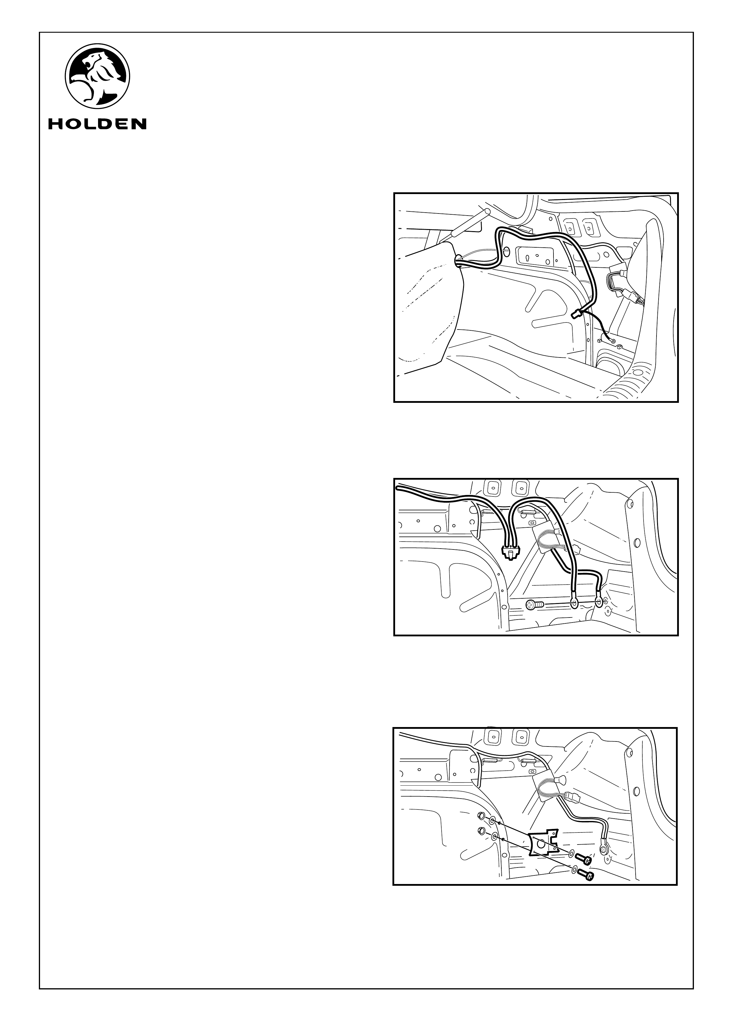
FITTING INSTRUCTIONS: - continued...
41. Run the power outlet harness along the vehicle body
harness. Cable tie power outlet harness at the same
positions as body harness fixing points. Refer to
Figure 27.
42. Fit the power outlet earth wire to the drivers side rear
light earthing point. Refer to Figure 28.
43. Use nuts, bolts and washers supplied (2 places) to
attach the power outlet bracket in position in the
orientation shown. Refer to Figure 29.
Page 11 of 15
FIGURE 27
FIGURE 28
FIGURE 29
FITTING INSTRUCTIONS FOR
REAR POWER OUTLET
FD1292
14SE04
COPYRIGHT
Reproduction in whole or part
prohibited without written approval
HOLDEN LTD
Division of HOLDEN Ltd ACN 006 893 232
FIGURE 31
FIGURE 32
FITTING INSTRUCTIONS: - continued...
Refer to Figure 30 for the following:
44. Refit the drivers side rear quarter panel carpet. Fold
back to expose the mounting bracket socket hole and
mark the carpet by pushing a scriber through the carpet
into the socket hole in the bracket.
45. On the carpet, mark the position of the centre of the
power outlet hole. Use a sharp knife to remove the
carpet from within the circle in the bracket, also remove
the carpet from the notch at the base of the circle.
46. Fold back the carpet and pass the power outlet
connector through the hole and refit carpet.
(Steps 47 - 63) WAGON ONLY
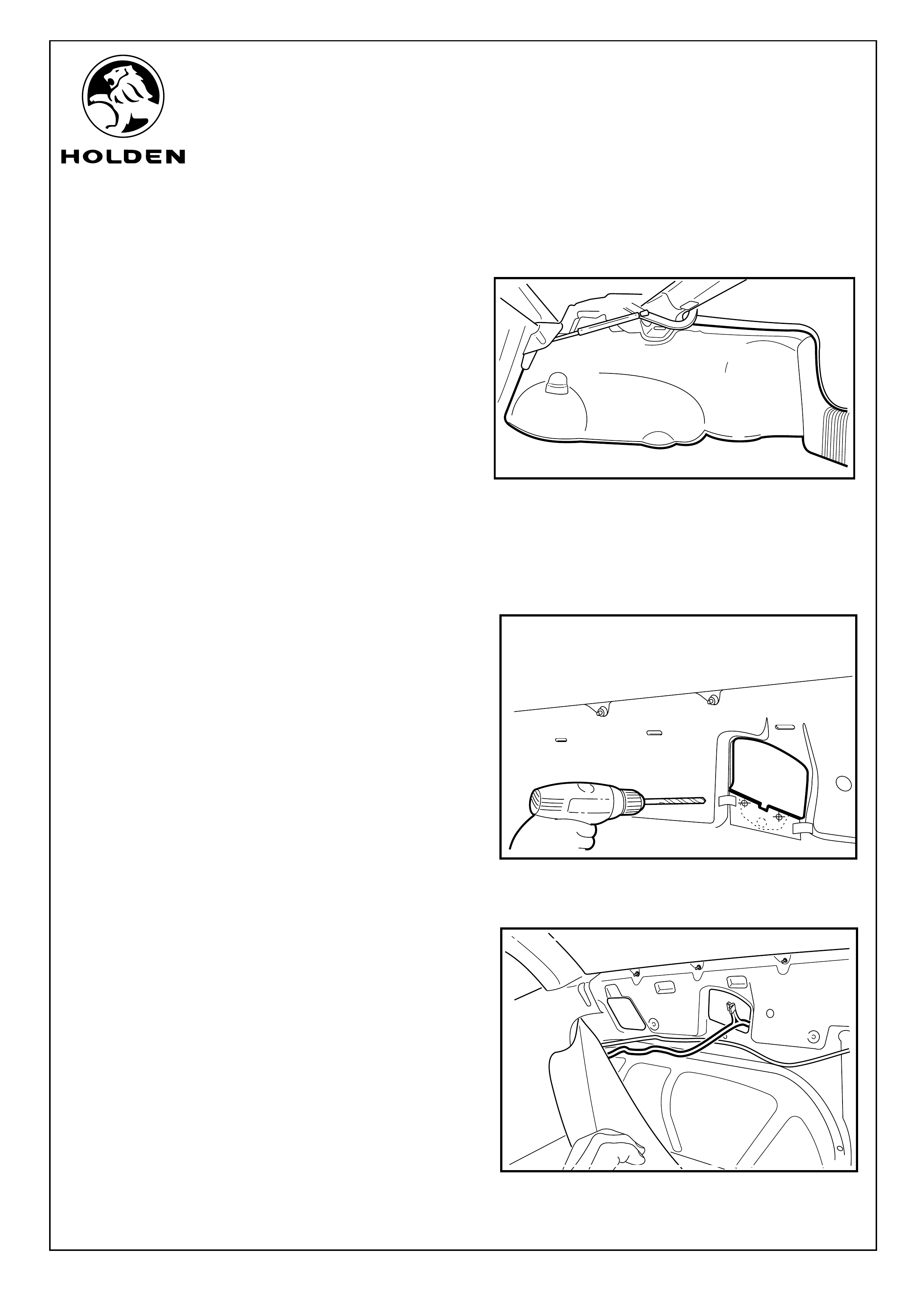
Refer to Figure 31 for the following:
47. Check the scale on the templates on the last pages of
this instructions. Use a pair of scissors to cut out the
template. Use the scriber to make the holes in the
template.
48. Align the template as indicated on the template and tape
into position.
49. Centre punch the hole positions.
50. Use a 5.5 mm diameter drill bit to drill the two mounting
holes for the bracket
51. Run the power outlet harness up and along the wheel
arch. Pass the power outlet harness into the rear quarter
panel cavity. Refer to Figure 32.
Page 12 of 15
FIGURE 30
FITTING INSTRUCTIONS FOR
REAR POWER OUTLET
FD1292
14SE04
COPYRIGHT
Reproduction in whole or part
prohibited without written approval
HOLDEN LTD
Division of HOLDEN Ltd ACN 006 893 232
FIGURE 33
FIGURE 34
FIGURE 35
200mm
FITTING INSTRUCTIONS: - continued...
Refer to Figure 33 for the following:
52. Run the power outlet harness inside the driver side rear
quarter panel towards the rear light assembly.
53. Rem
and remove.
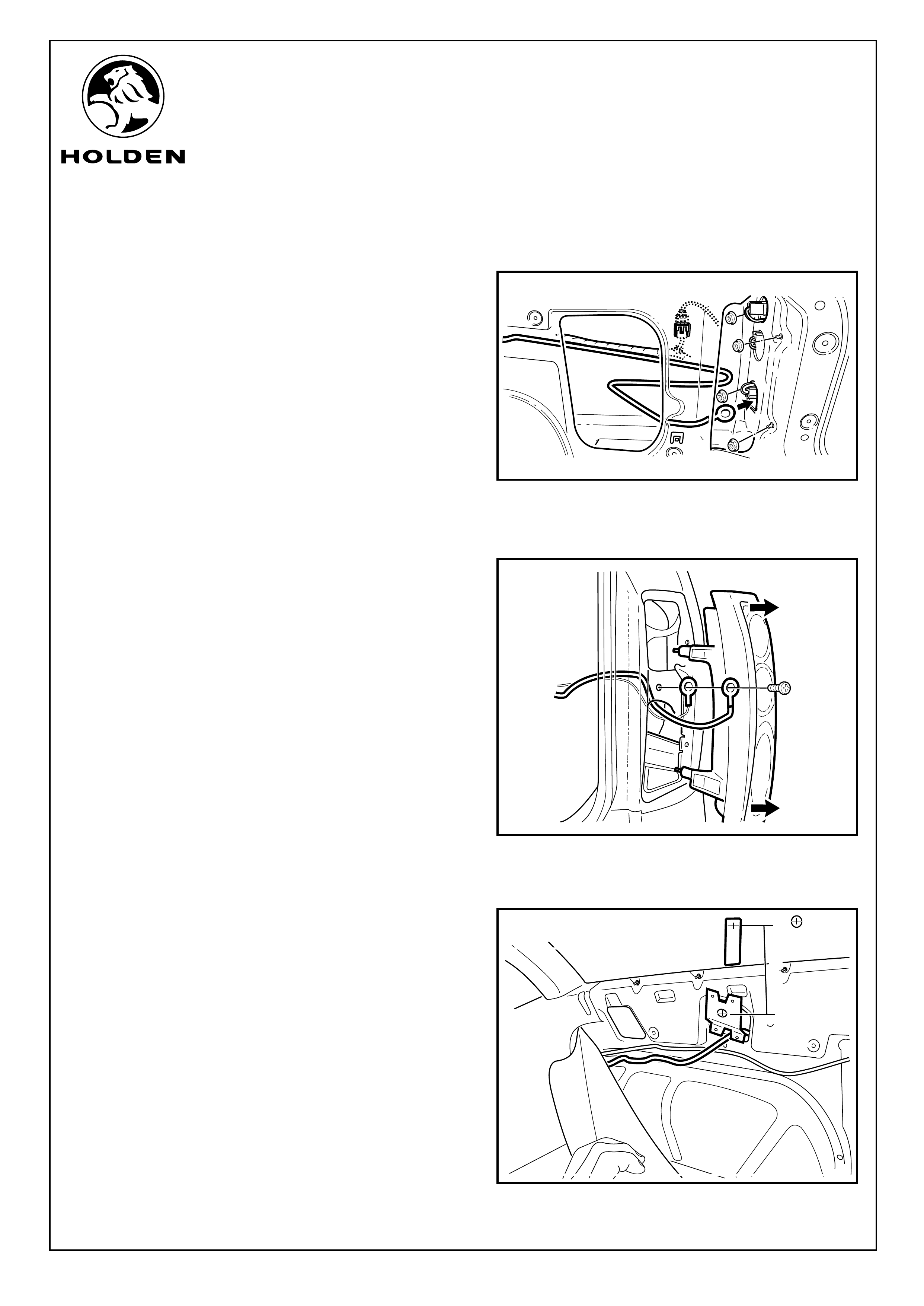
Refer to Figure 34 for the following:
54. Pass the black power outlet harness wire though the
lower light housing hole.
55. Remove the screw retaining the existing earth for the
rear light assembly. Use this screw to attach the power
outlet harness and the ground return for the rear light
assembly.
Refer to Figure 35 for the following:
56. Use nuts, bolts and washers (2 places) to attach the
power outlet bracket in the orientation shown to the rear
quarter panel.
57. Install some masking tape above the hole position on
the side window glass, mark a position that is 200mm
vertically above the centre of the large hole in the power
outlet bracket.
ove the nuts (4 places) retaining the driver side rear
light assembly
Page 13 of 15
3
FITTING INSTRUCTIONS FOR
REAR POWER OUTLET
FD1292
14SE04
COPYRIGHT
Reproduction in whole or part
prohibited without written approval
HOLDEN LTD
Division of HOLDEN Ltd ACN 006 893 232
FITTING INSTRUCTIONS: - continued...
Refer to Figure 36 for the following:
58. Temporarily refit the rear quarter panel carpet.
59. Measure 200mm vertically down from the mark on the
side glass and mark this position using a scriber.
60. Use a sharp knife to remove the carpet from within the
circle in the bracket, also remove the carpet from the
notch at the base of the circle.
61. Pull the rear quarter panel carpet out far enough to cut
away the carpet backing and to pass the power outlet
harness connector through the hole in the carpet.
62. Refit the rear quarter panel carpet.
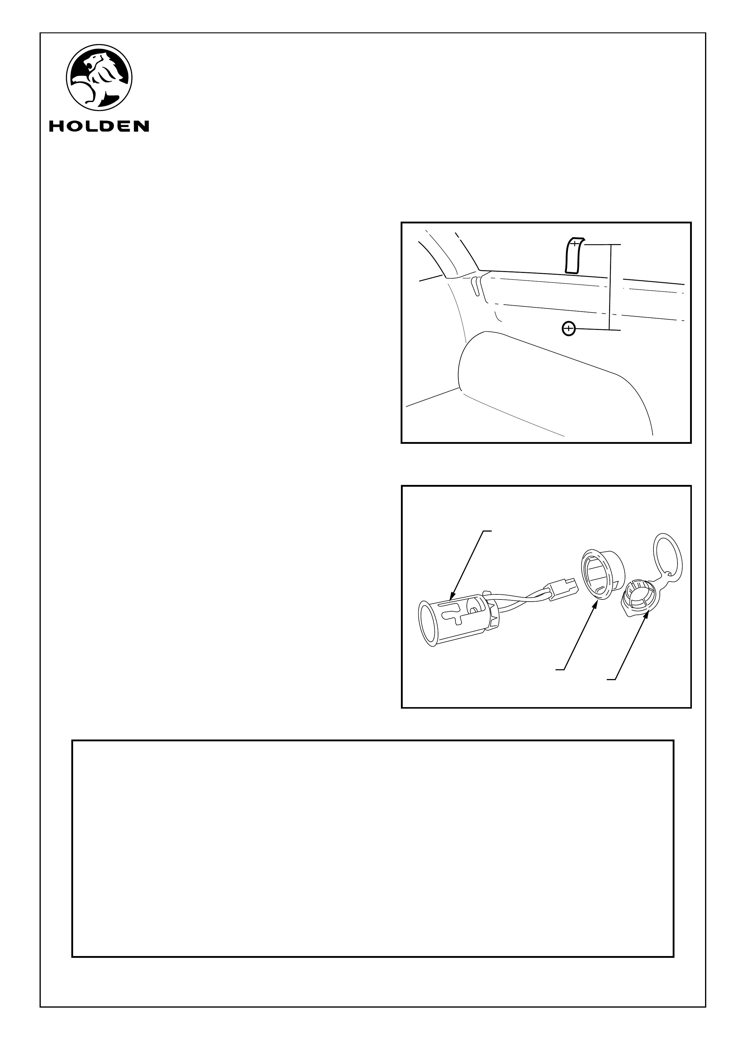
Sedan and Wagon
Refer to Figure 37 for the following:
63. Verify that battery voltage is present at the connector.
64. Install the power outlet cover (1) and bezel (2). Ensure
that the cover is rotated so that the hinged portion hangs
downwards.
65. Connect the wiring harness to the power outlet (3).
66. Install the power socket. The power socket should click
into position.
67. Refit all parts removed in reverse order.
69. Place the fitting instructions in the vehicle glovebox.
68. Insert the 10 Amp fuse supplied into position 25.
Page 14 of 15
200mm
FIGURE 36
FIGURE 37
PARTS LIST
PART NUMBER DESCRIPTION QUANTITY
92171326 REAR POWER OUTLET KIT 1
NS WIRING HARNESS 1
NS POWER OUTLET 1
NS MOUNTING BRACKET 1
SMALL PARTS KIT 1
NS BOLT - M5x16 2
FUSE - 10Amp 1
NS WASHER - FLAT 2
NS NUT - M5 NYLOC 2
NS CABLE TIES 15
FD1292 FITTING INSTRUCTIONS 1
FD796 PROOF OF WARRANTY CARD 1
21
3
FITTING INSTRUCTIONS FOR
REAR POWER OUTLET
FD1292
14SE04
COPYRIGHT
Reproduction in whole or part
prohibited without written approval
HOLDEN LTD
Division of HOLDEN Ltd ACN 006 893 232
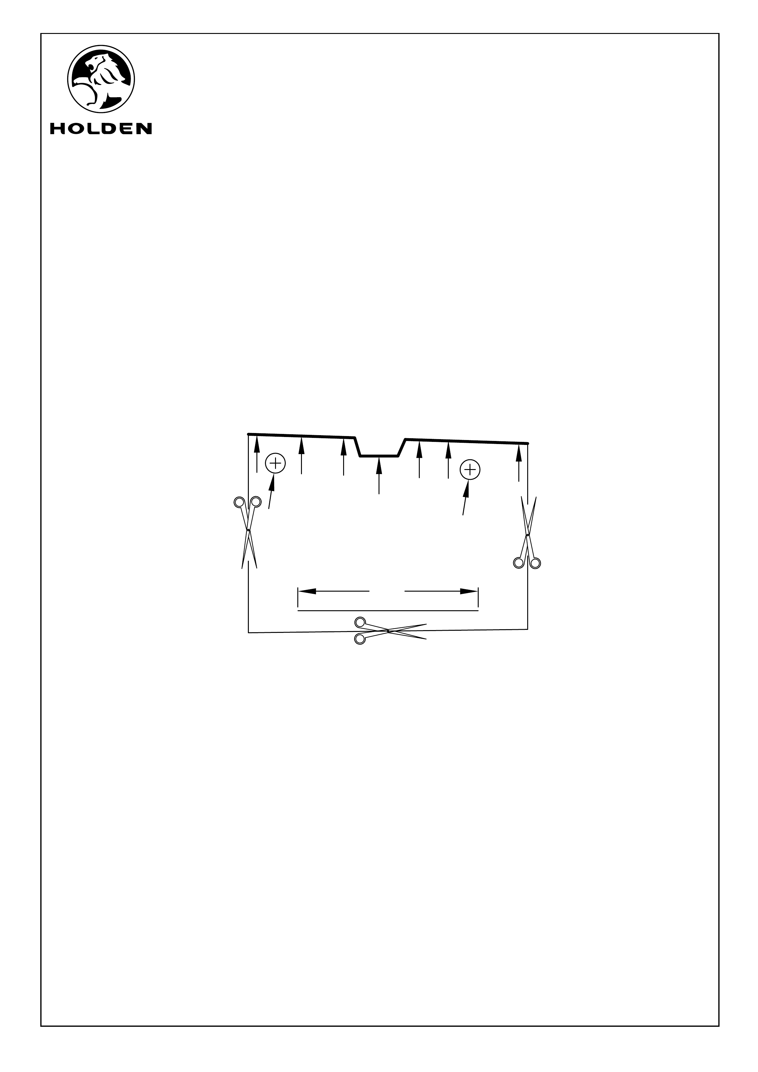
POWER OUTLET SUPPORT BRACKET TEMPLATE
IMPORTANT: ALWAYS CONFIRM
LENGTH OF 50MM SCALE
BEFORE DRILLING
5.5Æ
5.5Æ
50mm
Page 15 of 15