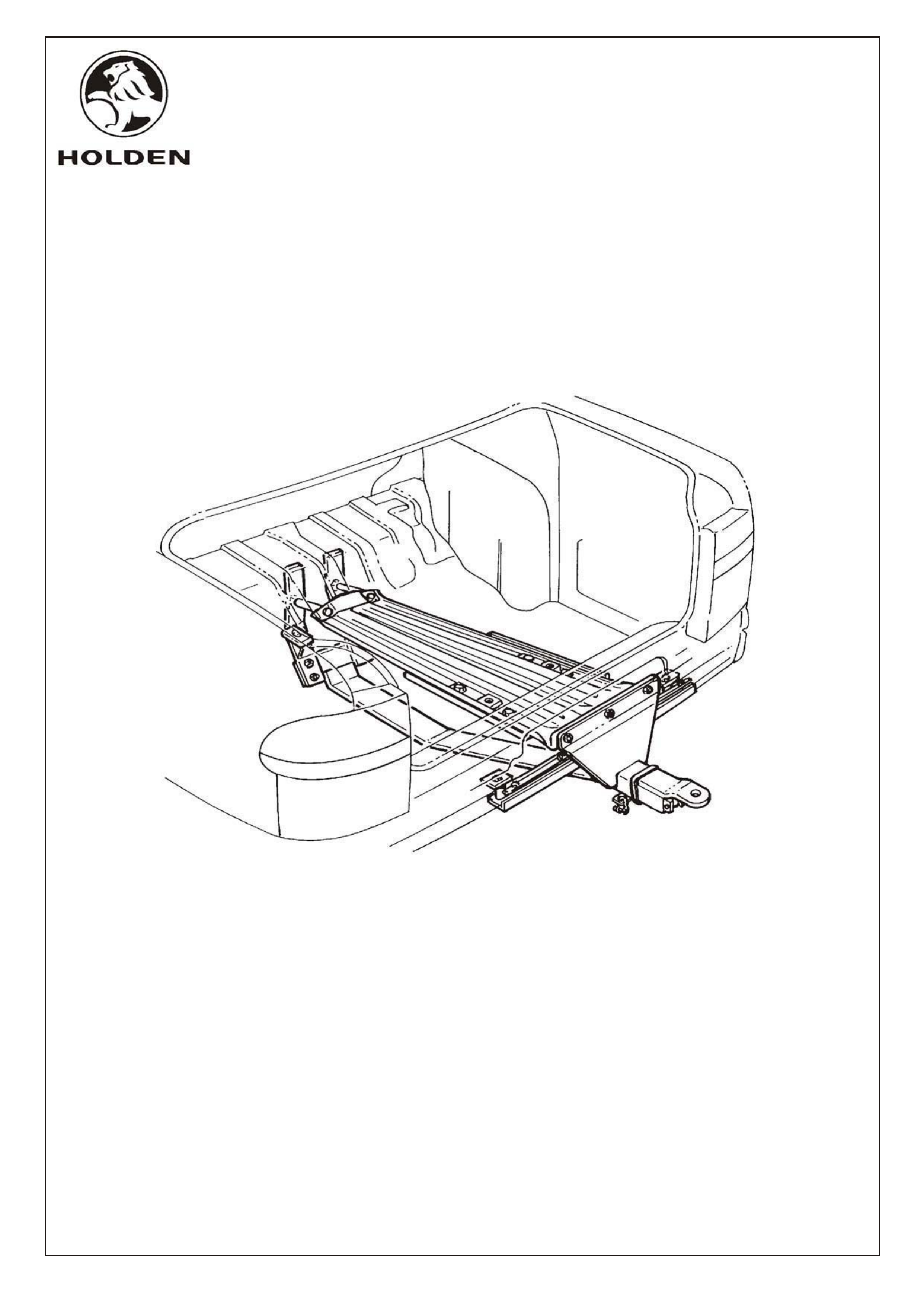
FITTING INSTRUCTIONS FOR
VS SEDAN (SWB & LWB) 2100 KG TOW BAR PACKAGE.
V6 & V8, INDEPENDENT REAR SUSPENSION &
AUTOMATIC TRANSMISSION
NOT INCLUDED IN TOW BAR PACKAGE, BUT MANDATORY TO FIT:
PACKAGE - SUPA LIFT SHOCK ABSORBERS
PACKAGE - POWER STEERING FLUID COOLER
PACKAGE - SEDAN REAR QUARTER BRACE (SWB ONLY)
PACKAGE - HEAVY DUTY EQUALISER HITCH
TOWING PATCH HARNESS (FLAT 7 PIN), or
TOWING PATCH HARNESS (ROUND 7 PIN)
HEAVY DUTY RADIATOR (V6 ONLY)
SYNTHETIC REAR AXLE OIL (V6 NON LSD ONLY)
OIL IDENTIFICATION TAG (V6 NON LSD ONLY)
Part number 92053227
92040363
92053149
M41155
M40742
92034465
M39838
92057296
HN2040
VS20590
M41536
M41535
PACKAGE - AUTO TRANS FLUID COOLER (V6), or
PACKAGE - AUTO TRANS FLUID COOLER (V8)
MANDATORY TO FIT FOR VS SERIES 1 ONLY,
IF EXTERNAL AUTO TRANS FLUID COOLER IS NOT ALREADY FITTED:
FD808
15JL99
COPYRIGHT
Page 1 of 12
FD808-1a
HOLDEN SERVICE PARTS OPERATIONS
Reproduction in whole or part
prohibited without written approval
Division of HOLDEN Ltd ACN 006 893 232
HSPO2-SH.CDR

Disconnect battery negative terminal.
Remove rear bumper bar, refer VS Service Manual Volume 1 Section 1D
Remove rear bumper support beam, refer Figure 3 view E and VS Service Manual Volume 1 Section 1D.
Position seam bracing plates 25mm each side of centre line of rear compartment, refer Figure 1 view A and
section A-A. Using bracing plates as templates, mark and drill six 8.5mm dia. holes.
Ensure surfaces to be coated are free from contaminants, oil and dirt. Apply metal primer, Dulux Epoxy
Primer Surfacer (DEPS) 410-39790 Black, or equivalent, then caulking compound, Dulux Fill And Seal
Putty, 409-19000 to any bare metal and around holes.(6 places).
Install seam bracing plate, retaining bolts, (M8 x 20mm, 6 off) washers and nuts and tighten to correct
Torque specification.
For ease of fitment it is essential the seam backing plates are located and secured before
fitment of the tow bar upper part assembly.
2100 KG TOW BAR FITTING INSTRUCTIONS (IRS)
SEAM BRACING PLATES
SEAM BRACING PLATE RETAINING NUT TORQUE SPECIFICATION 17 - 23Nm.
NOTE:
1.
2.
3.
4.
5.
6.
TOW BAR
WARNING: EXERCISE CARE WHEN DRILLING HOLES IN REAR COMPARTMENT FLOOR
IN VICINITY OF THE FUEL TANK.
NOTE:
NOTE:
Position the upper part assembly on the centre of the rear compartment floor, refer Figure 1. Mark rear
compartment floor where upper part assembly comes into contact with floor and remove deadener from
marked area of rear compartment floor, refer Figure 1.
Loosen fuel tank retaining strap rear retaining nut and bolt (DO NOT REMOVE) and slightly lower rear of fuel
tank to allow easier installation of tow bar.
Position 'U' channel strengthening plates and upper part assembly on centre line of rear compartment floor,
align holes in strengthening plates with those in upper part assembly.
It is essential that 'U' channel strengthening plate be located under the upper part assembly
when marking hole locations, to ensure correct height of bolt holes.
Using upper part assembly as a template mark the 9 retaining hole centres, refer Figure 1. Remove upper
part assembly.
Do not mark through welded nut on upper part assembly.
1.
2.
3.
4.
FD808
15JL99
COPYRIGHT
Page 2 of 12
FD808-2a
HOLDEN SERVICE PARTS OPERATIONS
Reproduction in whole or part
prohibited without written approval
Division of HOLDEN Ltd ACN 006 893 232
HSPO2-SH.CDR
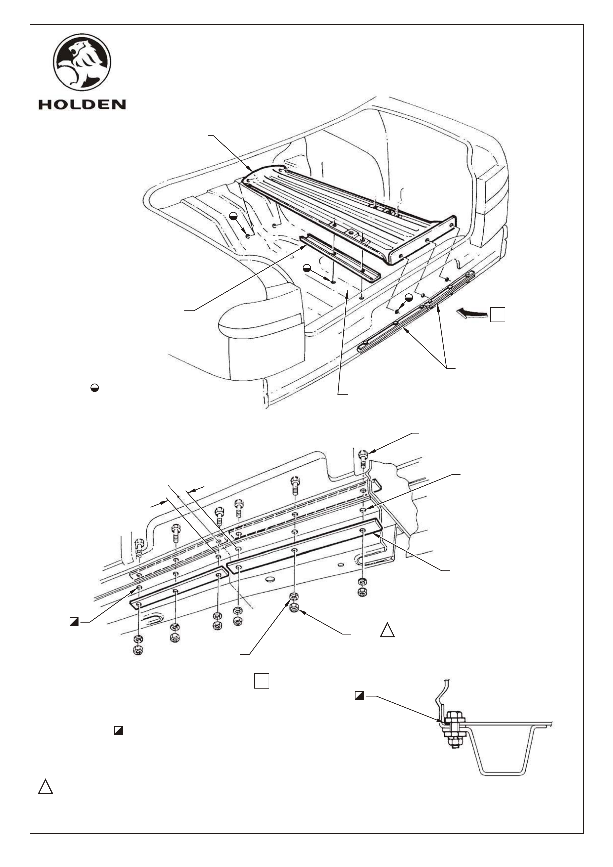
MARK HOLES 9 PLACES REMOVE DEADENER FROM
CONTACTING SURFACES OF
REAR FLOOR
SEAM BRACING PLATES
BOLT M8
(6 PLACES)
SEAM BRACING PLATE
(4 PLACES)
WASHER M8
(6 PLACES)
'U' CHANNEL
STRENGTHENING
PLATES
UPPER PART ASSEMBLY
A
A
VIEW
A-A
SECTION
11
NUT M8
(6 PLACES)
11
C
L25,0
25,0
17 - 23 Nm
ENSURE SURFACES TO BE COATED ARE FREE FROM CONTAMINENTS,OIL AND
DIRT. APPLY METAL PRIMER, DULUX EPOXY PRIMER SURFACER (DEPS)
410-39790 BLACK, OR EQUIVALENT AND ALLOW 10 - 15 MINUTES TO DRY, THEN
CAULKING COMPOUND, DULUX FILL AND SEAL PUTTY, 409-19000 TO ANY BARE
METAL AND AROUND HOLES.
(TYPICAL 6 PLACES)
DRILL 8,0 DIA.
+0,5
0,0
6 HOLES USING
BRACING PLATE
AS TEMPLATE
(6 PLACES)
(6 PLACES)
FD808
15JL99 Figure 1
COPYRIGHT
Page 3 of 12
FD808-3a
HOLDEN SERVICE PARTS OPERATIONS
Reproduction in whole or part
prohibited without written approval
Division of HOLDEN Ltd ACN 006 893 232
HSPO2-SH.CDR

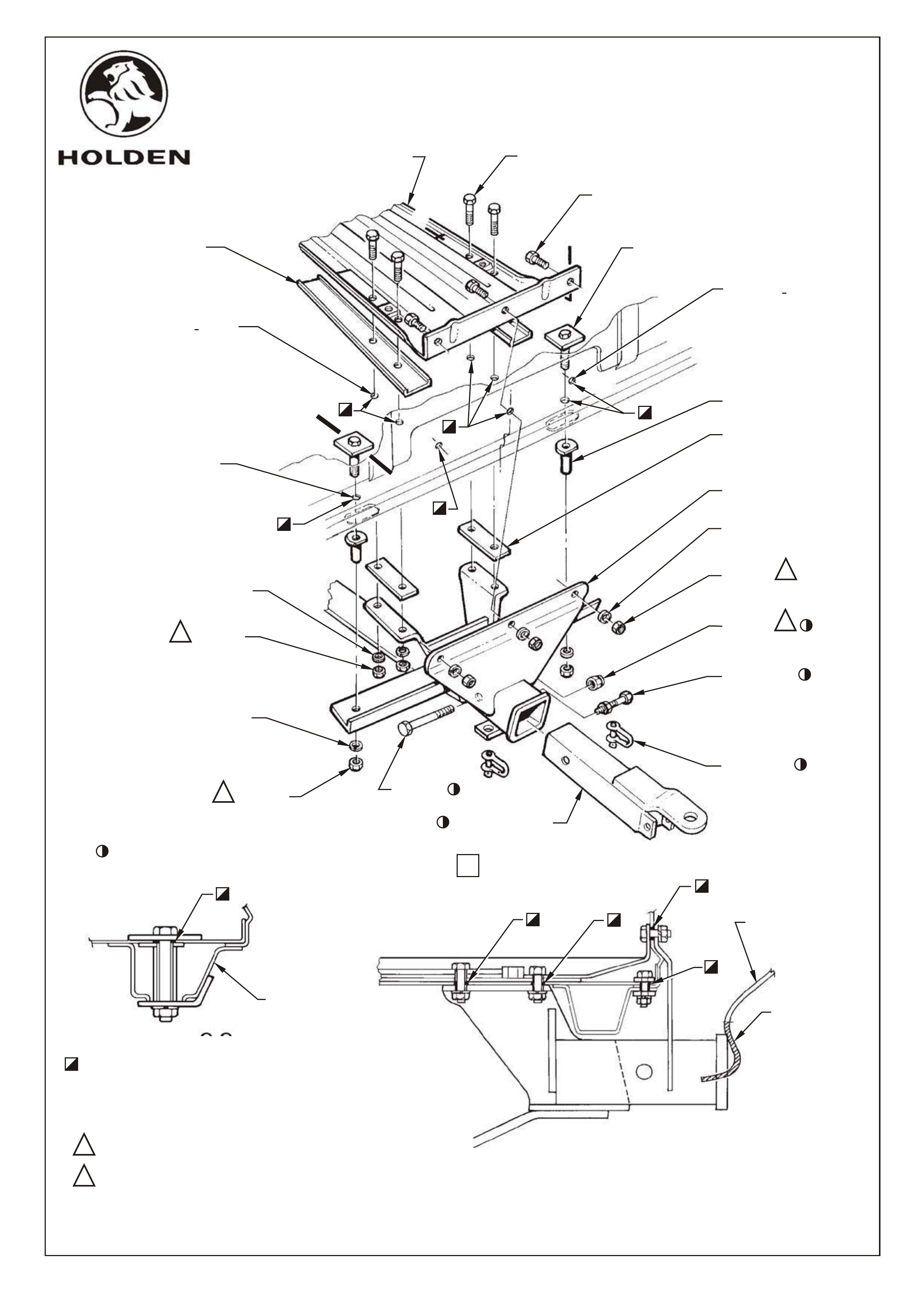
Drill four 12.5mm dia. holes in rear compartment floor, refer Figure 2 view B.
Drill three 12.5mm dia. holes in back panel lower, refer Figure 2 view B.
Drill two 12.5mm dia. holes in front of rear compartment floor, refer Figure 3 view C.
Ensure surfaces to be coated are free from contaminents, oil and dirt. Apply metal primer, Dulux Epoxy
Primer Surfacer (DEPS) 410-39790 Black, or equivalent and allow 10 - 15 minutes to dry, then caulking
compound, Dulux Fill and Seal Putty, 409-19000 to any bare metal and around holes,
(9 places), refer Figure 2 view B and Figure 3 view C.
Place 'U' channel strengthening plates and upper part assembly onto rear compartment floor.
Install bracket assembly through upper part assembly, 'U' channel and rear compartment floor.
Install spacers with welded washers into oval pressed holes in rear boxed section, refer Figure 2 section C-C.
Remove corresponding grommets from inside of rear compartment and remove deadener from area around
existing hole. Install the two bolts with welded washers (M10 x 80, 2 off), into existing holes in rear boxed
section and through spacers with welded washers, refer Figure 2 view B and section C-C.
Ensure surfaces to be coated are free from contaminents,oil and dirt. Apply metal primer, Dulux Epoxy
Primer Surfacer (DEPS) 410-39790 Black, or equivalent and allow 10 - 15 minutes to dry, then caulking
compound, Dulux Fill and Seal Putty, 409-19000 to any bare metal and around holes,
refer Figure 2 view B and section B-B, and section C-C.
Place nut with wire attached, wire end first through 19mm hole in crossmember outer panel at front of rear
floor. Pass wire through 10mm flared hole in lower face of crossmember, refer Figure 3 view D.
Install tow bar lower part assembly and retain by installing spring washers and nuts to bolts with square
plates, previously fitted (2 places).
Insert rear lower spacer plates between tow bar lower part assembly and underbody, refer Figure 2 view B.
From inside of rear compartment install upper part assembly to lower part assembly retaining bolts
(M10 x 35mm, 3 off) through the rear face of the lower part assembly, body and lower part assembly. From
outside of vehicle install spring washers and retaining nuts and hand tighten, refer Figure 2 view B and
section B-B.
Install upper part assembly to lower part assembly retaining bolts (M10 x 35mm, 4off) through upper part
assembly, rear compartment floor, 'U' channel strengthening plate, rear lower spacer plates and lower part
assembly, install spring washers and retaining nuts and hand tighten, refer Figure 2 view B and section B-B.
5.
6.
7.
8.
9.
10.
11.
12.
13.
14.
15.
16.
17.
18.
FD808
15JL99
COPYRIGHT
Page 4 of 12
FD808-4a
HOLDEN SERVICE PARTS OPERATIONS
Reproduction in whole or part
prohibited without written approval
Division of HOLDEN Ltd ACN 006 893 232
HSPO2-SH.CDR
C
B
B
C
B
VIEW
C-C
SECTION
B-B
A
SECTION
11
11
11
11
22
22
40 - 55Nm
70 - 90Nm
ENSURE SURFACES TO BE COATED ARE FREE FROM CONTAMINENTS,
OIL AND DIRT. APPLY METAL PRIMER, DULUX EPOXY PRIMER SURFACER
(DEPS), 410-39790 BLACK, OR EQUIVALENT AND ALLOW 10 - 15 MINUTES
TO DRY, THEN CAULKING COMPOUND, DULUX FILL AND SEAL PUTTY,
409-19000 TO ANY BARE METAL AND AROUND HOLES.
REAR BUMPER FACIA
REMOVE
REFER FIGURE 3
CROSSMEMBER-BACK
PANEL LOWER
UPPER PART
ASSEMBLY
BOLT M10
(4 PLACES)
BOLT M10
(3 PLACES)
'U' CHANNEL
STRENGTHENING
PLATE
(2 PLACES)
M10 BOLT-
WELDED PLATE
(2 PLACES)
SPACER
(2 PLACES)
REAR LOWER
SPACER PLATE
(2 PLACES)
LOWER PART
ASSEMBLY
WASHER M10
(3 PLACES)
NUT M10
(3 PLACES)
NUT M16
(NYLOC)
ANTI-RATTLE
BOLT ASSEMBLY
M10
'D' SHACKLE
(2 PLACES)
TOW BAR TONGUE
BOLT M16
NUT M10
(2 PLACES)
WASHER M10
(2 PLACES)
NUT M10
(4 PLACES)
WASHER M10
(4 PLACES)
EXISTING HOLE
DISCARD GROMMET
(2 PLACES)
PART OF TOW BAR TONGUE PACKAGE
4 HOLES IN REAR
FLOOR
CAUTION: EXERCISE
CARE WHEN DRILLING
IN VICINITY OF PETROL
TANK
3 HOLES IN BACK
PANEL LOWER
DRILL 12,0 DIA.
+0,5
0,0
DRILL 12,0 DIA.
+0,5
0,0
DETAIL
FD808
15JL99 Figure 2
COPYRIGHT
Page 5 of 12
FD808-5a
HOLDEN SERVICE PARTS OPERATIONS
Reproduction in whole or part
prohibited without written approval
Division of HOLDEN Ltd ACN 006 893 232
HSPO2-SH.CDR

Install lower part assembly to bracing strap retaining bolts(M12 x 35, 4 off), spring washers and nuts and
hand tighten, refer Figure 3 view C.
Initially tighten all bolts to 20Nm.
NOTE: This is important to ensure correct location of the bracing strap bolts.
Using bracing strap as template drill two 10mm dia. holes in crossmember, refer Figure 3 view C and
section D-D.
Locate bracing strap by placing M10 bolt with wire attached through inspection hole and fasten with spring
washer and nut, refer Figure 3 view C and section D-D.
Tighten all M10 bolts and nuts to correct torque specification (11 off).
M10 BOLT AND NUT TORQUE SPECIFICATION 40 - 55Nm.
Tighten all M12 bolts and nuts to the correct torque specification (4 off)
M12 BOLT AND NUT TORQUE SPECIFICATION 70 - 75Nm.
Tighten fuel tank strap retaining bolt and nut to the correct torque specification.
FUEL TANK STRAP RETAINING BOLT AND NUT TORQUE SPECIFICATION 15 - 25Nm.
Mark and cut rear bumper to allow reinstallation of rear bumper bar, refer Figure 3 Detail A.
Reinstall rear bumper support beam, refer Figure 3 view E and VS Service Manual Volume 1 Section 1D.
Reinstall rear bumper, refer VS Service Manual Volume 1 Section 1D.
Install tow bar tongue into tow bar assembly, install tow bar tongue retaining bolt flat washer and
nyloc nut. Install tow bar tongue anti rattle bolt (M10 x 35mm), spring washer and nut and tighten
to correct torque specification.
TOW BAR TONGUE RETAINING BOLT AND NUT TORQUE SPECIFICATION 80 - 90Nm.
TOW BAR TONGUE ANTI RATTLE BOLT AND NUT TORQUE SPECIFICATION 40 - 55Nm.
19.
20.
21.
22.
23.
24.
25.
26.
27.
28.
29.
FD808
15JL99
COPYRIGHT
Page 6 of 12
FD808-6a
HOLDEN SERVICE PARTS OPERATIONS
Reproduction in whole or part
prohibited without written approval
Division of HOLDEN Ltd ACN 006 893 232
HSPO2-SH.CDR
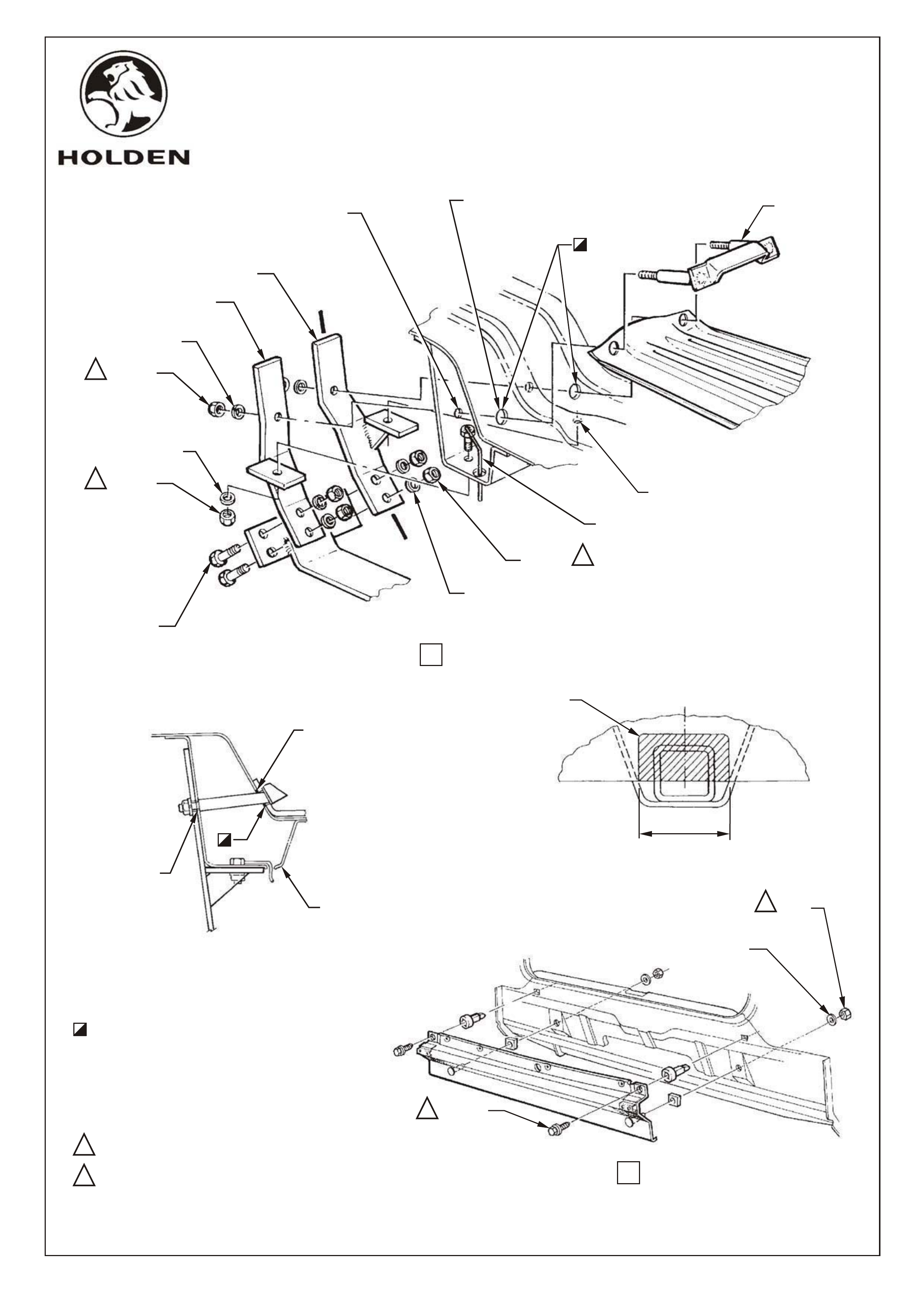
D
C
VIEW
BOLT M10
(2 PLACES)
BOLT M12
(4 PLACES)
NUT M10
(2 PLACES)
NUT M10
(2 PLACES)
WASHER M10
(2 PLACES)
WASHER M10
(2 PLACES)
NUT M12
(4 PLACES)
WASHER M12
(4 PLACES)
BRACKET
ASSEMBLY
11
11
11
22
70 - 75Nm
2240 - 55Nm
C
LOF VEHICLE
BEFORE INSTALLATION
OF TOW BAR, REMOVE
SHADED AREA SHOWN
FROM REAR BUMPER
FACIA
A
DETAIL
100
ENSURE SURFACES TO BE COATED ARE FREE FROM
CONTAMINENTS, OIL AND DIRT. APPLY METAL
PRIMER, DULUX EPOXY PRIMER SURFACER (DEPS)
410-39790 BLACK, OR EQUIVALENT AND ALLOW
10 - 15 MINUTES TO DRY, THEN CAULKING COMPOUND,
DULUX FILL AND SEAL PUTTY, 409-19000 TO ANY BARE
METAL AND AROUND HOLES.
DRILL 12,0 DIA. 2 HOLES
(ENLARGE TO 21,0 DIA. 2 HOLES)
+0,5
+0,5
-0,0
-0,0
DRILL 12,0 DIA. 2 HOLES
(ENLARGE EXISTING 8,0
DIA. HOLES)
DRILL 10,0 DIA.
2 HOLES IN REAR FLOOR
+0,5
-0,0
D
BRACING STRAP L.H.
BRACING STRAP R.H.
D-D
SECTION
REAR AXLE
CROSSMEMBER
ASSEMBLY
E
VIEW
11
22NUT
(2 PLACES)
WASHER
(2 PLACES)
SCREW
(2 PLACES)
+0,5
-0,0
21,0 DIA HOLE
+0,5
-0,0
21,0 DIA HOLE
FD808
15JL99 Figure 3
COPYRIGHT
Page 7 of 12
FD808-7a
HOLDEN SERVICE PARTS OPERATIONS
Reproduction in whole or part
prohibited without written approval
Division of HOLDEN Ltd ACN 006 893 232
HSPO2-SH.CDR

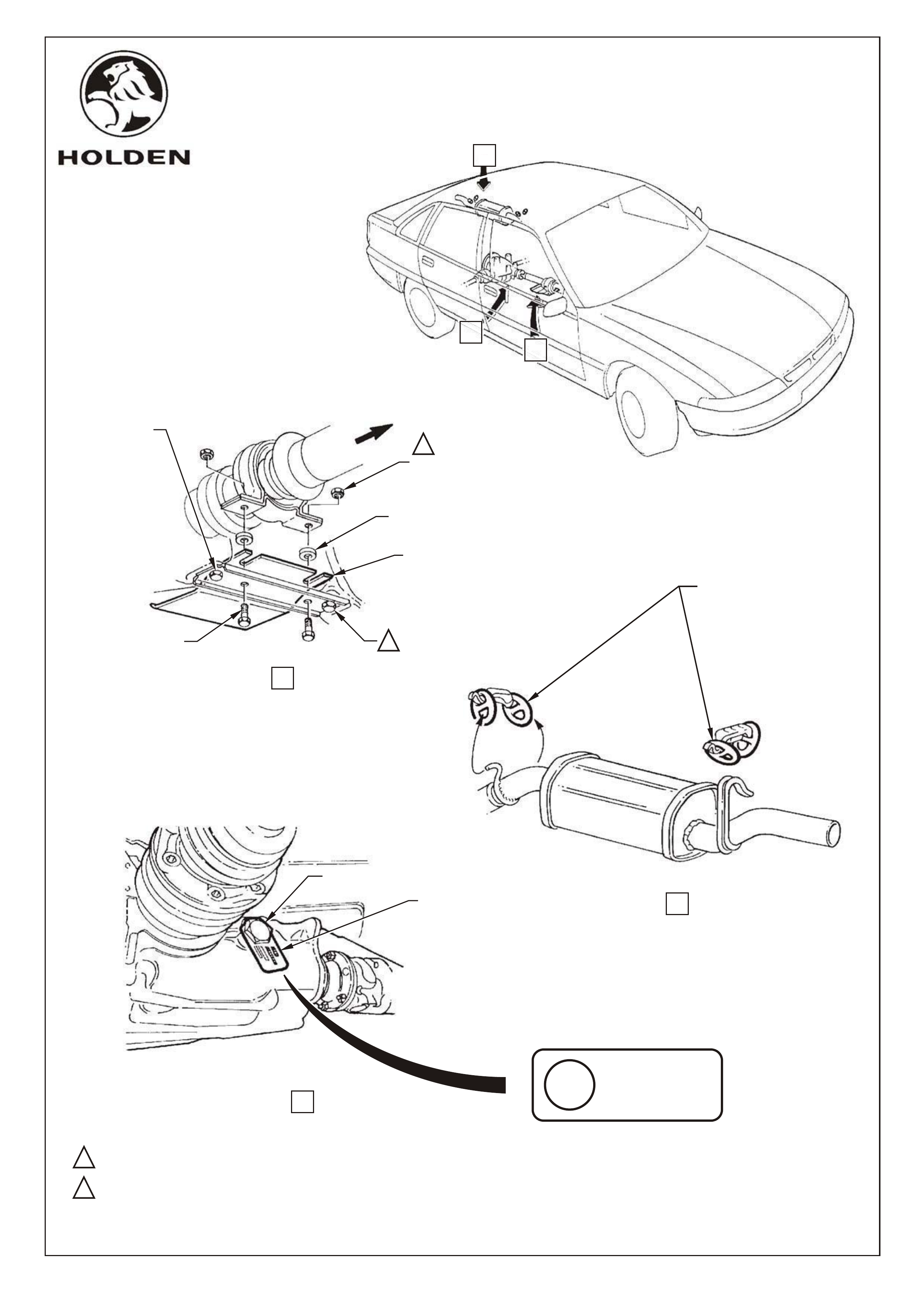
CENTRE BEARING HEAT SHIELD
Loosen centre bearing carrier to underbody retaining bolts, DO NOT REMOVE BOLTS.
Select correct heat shield: V6 - 92053241, or V8 - 92047132 (discard shield which is not required)
Slide centre bearing heat shield on top of centre bearing carrier and tighten to correct torque specification,
refer Figure 4 view A.
CENTRE BEARING TO LOWER CUP GUIDE
RETAINING BOLT TORQUE SPECIFICATION 20 - 25Nm
SILICONE EXHAUST SUPPORT RINGS
Remove and discard rear muffler support rings.
Install silicone support rings to rear muffler (2 places), refer Figure 4 view B.
REAR AXLE LUBRICANT CHANGE (V6 ONLY)
Due to high differential loads when towing 2100kg, it is essential that a synthetic (High Performance)
differential oil is used.
All V8 Commodores, and V6 Commodores with Limited Slip Differential (LSD) and or Anti Lock Braking
System (ABS), are supplied standard with synthetic oil. Differentials filled with synthetic oil may be easily
identified via a metal tag stating "HIGH PERFORMANCE, USE APPROVED LUBRICANT ONLY". Refer
Figure 4 view C.
For differentials not identified with this tag, a mineral based oil has been used. Before undertaking 2100kg
towing it is essential that the oil be changed to synthetic differential oil, Mobillube SHC, SAE 80W-140 (ID)
product code 51107 or equivalent to Holden's specification number HN2040. Refer to Owner's Manual
Volume No. 2 Section 4B1 for correct oil change procedure.
NOTE: Lowest retaining bolt on rear axle housing cover may be used for draining of oil.
Ensure that after the oil has been replaced, the axle is identified with the correct "HIGH PERFORMANCE,
USE APPROVED LUBRICANT ONLY" tag: P/No. VS20590. This will prevent incorrect oil being used during
service operations.
1.
2.
3.
1.
2.
1.
2.
3.
4.
FD808
15JL99
COPYRIGHT
Page 8 of 12
FD808-8a
HOLDEN SERVICE PARTS OPERATIONS
Reproduction in whole or part
prohibited without written approval
Division of HOLDEN Ltd ACN 006 893 232
HSPO2-SH.CDR
LOOSEN CENTRE BEARING
CARRIER BOLTS. RETIGHTEN
AFTER INSTALLATION OF
HEAT SHIELD
FRONT OF
VEHICLE
NUT - EXISTING
(2 PLACES)
SPACER - EXISTING
(2 PLACES)
BOLT - EXISTING
(2 PLACES)
HEAT SHIELD -
CENTRE BEARING
92053241 (V6)
92047132 (V8)
A
VIEW
11
22
HIGH
PERFORMANCE
USE APPROVED
LUBRICANT ONLY
REPLACE EXISTING
EXHAUST SUPPORT
RINGS WITH SILICONE
EXHAUST SUPPORT
RINGS
92049407
(4 PLACES)
C
VIEW
B
VIEW
11
22
OIL IDENTIFICATION
TAG
VS20590
FILLER PLUG
20 - 25Nm
20 - 35Nm
A
B
C
NOTE: WHERE OIL IDENTIFICATION TAG IS NOT FITTED,
DIFFERENTIAL OIL MUST BE CHANGED TO
SYNTHETIC DIFFERENTIAL OIL, MOBILLUBE SHC,
SAE 80W - 140 (ID) PRODUCT CODE 51107 OR
EQUIVALENT TO HN2040, THEN ATTACH OIL
IDENTIFICATION TAG VS20590.
FD808
15JL99 Figure 4
COPYRIGHT
Page 9 of 12
FD808-9a
HOLDEN SERVICE PARTS OPERATIONS
Reproduction in whole or part
prohibited without written approval
Division of HOLDEN Ltd ACN 006 893 232
HSPO2-SH.CDR
Remove backing from Owner's Manual sticker.
Place sticker on front cover of Owner's Manual.
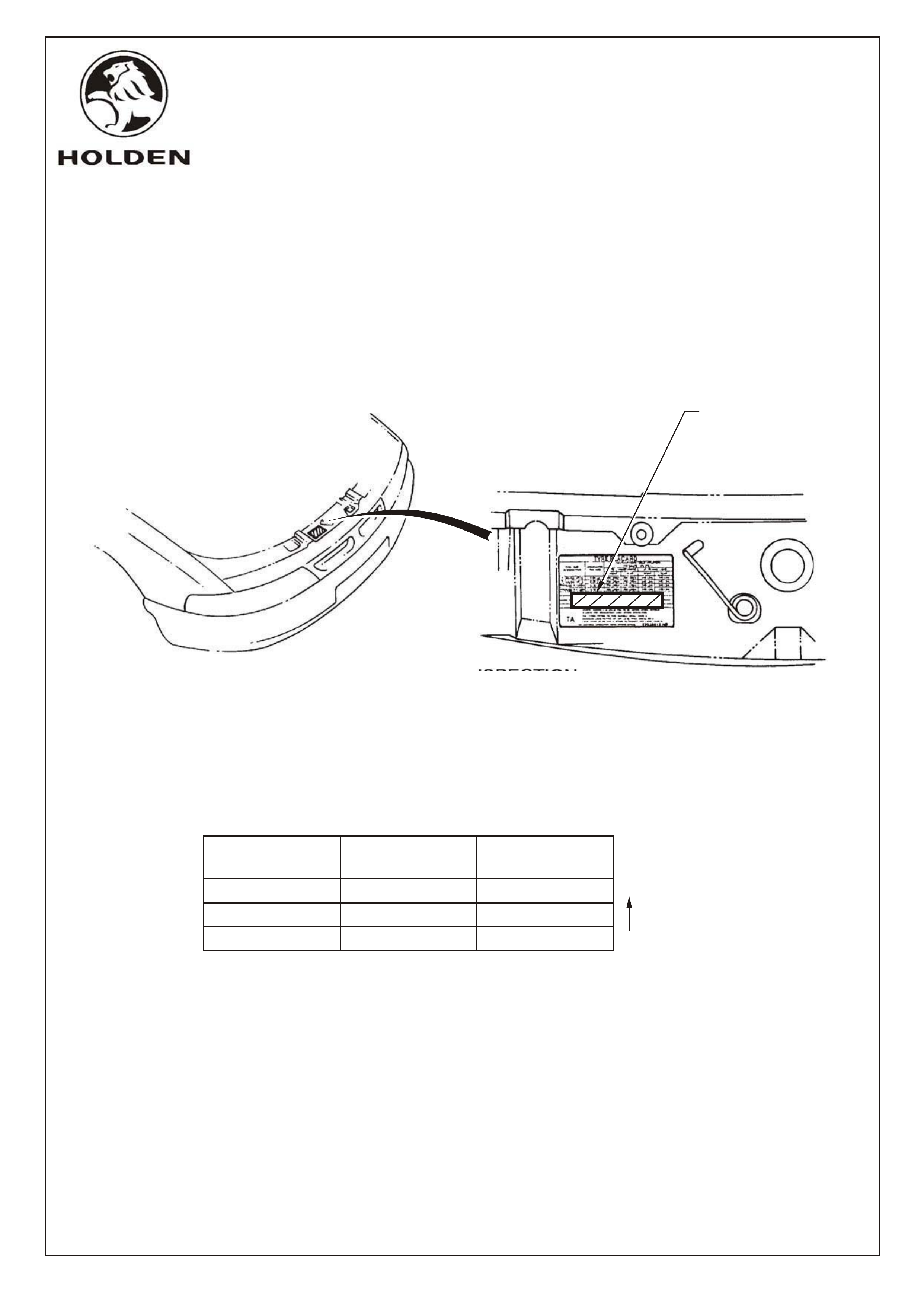
Open bonnet.
Remove backing from Tyre Placard sticker.
Place sticker in vacant area on original Tyre Placard.
NOTE: Do not cover any information on the original Tyre Placard.
Raise the front of vehicle, refer VS Service Manual Volume 1 Section 0A.
Remove front wheels, refer VS Service Manual Volume 5 Section 10.
NOTE : I nspect front and rear pads to ensure the same brake pad material is fitted front
and rear. Friction material markings are visible with wheels removed and calipers
still fitted to vehicle. The following materials may be used with this towing package
(in order of preference) :
If front brake pads differ from rear brake pads, replace whichever is least
preferred (refer chart) to match other pad type.
Remove front brake calipers, refer VS Service Manual Volume 2 Section 5A.
Remove front hub/brake discs, refer VS Service Manual Volume 2 Section 5A.
Remove front brake shields and discard, refer VS Service Manual Volume 12 Section 3.
Reinstall front hub/brake discs, refer VS Service Manual Volume 2 Section 5A.
Reinstall front calipers, refer VS Service Manual Volume 2 Section 5A.
Reinstall front wheels, refer VS Service Manual Volume 5 Section 10, and lower vehicle.
Reconnect battery negative terminal.
Most
Preferred
1.
2.
3.
1.
2.
3.
4.
5.
6.
7.
8.
9.
OWNER'S MANUAL STICKER
1.
2.
TYRE PLACARD STICKER
FRONT BRAKE SHIELD REMOVAL AND PAD INSPECTION
PLACE TYRE PLACARD
STICKER (M40752),
IN VACANT AREA ON
EXISTING TYRE
PLACARD STICKER.
Pad
Marking
Part No.
Front
Part No.
Rear
BM962 92055692 92055693
BMT6100 VS19504 VS19505
BM826 92046580 92046581
FD808
15JL99
COPYRIGHT
Page 10 of 12
FD808-10a
HOLDEN SERVICE PARTS OPERATIONS
Reproduction in whole or part
prohibited without written approval
Division of HOLDEN Ltd ACN 006 893 232
HSPO2-SH.CDR

NOT PART OF TOW BAR PACKAGE, BUT MANDATORY TO FIT *
SUPA LIFT SHOCK ABSORBERS *
AUTOMATIC TRANSMISSION COOLER *
(FOR VS SERIES 1 ONLY, IF AUTO TRANS FLUID COOLER IS NOT ALREADY FITTED)
Install supa lift shock absorbers in accordance with the fitting instructions contained in supa lift
shock absorber package.
Install automatic transmission cooler in accordance with the fitting instructions contained in
automatic transmission cooler package.
Install power steering cooler in accordance with the fitting instructions contained in the power
steering cooler package.
Install rear quarter panel brace in accordance with the fitting instructions contained in the rear
quarter brace package (SWB ONLY).
Install rear heavy duty equaliser hitch in accordance with the fitting instructions contained in the
heavy duty equaliser hitch package.
Install towing patch harness in accordance with the fitting instructions contained in towing patch
harness package.
Install heavy duty radiator in accordance with procedure outlined in VS Service Manual, Volume 1,
Section 6B1 (V6 only).
SUPA LIFT SHOCK ABSORBER PACKAGE
POWER STEERING COOLER *
REAR QUARTER BRACE *
HEAVY DUTY EQUALISER HITCH *
TOWING PATCH HARNESS *
HEAVY DUTY RADIATOR *
AUTOMATIC TRANSMISSION OIL COOLER PACKAGE (V6)
or
AUTOMATIC TRANSMISSION OIL COOLER PACKAGE (V8)
POWER STEERING COOLER PACKAGE
REAR QUARTER BRACE PACKAGE
HEAVY DUTY EQUALISER HITCH PACKAGE
TOWING PATCH HARNESS (FLAT 7 PIN)
or
TOWING PATCH HARNESS (ROUND 7 PIN)
HEAVY DUTY RADIATOR PACKAGE
92038038
M41536
M41535
92053149
M41155
M40742
92034465
M39838
92057296
FD808
15JL99
COPYRIGHT
Page 11 of 12
FD808-11a
HOLDEN SERVICE PARTS OPERATIONS
Reproduction in whole or part
prohibited without written approval
Division of HOLDEN Ltd ACN 006 893 232
HSPO2-SH.CDR

2100 KG TOW BAR PACKAGE FOR IRS (92053227)
PARTS LIST
PACKAGE - SUPA LIFT SHOCK ABSORBERS
PACKAGE - POWER STEERING FLUID COOLER
PACKAGE - SEDAN REAR QUARTER BRACE
PACKAGE - HEAVY DUTY EQUALISER HITCH
TOWING PATCH HARNESS (FLAT 7 PIN) or
TOWING PATCH HARNESS (ROUND 7 PIN)
HEAVY DUTY RADIATOR (V6 ONLY)
OIL IDENTIFICATION TAG (V6 ONLY)
SYNTHETIC REAR AXLE OIL, EG. MOBILLUBE SHC, SAE 80W - 140,
OR EQUIVALENT LUBRICANT TO HOLDEN'S SPECIFICATION HN2040 (V6 ONLY).
NOT INCLUDED IN TOW BAR PACKAGE, BUT MANDATORY TO FIT :
92040363
92053149
M41155
M40742
92034465
M39838
92057296
VS20590
HN2040
PART NO. DESCRIPTION QUANTITY
TOW BAR ASSEMBLY
CONSISTS OF:
UPPER PART ASSEMBLY
LOWER PART ASSEMBLY
BRACING STRAP RH
BRACING STRAP LH
'U' CHANNEL STRENGTHENING PLATE
BRACKET ASSEMBLY
NUT - M10
SPRING WASHER - 10mm
SPACER WITH WASHER -UPPER PART ASM. TO LOWER PART ASM.
BOLT - M10 x 80 WITH SQUARE PLATE
NUT - M10
SPRING WASHER - 10mm
PLATE - REAR LOWER SPACER
BOLT - M10 x 25mm
NUT - M10
SPRING WASHER - 10mm
BOLT - M10 x 35mm
NUT - M10
SPRING WASHER - 10mm
BOLT - M12 x 25mm
NUT - M12
SPRING WASHER - 12mm
BOLT - M10 x 30mm
SPRING WASHER - 10mm
SEAM BRACING PLATE
BOLT - M8 x 20mm
NUT - M8
SPRING WASHER - 8,0mm
TOW BAR TONGUE PACKAGE (CHROME)
CONSISTS OF:-
TOW BAR TONGUE
BOLT - M16 x 85mm
NUT - M16 (NYLOC)
FLAT WASHER 16mm
BOLT M10 x 35mm
NUT - M10mm
'D' SHACKLE
STRAP - ADJUSTABLE 120,0mm NYLON
STRAP - ADJUSTABLE 99,0 NYLON
SILICONE EXHAUST SUPPORT RING
BOOKLET - FITTING INSTRUCTIONS
CHART - 2100KG TOWING SYSTEMS
STICKER - TYRE PLACARD
STICKER - OWNER'S HANDBOOK
HEAT SHIELD - CENTRE BEARING(V6/V8, DISCARD SHIELD
WHICH IS NOT REQUIRED).
SP2776
SP3567
92049407
FD808
FD825
M40752
92053241/92047132
1
1
1
1
2
1
2
2
2
2
2
2
2
3
3
3
4
4
4
4
4
4
2
2
4
6
6
6
1
1
1
1
1
1
1
2
2
1
4
1
1
1
1
1/1
M40490
FD808
15JL99
COPYRIGHT
Page 12 of 12
FD808-12a
HOLDEN SERVICE PARTS OPERATIONS
Reproduction in whole or part
prohibited without written approval
Division of HOLDEN Ltd ACN 006 893 232
HSPO2-SH.CDR
M41536
M41535
PACKAGE - AUTO TRANS FLUID COOLER (V6) or
PACKAGE - AUTO TRANS FLUID COOLER (V8)
MANDATORY TO FIT FOR SERIES 1 ONLY,
IF EXTERNAL AUTO TRANS FLUID COOLER IS NOT ALREADY FITTED :