FD822
15JL98
COPYRIGHT
Page 1 of 1
FITTING INSTRUCTIONS FOR
OIL PAN SLEEVE SEALS
Part Number M41479
G90-2-1
HOLDEN SERVICE PARTS OPERATIONS
Reproduction in whole or part
prohibited without written approval
Division of HOLDEN Ltd ACN 006 893 232
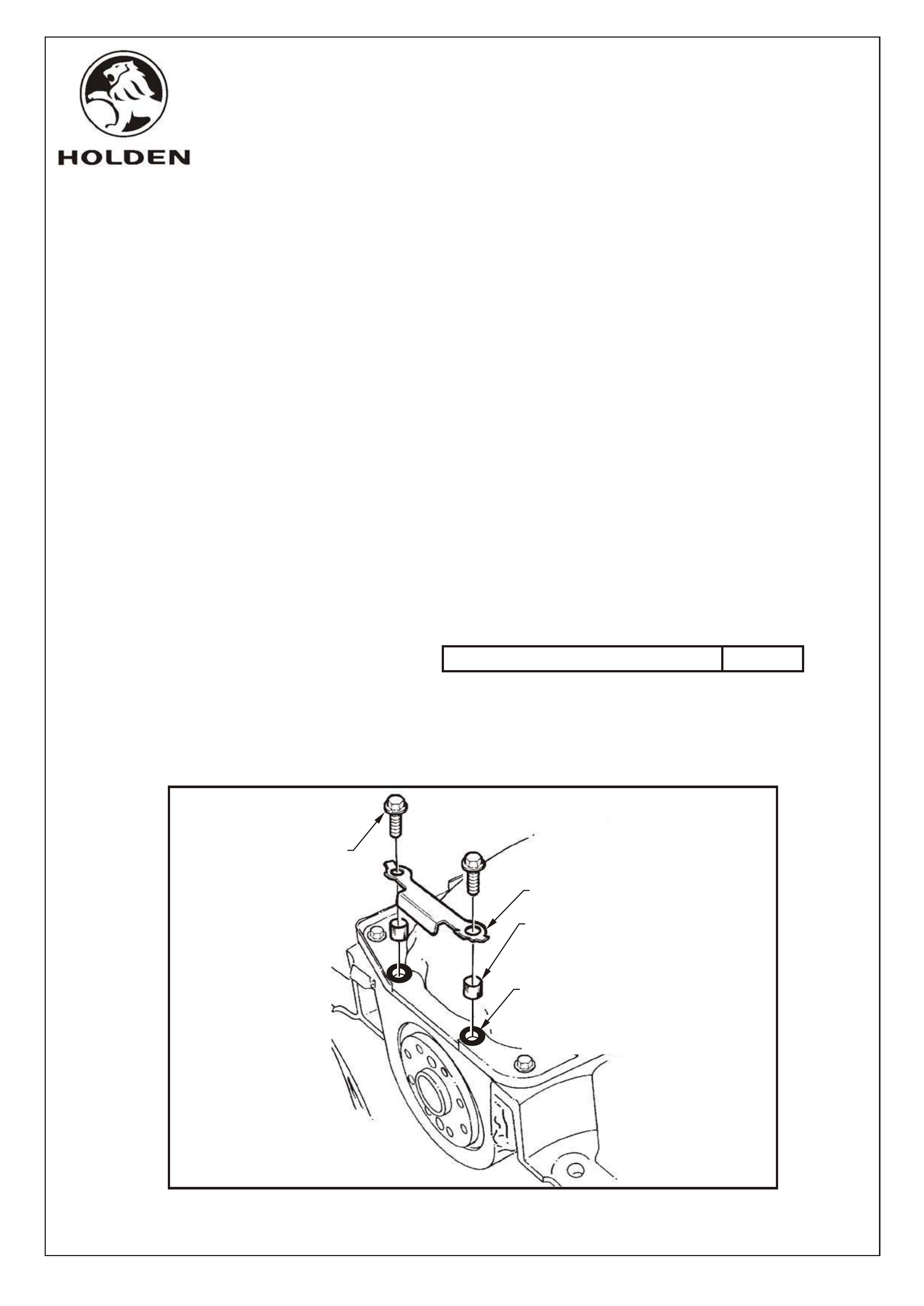
APPLY "LOCTITE 515"
TO THREADS AND
WASHER FACE OF SCREW
PRIOR TO INSTALLATION
LOCKING PLATE
APPLY "LOCTITE 515" TO THE
INSIDE OF THE TWO REAR
MOST OIL PAN SCREW HOLES
AND AROUND THE SCREW
HOLES AS SHOWN PRIOR TO
INSTALLATION OF SLEEVE
3122-08
PART NUMBER DESCRIPTION QUANTITY
92063593 SLEEVE - OIL PAN 2
24500866 GASKET - OIL PAN 1
INSTALLATION PROCEDURE:
1. Install oil pan as per Holden Dealer letter DL No. 59/96 VR V6 OIL LEAK RECTIFICATION PROCEDURE.
Refer section REINSTALL Procedures 1 to 6.
2. Carefully align the oil pan and the oil pan gasket with the two rear most oil pan bolt holes.
3. Apply Loctite 515 into and around the two rear most bolt holes.
4. Liberally apply Loctite 515 onto the inner and outer surfaces of the two rubber sleeves and carefully insert into the two rear most
bolt holes.
5. Place the lock plate into position.
6. Apply Loctite 515 on the thread and underside of the head of the two rear most oil pan bolts (yellow chromate coloured bolt) and
insert bolts into position (finger tight only)
7. Apply Loctite 515 to all remaining oil pan attaching bolt threads and insert them into position.
8. Tighten all oil pan bolts to the correct torque specification Oil pan attaching bolt/stud torque specification 8 - 12 Nm
IMPORTANT: The oil pan attaching bolts must be tightened to the correct tension. Overtightening will lead to gasket failure and
possible damage to oil pan dimples and/or front cover.
9. Bend lock plate tabs, align closest to flats on each bolt hex, over the two rear most oil pan bolt heads.
10. Refer to Procedure 15 to 17 of DL 59/96 for final installation procedures.
92063593
APPLY "LOCTITE 515"
TO SLEEVE PRIOR TO
INSTALLATION OF
SCREW AND LOCK PLATE