FITTING INSTRUCTIONS FOR
VT - VY COMMODORE WAGON 3RD SEAT PACKAGE
Part No. 92043234
FD840
25OC02
COPYRIGHT
Page 1 of 8
G727
HOLDEN SERVICE PARTS OPERATIONS
Reproduction in whole or part
prohibited without written approval
Division of HOLDEN Ltd ACN 006 893 232
IMPORTANT: 3RD SEAT PACKAGE MUST NOT BE INSTALLED
TO VEHICLES FITTED WITH LPG PACKAGE
1. Remove fir tree fasteners (two places) from carpet and spare wheel cover assembly, directly behind rear seat
back, using wide blade screw driver or claw hammer.
2. Remove carpet and spare wheel cover assembly from vehicle. Remove cargo space rear plastic trim.
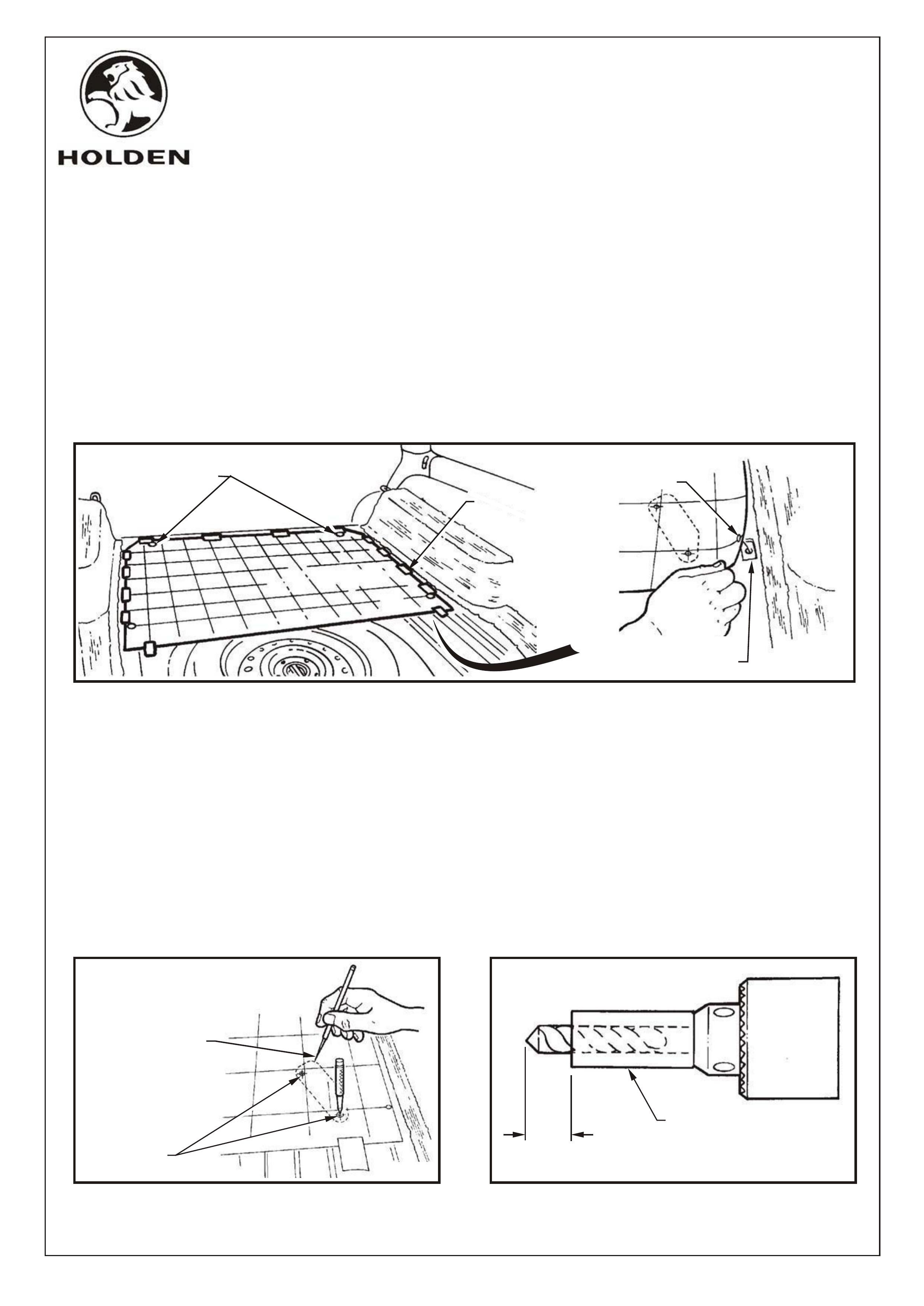
3. Locate film template to rear compartment floor aligning two large holes behind rear seat with two marked holes on
template, refer figure 1. Slit template at mark on left side to allow template under moulded carpet.
4. Using the template as a guide, locate rear datum holes in floor which are covered with heat fusible deadener.
Using a heat gun to soften deadener, remove deadener from these areas to expose datum holes (1 each side),
refer figure 1.
5. Accurately align 4 datum holes in floor with holes marked on template(some approximation may be required due
to slight differences in floor panels). Securely tape template to floor every 300mm around perimeter, refer figure 1.
ALIGN TEMPLATE OVER
FRONT LOCATING HOLES
FIGURE 1
USE TEMPLATE TO
FIND GENERAL AREA
OF LOCATING HOLE
TAPE EDGE
EVERY 300mm
SCRAPE DEADENER AWAY
TO EXPOSE LOCATING HOLE
(RH SHOWN, LH OPPOSITE)
CENTRE PUNCH
MOUNT HOLE
LOCATIONS
25,0
MAX
SPACER
(USE SNUG FITTING HOSE
OR SIMILAR)
NOTE: Take care not to move or dislodge template whilst marking hole centres or deadener removal locations.
Do not lean on template.
6. Centre punch mount hole locations through template onto floor (8 places), refer figure 2.
7. Use a scribe to dot a guideline through the template, onto the floor at each pivot mount and striker location, to
outline area requiring deadener removal, (guidelines are marked on template). Refer figure 2.
8. Remove template and drill 3.0mm dia pilot holes for mounting bolts (8 places).
IMPORTANT: RH striker mount is located directly over fuel tank so to prevent puncturing tank the following procedure
must be adhered to:
When drilling RH striker mount holes a spacer must be used over the drill bit to ensure 25mm maximum of drill tip
will protrude through drilled surface, refer figure 3.
FIGURE 3FIGURE 2
USE A SCRIBE TO DOT
A LINE THROUGH THE
TEMPLATE, ONTO THE
FLOOR, TO OUTLINE
AREA REQUIRING
DEADENER REMOVAL
COPYRIGHT
Page 2 of 8
HOLDEN SERVICE PARTS OPERATIONS
Reproduction in whole or part
prohibited without written approval
Division of HOLDEN Ltd ACN 006 893 232
FD840
25OC02
G727

9. Drill 10.5mm dia holes at LH striker front hole
location, (right through floor, rear longitudinal, and
rear muffler heat shield). Enlarge hole through floor
only to 19mm dia., refer figures 5 and 6. Use a spacer
on the drill bit to achieve 100-110mm drill tip depth to
avoid drilling hole in muffler,(similar to figure 3).
10. Drill 8.5mm dia. holes through floor at other 3 striker
mount locations.
11. Drill 10.5mm dia holes through floor at front pivot
mount locations (4 places), refer figure 6.
12. Cut deadener along dotted lines marked at mount
locations. Use a heat gun to soften deadener then
scrape deadener from these areas (4 places), refer
figure 4.
13. Vacuum swarf and removed deadener from floor or
use a magnet to collect swarf.
NOTE: Coat any bare metal which may have been
exposed during removal of deadener, with anti-corrosion
primer. Apply caulking compound to plates and washers
under car.
14. Install the 4 mount brackets and 8 bolts through the
floor at appropriate locations, refer figure 6.
FIGURE 4
CUT AND SCRAPE
DEADENER FROM
PREVIOUSLY
MARKED AREA
WASHER
M10
'NYLOC'
NUT
REAR
LONGITUDINAL
REAR
COMPARTMENT
FLOOR
REAR
MUFFLER
HEAT SHIELD
LH STRIKER
M10 BOLT
A-A
SECTION (REFER FIGURE 6)
(INSTALLED CONDITION) FIGURE 5
M8 BOLT
(4 PLACES)
DRILL 8.5
DIA HOLES
(2 PLACES)
DRILL 8.5
DIA HOLES
(4 PLACES)
DRILL 8.5
DIA HOLE
NUT PLATE
NUT PLATE
NUT PLATE
M10 "NYLOC" NUT
NUT PLATE
LH PIVOT
MOUNT
M10 BOLT
M8 BOLT
LH STRIKER
RH STRIKER
22Nm
44Nm
DRILL 19.0
DIA HOLE
THRU FLOOR
ONLY
SPRING WASHER
(4 PLACES)
DRILL 10.5 DIA
THRU REAR LONGITUDINAL
A
A
1
M8 BOLT
(2 PLACES)
1
1
2
2
FIGURE 6
WASHER
SPRING WASHER
(4 PLACES)
COAT BARE METAL
WITH ANTI - CORROSION
PRIMER AND APPLY CAULKING
COMPOUND AROUND HOLES
COPYRIGHT
Page 3 of 8
HOLDEN SERVICE PARTS OPERATIONS
Reproduction in whole or part
prohibited without written approval
Division of HOLDEN Ltd ACN 006 893 232
FD840
25OC02
G727
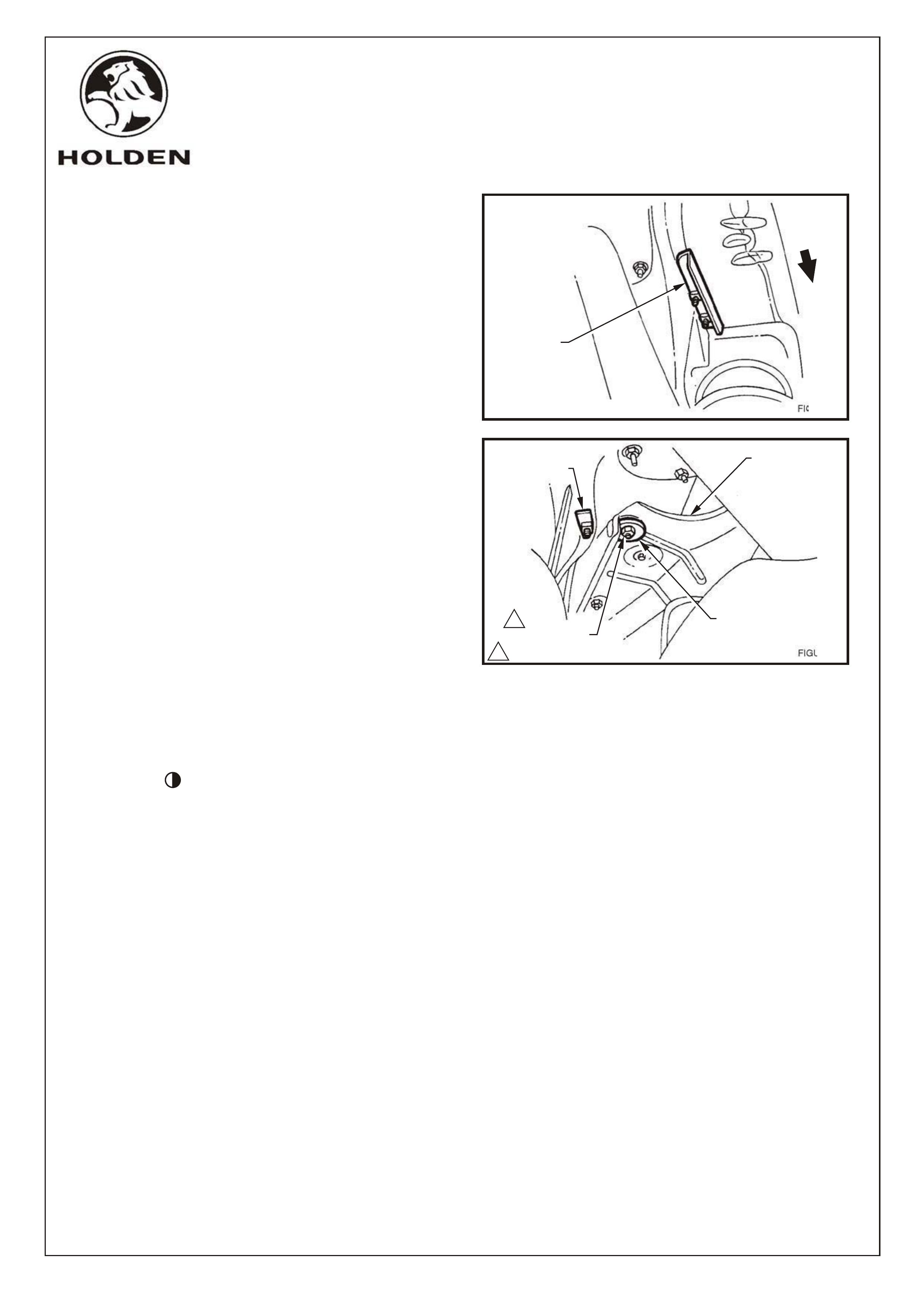
FIGURE 7
FIGURE 8
15. Raise vehicle, remove rear muffler support rubbers (2
places) and allow exhaust to hang.
NOTE: For V8 and supercharged V6 vehicles, remove 3
most LH support rubbers from intermediate muffler
assembly. Allow exhaust to hang on RH outboard bumper
rubber and support mufflers with tall jack e.g.
transmission jack.
16. Offer front pivot mounting nut plates (2 places) up to
bolts, refer figure 7, and hand tighten bolts from inside
the rear compartment.
17. Offer LH striker mounting nut plate up to rear most bolt
and hand tighten bolt from inside rear compartment.
18. Install large washer and "Nyloc" nut to bolt protruding
through heat shield. Tighten bolt from inside rear
compartment until rib in heat shield is crushed flat.
Tighten nut to 44 Nm, refer figure 8.
19. Install RH striker mounting nut plate to bolts. Hand
tighten bolts, refer figure 6.
NOTE: Use angled handle on RH rear weld nut plate to
install plate into position above fuel tank. Use M8 x 45 bolt
(pivot bolt) to catch one of the holes in the RH nutplate to
locate it. Fit M8 x 30 bolt to the other hole and tighten.
Replace M8 x 45 bolt with M8 x 30 bolt and tighten.
20. Turn template over so it is upside down.
21. Cutout from template the continuous outlines
(marked, ) at floor mounts and keep cut-outs. Cut
out small circles marked "underfelt points" and those
marked "Under-carpet alignment holes"
22. Align with holes in masonite and with visible scribe
marks on underside of wheel cover.
23. Carefully mark underfelt on wheel cover with a marker
through the "underfelt holes" perforated in the
template. Carefully remove template.
24. Join up points on underfelt as shown on template, cut
away felt and remove. Scrape revealed surfaces
clean, ensuring not to remove scribe lines.
25. Accurately replace template to wheel cover.
26. Mark on plastic and masonite around the perimeter of
cutout mounting holes in template.
27. Remove template.
INSTALL
NUT PLATE
WITH FLANGE
ON ANGLE,
OUTBOARD
FRONT
RH SHOWN, LH SIMILAR
REAR MUFFLER
HEAT SHIELD
WASHER
NYLOC NUT M10
(44Nm TORQUE)
NUT PLATE
1
1
COPYRIGHT
Page 4 of 8
HOLDEN SERVICE PARTS OPERATIONS
Reproduction in whole or part
prohibited without written approval
Division of HOLDEN Ltd ACN 006 893 232
FD840
25OC02
G727
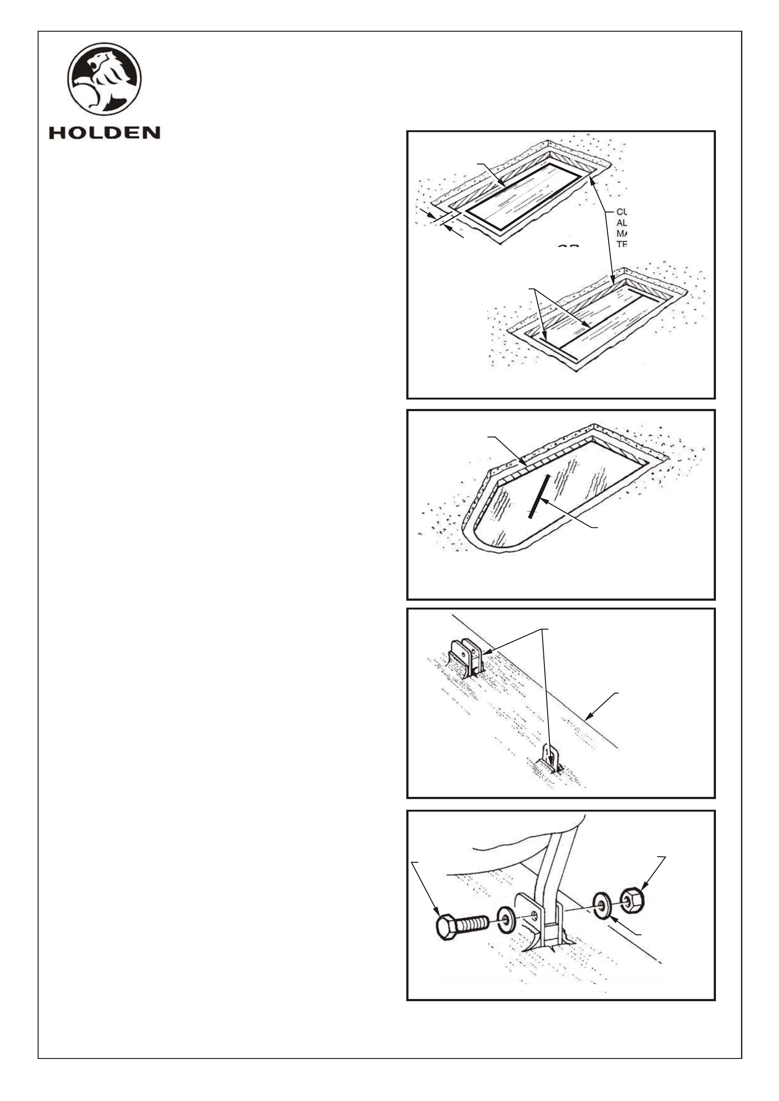
FIGURE 11
ALIGN SLOTS IN CARPET
OVER PIVOT MOUNTS
AND STRIKERS
REFIT CARPET
AND SPARE WHEEL
COVER ASSEMBLY
FIGURE 12
NYLOC
NUT M8
FLAT WASHER
BOLT M8
RH SHOWN, LH OPPOSITE
28. Use a short 3.0dia. drill. Drilling depth must be limited
to 4.0 +0.0 -0.75mm to prevent drilling through carpet.
Use an appropriate length of copper tube slipped over
and crimped to the drill bit (up to the chuck), for a
spacer.
29. Drill at 4-5mm intervals around perimeter of marks.
Ensure the drill does not go through the carpet.
30. Use a blunt chisel, 12mm wide, to crack plastic all
around perimeter. DO NOT CUT THROUGH
CARPET. Remove plastic cut-out.
NOTE: The plastic is glued to the carpet.
31. Insert chisel or srewdriver under one edge of the
perforated cut-out in the masonite and lever piece out.
Clean up edge of hole.
NOTE: The masonite is glued to the carpet.
32. Place rear striker cut-out pieces of template in the
holes appropriate to them. Approximation may be
required , depending on accuracy of hole.
33. Use a chisel on a block of wood to cut through the
carpet in the places indicated on the template.
FIGURE 10
SLIT CARPET
HERE FOR
STRIKER LOOP
RH STRIKER CUTOUT SHOWN,
LH SIMILAR
CUT PLASTIC ALONG
MARKED LINE
FIGURE 9
SLIT CARPET
HERE
CUT MASONITE
ALONG LINE
MARKED OFF
TEMPLATE
OR
CUT OUT
SECTION
OF CARPET
CUTOUT FOR FRONT PIVOT MOUNTS
5.0mm
NOTE: One of two methods may be used to trim carpet
around front pivot mounts. If method 34a. is used a hole
will be left in floor carpet if 3rd seat is ever removed,
whereas with method 34b. the carpet flaps will lie back
down to fill the hole.
34a.Trim carpet 5mm inside perimeter of hole cut in
masonite, refer figure 9.
OR
34b.Slit carpet along centre of hole in masonite and
across each end of hole, refer figure 9.
NOTE: A short slit in the carpet(as indicated on the
template), is all that is required at rear striker locations, to
allow striker loop to protrude through carpet, refer figure
10.
35. Refit carpet and spare wheel cover assembly to rear
compartment over 3rd seat pivot and striker mounts,
refer figure 11. Replace fir tree fasteners.
36. Install 3rd seat front leg mounts and install bolts.
Attach washers and "Nyloc" nuts (2 places), refer
figure 12.
NOTE: Do not over tighten leg mount nuts.
COPYRIGHT
Page 5 of 8
HOLDEN SERVICE PARTS OPERATIONS
Reproduction in whole or part
prohibited without written approval
Division of HOLDEN Ltd ACN 006 893 232
FD840
25OC02
G727
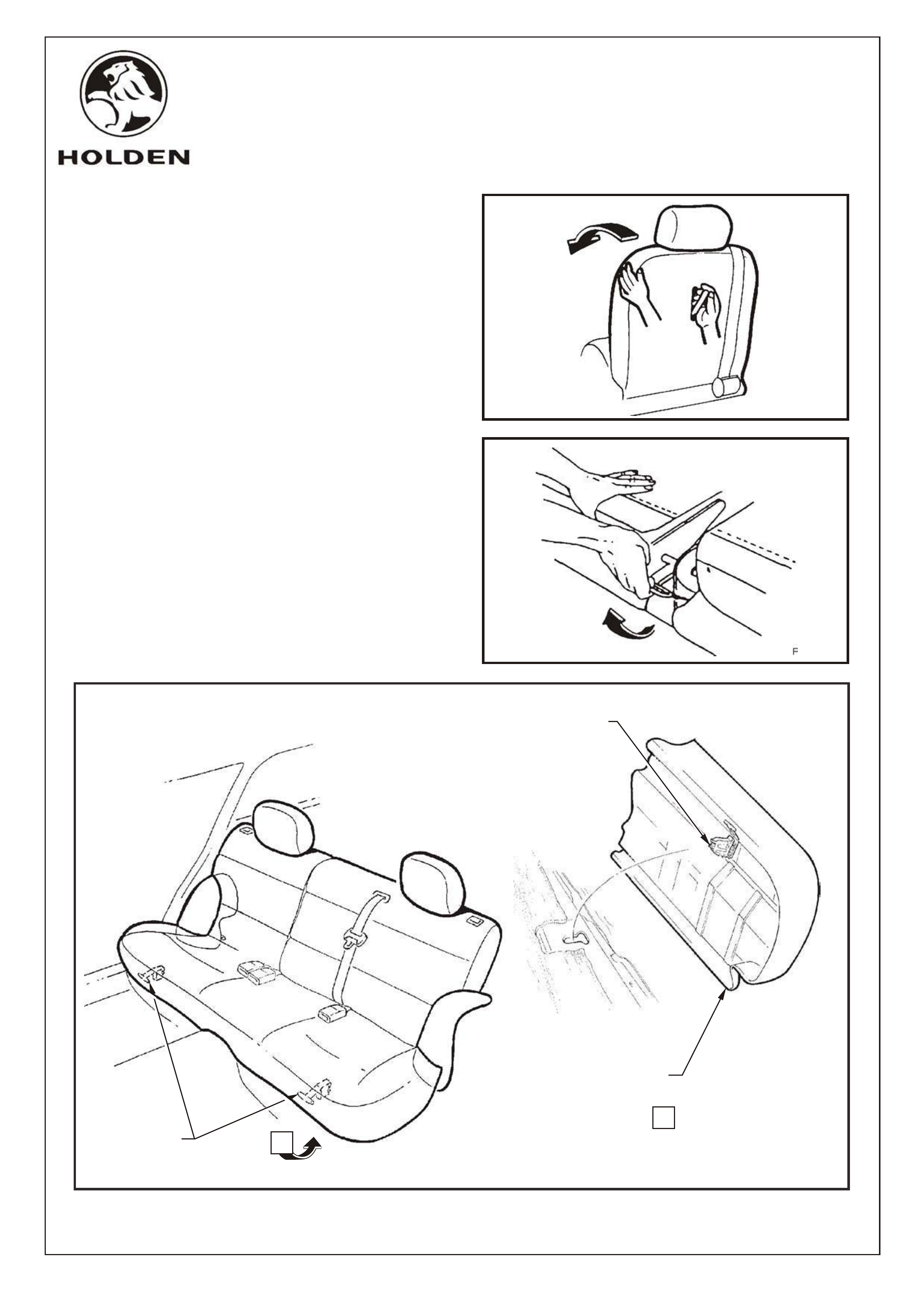
FIGURE 14
FIGURE 13
37. Lock seat down onto rear catches. Make adjustments
to striker positions if necessary.
38. Tighten all M8 bolts to 22Nm and M10 nut to 44Nm.
Seat will require removal from front pivot mounts to
complete tightening.
39. Fold 3rd seat backs forward (if in upright position),
refer figure 13. Unlock and lift seat to stowage
position, refer figure 14.
40. Lift front of rear seat cushion slightly to gain access to
rear seat cushion release handles, refer figure 15.
41. Remove rear seat cushion by pulling release handles
downwards and lifting the front or the cushion, refer
figure 15.
FIGURE 15
RELEASE
HANDLE
VIEW A
A1 PLACE R&L SIDE
REAR SEAT CUSHION
RELEASE HANDLE
& LOCK MECHANISM
REAR SEAT
CUSHION
COPYRIGHT
Page 6 of 8
HOLDEN SERVICE PARTS OPERATIONS
Reproduction in whole or part
prohibited without written approval
Division of HOLDEN Ltd ACN 006 893 232
FD840
25OC02
G727
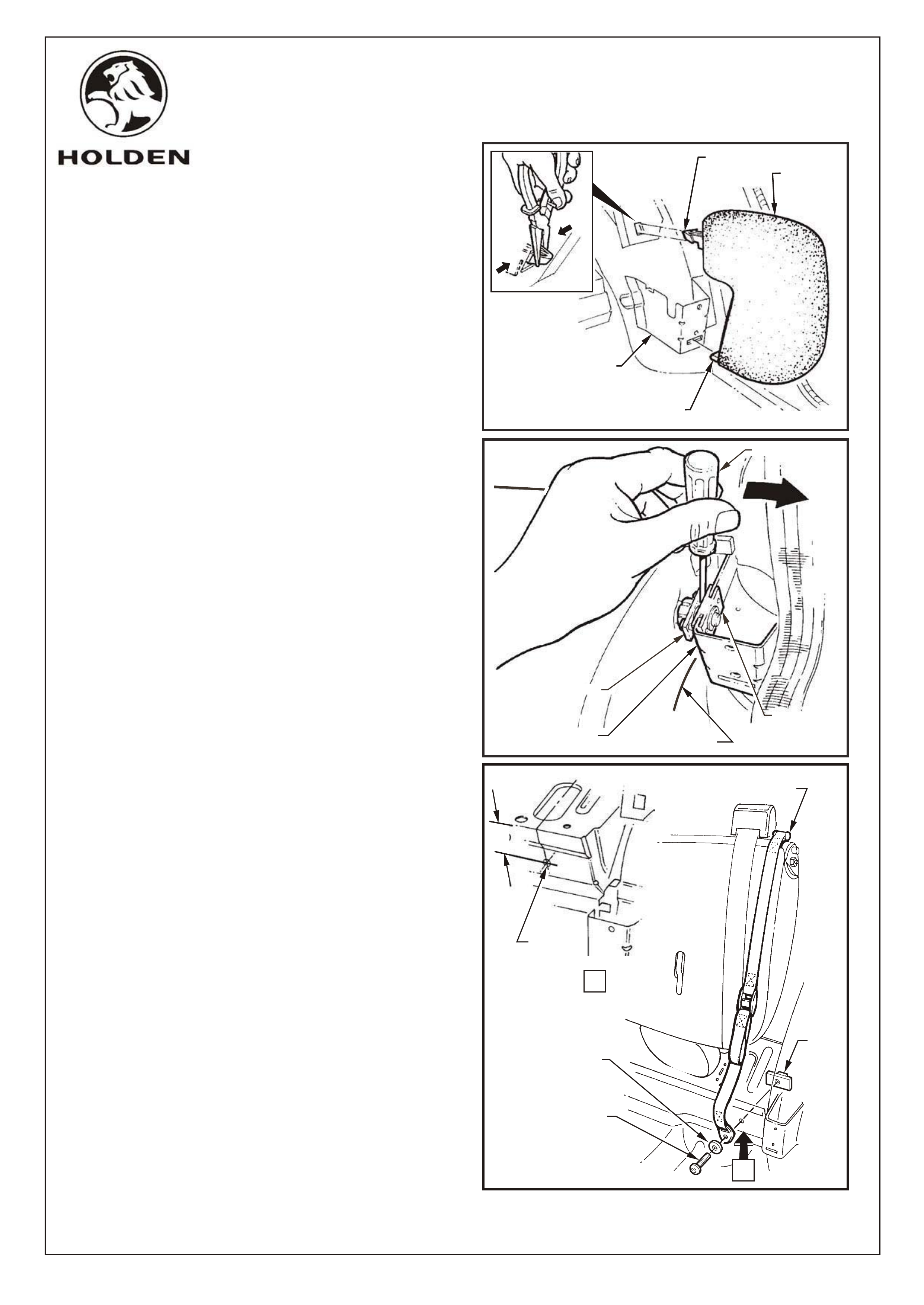
42. With rear seat back lowered, use pliers to squeeze
tangs of the upper bolster retaining clip together and
pull the bolster forward, refer figure 16.
43. Lift bottom of bolster lower retaining tang up, pull
bolster forward and remove, refer figure 16.
44. Insert a srewdriver between seat back retaining plate
and locking plate and pin assembly and gently prise
apart to withdraw pins from retaining plate, refer figure
17.
45. Lift outer end of seat up out of seat back retainer and
pull seat back assembly towards door, withdrawing it
from the seat back centre hinge assembly. Remove
seat back.
46. Hook storage strap to pin near seat belt retractor on
left hand side of 3rd seat base, refer figure 18.
47. Mark and drill 8.5mm dia. hole, 60mm below floorpan
level, for storage strap anchor plate screw, refer figure
18.
48. Install pan head screw and washer to anchor plate. Fit
screw through drilled hole and attach to nut plate.
Use existing access hole in floor to fit nut to screw.
Tighten pan head screw, refer figure 18.
49. Refit LH rear seat back in it's lowered position. Fold
seat into upright position and locking plate and pin
assembly will automatically lock. LH and RH
seatbacks use common central pivot. Ensure both
operate correctly after refit.
50. Reinstall LH bolster and rear seat cushion.
SAFETY PRECAUTION: Remove rear cargo blind (if
fitted), from rear seat back, when third seat is in use.
NOTE: After installation is complete, place Fitting
Instruction booklet in glove box of vehicle.
FIGURE 17
RETAINING
PLATE
LOCKING
PLATE
AND PIN
ASSEMBLY
SCREWDRIVER
SEAT BACK
SEAT BACK
RETAINER
NUT
PLATE
HOOK STORAGE
STRAP TO PIN
FLAT
WASHER
PAN HEAD
SCREW
FIGURE 18
60.0
A
VIEW A
DRILL 8.5
DIA HOLE
COPYRIGHT
Page 7 of 8
HOLDEN SERVICE PARTS OPERATIONS
Reproduction in whole or part
prohibited without written approval
Division of HOLDEN Ltd ACN 006 893 232
RETAINING TANG
RETAINING TANG
BOLSTER
ASSEMBLY
SEAT BACK
RETAINING
BRACKET
FIGURE 16
FD840
25OC02
G727

THIRD SEAT PACKAGE: 1
NOTE: FOR PART NUMBER OF 3RD SEAT PACKAGE
TO SUIT PARTICULAR VEHICLE MODEL AND SEAT FABRIC, CONTACT DEALER
92056895 INSTALLATION HARDWARE PACKAGE 1
CONSISTS OF:
KIT ASSEMBLY-STORAGE STRAP, CONSISTS OF:
STORAGE STRAP 1
PAN HEAD SCREW 5/16" - UNC x 3/4" (SP3817) 1
FLAT WASHER 3/8" ID x 3/4" OD 1
NUT PLATE 5/16" UNC 1
KIT FIXING-PIVOT MOUNTING LH, CONSISTS OF:
PLASTIC COVER-BLACK-FRONT PIVOT MOUNTING 1
RIVET PLASTIC 4.6 DIA x 4.8 LONG 3
BOLT M8 x 30 2
SPRING WASHER 8.0 ID 2
FLAT WASHER 8.0 ID x 22.0 OD 2
BOLT M8 x 45 1
NUT "NYLOC" M8 1
NUT PLATE 1
FRONT PIVOT MOUNTING 1
KIT FIXING-FRONT PIVOT MOUNTING RH, CONSISTS OF:
PLASTIC COVER-BLACK-FRONT PIVOT MOUNTING 1
RIVET PLASTIC 4.6 DIA x 4.8 LONG 3
BOLT M8 x 30 2
SPRING WASHER 8.0 ID 2
FLAT WASHER 8.0 ID x 22.0 OD 2
BOLT M8 x 45 1
NUT "NYLOC" M8 1
NUT PLATE 1
FRONT PIVOT MOUNTING 1
KIT ASSEMBLY-STRIKER & REAR MOUNTING LH, CONSISTS OF:
SCREW M10 x 100 1
NUT "NYLOC" M10 1
BOLT M8 x 30 1
SPRING WASHER 8.0 ID 1
CUP WASHER 46.5 OD x 10.5 10.5 ID x 2.5t (92001572) 1
STRIKER PLATE 1
NUT PLATE 1
KIT ASSEMBLY-STRIKER & REAR MOUNTING RH, CONSISTS OF:
BOLT M8 x30 2
SPRING WASHER 8.0 ID 2
STRIKER PLATE 1
NUT PLATE 1
MOUNTING TEMPLATE IN CARDBOARD TUBE 1
FD796 WARRANTY CARD 1
FD840 FITTING INSTRUCTION BOOKLET 1
VT - VY WAGON THIRD SEAT PACKAGE
(Part No. 92043234)
PARTS LIST
PART NUMBER DESCRIPTION QUANTITY
COPYRIGHT
Page 8 of 8
HOLDEN SERVICE PARTS OPERATIONS
Reproduction in whole or part
prohibited without written approval
Division of HOLDEN Ltd ACN 006 893 232
FD840
25OC02
G727