FITTING INSTRUCTIONS FOR
VT SUPER LIFT SHOCK ABSORBER PACKAGE (SEDAN)
Part No. 92140089
FD858
02AU99
COPYRIGHT
Page 1 of 5
FD858-1
HOLDEN SERVICE PARTS OPERATIONS
Reproduction in whole or part
prohibited without written approval
Division of HOLDEN Ltd ACN 006 893 232
HSPO2-SH.CDR

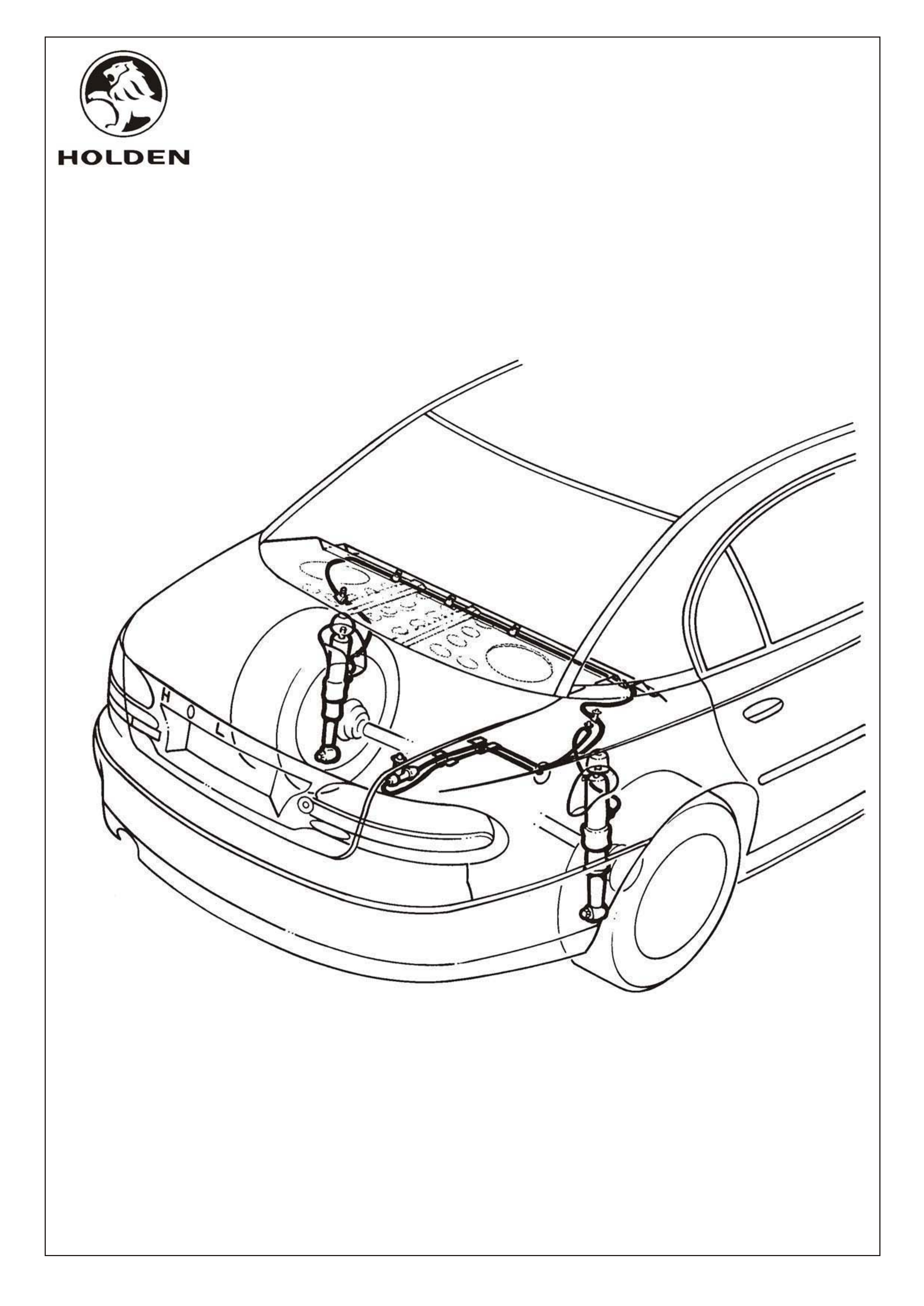
VT SUPER LIFT SHOCK ABSORBER PACKAGE
FITTING INSTRUCTIONS (SEDAN)
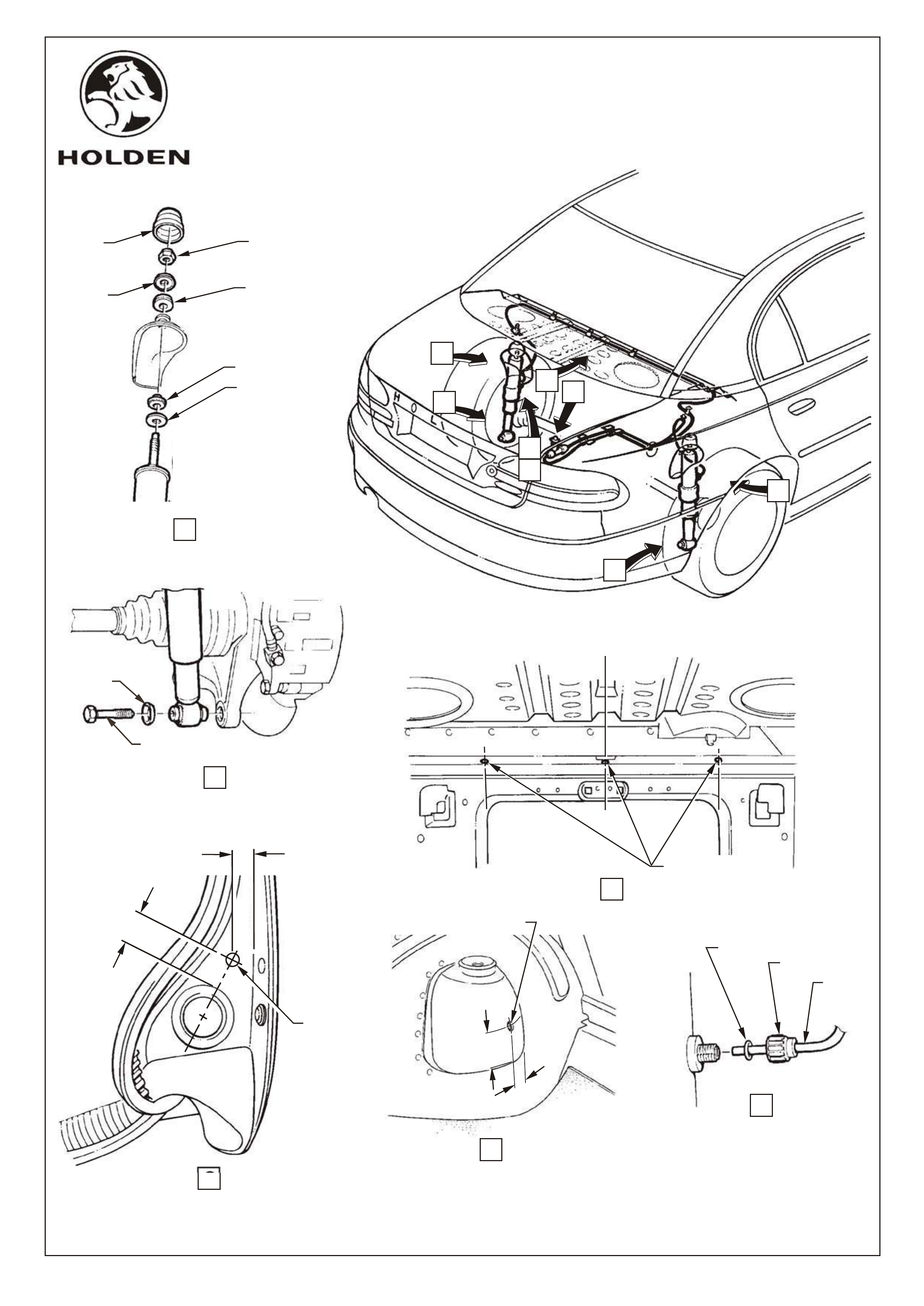
1. Remove existing rear shock absorbers, refer figure 1, views A & B.
2. Centre punch and drill 8.0mm hole for valve mounting in RH body panel, at location shown in figure 1, view C.
3. With shock absorbers removed, mark drilling locations on shock absorber turrets as shown on figure 1, view D. Centre
punch and drill 6.0mm dia. holes, one each side.
4. Centre punch and drill 6.0dia. holes(three places) in underside of rear shelf for air line clips, as shown in figure 1, view E.
5. Debur all drilled holes and coat with anti-corrosion primer.
6. Insert grommets to holes in shock absorber turrets.
7. Fit both Super Lift shock absorbers with air line connections facing front of vehicle
Torque lower shock absorber mounting bolts 105-125Nm.
8. Feed approximately 50mm of air line through grommet in LH shock absorber turret from inside rear compartment. Attach
air line to LH shock absorber using 'O' ring and cap refer figure 1, view F.
NOTE: Tape up open end of air line to prevent entry of foreign matter during routing.
9. Route air line up through hole in LH gusset (under rear parcel shelf)refer figure 2, view G, across and through hole in RH
gusset, refer figure 2 view H.
10. Clip air line to parcel shelf at hole locations drilled previously (3 places), refer figure 1, view E.
11. Route air lines through existing hole, behind side panel to valve location as shown figure 2, view H, cut air line to suit.
12. Attach air line from LH shock absorber to valve, using 'O' ring and cap. Attach remaining air line to valve using 'O' ring
and cap. Refer figure 2, view J.
13. Fit 'T' valve assembly to drilled hole in RH body panel using pressure guide label, washer and nut, refer figure 2, view J.
14. Route RH shock absorber air line parallel to LH shock absorber air line, behind side panel and through hole. Use existing
wiring harness clips to secure air lines along under side of body side panel, refer figure 2, view H.
15. Route air line down and through grommet to RH shock absorber, refer figure 2, view H.
16. Cut air line to length and attach to RH shock absorber using 'O' ring and cap, refer figure 1, view F.
17. Ensure air lines are free of kinks or other interference. Inflate shock absorbers to maximum pressure, 1030kPa (150psi)
and check all connections for leaks.
IMPORTANT: MINIMUM PRESSURE 100kPa (15p.s.i.)
MAXIMUM PRESSURE 1030kPa (150p.s.i.)
Do not exceed 1030 kPa (150p.s.i.) regardless of load
Extremely heavy loads will prevent the attainment of normal height with maximum air pressure.
NOTE: Units should not be inflated so as to exceed vehicle manufacturers designed standard ride height.
FD858
02AU98
COPYRIGHT
Page 2 of 5
FD858-2
HOLDEN SERVICE PARTS OPERATIONS
Reproduction in whole or part
prohibited without written approval
Division of HOLDEN Ltd ACN 006 893 232
HSPO2-SH.CDR
A
H
B
CAP
COVER
UPPER
PLATE
NUT
UPPER BUSH
LOWER BUSH
LOWER PLATE
VIEW A
VIEW B
WASHER
MOUNTING BOLT
VIEW D
VIEW E
VIEW F
VIEW C
DRILL 8.0 DIA
HOLE
25.0
17.0
D
C
F
G
'O' RING
DRILL
6.0 DIA HOLE
AIR LINE CAP
AIR LINE
50,0
40,0
C
L
DRILL 6.0 DIA. HOLES
FOR AIR LINE CLIPS
E
FD858
02AU99 Figure 1
COPYRIGHT
Page 3 of 5
FD858-3
HOLDEN SERVICE PARTS OPERATIONS
Reproduction in whole or part
prohibited without written approval
Division of HOLDEN Ltd ACN 006 893 232
HSPO2-SH.CDR

VIEW K
VIEW J
AIR
LINE
NUT
WASHER
PRESSURE
GUIDE LABEL
CAP
'O' RING
(2 PLACES)
'T' VALVE
AIR LINE CAP
(2 PLACES)
J
EXISTING WIRING
HARNESS CLIPS
(2 PLACES)
L
VIEW
DETAIL 'M'
(3 PLACES)
L
K
VIEW G
LH SIDE
VIEW H
RH SIDE
REFER DETAIL 'M'
REFER DETAIL 'M'
FD858
02AU99 Figure 2
COPYRIGHT
Page 4 of 5
FD858-4
HOLDEN SERVICE PARTS OPERATIONS
Reproduction in whole or part
prohibited without written approval
Division of HOLDEN Ltd ACN 006 893 232
HSPO2-SH.CDR

PART NUMBER DESCRIPTION QUANTITY
FITTING INSTRUCTIONS
VT SUPER LIFT SHOCK ABSORBERS PACKAGE,
SEDAN (92140089)
Parts List
920475470 SUPER LIFT SHOCK ABSORBER ASM. 2
MOUNTING KIT - SHOCK ABSORBER,(TWO KITS PER PACKAGE)
CONSISTS OF:
11092721 NUT 1
92001572 RETAINER WASHER - UPPER 1
92042513 RUBBER CUSHION - UPPER 1
92030409 RUBBER CUSHION - LOWER 1
92021502 RETAINER WASHER - LOWER 1
KIT - AIR LINE, CONSISTS OF:
NUT 1
VALVE CAP - PLASTIC 1
WASHER - PLASTIC 1
LABEL - PRESSURE GUIDE 1
CAP - AIR LINE FITTING 4
AIR LINE - NYLON 1
GROMMET SET 1
' T' VALVE 1
'O' RING 4
INSTRUCTION SHEET('T' VALVE ASSEMBLY) 1
92056424 CLIP - AIR LINE TO BRAKE LINE 6
FD858 FITTING INSTRUCTIONS BOOKLET 1
FD858
02AU99
COPYRIGHT
Page 5 of 5
FD858-5
HOLDEN SERVICE PARTS OPERATIONS
Reproduction in whole or part
prohibited without written approval
Division of HOLDEN Ltd ACN 006 893 232
HSPO2-SH.CDR