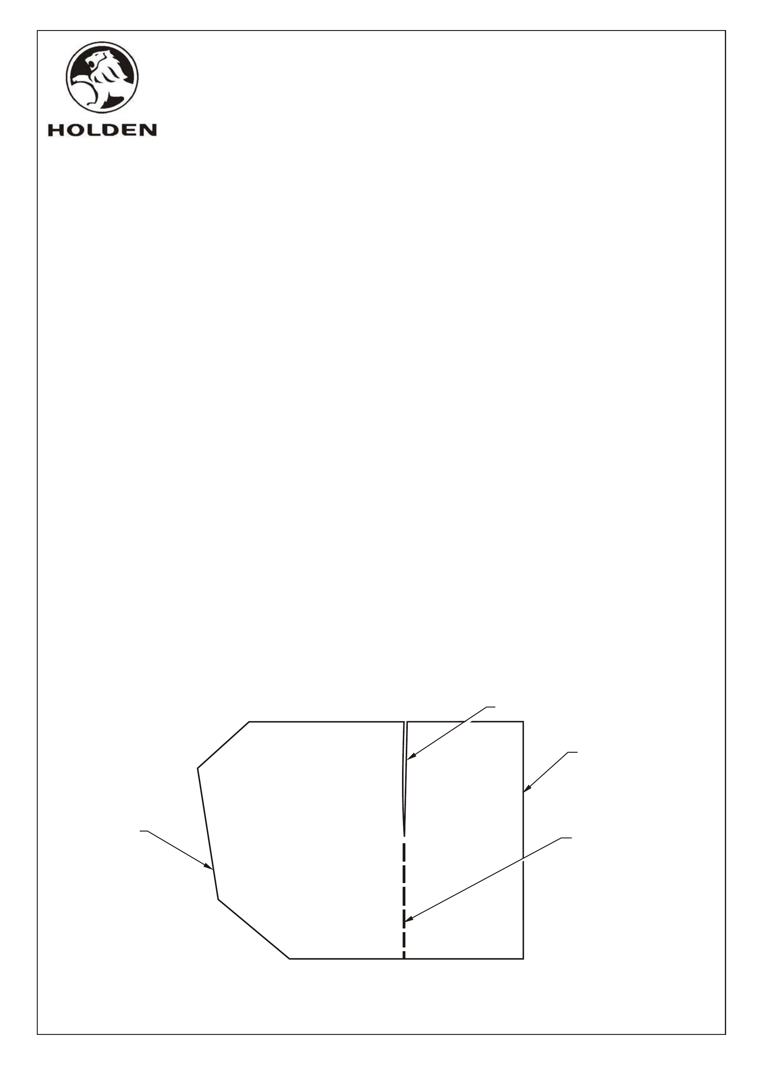
Figure 1
FITTING INSTRUCTIONS
FOR VT COMMODORE HEAT SHIELDS
Part Number 92059847
FITTING INSTRUCTIONS
1. Remove spare wheel from spare wheel well.
2. Sedan - Remove jack handle and jack from stowage compartment. Remove jack stowage
compartment, refer VT Service Manual.
3. Clean floor and spare wheel well on LH side of rear compartment where adhesive foil heat shield shall be
attached.
4. Wagon - Mark a line on the heat shield as a continuation of the existing slit. Cut along this line and
use the rectangular section for wagon heat shield, refer Figure 1. Peel paper backing from
shield. Align one edge of shield to top edge of spare wheel well, starting rear edge of shield
aproximately 20mm from rear panel, as shown in Figure 2, view A. Attach remainder of foil to wall
of spare wheel well.
Sedan - Peel paper backing from heat shield. Attach sheild to floor, first aligning section of sheild
attaching to spare wheel well wall then section across rear compartment floor and lastly
section into jack stowage area wall, refer Figure 2, view B.
NOTE: Attach foil to sheet metal as smoothly as possible.
5. Refit spare wheel to spare wheel compartment.
6. Sedan - Refit jack stowage compartment then stow jack handle and jack.
USE THIS PORTION
OF HEAT SHIELD
FOR WAGON
CUT HERE
EXISTING SLIT
HEAT SHIELD TRIMMING DIRECTIONS
(FOR WAGON ONLY)
DISCARD PORTION OF
HEAT SHIELD WHICH IS
NOT REQUIRED
FD859
30AP98
COPYRIGHT
Page 1 of 4
3365a-01
HOLDEN SERVICE PARTS OPERATIONS
Reproduction in whole or part
prohibited without written approval
Division of HOLDEN Ltd ACN 006 893 232
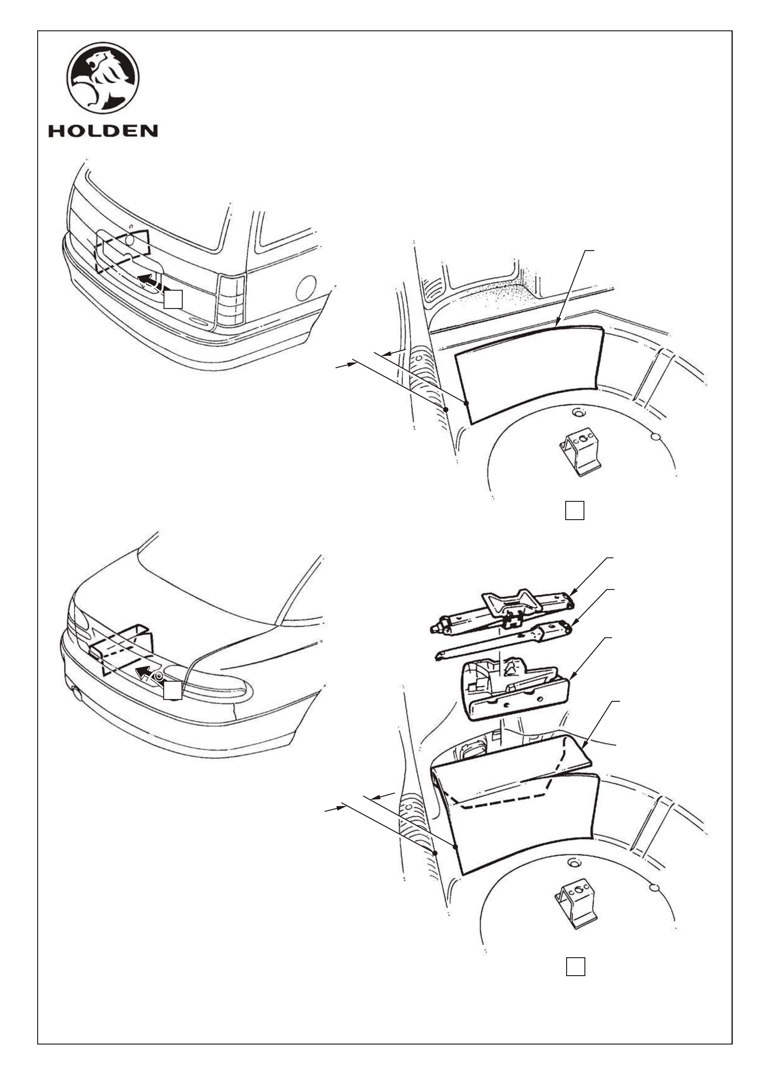
JACK
JACK HANDLE
JACK STOWAGE
COMPARTMENT
HEAT SHIELD
20MM
20MM
HEAT SHIELD
A
B
VIEW A
VIEW B
SEDAN
WAGON
FD859
30AP98 Figure 2
COPYRIGHT
Page 2 of 4
3365a-02
HOLDEN SERVICE PARTS OPERATIONS
Reproduction in whole or part
prohibited without written approval
Division of HOLDEN Ltd ACN 006 893 232
FITTING INSTRUCTIONS
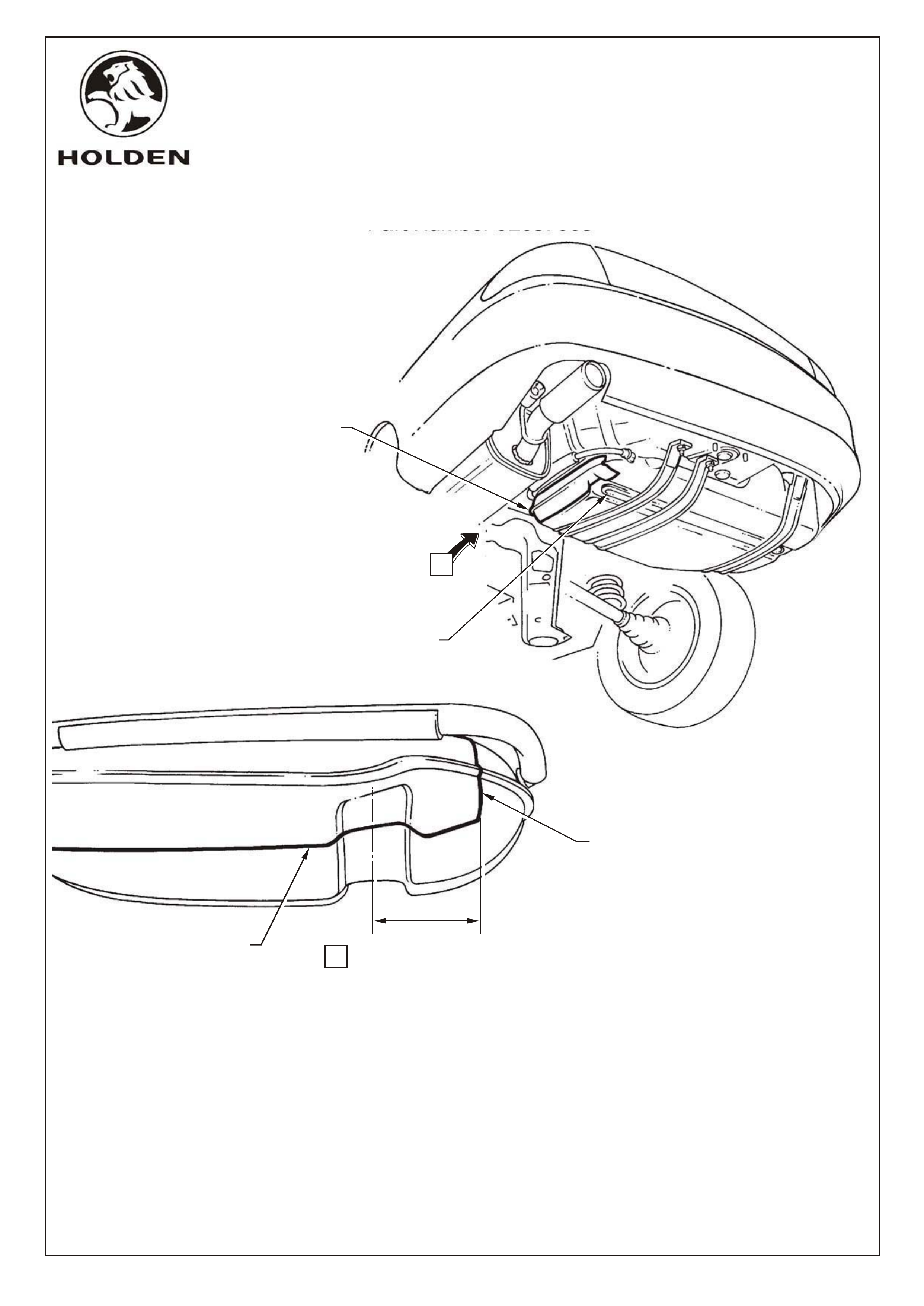
FOR VT COMMODORE FUEL TANK HEAT SHIELD
Part Number 92037805
FITTING INSTRUCTIONS
1. Thoroughly wash side of tank using warm soapy water and a coarse scrubbing brush to
remove dirt. Wipe tank dry.
2. Wipe side of tank with an oil and wax removing solvent (eg. Prepsol) and wipe dry.
3. Position rear edge of patch 90 to 100 mm past centre line of steel lateral support strap,refer view 'A'
NOTE: Prewarm butyl patch before applying by hand ensuring entire area of patch adheres to tank.
90 - 100 mm
SELF ADHESIVE
HEAT SHIELD
VIEW A
A
SELF ADHESIVE
HEAT SHIELD
STEEL LATERAL
SUPPORT STRAP
BEGIN ATTACHING
HEAT SHIELD AT
THIS POINT
C
L
FD859
30AP98
COPYRIGHT
Page 3 of 4
3365a-03
HOLDEN SERVICE PARTS OPERATIONS
Reproduction in whole or part
prohibited without written approval
Division of HOLDEN Ltd ACN 006 893 232
FITTING INSTRUCTIONS FOR
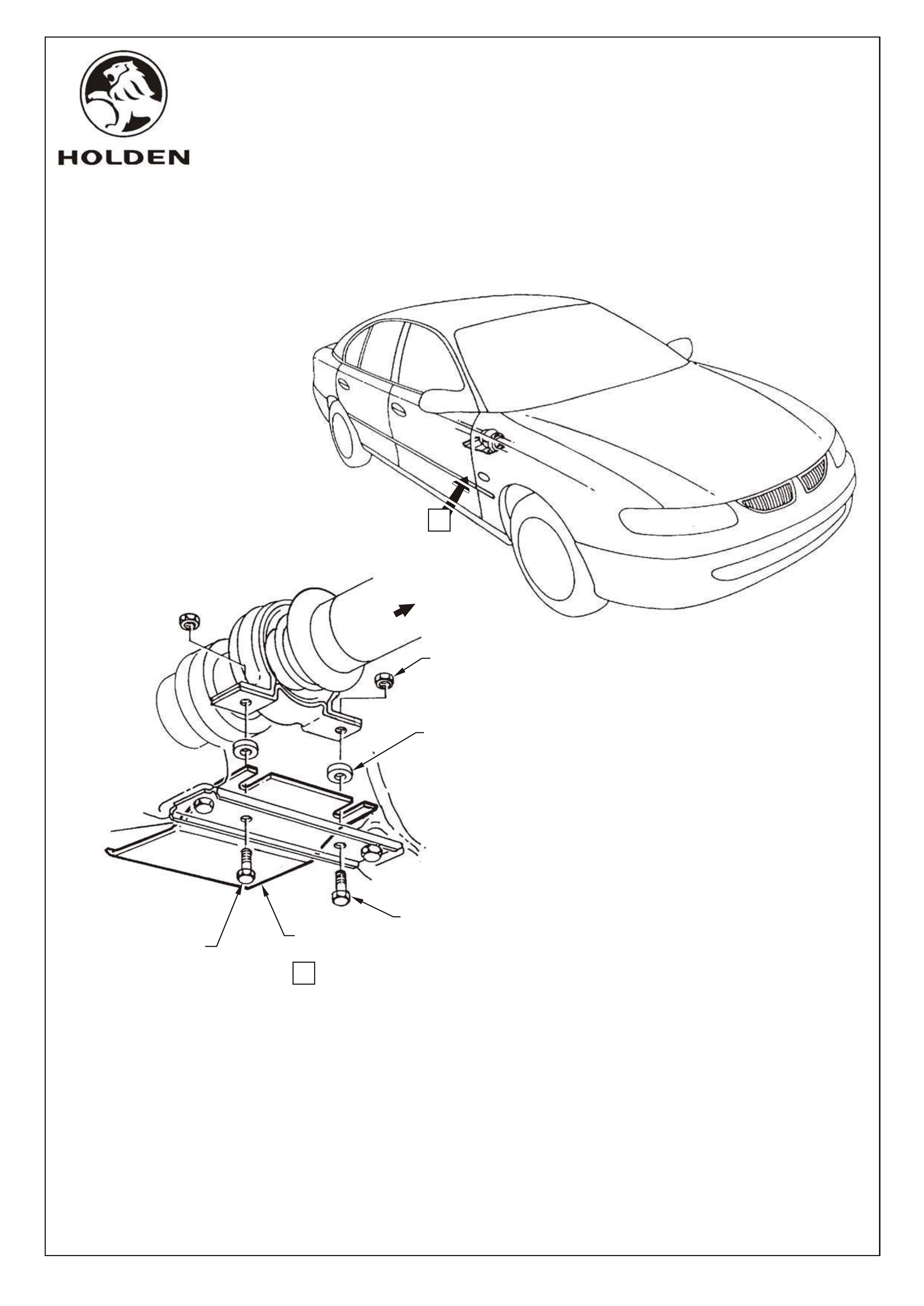
VT COMMODORE CENTRE BEARING HEAT SHIELD
Part Number 92053241
FITTING INSTRUCTIONS
1. Loosen centre bearing carrier to underbody retaining bolts, DO NOT REMOVE BOLTS.
2. Slide centre bearing heat shield on top of centre bearing carrier and tighten to correct torque
specification, refer view A.
CENTRE BEARING TO LOWER CUP GUIDE RETAINING BOLT TORQUE SPECIFICATION 20-25Nm
A
LOOSEN CENTRE BEARING
CARRIER BOLTS.
RETIGHTEN AFTER
INSTALLATION OF
HEAT SHIELD, 20 - 35Nm
NUT - EXISTING
(2 PLACES)
SPACER - EXISTING
(2 PLACES)
HEAT SHIELD -
CENTRE BEARING
BOLT - EXISTING
(2 PLACES)
FRONT OF
VEHICLE
VIEW A
FD859
30AP98
COPYRIGHT
Page 4 of 4
3365a-04
HOLDEN SERVICE PARTS OPERATIONS
Reproduction in whole or part
prohibited without written approval
Division of HOLDEN Ltd ACN 006 893 232