NOTE: This Cruise Control Package must not be
installed to vehicles fitted with traction control.
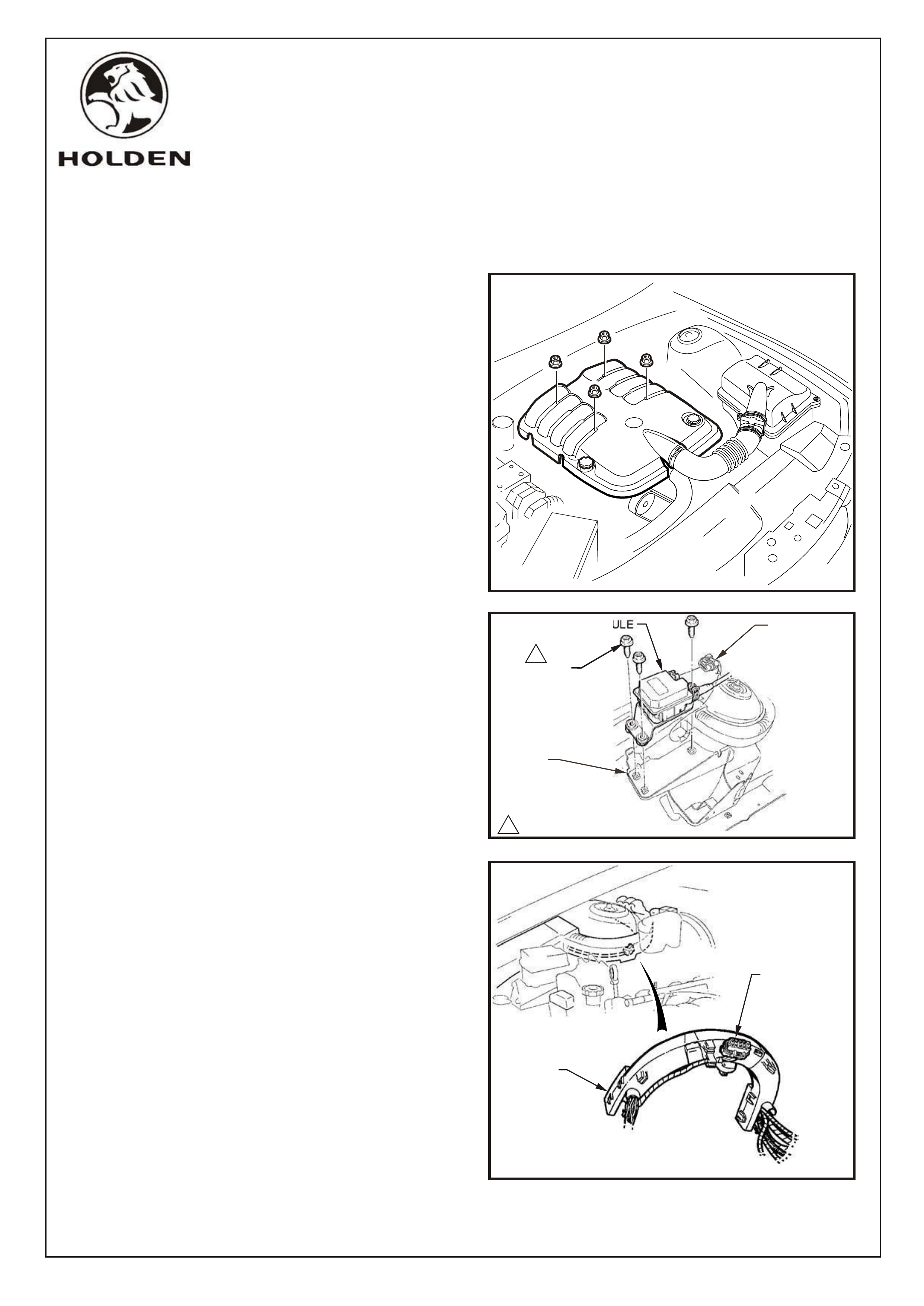
1. Disconnect vehicle battery.
2. Remove four nuts securing the engine dress cover
and remove cover, refer Fig 1.
3. Install stepper motor to mounting bracket using 3
screws supplied and tighten (2 - 5Nm), refer Fig 2.
4. Unclip stepper motor connector from underside of
strut tower former and connect to stepper motor, refer
Fig 3.
FITTING INSTRUCTIONS FOR
VT SERIES II CRUISE CONTROL PACKAGE, 5.7L ALLOY V8
Part No. 92083368
HOLDEN SERVICE PARTS OPERATIONS
Division of HOLDEN Ltd ACN 006 893 232
FIGURE 1
FD905
05JL99 FD905-1a
Reproduction in whole or part
prohibited without written approval
COPYRIGHT
Page 1 of 6
FIGURE 3
STEPPER
MOTOR
CONNECTOR
STRUT
TOWER
FORMER
CONTROL MODULE
1
SCREW
(3 PLACES)
1
2 - 5 Nm
WIRING
HARNESS
CONNECTOR
ABS/CRUISE
CONTROL
MODULE
MOUNTING
BRACKET
FIGURE 2
Page 2 of 6
HOLDEN SERVICE PARTS OPERATIONS
Reproduction in whole or part
prohibited without written approval
Division of HOLDEN Ltd ACN 006 893 232
FD905
17MY99 FD905-2
COPYRIGHT
.
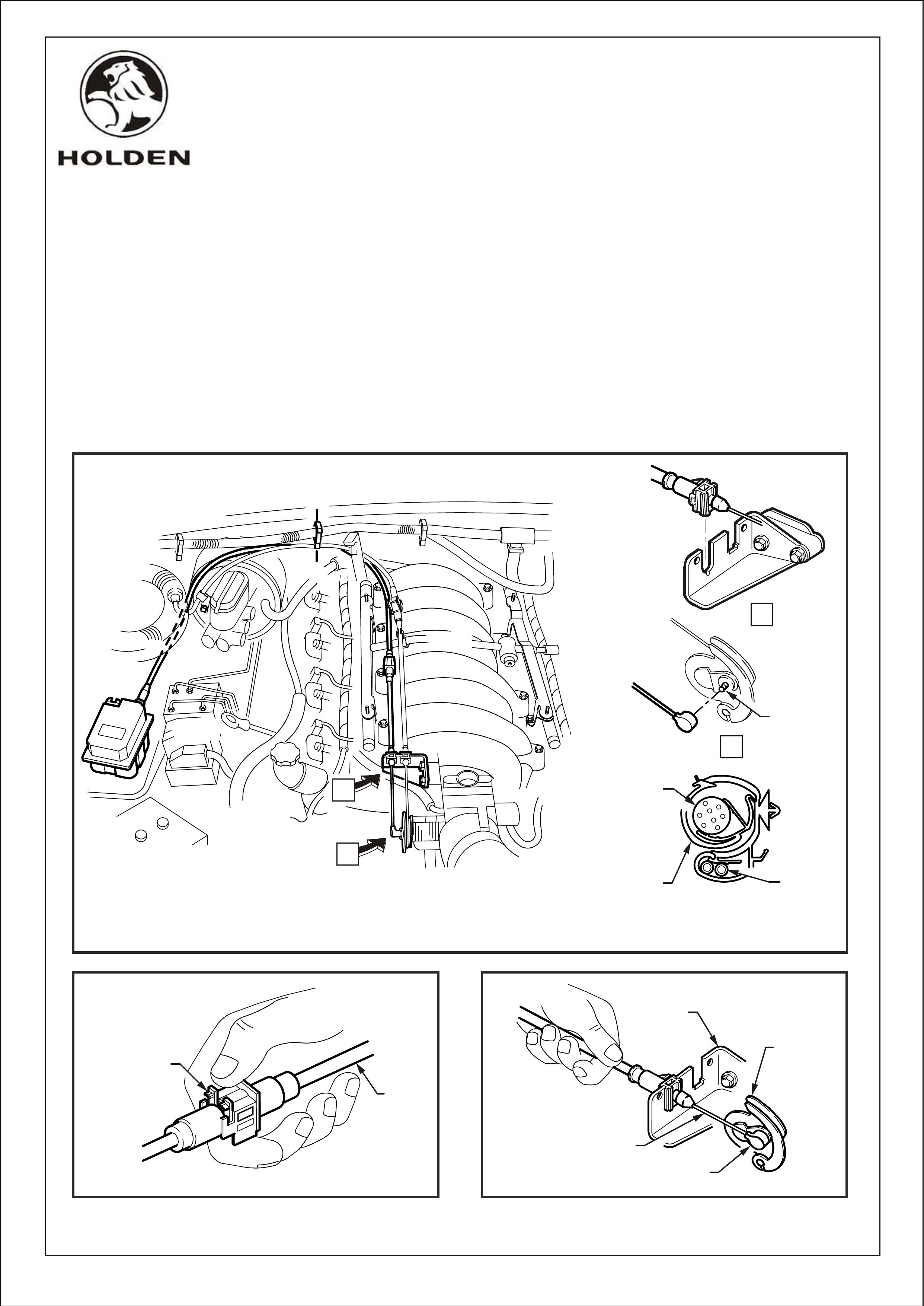
6. Route cable alongside throttle cable and attach to throttle bracket, refer Fig 4, View A.
7. Connect cable end to the stud on throttle valve lever, refer Fig 4, View B.
8. Adjust cable by unlocking the adjustment locking lever, refer Fig 5.
9. Ensure throttle is closed and slide the outer cable to achieve slack in the inner cable, refer Fig 6. Lock
the adjustment locking lever.
engine harness retention clip on edge of firewall, refer Fig 4.
5. Attach cable to rear of stepper motor, route cable below former and drape over brake booster then attach to
FIGURE 6
FIGURE 5
FIGURE 4
A-A
A
A
THROTTLE
STUD
CRUISE
CONTROL
CABLE
HARNESS
RETENTION CLIP
POWER-
TRAIN
WIRING
HARNESS
A
A
B
B
OUTER
CABLE
ADJUSTMENT
LOCKING LEVER
THROTTLE
BRACKET
THROTTLE
VALV E
LEVER
THROTTLE
STUD
INNER
CABLE
COPYRIGHT
Page 3 of 6
HOLDEN SERVICE PARTS OPERATIONS
Reproduction in whole or part
prohibited without written approval
Division of HOLDEN Ltd ACN 006 893 232
FD905
17MY99 FD905-3
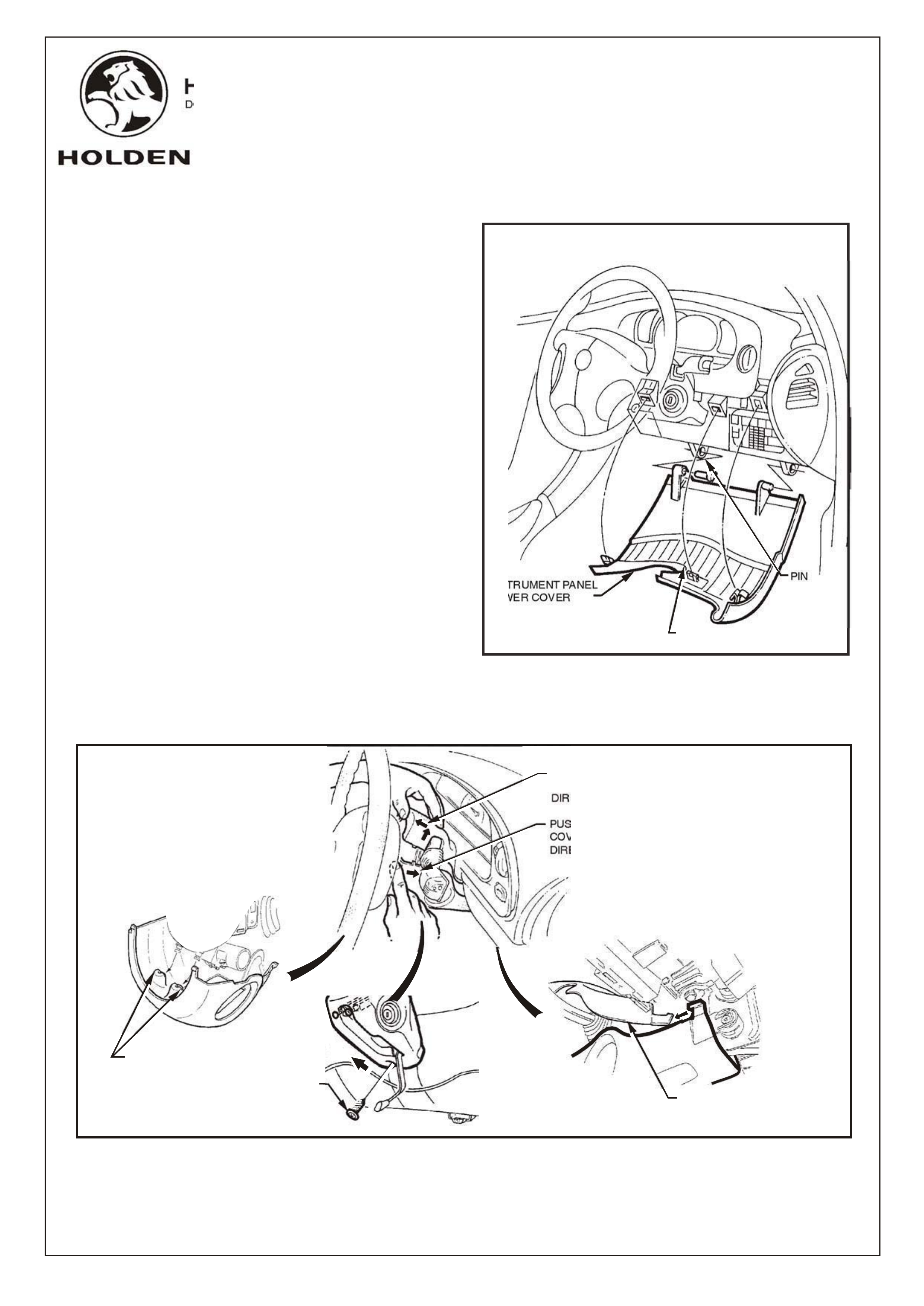
11. Tilt cover down on the left side and disengage the
right hand hinge pin and remove panel, refer Fig 7.
12. Adjust steering wheel to lower most position.
13. Remove single screw from lower steering column
cover, refer Fig 8.
14. Remove upper and lower steering column covers,
refer Fig 8.
screwdriver, refer Fig 7.
out the left hand hinge pin using a flat blade
Repeat procedure for left hand side of cover. Prise
cover panel firmly and pull towards rear of vehicle.
Grasp right hand side of instrument panel lower
10. Adjust steering wheel to upper most position.
FIGURE 7
COVER LOWER
INSTRUMENT PANEL
LOCATING CLIP
3 PLACES
PIN
FIGURE 8
SCREW
LOWER COVER MUST
BE DISENGAGED
FROM COLUMN LUGS
AS SHOWN DISENGAGE UPPER
COVER FROM
LOWER COVER
PUSH LOWER
COVER IN THIS
DIRECTION
PULL UPPER
COVER IN THIS
DIRECTION
COPYRIGHT
Page 3 of 6
HOLDEN SERVICE PARTS OPERATIONS
Reproduction in whole or part
prohibited without written approval
Division of HOLDEN Ltd ACN 006 893 232
FD905
17MY99 FD905-3
11. Tilt cover down on the left side and disengage the
right hand hinge pin and remove panel, refer Fig 7.
12. Adjust steering wheel to lower most position.
13. Remove single screw from lower steering column
cover, refer Fig 8.
14. Remove upper and lower steering column covers,
refer Fig 8.
screwdriver, refer Fig 7.
out the left hand hinge pin using a flat blade
Repeat procedure for left hand side of cover. Prise
cover panel firmly and pull towards rear of vehicle.
Grasp right hand side of instrument panel lower
10. Adjust steering wheel to upper most position.
FIGURE 7
COVER LOWER
INSTRUMENT PANEL
LOCATING CLIP
3 PLACES
PIN
FIGURE 8
SCREW
LOWER COVER MUST
BE DISENGAGED
FROM COLUMN LUGS
AS SHOWN DISENGAGE UPPER
COVER FROM
LOWER COVER
PUSH LOWER
COVER IN THIS
DIRECTION
PULL UPPER
COVER IN THIS
DIRECTION
NOTE: Use Tech 2 to check if globes for two cruise
control lamps are already fitted to instrument cluster. If
cruise control lamps are fitted, go straight to step 19.
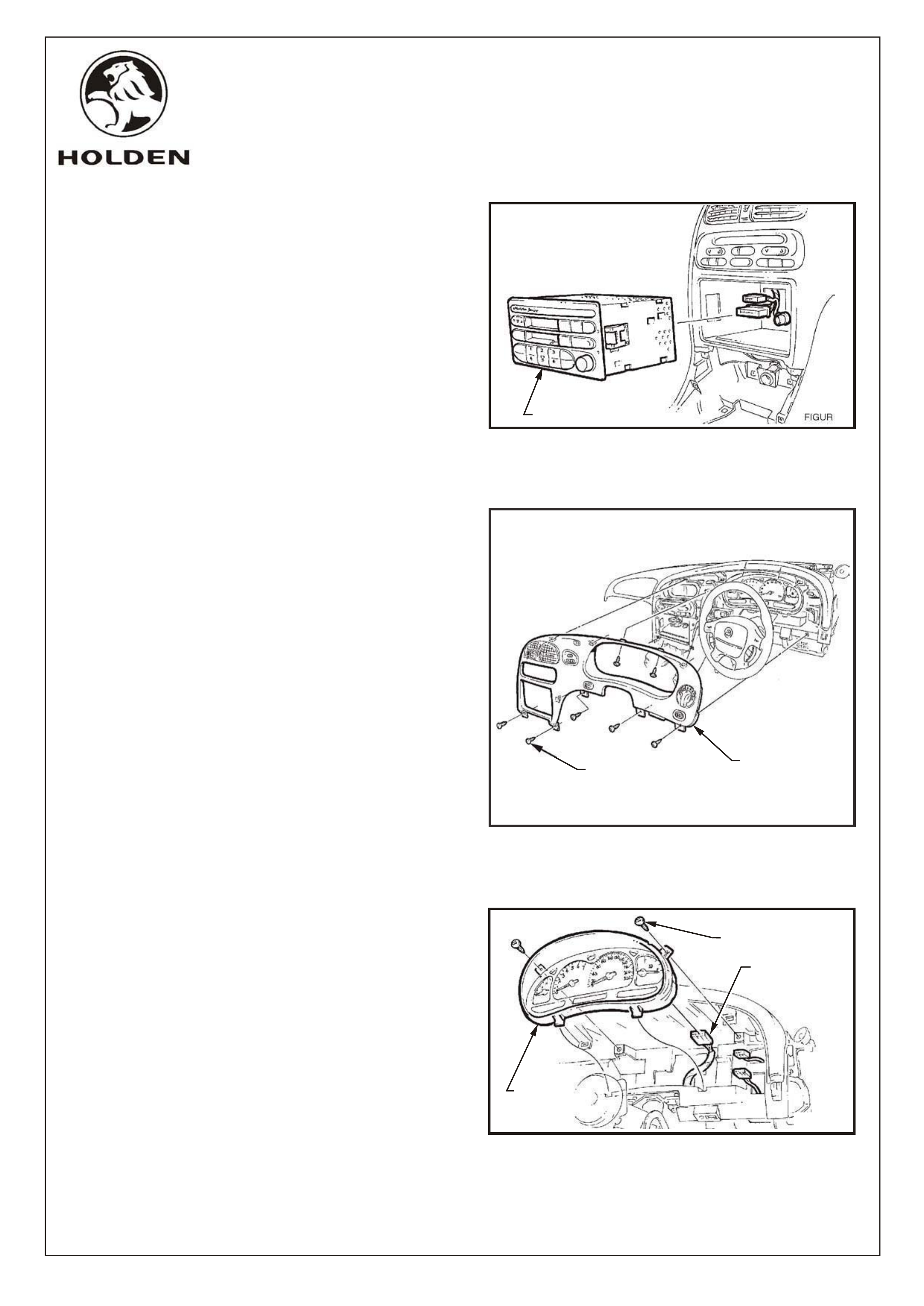
15. Remove radio/cassette/CD from instrument panel.
Disconnect antenna and if fitted, diversity antenna,
refer Fig 9.
16. Remove rubber cap from transmission console and
remove two screws from transmission console.
Prise out transmission console, disconnecting
power windows harness if required.
17. Remove the seven screws retaining the instrument
facia assembly, and pull facia from retaining clips,
refer Fig 10.
NOTE: Disconnect the headlamp switch connector, fog
lamp switch connector (if fitted), trip computer switch
connector (if fitted), hazard switch connector from main
wiring harness, before removing instrument facia
assembly.
18. Remove 2 screws securing the instrument cluster,
and disconnect instrument cluster
connector,remove instrument cluster, refer Fig 11.
FIGURE 9
RADIO/CASSETTE/CD
SCREWS
(2 PLACES)
INSTRUMENT
CONNECTOR
COMBINED
INSTRUMENTS
ASSEMBLY FIGURE 11
FIGURE 10
SCREW
(7 PLACES)
INSTRUMENT
FACIA ASSEMBLY
COPYRIGHT
Page 4 of 6
HOLDEN SERVICE PARTS OPERATIONS
Reproduction in whole or part
prohibited without written approval
Division of HOLDEN Ltd ACN 006 893 232
FD905
05JL99 FD905-4a

19. Fit clip from cruise control package to mounting
hole of the brake pedal support, refer Fig 12.
20. Untape connector from wiring harness and connect
to cruise control release switch.
21. Holding the brake pedal in it's depressed position,
install switch into tubular clip. Push switch forward
until the switch body locates in the clip.
NOTE: Audible 'clicks' will be heard as the threaded
portion of switch assembly is pushed into the tubular
clip toward the brake pedal. Pull brake pedal fully
against stop until audible 'click' sounds can no longer
be heard. (Switch assembly is pushed back out from
the clip to provide correct switch position adjustment).
Depress the brake pedal again and repeat above
procedure to ensure that the switch adjustment is
correct (no 'click' sounds).
22. Install 2 globes for cruise control lamps to rear of
instrument cluster, refer Fig 13.
23. Reconnect connector to instrument cluster and
reinstall instrument cluster with 2 screws.
24. Disconnect RH indicator switch connector, remove
indicator stalk and replace with cruise control/
indicator stalk from cruise control package, refer
Fig 14.
25. For Manual transmission, install clutch switch and
harness as per instruction included in package.
26. Refit steering wheel covers (1 screw).
27. Refit instrument facia if required (9 screws).
28. Refit transmission console (2 screws), refit rubber
cap from transmission console and refit
radio/cassette/CD player if required.
28. Refit instrument panel lower cover .
29. Refit engine cover and engine compartment Relay
box cover.
30. Use Tech 2 to check cruise control programming.
NOTE: After installation, check operation of cruise
control, (including lamps in instrument panel) in
accordance with VT Series Service Manual, Vol. 6,
Section 12C, Instruments, wiper/washers & Horn. Any
problems may be corrected using this section of the
Service Manual. COPYRIGHT
Page 5 of 6
HOLDEN SERVICE PARTS OPERATIONS
Reproduction in whole or part
prohibited without written approval
Division of HOLDEN Ltd ACN 006 893 232
FD905
05JL99 FD905-5a
FIGURE 12
CLIP
ATTACH
CONNECTOR
TO CRUISE
CONTROL
RELEASE
SWITCH
FIGURE 13
INSTAL GLOBES FOR
CRUISE CONTROL LAMPS
(2 PLACES)
INSTRUMENT
CLUSTER
HEADLAMP AND
TURN SIGNAL
CONTROL SWITCH
ASSEMBLY
SWITCH
RETAINING
TANGS STEERING
COLUMN
SWITCH
HOUSING
FIGURE 14
BRAKE
PEDAL
CRUISE CONTROL
RELEASE SWITCH

PART NUMBER DESCRIPTION QUANTITY
VT SERIES II CRUISE CONTROL PACKAGE (92083368),
FOR 5.7L ALLOY V8
Parts List
25180009 STEPPER MOTOR & CABLE ASSEMBLY 1
92138364 BOLT - STEPPER MOTOR TO WHEELHOUSE 3
92054763 SWITCH - TURN SIGNAL/CRUISE 1
9794682 SWITCH - BRAKE 1
1361699 CLIP - CRUISE CONTROL BRAKE SWITCH MOUNT 1
92140551 GLOBE ASSEMBLY - WARNING 2
FD905 FITTING INSTRUCTIONS BOOKLET 1
FD796 WARRANTY CARD 1
NOT INCLUDED IN CRUISE CONTROL PACKAGE, BUT MANDATORY TO FIT (MANUAL ONLY):
92077936 SWITCH - CLUTCH 1
92075048 PATCH HARNESS - CLUTCH SWITCH 1
FD905
17MY99
COPYRIGHT
Page 6 of 6
HOLDEN SERVICE PARTS OPERATIONS
Reproduction in whole or part
prohibited without written approval
Division of HOLDEN Ltd ACN 006 893 232
FD905-6