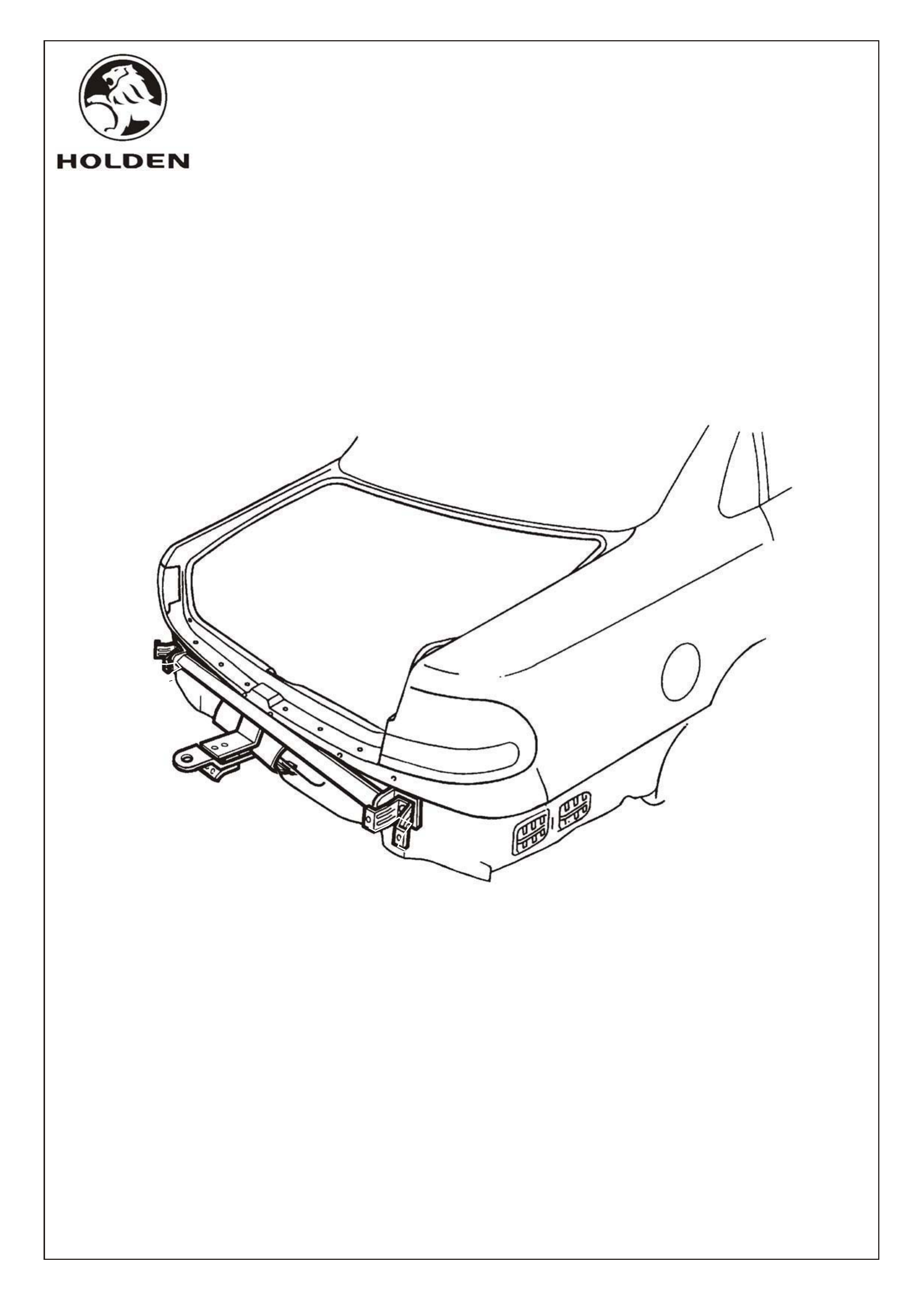
FITTING INSTRUCTIONS FOR
WH STATESMAN & CAPRICE (V6 & 5.7 V8)
1200KG TOW BAR PACKAGE.
HOLDEN SERVICE PARTS OPERATIONS
FD906
28DE99
Division of HOLDEN Ltd ACN 006 893 232
Page 1 of 8
FD906b-1
Reproduction in whole or part
prohibited without written approval
COPYRIGHT
Part Number 92142845
NOT INCLUDED IN TOW BAR PACKAGE, BUT AVAILABLE SEPARATELY:
92140088 TRAILER WIRING HARNESS - FLAT 7 PIN
92140147 TRAILER WIRING HARNESS - ROUND 7 PIN (LARGE PIN)
92140148 TRAILER WIRING HARNESS - ROUND 7 PIN (SMALL PIN WITH BACKING PLATE)
92140126 PACKAGE - LOAD DISTRIBUTION HITCH (FIXED)
92140068 TOW BALL ASSEMBLY (CHROME)
92140106 TOW BALL COVER
SMALL PARTS KIT

HOLDEN SERVICE PARTS OPERATIONS
Reproduction in whole or part
prohibited without written approval
COPYRIGHT
FD906
28DE99
Division of HOLDEN Ltd ACN 006 893 232
Page 2 of 8
FD906b-2
1200KG TOW BAR FITTING INSTRUCTIONS
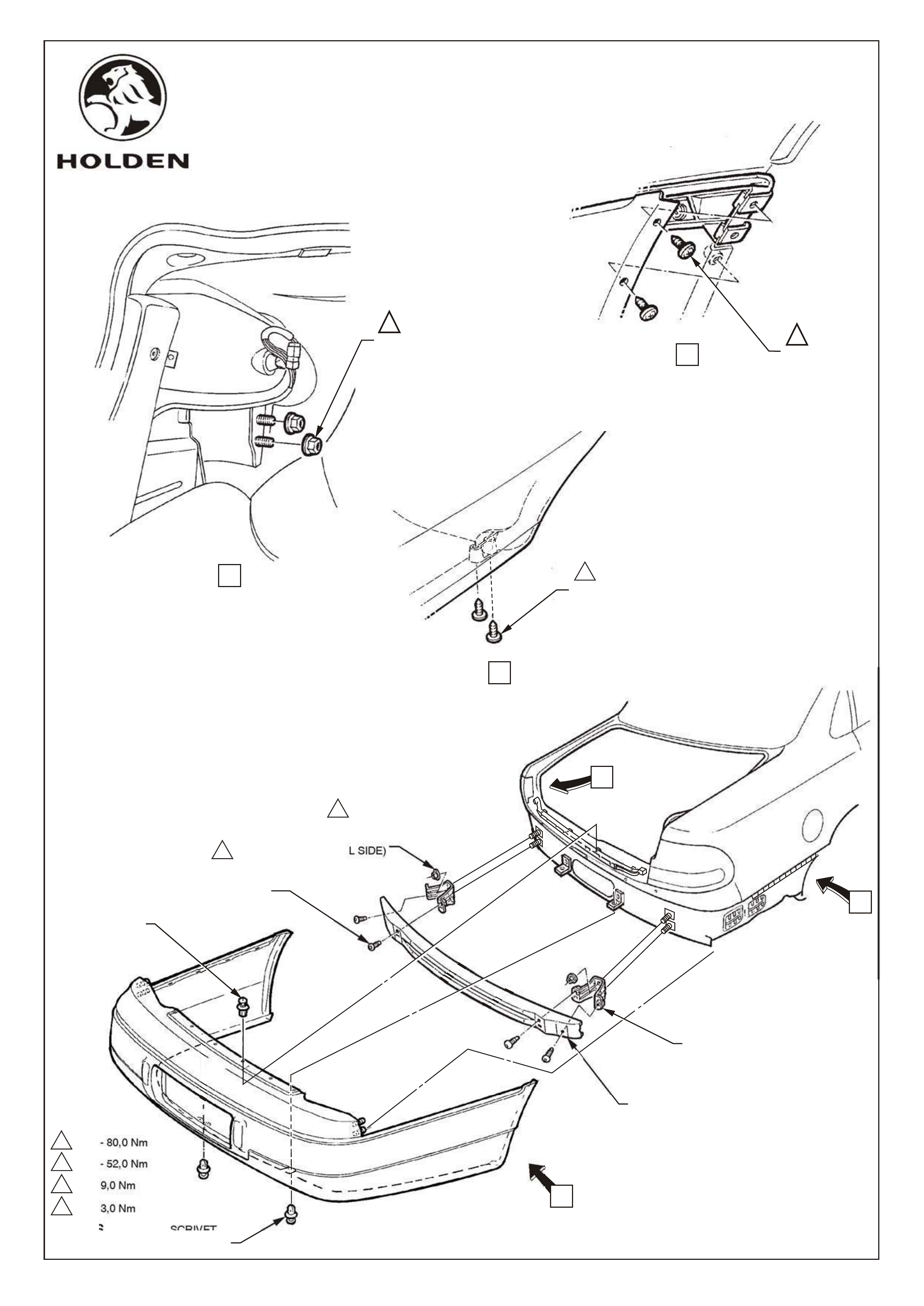
REAR BUMPER BAR SUPPORT BEAM & BRACKETS REMOVAL
Fold side carpets back from rear corners of boot compartment to access nuts securing bumper to body,
refer figure 1, view A.
Remove nuts (2 places each side). Refer figure 1, view A
Remove 4 scrivets at upper edge of facia, refer figure 1.
Remove 2 scrivets, lower facia edge, refer figure 1.
Remove 8 screws, facia to rear edge of wheelhouse, refer figure 1, views B and C.
With facia supported, pull facia sides outward disconnecting facia from side supports and slide rearwards
removing facia, refer figure 1.
Remove 4 bolts securing bumper support beam to brackets,refer figure 1.
Remove 4 nuts securing bumper support beam brackets to vehicle (4 places) and remove brackets,
refer figure 1.
1.
2.
3.
4.
5.
6.
7.
8.
HOLDEN SERVICE PARTS OPERATIONS
FD906
28DE99
Division of HOLDEN Ltd ACN 006 893 232
Page 3 of 8
FD906b-3
1,0 - 3,0 Nm
6,0 - 9,0 Nm
35,0 - 52,0 Nm
50,0 - 80,0 Nm
Figure 1
VIEW B
11
SCREW
(2 PLACES
R & L SIDE)
4
3
2
1
VIEW A
22
NUT
(2 PLACES
R & L SIDE)
NUT
(2 PLACES
R & L SIDE)
REAR BEAM
MOUNTING BRACKET
REAR BUMPER
SUPPORT BEAM ASM.
SCRIVET
(2 PLACES)
BOLT
(2 PLACES
R & L SIDE)
3
4
C
VIEW C
SCREW
(2 PLACES)
R & L SIDE
1
A
B
SCRIVET
(4 PLACES)

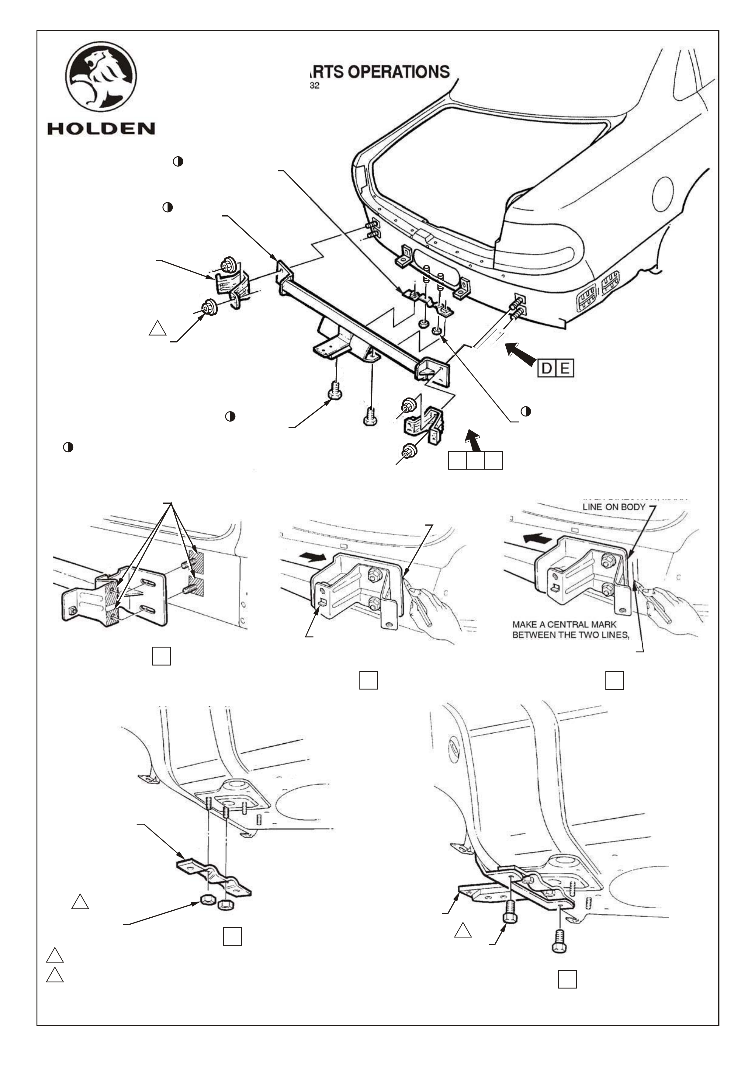
TOW BAR INSTALLATION
Smear a thin film of grease to bare metal exposed by removal of brackets, to vehicle body and rear face of
bracket to prevent corrosion, refer figure 2, view A.
Install spare wheel well support assembly to underside of spare wheel well using two existing rearmost
weldstuds, refer figure 2, view D.
Loosely fit two M10 nuts to weld studs.
Install tow bar to 4 beam support studs, refit beam support brackets over tow bar mounting plates, fit nuts
and hand tighten (4 places).
NOTE : Brackets must be installed with tab on flange inboard of vehicle refer figure 2, view B.
Loosely fit two M10 bolts to attach tow bar main assembly to spare wheel well support assembly.
IMPORTANT: Due to elongated holes in tow bar mounting plates, tow bar will have 10-15mm sideways
travel on rear of car. Tow bar must be accurately centralised on vehicle to ensure bumper
facia cutout aligns with tow bar tongue upon reassembly.
To centralise bar, first slide bar to extremity of travel to RH side of vehicle and mark position of edge of RH
mounting plate on body, refer figure 2, view B.
Slide bar across to extremity of travel to LH side of vehicle and mark RH mounting plate edge position
on body, refer figure 2, view C.
Make a central mark between these two lines (this will centre towbar) & reposition towbar to centre line.
Tighten nuts securing beam support brackets and tow bar mounts to body, 50 - 80Nm (4 places),refer figure 2.
Tighten nuts securing spare wheel well support assembly to underbody weld studs, 30 - 40Nm, (2 places)
Tighten bolts securing main tow bar assembly to spare wheel well support assembly, 30 - 40Nm,
(2 places)
Refit bumper support beam, and tighten bolts 35 - 52Nm.
9.
10.
11.
12.
13.
14.
15.
16.
17.
18.
19.
20.
FD906
28DE99
COPYRIGHT
Page 4 of 8
FD906b-4
HOLDEN SERVICE PARTS OPERATIONS
Reproduction in whole or part
prohibited without written approval
Division of HOLDEN Ltd ACN 006 893 232
HOLDEN SERVICE PARTS OPERATIONS
Reproduction in whole or part
prohibited without written approval
FD906
28DE99
Division of HOLDEN Ltd ACN 006 893 232
Page 5 of 8
REAR BUMPER
BEAM SUPPORT
BRACKET
NUT
(2 PLACES
R &L SIDE)
2
1
2
PART OF TOW BAR PACKAGE
BOLT
(2 PLACES) NUT
(2 PLACES)
TOW BAR
ASSEMBLY
C
A B
D E
30,0 - 40,0 Nm
50,0 - 80,0 Nm
Figure 2
E
D
SLIDE TOW BAR TO
EXTREMITY OF TRAVEL
IN RH DIRECTION, MARK
LINE ON BODY
RH SHOWN
BRACKET MUST
BE INSTALLED
WITH TAB INBOARD
VIEW B
SLIDE TOW BAR TO
EXTREMITY OF TRAVEL
IN LH DIRECTION, MARK
LINE ON BODY
MAKE A CENTRAL MARK
BETWEEN THE TWO LINES,
ALIGN TOW BAR EDGE TO
THIS MARK TO CENTRALISE
TOW BAR
VIEW C
VIEW D
COAT BARE METAL
SURFACES WITH A
THIN FILM OF GREASE
RH SHOWN
VIEW A
NUT
(2 PLACES)
1
SPARE WHEEL WELL
SUPPORT ASM
COPYRIGHT VIEW E
1
BOLT
(2 PLACES)
TOW BAR
ASSEMBLY
SPARE WHEEL WELL
SUPPORT ASSEMBLY
FD906b-5

HOLDEN SERVICE PARTS OPERATIONS
Reproduction in whole or part
prohibited without written approval
COPYRIGHT
FD906
28DE99
Division of HOLDEN Ltd ACN 006 893 232
Page 6 of 8
FD906b-6
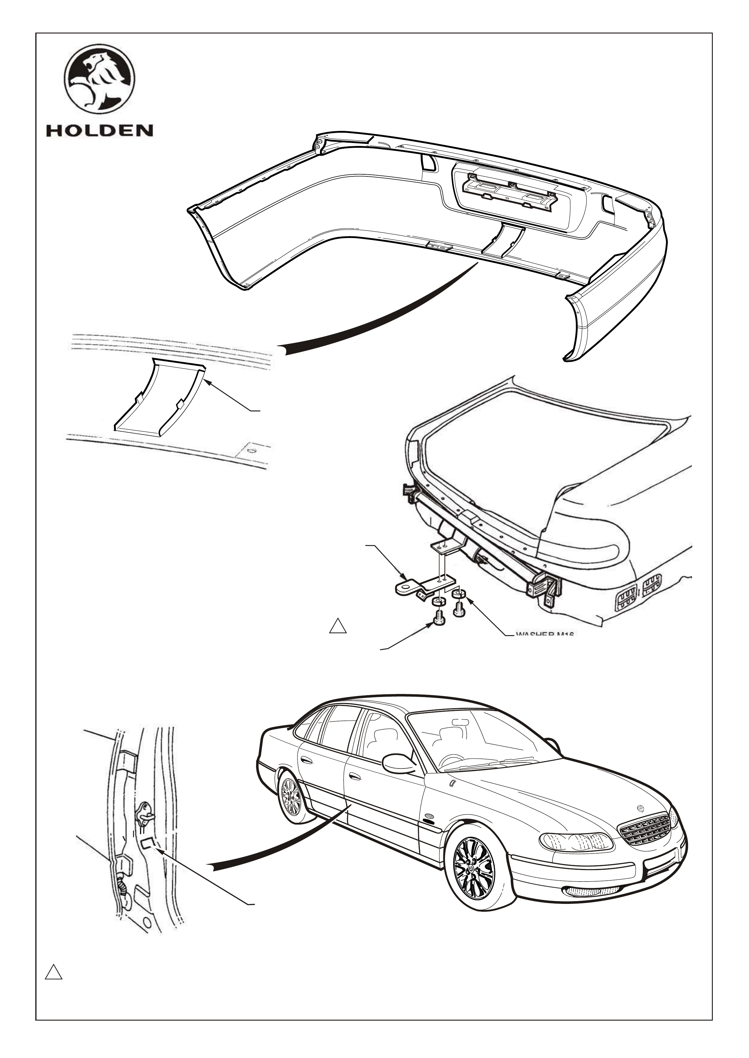
Before facia refit, knock out section in centre of bumper facia to allow protrusion of tow bar
tongue mount, refer figure 3
Reinstall facia in reverse to removal procedure.
NOTE: Align studs on facia correctly through holes in body, below tail light
Install tow bar tongue to tow bar assembly, using two M16 bolts and spring washers, refer figure 3.
Tighten bolts 80 - 90Nm.
Install trailer wiring harness as per fitting instructions included in trailer wiring harness package.
Clean surface of driver's side B pillar and apply ADR label, refer figure 3.
21.
22.
23.
24.
25
NOTE: Once tow bar installation is complete, place Fitting Instruction booklet in glove box of vehicle.
HOLDEN SERVICE PARTS OPERATIONS
FD906
28DE99
Division of HOLDEN Ltd ACN 006 893 232
Page 7 of 8
FD906b-7
80 - 90Nm
Figure 3
1
WASHER M16
(2 PLACES)
BOLT M16
(2 PLACES)
1
TOW BAR TONGUE
Reproduction in whole or part
prohibited without written approval
COPYRIGHT
WIPE SURFACE CLEAN PRIOR
TO APPLICATION OF ADR LABEL
BUMPER FACIA
KNOCKOUT

Reproduction in whole or part
prohibited without written approval
COPYRIGHT
FD906
28DE99
Page 8 of 8
FD906b-8
1200 KG TOW BAR KIT
FOR WH STATESMAN & CAPRICE (V6 & 5.7 V8)
Part Number 92142845
PARTS LIST
TOW BAR ASSEMBLY CONSISTS OF:
TOW BAR MAIN ASSEMBLY 1
SUPPORT ASM. - SPARE WHEEL WELL 1
NUT - M10 2
WASHER - M10 4
BOLT - M10 2
PACKAGE - TOW BAR TONGUE, CONSISTS OF:
TOW BAR TONGUE 1
BOLT - M16 2
SPRING WASHER - M16 2
TOW BAR FITTING INSTRUCTION BOOKLET 1
WARRANTY CARD 1
ADR LABEL 1
'D' RING SAFTEY SHACKLE 1
PART NO. DESCRIPTION QUANTITY
NOT INCLUDED IN TOW BAR PACKAGE, BUT AVAILABLE SEPARATELY:
92140088 TRAILER WIRING HARNESS - FLAT 7 PIN
92140147 TRAILER WIRING HARNESS - ROUND 7 PIN (LARGE PIN)
92140148 TRAILER WIRING HARNESS - ROUND 7 PIN (SMALL PIN WITH BACKING PLATE)
92140126 PACKAGE - LOAD DISTRIBUTION HITCH (FIXED)
92140068 TOW BALL ASSEMBLY (CHROME)
92140106 TOW BALL COVER
SMALL PARTS KIT
HOLDEN SERVICE PARTS OPERATIONS
Division of HOLDEN Ltd ACN 006 893 232
92056261
92056260
92054276
11071063 OR EQUIVALENT
92086071
92086070
FD906
FD796
92077203