
HOLDEN SERVICE PARTS OPERATIONS
Reproduction in whole or part
prohibited without written approval
COPYRIGHT
FD914
28FE00
Division of HOLDEN Ltd ACN 006 893 232
Page 1 of 9
fd914c-1
FITTING INSTRUCTIONS
VT SERIES 2 ANTI-THEFT ALARM PACKAGE
Part Number 92142888
DEALER
FIT
ONLY

HOLDEN SERVICE PARTS OPERATIONS
Reproduction in whole or part
prohibited without written approval
COPYRIGHT
FD914
28FE00
Division of HOLDEN Ltd ACN 006 893 232
Page 2 of 9
fd914c_2
1. Disable air bag as per GMH service requirement.
2. Disconnect main battery terminal.
3. Sedan - Pull down RH inner trim from behind the boot lid hinge to expose the wiring behind the rear
seat back.
Wagon - Remove trim from the RH rear seat back to the RH "D" pillar to expose the wiring.
4. Remove rear seat squab and RH rear seat back.
5. Remove RH sill moulding and RH front kick panel.
6. Remove fuse access panel and pedal box cover.
7. Remove diagnostics connector and fuse box support bar.
8. Remove the air ducts (2 pieces) from behind the fuse box and remove the RH dash end cover.
9. Remove fuse panel from mounting bracket.
10. Remove glove box and lower trim panel.
11. Remove the RH and LH centre console trim panels.
12. Remove the screw from the LH kick panel to allow the carpet and underlay to be folded back.
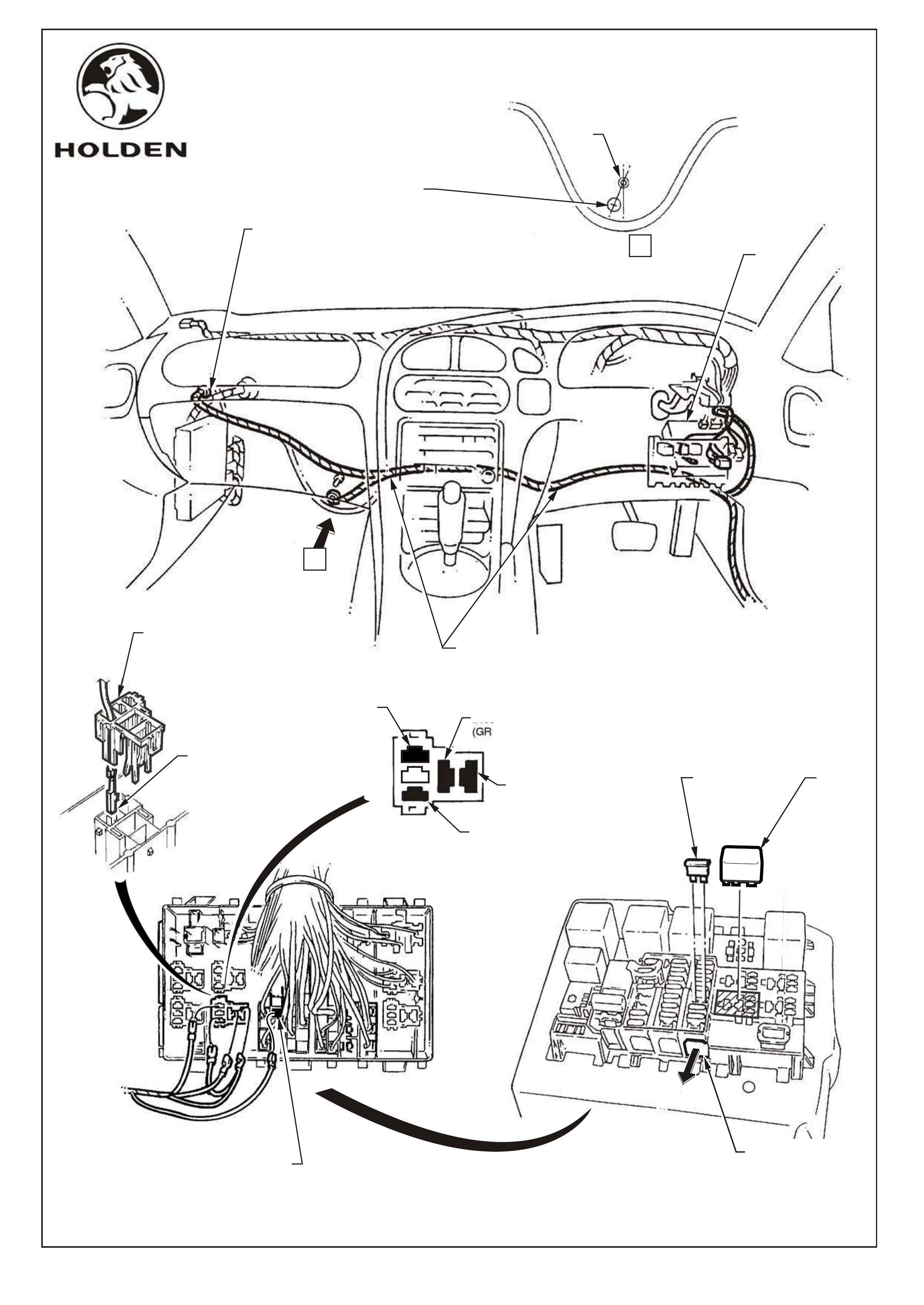
13. Sedans, built prior to Tag No. L553308:
Remove the grommet as shown in fig. 1 and ensure area around hole on the inside of the
cabin is clear of deadener material.
Sedans, built after and including Tag No. L553308, and all wagons:
Remove sound deadener material and drill 16mm dia. hole in prescribed area(LH lower lip of
cockpit module, refer fig. 1 View A). Ensure area around hole on the inside of the cabin is clear
of deadener material. Coat cut edge of hole and any bare metal with Zinc Chromate or
equivalent anti corrosion paint.
14. Remove white terminal retainer and fit fuse terminal (ORANGE/YELLOW wire) on patch harness as shown
in fig. 2. Replace white terminal retainer.
15. Raise yellow terminal retainer on the back of the relay block and fit alarm patch wiring as shown in fig 2.
Lower and secure yellow terminal retainer.
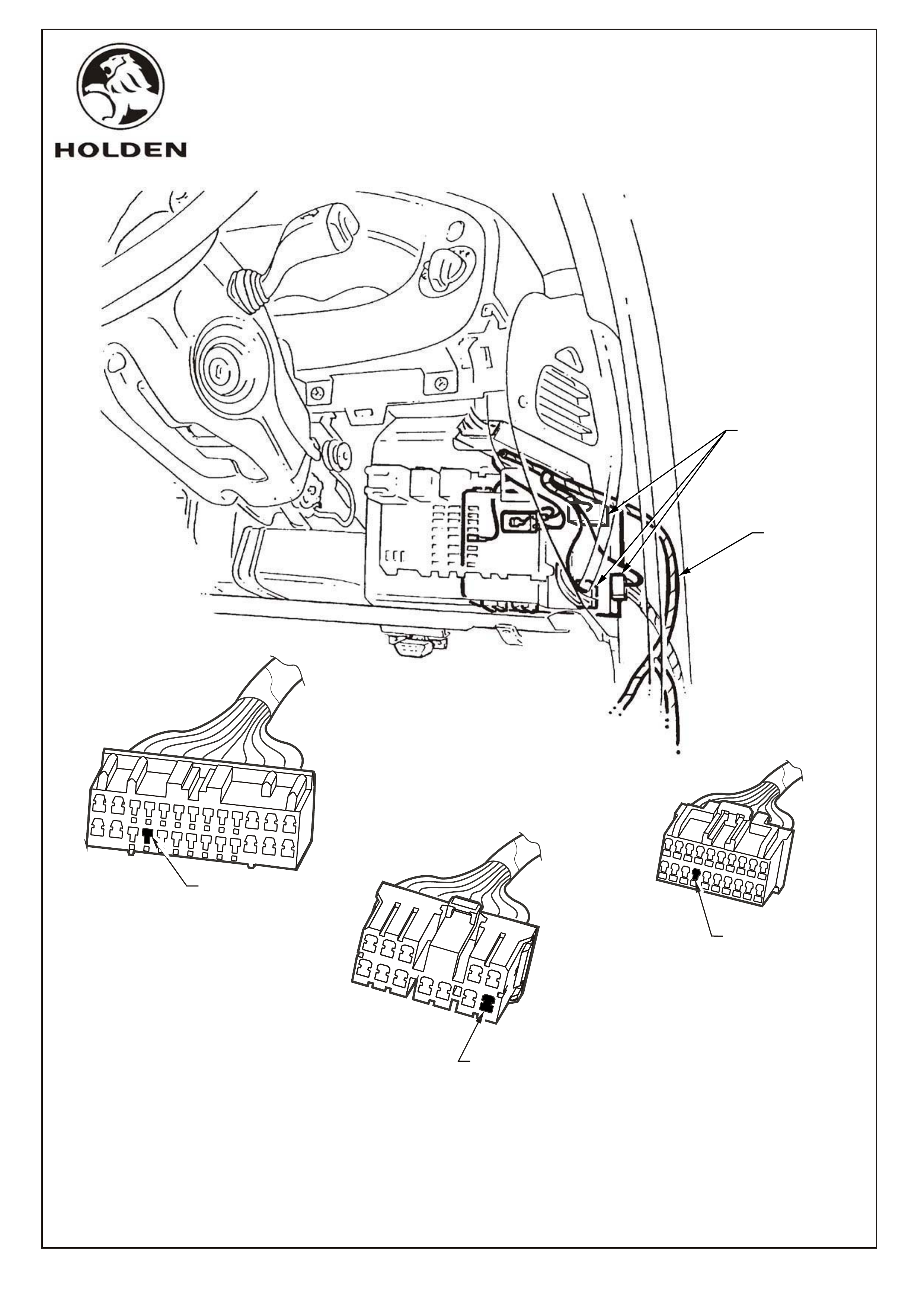
16. Locate the BCM terminals (Red/White wire, Black/White wire and Black/Yellow wire ) and routealong
existing wiring to BCM connectors.
17. Disconnect 26 pole BCM connector. Remove the locking wedges and insert the patch harness terminal,
Red/White wire, into cavity as shown in fig. 3.
NOTE : If existing wire appears in specified location of 26 pole BCM connector, remove terminal and tape
back. Insert Red/White wire from patch harness as per step 17.
18. Disconnect 20 pole BCM connector. Remove the locking wedges and insert the patch harness terminal,
Black/White wire, into cavity as shown in fig. 3.
19. Disconnect 12 pole BCM connector. Remove locking wedges and insert the patch harness terminal,
Yellow/Black wire, into cavity as shown in Fig.3
20. Replace the locking wedges.

HOLDEN SERVICE PARTS OPERATIONS
Reproduction in whole or part
prohibited without written approval
COPYRIGHT
FD914
28FE00
Division of HOLDEN Ltd ACN 006 893 232
Page 3 of 9
fd914c_3
21. Locate patch harness under carpet behind driver pedals, refer fig. 1. Feed the patch harness through to
LH side of vehicle. Ensure wiring is covered and not visible.
22. Feed patch harness into engine compartment either through existing hole(sedans prior to Tag No.
L553308)) or drilled hole(sedans after and including Tag No. L553308 and all wagons).
Locate grommet in hole ensuring it is fully pulled into position and is sealing against firewall.
Tape back excess wire in engine bay (sedan).
23. Seal grommet with a bead of silicon sealer.
24. Refit all trim items removed from RH side of vehicle.
25. Remove taped loops in patch harness for extra length (sedan only). Route the patch harness along RH sill
plate beside existing wiring (Body Harness) to the rear of the vehicle, refer fig. 4, securing in place with
adhesive tape.
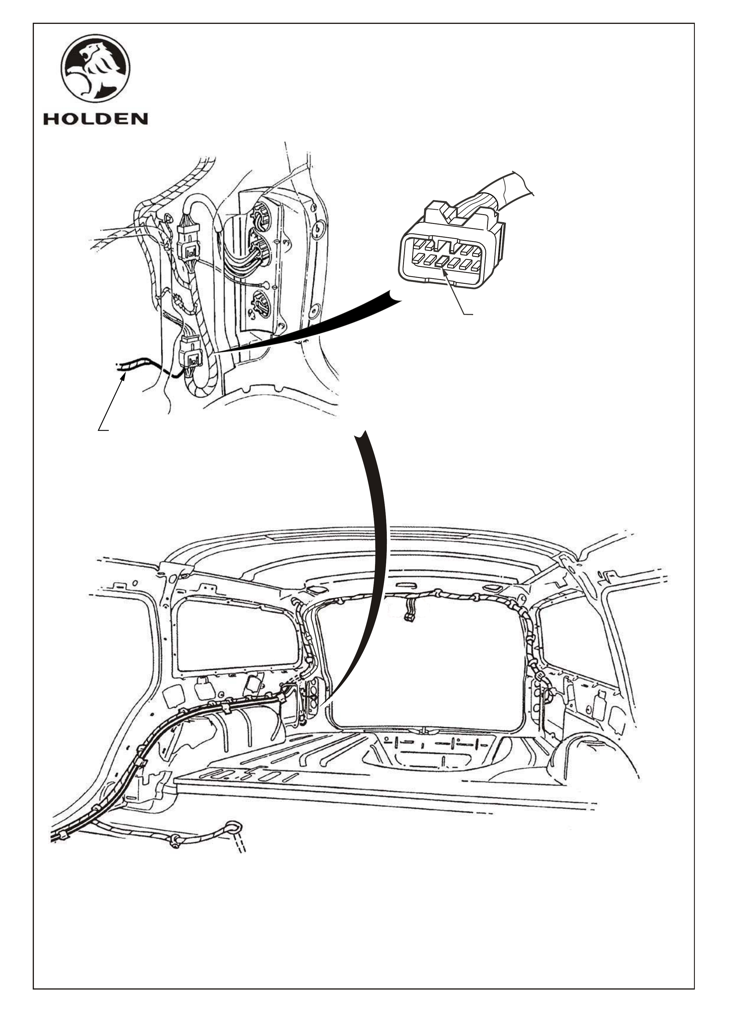
26. Sedan: Route patch harness along existing wiring harness, up decklid hinge into decklid and fit to
decklid switch, as shown in fig. 5. If a yellow/green wire from the existing wiring harness is
attached to the decklid switch, remove it and tape back prior to installing patch harness
terminal.
Wagon: Route patch harness to endgate harness connectors. Remove patch harness terminal cover
and insert patch harness terminal into connector, at location shown in fig. 6. If a yellow/green
wire from the existing wiring harness appears in the connector at the specified location, remove
it and tape back prior to inserting patsh harness terminal.
NOTE : If existing wire appears in specified location, remove terminal and tape back. Insert patch
harness as above.
27. Refit all trim items on the RH side of the vehicle and in the boot or luggage compartment.
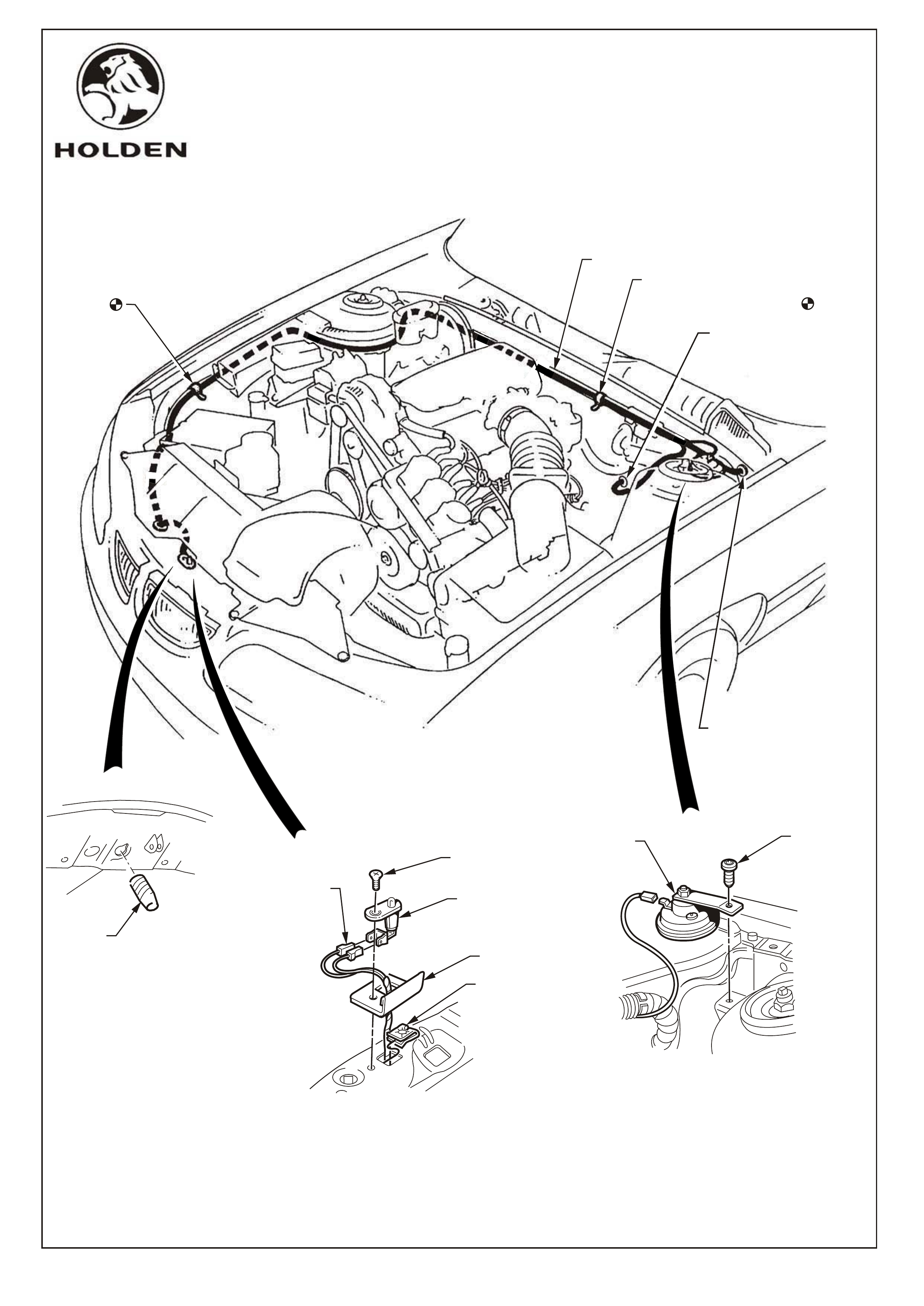
28. Route the patch harness along the firewall in the engine compartment, as shown in fig. 8, secure to the
existing wiring using integral tie straps.
29. Route wires around strut tower former. Remove screws securing relay box. Feed wires behind the
relay box and replace the screws.
30. Remove LH Front Grill cover. Feed alarm patch wires under fusible link housing and into radiator support.
Feed harness through existing bonnet switch hole, attach the bonnet switch to the patch harness and
secure the bonnet switch and shield with the screw provided.
31. Fit the rubber buffer to the bonnet and adjust so as to depress the switch when the bonnet is closed.
32. Mount the security horn to the bracket on the rear of the LH strut tower using Torx head screw.
Tighten screw 4.0 -6.0 Nm. Connect wiring to security horn.
33. Reconnect the battery.
34. Using TECH 2, enable BCM alarm option (refer to SERVICE MANUAL)
35. Fit relay and fuse into fuse panel.
36. Re-enable the air bag.
37. Test functionality, ie: alarm triggers off doors, bonnet, boot.
HOLDEN SERVICE PARTS OPERATIONS
Reproduction in whole or part
prohibited without written approval
COPYRIGHT
FD914
28FE00
Division of HOLDEN Ltd ACN 006 893 232
Page 4 of 9
fd914c_4
INSERT
ALARM
RELAY
INSERT ALARM
FUSE(15A)TO
POSITION F24
REMOVE EXISTING GROMMET,
INSERT PATCH HARNESS AND
GROMMET THROUGH HOLE
(SEDANS BUILT PRIOR TO
TAG NUMBER L553308)
BCM
INSERT TERMINAL
(ORANGE/YELLOW WIRE)
INTO FUSE POSITION F24
INSERT TERMINAL
(GREEN WIRE)
INSERT TERMINAL
(BLUE/RED WIRE)
INSERT TERMINAL
YELLOW/BLACK WIRE
REMOVE YELLOW RETAINER
TO ENABLE INSERTION OF
TERMINALS
FEED TERMINAL THRU
RETAINER INTO FUSE
PANEL CAVITY (4 PLACES) INSERT TERMINAL
(ORANGE/YELLOW WIRE)
DRILL 16,0mm DIA. HOLE AT "7 O'CLOCK"
POSITION TO EXISTING STUD, MID WAY
BETWEEN STUD AND BODY PANEL EDGE.
COAT EDGE OF CUT HOLE & ANY BARE
METAL WITH ZINC CHROMATE OR EQUIVALENT
ANTI CORROSION PAINT
EXISTING
STUD
VIEW A
A
BCM PATCH HARNESS
REMOVE WHITE
RETAINER
FIGURE 1
FIGURE 2
SEDANS BUILT AFTER & INCLUDING
TAG NUMBER L553308
& ALL WAGONS
HOLDEN SERVICE PARTS OPERATIONS
Reproduction in whole or part
prohibited without written approval
COPYRIGHT
FD914
28FE00
Division of HOLDEN Ltd ACN 006 893 232
Page 5 of 9
fd914c_5
FIGURE 3
12 POLE BCM CONNECTOR
INSERT TERMINAL (YELLOW/BLACK
WIRE FROM PATCH HARNESS)
20 POLE BCM CONNECTOR
INSERT TERMINAL
(BLACK/WHITE WIRE
FROM PATCH HARNESS)
26 POLE BCM CONNECTOR
INSERT TERMINAL
(RED/WHITE WIRE
FROM PATCH HARNESS)
BCM CONNECTORS
PATCH HARNESS

HOLDEN SERVICE PARTS OPERATIONS
Reproduction in whole or part
prohibited without written approval
COPYRIGHT
FD914
28FE00
Division of HOLDEN Ltd ACN 006 893 232
Page 6 of 9
fd914c_6
SECURE HARNESS WITH
ADHESIVE TAPE IN
5 PLACES
BODY HARNESS
BODY HARNESS
ACCESS HOLE
TO BOOT
ACCESS HOLE
TO BOOT
DECKLID
HINGE
ANTI-THEFT BCM
PATCH HARNESS
ANTI-THEFT BCM
PATCH HARNESS
FIGURE 4
FIGURE 5
PATCH HARNESS
CONNECTOR
DECKLID
SWITCH
SECURE
PATCH HARNESS
TO HINGE USING
INTEGRAL
TIE STRAPS
NOTE: IF TERMINAL EXISTS
AT THIS LOCATION,
REMOVE AND TAPE BACK
HOLDEN SERVICE PARTS OPERATIONS
Reproduction in whole or part
prohibited without written approval
COPYRIGHT
FD914
28FE00
Division of HOLDEN Ltd ACN 006 893 232
Page 7 of 9
fd914c_7
FIGURE 6
FIGURE 7
INSERT PATCH HARNESS
PATCH HARNESS
NOTE: IF TERMINAL EXISTS AT THIS
LOCATION, REMOVE AND TAPE BACK
HOLDEN SERVICE PARTS OPERATIONS
Reproduction in whole or part
prohibited without written approval
COPYRIGHT
FD914
28FE00
Division of HOLDEN Ltd ACN 006 893 232
Page 8 of 9
fd914c-8
V6 SHOWN - V8 SIMILAR
SECURE PATCH HARNESS TO
EXISTING MAIN WIRING HARNESS
WITH INTEGRAL TIE STRAPS
SEDANS BUILT AFTER &
INCLUDING TAG NUMBER
L553308 & ALL WAGONS
SEDANS BUILT PRIOR TO
TAG NUMBER L553308
MAIN WIRING HARNESS
FIGURE 8
RUBBER
BUFFER
SCREW
BONNET
SWITCH
BONNET
SWITCH
CONNECTOR
SHIELD
TORX HEAD
SCREW
4,0 - 6,0Nm
SECURITY
HORN
"J" NUT

PART NUMBER DESCRIPTION QUANTITY
HOLDEN SERVICE PARTS OPERATIONS
Reproduction in whole or part
prohibited without written approval
COPYRIGHT
FD914
28FE00
Division of HOLDEN Ltd ACN 006 893 232
Page 9 of 9
fd914c_9
FITTING INSTRUCTIONS
VT SERIES 2 ANTI-THEFT ALARM PACKAGE
Part Number 92142888
Parts List
92142887 WIRING HARNESS 1
92057212 SWITCH 1
92036585 SHIELD 1
11038825 SCREW 1
3466306 BUFFER 1
92056649 SECURITY HORN 1
92138274 TORX HEAD SCREW 1
92047112 RELAY 1
12092078 15AMP FUSE 1
92138008 J-NUT 1
FD914 FITTING INSTRUCTION BOOKLET 1