1. Disconnect the battery negative lead.
NOTE: To reinstate the audio system the security
code will be required.
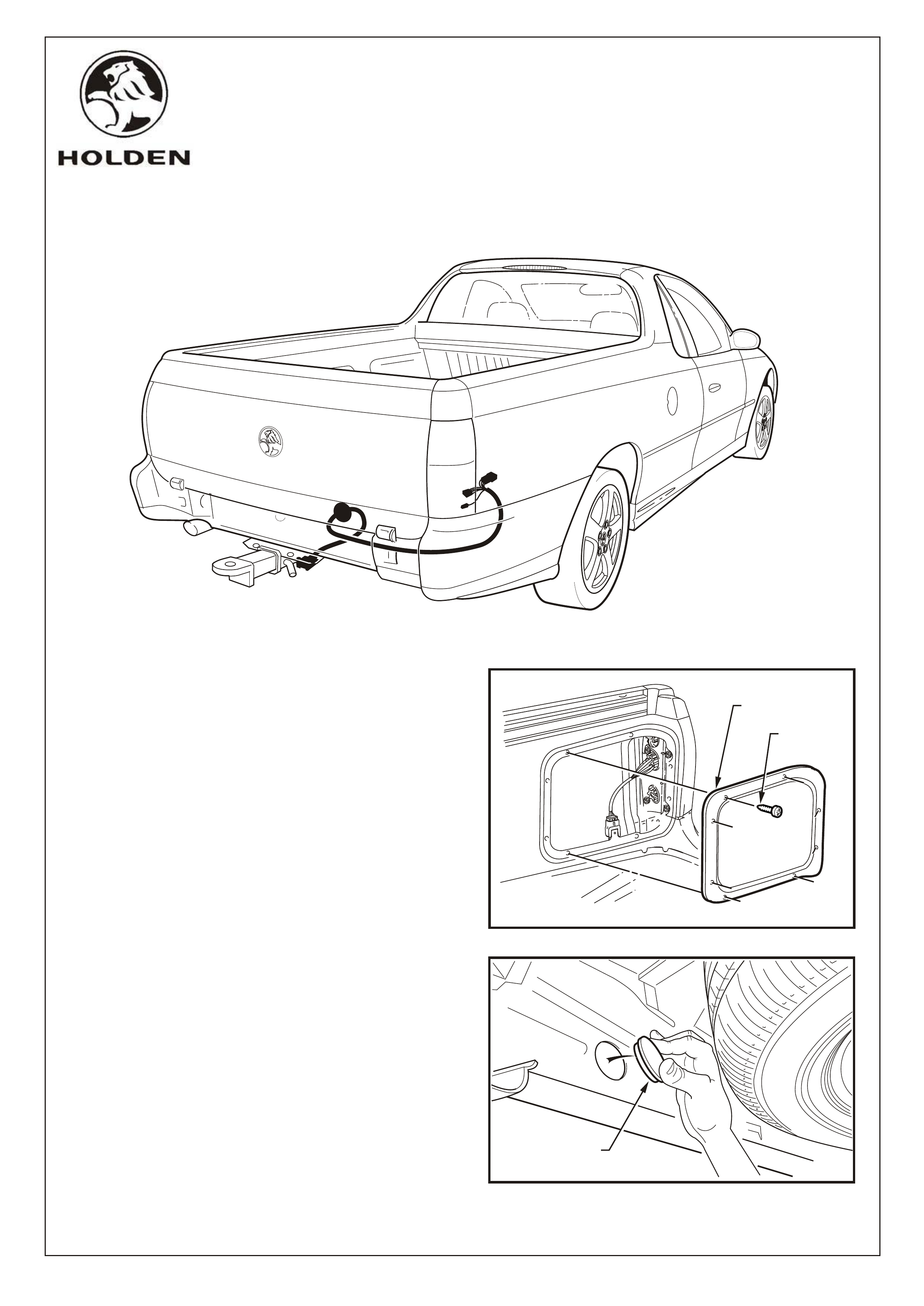
2. Access the tail lamp harness connectors by removing
the screws (8 places) attaching the RH cover panel to
the inner side panel. Refer Figure 1
NOTE: Sealer is applied around the cover panel's
perimeter.
3. Remove the grommet from the rear end inner panel
and discard. Refer Figure 2
FITTING INSTRUCTIONS FOR
VU UTILITY TRAILER WIRING HARNESS
Part Number 92142517
COPYRIGHT
Page 1 of 3
FD961-01
Reproduction in whole or part
prohibited without written approval
HOLDEN SERVICE PARTS OPERATIONS
Division of HOLDEN Ltd ACN 006 893 232
SCREW
8 PLACES
COVER PANEL
GROMMET
FITTING INSTRUCTIONS
..
..
......
..
..
..
....
..
..
..
..
..
..
..
..
..
..
..
..
..
..
....
....
....
..
..
..
..
..
....
..
..
..
..
..
..
..
..
..
..
FIGURE 1
FIGURE 2
FD961
15DE00
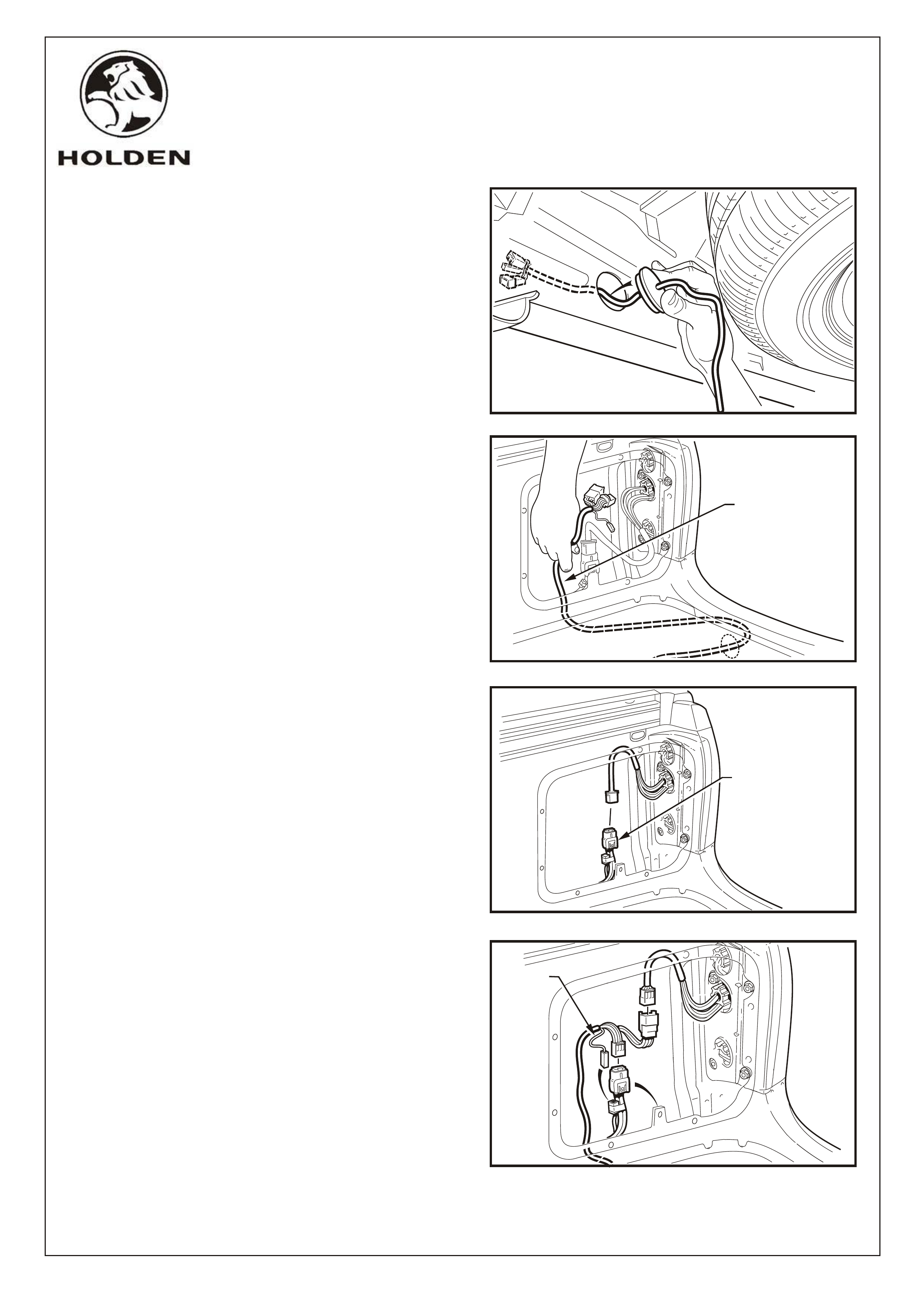
4. Insert the trailer patch harness through the hole in
rear end inner panel and feed through to the RH side.
Install Grommet. Refer Figure 3.
TIP: Tape the connectors together to ease
installation.
5. Reach in through the quarter panel opening and pull
the harness through to access connectors. Refer
Figure 4.
6. Remove the tail lamp harness connector from the
mounting tang and disconnect. Refer Figure 5.
7. Connect the trailer patch harness connectors
between the body harness and tail lamp connectors.
Refer Figure 6.
8. Connect the yellow lead (LH turn connector) on the
trailer patch harness to the taped-back connector on
the body harness. Refer Figure 6
9. Re-install the body harness connector back onto the
mounting tang. Refer Figure 6
10. Re-connect the battery negative lead and check the
COPYRIGHT
Page 2 of 3
Reproduction in whole or part
prohibited without written approval
HOLDEN SERVICE PARTS OPERATIONS
Division of HOLDEN Ltd ACN 006 893 232
FD961-02
..
..
......
..
..
..
....
..
..
..
..
..
..
..
..
..
..
..
..
..
..
....
....
....
..
..
..
..
..
....
..
..
..
..
..
..
..
..
..
..
PULL HARNESS
THROUGH
REMOVE CONNECTOR
FROM TANG
YELLOW
LEAD
FIGURE 3
FIGURE 4
FIGURE 5
FIGURE 6
FD961
15DE00
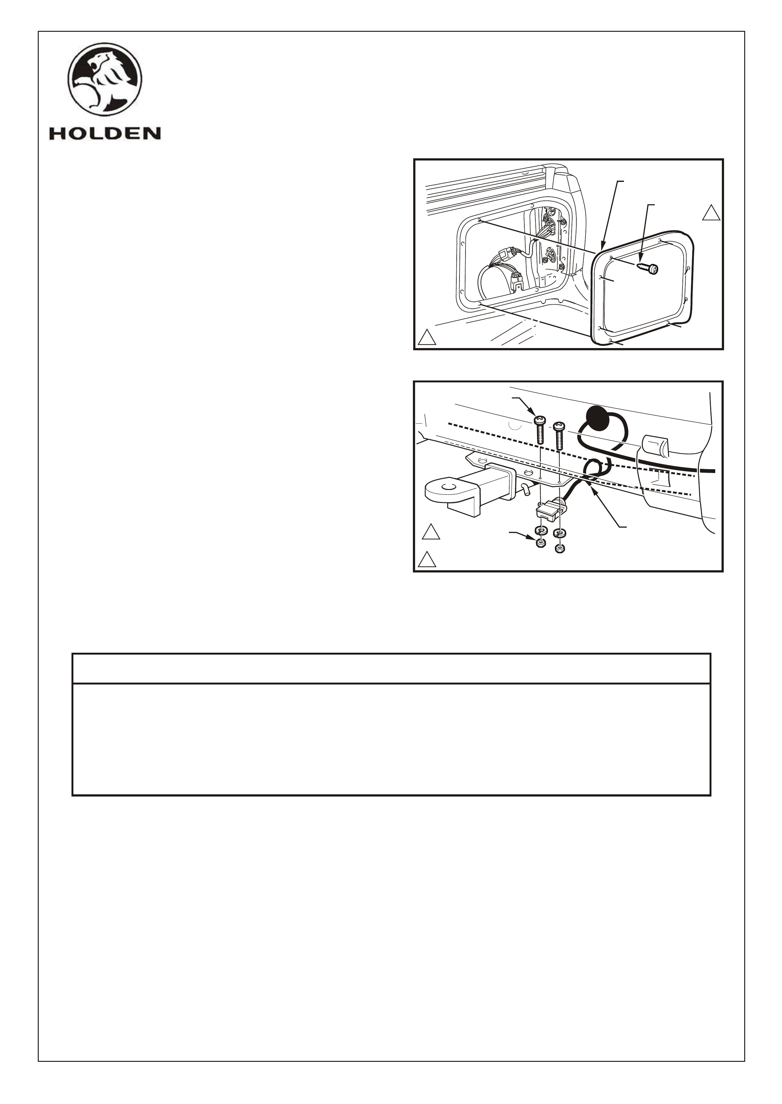
11. Install the cover panel onto the RH inner side panel
with the existing screws, 8 places. Tighten to 1.0 ~
3.0 Nm. Refer Figure 7.
NOTE: Replace the sealer if required.
13. Route the trailer patch harness under the tow bar and
using the screws, washers and nuts supplied, mount
the 7 pin flat connector to the tow bar. Tighten to 2.0 ~
3.0 Nm. Refer Figure 8.
14. Feed any excess harness into the rear end panel
cavity. Tie strap harness to tow bar tube. Refer
Figure 8.
15. Reinstate the audio system by entering the security
code, refer owner's manual.
NUT, 2 PLACES
SPRING WASHER
2 PLACES
TIE STRAP
SCREW, 2 PLACES
COPYRIGHT
Page 3 of 3
Reproduction in whole or part
prohibited without written approval
HOLDEN SERVICE PARTS OPERATIONS
Division of HOLDEN Ltd ACN 006 893 232
FD961
15DE00
FD961-03
SCREW,
8 PLACES
COVER PANEL
1
1
1
1
1.0 ~ 3.0 Nm
2.0 ~ 3.0 Nm
PART NO. DESCRIPTION QUANTITY
92142517 TRAILER HARNESS - FLAT 7 PIN 1
SCREW 2
WASHER - SPRING 2
NUT 2
CABLE TIE 1
FD961 FITTING INSTRUCTION BOOKLET 1
PARTS LIST
FIGURE 7
FIGURE 8