Reproduction in whole or part
prohibited without written approval
COPYRIGHT
FD980
26OCT04
HOLDEN LTD
Division of HOLDEN Ltd ACN 006 893 232
FITTING INSTRUCTIONS FOR
VX ROO BAR PACKAGE
Part No. - 92143511
(Silver Clear Finish)
or
Part No. - 92143512
(Textured Black Finish)
FITTING INSTRUCTIONS
1. Disconnect battery negative terminal.
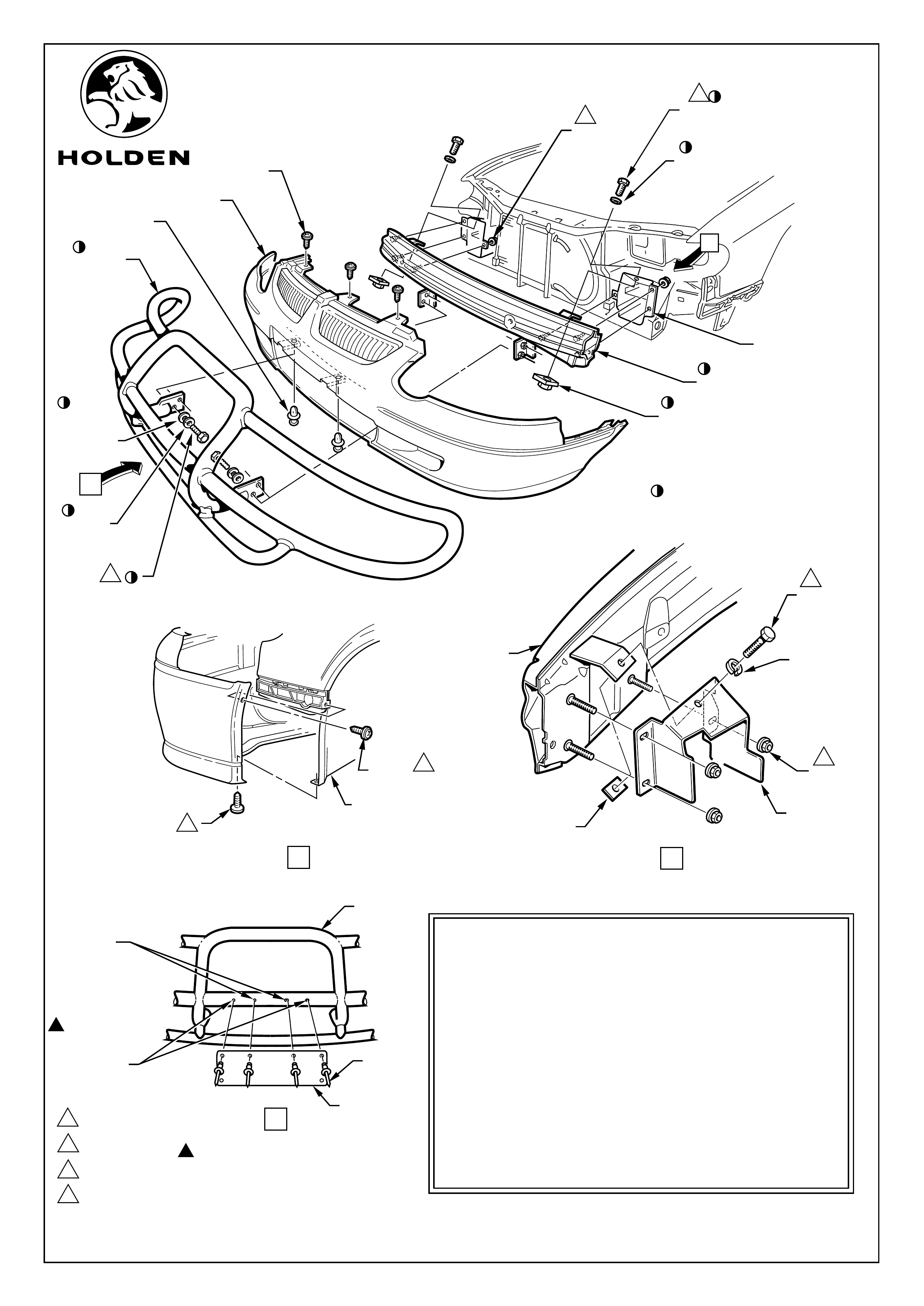
2. Remove front bumper facia, refer Holden Service Manual and Figure 1, (retain all fasteners).
3. Remove horn/s (one or two dependant on vehicle model) from bumper beam, refer Service Manual.
4. Remove fog lamps (if fitted), refer Service Manual, then remove bumper beam from vehicle. Refer Service
Manual and Figure 1.
5. Remove LH and RH headlamp assemblies, refer Service Manual.
6. Install new bumper/roo bar support beam, attach M8 nuts (6 places) and hand tighten. Reattach horn/s and
fog lamps (if fitted) to new bumper beam, refer Service Manual.
7. Install M10 bolt, spring washer and weld nut plate to bumper beam bracket and welded tab on bumper
beam. Refer Figure 1,View B.
8. Tighten M8 nuts 20 - 30Nm (6 places).
9. Tighten M10 bolts to 45Nm (2 places).
10. Reinstall LH and RH headlamp assemblies, refer Service Manual.
11. Reinstall front bumper facia, refer Service Manual and Figure 1.
12. Install roo bar to brackets on bumper/roo bar support beam, using M12 bolts, spring washers and flat
washers supplied in package. Refer Figure 1. Tighten M12 nuts to 75Nm, (4 places).
13. Remove number plate from bumper facia. Check alignment of upper outermost mounting holes in number
plate with dimples in roo bar. Refer Figure 1, View C.
14. Providing number plate holes match dimple positions, drill 4.7mm dia. holes at dimples and attach number
plate using rivets supplied (2 places). Use number plate as a template to drill two more 4.7mm dia. holes for
number plate mounting and fix using rivets supplied (2 places). Refer Figure 1, View C.
15. Reconnect the battery negative terminal.
16. Check alignment of headlamps and fog lamps (if fitted) and adjust if necessary, refer Service Manual.
17. On completion of installation, place fitting instructions in glove box.
For model applications, refer dealer
Page 1 of 2
Reproduction in whole or part
prohibited without written approval
COPYRIGHT
FD980
26OCT04
HOLDEN LTD
Division of HOLDEN Ltd ACN 006 893 232
Page 2 of 2
Figure 1
VIEW A
VIEW C
FRONT FENDER
INNER LINER
SCREW
(2 PLACES)
SCREW
(2 PLACES)
USE NUMBER
PLATE AS A
TEMPLATE TO
DRILL 4.7
DIA. HOLES
DRILL 4.7 DIA.
HOLES
AT DIMPLE
LOCATIONS
ROO
BAR
NUMBER
PLATE
PRIOR TO DRILLING AT DIMPLE
LOCATIONS , CHECK NUMBER
PLATE MOUNT HOLES MATCH
DIMPLE LOCATIONS. IF NOT,
DRILL TO SUIT PLATE.
RIVET
(4 PLACES)
BUMPER/ROO BAR
SUPPORT BEAM
FRONT BUMPER FACIA
ROO BAR
SCREW
(3 PLACES)
SCRIVET
(2 PLACES)
M8 NUT
(6 PLACES)
VX ROO BAR PACKAGE -
92143511 (Silver Clear Finish)
or 92143512 (Textured Black Finish)
Parts List
PART No. DESCRIPTION QTY
ROO BAR 1
BUMPER/ROO BAR SUPPORT BEAM 1
BOLT, M12 4
SPRING WASHER, 12mm DIA. 4
FLAT WASHER, 12mm DIA. 4
BOLT, M10 2
SPRING WASHER, 10mm DIA. 2
WELD NUT PLATE, M10 2
RIVET, 4.5 DIA. 4
FD980 FITTING INSTRUCTIONS 1
SPRING
WASHER
M8 NUT
(3 PLACES)
M10 WELD
NUT PLATE
BUMPER/ROO BAR
SUPPORT BEAM
M10 BOLT
(2 PLACES)
M10 WELD NUT PLATE
(2 PLACES)
SPRING WASHER
(2 PLACES)
2
M10 BOLT
2
2
1
1
2
375Nm
45Nm
20 - 30Nm
BUMPER BEAM
BRACKET
BUMPER BEAM
BRACKET
LH SHOWN
RH OPPOSITE
VIEW B
PART OF ROO BAR PACKAGE
C
4
4
4
1 - 3Nm
FLAT
WASHER
(4 PLACES)
M12 BOLT
(4 PLACES)
3
B
SPRING
WASHER
(4 PLACES)