FITTING INSTRUCTIONS FOR
VU UTILITY SPORTS BAR KIT
Part Number 92142889
COPYRIGHT
Page 1 of 4
HOLDEN SERVICE PARTS OPERATIONS
Reproduction in whole or part
prohibited without written approval
Division of HOLDEN Ltd ACN 006 893 232
FD996-1
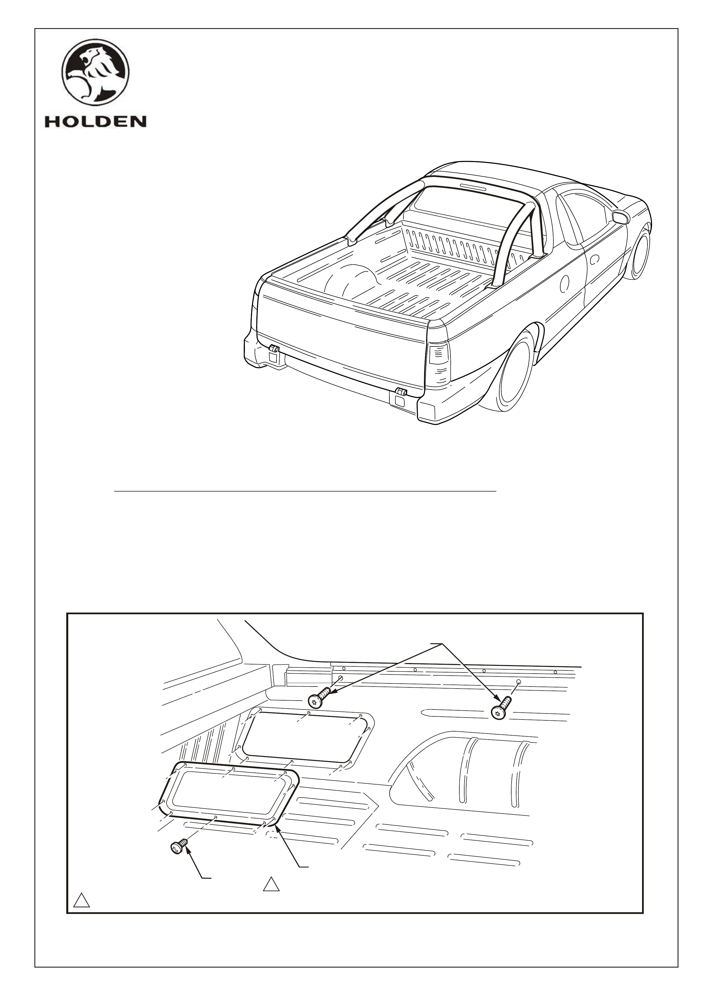
SCREW,
10 PLACES
SIDE COVER PANELl
REMOVE & DISCARD
CAP SCREW,
2 PLACES
1
11.0 ~ 3.0 Nm
FD996
31JL02
FITTING INSTRUCTIONS
1. Disconnect the battery negative lead.
NOTE: To reinstate the audio system the security code will be required.
2. IMPORTANT: Remove all plastic protective wrapping from the sports bar
3. Remove the ten screws attaching the RH front load compartment side cover to the inner side
panel. Remove the cover.
NOTE: Care must be taken not to distort side cover panel on removal, due to sealer applied
around the perimeter panel. If sealer is not reusable, remove and re-apply with a similar type
sealer.
4. From each side of the vehicle, remove the centre and front side rail cap screws.

SPORTS BAR
ASSEMBLY
COPYRIGHT
Page 2 of 4
FD996-2
HOLDEN SERVICE PARTS OPERATIONS
Reproduction in whole or part
prohibited without written approval
Division of HOLDEN Ltd ACN 006 893 232
5. Drill a 10.0 mm hole through the side rail
cap and body panel. Refer Figure 2.
NOTE: Care must be taken not to drill
through to the body side outer panel.
6. Vacuum up any swarf and apply primer to
any bare metal.
7. With the aid of an assistant, position the
sports bar above mounting holes
8. Remove grommet from high mount stop
harness lamp and retain. Tape harness
connector ends together and then feed the
harness through the drilled holes.Locate
sports bar to align with hole locations and
install the cap screws & washers- 4 places.
Tighten to the specified torque.
NOTE: Ensure harness is pulled thru the
holes so that no pinching occurs
FIGURE 2
FIGURE 3
FIGURE 2
FIGURE 2
EXISTING
NUTSERT
HOLE
DRILL 10mm
HOLES
FIGURE 3
11.0 ~ 3.0Nm
1
SCREW
(4 PLACES)
WASHER
(4 PLACES)
HIGH MOUNT
STOP LAMP HARNESS
17 mm
55 mm
FD996
31JL02
COPYRIGHT
Page 3 of 4
FD996-3
HOLDEN SERVICE PARTS OPERATIONS
Reproduction in whole or part
prohibited without written approval
Division of HOLDEN Ltd ACN 006 893 232
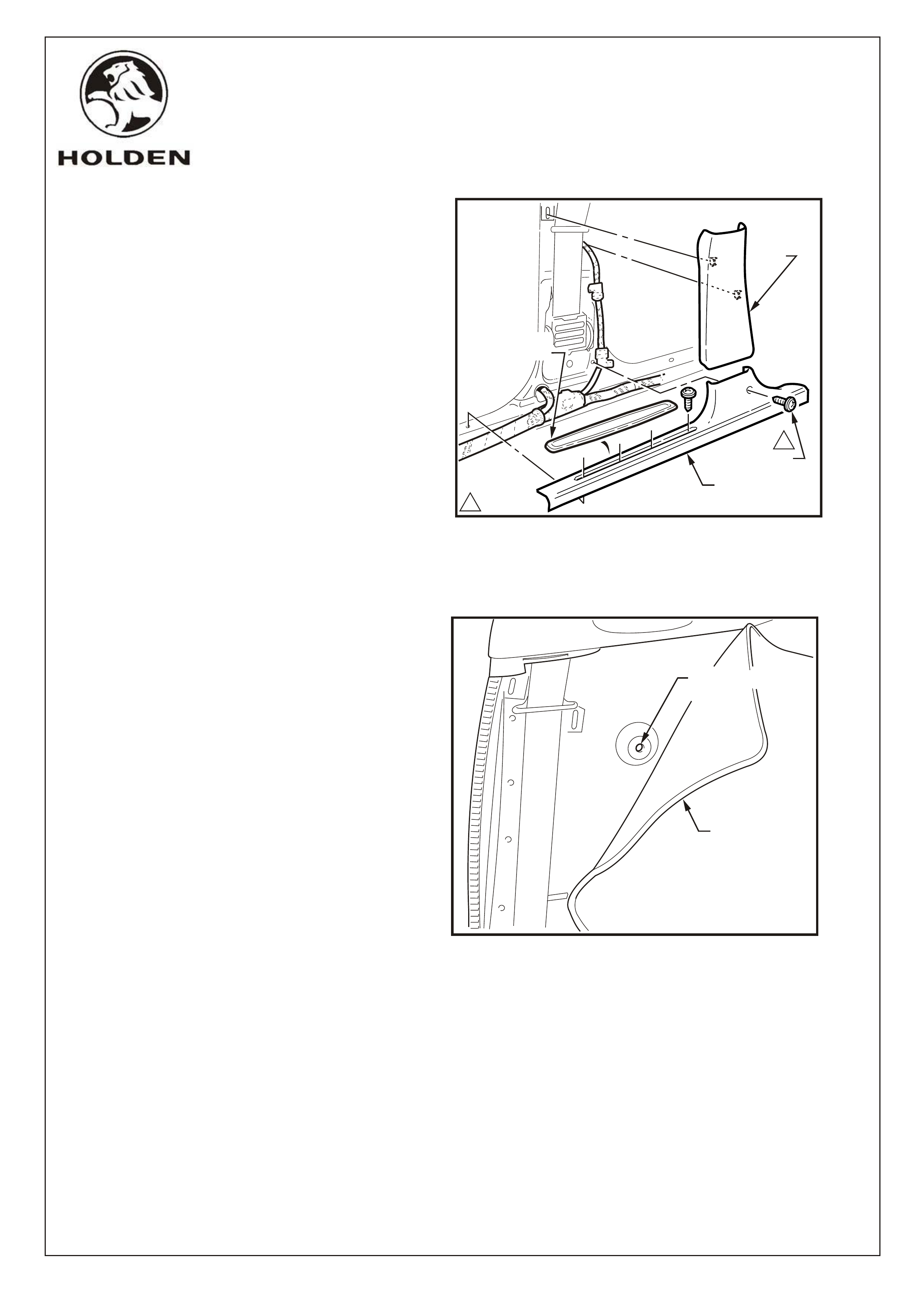
10. Roll back side trim and drill 8.0 mm dia.
hole in the centre of the boss on the inner
pane. Vacuum up any swarf and aplpy
primer to any bare metal. Refer Figure 5
NOTE: Care must be taken rolling back the
trim to ensure the baking is not damaged.
FIGURE 5
DRILL 8.0mm
DIA. HOLE
FIGURE 4FIGURE 4
1
11.0 ~ 3.0Nm
LOWER "B"
PILLER
TRIM
SCREW
(5 PLACES)
COVER ASM
INNER ROCKER
ROLL BACK
TRIM COVER
INSERT COVER
ROCKER PANEL
9. From inside the cabin, remove the rocker
panel cover and B-pillar lower trim. Refer
Figure 4.
FD996
31JL02
COPYRIGHT
Page 4 of 4
FD996-4
HOLDEN SERVICE PARTS OPERATIONS
Reproduction in whole or part
prohibited without written approval
Division of HOLDEN Ltd ACN 006 893 232
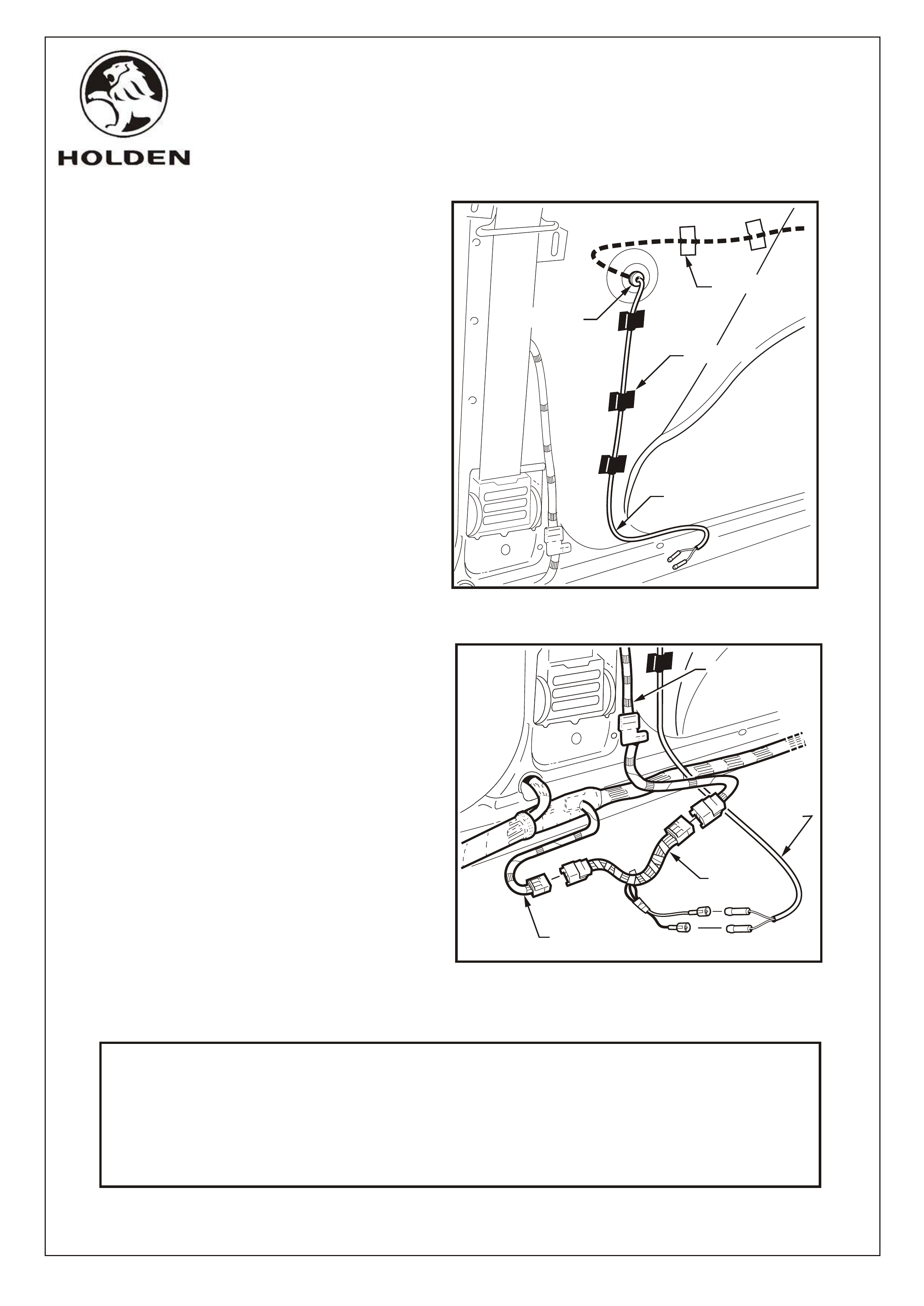
11. Feed the high mount stop lamp harness
along the panel cavity and through hole in
inner panel Instal grommet to harness and
fit into hole. Spot tape as shown.
12. Locate the roof lamps harness connector at
the base of the B-pillar and disconnect.
Refer Figure 7.
13. Install the patch harness supplied in the kit
between the two roof lamps harness
connectors. Refer Figure 7.
14. Install the sports bar high mount stop lamp
harness connector onto the patch harness.
Refer Figure 7.
15. Reconnect the battery negative lead and
test the sports bar high mount stop lamp
for correct operation.
16. Reinstall the interior trim.
17. Reinstall the side cover using the existing
screws. Tighten to the specified torque.
NOTE: Replace the sealer if required.
Refer Figure 1, page 1.
18. Reinstate the audio system by entering the
security code, refer owner's manual.
19. Place the fitting instructions in the
glovebox.
PART NO. DESCRIPTION QTY
SPORTS BAR ASSEMBLY 1
MOUNTING SCREWS 4
PATCH HARNESS 1
FD996 SPORTS BAR FITTING INSTRUCTIONS 1
FD796 WARRANTY CARD 1
PARTS LIST
FIGURE 7
HIGH MOUNT
STOP LAMP
HARNESS
ROOF LAMP
HARNESS
PATCH
HARNESS
BODY
HARNESS
FIGURE 6
HIGH MOUNT
STOP LAMP
HARNESS
GROMMET
SPOT TAPE
SPOT TAPE
FD996
31JL02