INSTALLATION INSTRUCTIONS
HOLDEN SERVICE PARTS OPERATIONS
Division of Holden Ltd
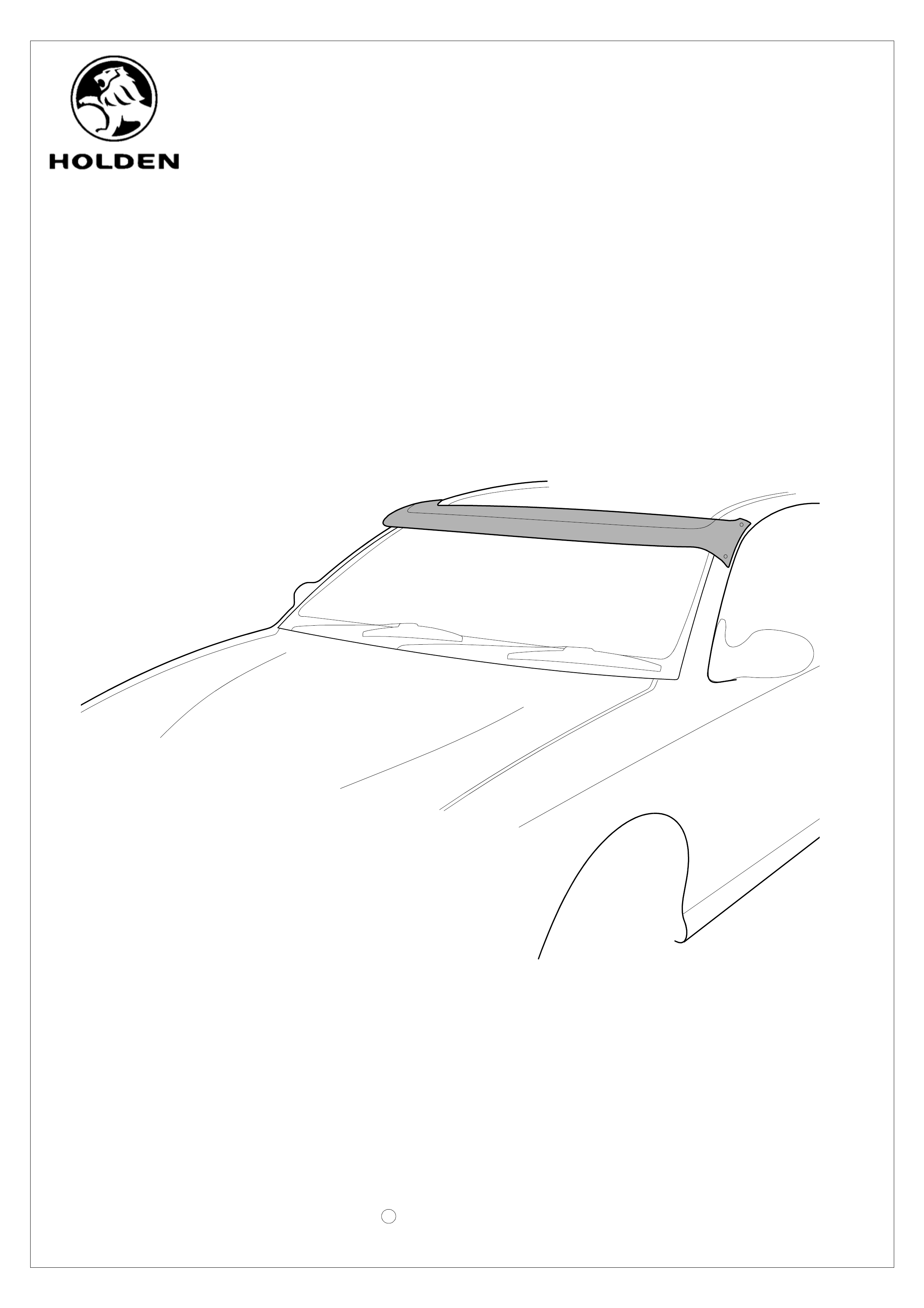
SUN SHADE
SV 4
Patent Pending
Design Registration Pending
Page 1 of 4
VT - VY COMMODORE
COPYRIGHT
Reproduction in whole or part
prohibited without written approval
c
Part No. 92144156
HOLDEN SERVICE PARTS OPERATIONS
Division of Holden Ltd
SV 4
SUN VISOR
JACK NUT
FRICTION WRENCH
1
4
4
RUBBER WASHER
FITTING INSTRUCTION BOOKLET
DESCRIPTION QTYPART No.
COPYRIGHT
Reproduction in whole or part
prohibited without written approval
c
Page 2 of 4
READ THROUGH INSTRUCTIONS CAREFULLY BEFORE PROCEEDING
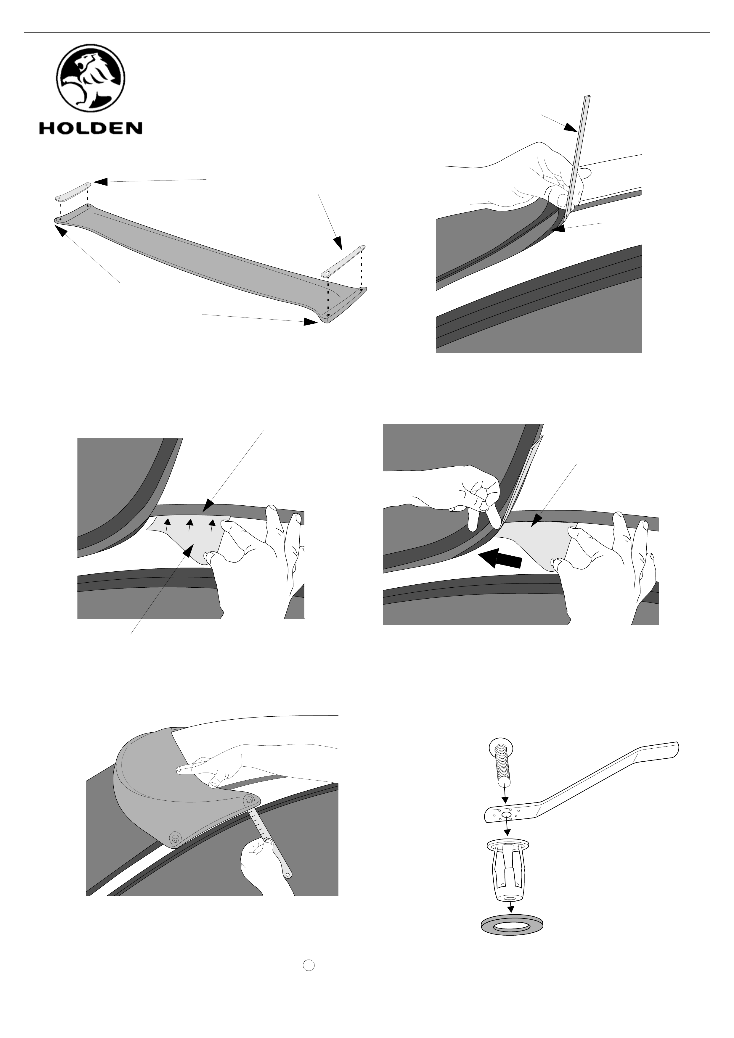
Ensure that the hardware kit has all of its necessary components. Clean Sun Visor feet with one of the alcohol wipes provided and
remove any residue with a dry clean cloth. Attach the adhesive foam pads to the Sun Visor feet ensuring the holes and cut-out
on the foam pads align with the bolt holes and the drainage holes on the visor ( figure 1.).
Clean areas where the visor comes into contact with the vehicle using warm soapy water and dry thoroughly. Carefully lift outer lip
of the windscreen seal and place a small metal ruler or equivalen t as described in (figure 2. ). NOTE: Do not completely lift
out entire seal.
Cut out the template attached (page 4), using the dashed line to cut out the locating slot. Using the template, alig n edge A to the
vehicle as shown (figure 3.).
Slide the template forward until it comes into flush contact with the ruler as in (fig ure 4. ). Ensuring the template is flat against the
vehicle, mark the position of the slot on the vehicle. NOTE: The slot denotes fore and aft position of the rear bolt locations
ONLY.
Use the same template to locate the position of the rear bolt on the opposite side of the vehicle.
Trial fit the visor to the vehicle. Line the rear holes with the lines drawn on either side, and using a ruler, ensure that it is positioned
centrally across the vehicle. Mark all holes once positione d correctly. (figure 5.)
Centre punch the hole positi ons lightly. Pilot drill the positi on of the bolts using 3mm drill bit and then finish drilling wi th an 11mm
drill bit. De-burr holes and apply rust inhibitor to all exposed metal (4 locations).
Assemble the supplied screw, friction wrench, rubber washer and jack nut as shown in (figure 6.). NOTE: Do not tighten the screw
at this point.
Insert the body of the jack nut into one of the drilled holes. Firmly holding the flange of the jack nut against the skin of the
vehicle pressing down with the friction wren ch and using the supplied allen key, tighten the screw until the jack nut collaps-
es and secures positively to the vehicle. Remove screw and friction wrench le aving behind the jack nut. Repeat steps 9 & 10
for the remaining 3 holes. NOTE: Ensure a new friction wrench is used for each hole.
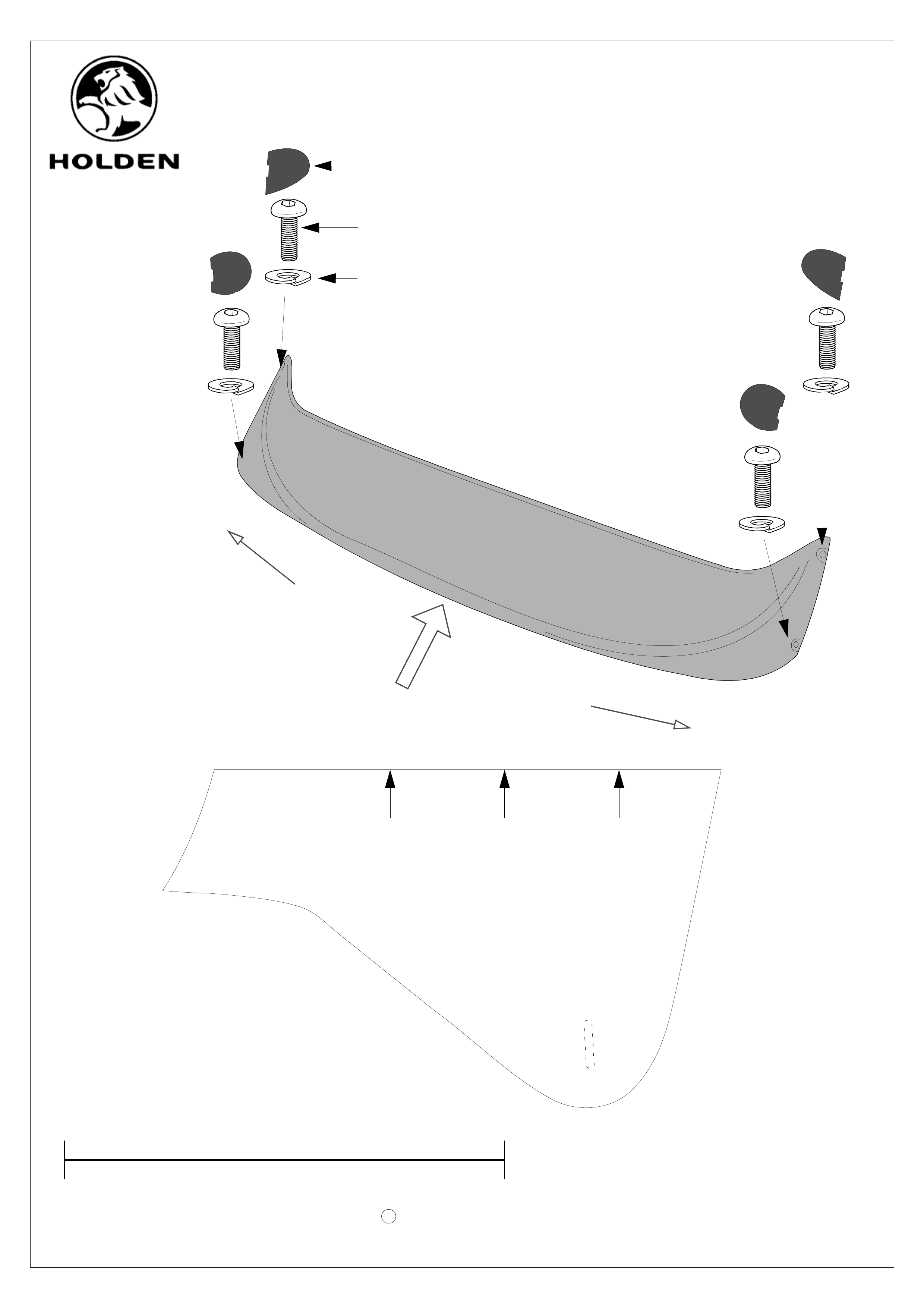
Reposition the visor and install the screws and split washers, securing firmly. Tighten to a maximum of 10Nm. (figure 7.)
Clean end cap recesses with the remaining alcohol wipe provided and remove any residue with a dry clean cloth.
Remove lining from double side d adhesive tape and insert en d caps into their respective locati ons. NOTE: All endcaps must fit
into their respective recesses. (figure 7.)
PLACE INSTRUCTIONS IN GLOVE BOX WHEN INSTALLATION IS COMPLETE.
FITTING INSTRUCTIONS
1.
2.
3.
4.
PLASTIC END CAP
5.
6.
7.
ALLEN KEY
4
1
4
1
PARTS LIST
8.
10.
11.
12.
9.
13.
14.
RUST INHIBITOR 1
ALCOHOL WIPE 2
SPLIT WASHER 4
ALCOHOL WIPE 2
SCREW 4
FOOT PADS (LHS & RHS) 2
HOLDEN SERVICE PARTS OPERATIONS
Division of Holden Ltd
SV 4
Page 3 of 4
Figure 1.
Figure 6.
COPYRIGHT
Reproduction in whole or part
prohibited without written approval
c
Single sided
Clean Sun Visor feet
with alcohol wipe
adhesive foam pads
Figure 2.
Figure 3. Figure 4.
Template
Align Edge A
Metal Ruler
Windscreen Seal
Sliding template flush
against ruler
Figure 5.
HOLDEN SERVICE PARTS OPERATIONS
Division of Holden Ltd
Page 4 of 4
COPYRIGHT
Reproduction in whole or part
prohibited without written approval
c
EDGE A
100mm when printed
SV 4
THIS FACE UP FOR LHS
THIS FACE DOWN FOR RHS
Figure 7.
Split Washer
Screw
Plastic End Cap
L
L
R
R
LHS
RHS
LOOKING
FROM
FRONT OF
VEHICLE